EP2408381B1 - Système de stabilisation de vertèbres dans une chirurgie rachidienne par le biais d'un canal d'accès latéral - Google Patents
Système de stabilisation de vertèbres dans une chirurgie rachidienne par le biais d'un canal d'accès latéral Download PDFInfo
- Publication number
- EP2408381B1 EP2408381B1 EP10710717.9A EP10710717A EP2408381B1 EP 2408381 B1 EP2408381 B1 EP 2408381B1 EP 10710717 A EP10710717 A EP 10710717A EP 2408381 B1 EP2408381 B1 EP 2408381B1
- Authority
- EP
- European Patent Office
- Prior art keywords
- plate
- alignment
- spacer
- superior
- recited
- Prior art date
- Legal status (The legal status is an assumption and is not a legal conclusion. Google has not performed a legal analysis and makes no representation as to the accuracy of the status listed.)
- Active
Links
- 0 **[C@]1[C@@](CCC=I)C(C2)C2CC1* Chemical compound **[C@]1[C@@](CCC=I)C(C2)C2CC1* 0.000 description 1
Images


Classifications
-
- A—HUMAN NECESSITIES
- A61—MEDICAL OR VETERINARY SCIENCE; HYGIENE
- A61B—DIAGNOSIS; SURGERY; IDENTIFICATION
- A61B17/00—Surgical instruments, devices or methods, e.g. tourniquets
- A61B17/56—Surgical instruments or methods for treatment of bones or joints; Devices specially adapted therefor
- A61B17/58—Surgical instruments or methods for treatment of bones or joints; Devices specially adapted therefor for osteosynthesis, e.g. bone plates, screws, setting implements or the like
- A61B17/68—Internal fixation devices, including fasteners and spinal fixators, even if a part thereof projects from the skin
- A61B17/70—Spinal positioners or stabilisers ; Bone stabilisers comprising fluid filler in an implant
- A61B17/7059—Cortical plates
-
- A—HUMAN NECESSITIES
- A61—MEDICAL OR VETERINARY SCIENCE; HYGIENE
- A61B—DIAGNOSIS; SURGERY; IDENTIFICATION
- A61B17/00—Surgical instruments, devices or methods, e.g. tourniquets
- A61B17/16—Bone cutting, breaking or removal means other than saws, e.g. Osteoclasts; Drills or chisels for bones; Trepans
- A61B17/17—Guides or aligning means for drills, mills, pins or wires
- A61B17/1728—Guides or aligning means for drills, mills, pins or wires for holes for bone plates or plate screws
-
- A—HUMAN NECESSITIES
- A61—MEDICAL OR VETERINARY SCIENCE; HYGIENE
- A61B—DIAGNOSIS; SURGERY; IDENTIFICATION
- A61B17/00—Surgical instruments, devices or methods, e.g. tourniquets
- A61B17/16—Bone cutting, breaking or removal means other than saws, e.g. Osteoclasts; Drills or chisels for bones; Trepans
- A61B17/17—Guides or aligning means for drills, mills, pins or wires
- A61B17/1739—Guides or aligning means for drills, mills, pins or wires specially adapted for particular parts of the body
- A61B17/1757—Guides or aligning means for drills, mills, pins or wires specially adapted for particular parts of the body for the spine
-
- A—HUMAN NECESSITIES
- A61—MEDICAL OR VETERINARY SCIENCE; HYGIENE
- A61B—DIAGNOSIS; SURGERY; IDENTIFICATION
- A61B17/00—Surgical instruments, devices or methods, e.g. tourniquets
- A61B17/56—Surgical instruments or methods for treatment of bones or joints; Devices specially adapted therefor
- A61B17/58—Surgical instruments or methods for treatment of bones or joints; Devices specially adapted therefor for osteosynthesis, e.g. bone plates, screws, setting implements or the like
- A61B17/68—Internal fixation devices, including fasteners and spinal fixators, even if a part thereof projects from the skin
- A61B17/80—Cortical plates, i.e. bone plates; Instruments for holding or positioning cortical plates, or for compressing bones attached to cortical plates
- A61B17/808—Instruments for holding or positioning bone plates, or for adjusting screw-to-plate locking mechanisms
-
- A—HUMAN NECESSITIES
- A61—MEDICAL OR VETERINARY SCIENCE; HYGIENE
- A61F—FILTERS IMPLANTABLE INTO BLOOD VESSELS; PROSTHESES; DEVICES PROVIDING PATENCY TO, OR PREVENTING COLLAPSING OF, TUBULAR STRUCTURES OF THE BODY, e.g. STENTS; ORTHOPAEDIC, NURSING OR CONTRACEPTIVE DEVICES; FOMENTATION; TREATMENT OR PROTECTION OF EYES OR EARS; BANDAGES, DRESSINGS OR ABSORBENT PADS; FIRST-AID KITS
- A61F2/00—Filters implantable into blood vessels; Prostheses, i.e. artificial substitutes or replacements for parts of the body; Appliances for connecting them with the body; Devices providing patency to, or preventing collapsing of, tubular structures of the body, e.g. stents
- A61F2/0095—Packages or dispensers for prostheses or other implants
-
- A—HUMAN NECESSITIES
- A61—MEDICAL OR VETERINARY SCIENCE; HYGIENE
- A61F—FILTERS IMPLANTABLE INTO BLOOD VESSELS; PROSTHESES; DEVICES PROVIDING PATENCY TO, OR PREVENTING COLLAPSING OF, TUBULAR STRUCTURES OF THE BODY, e.g. STENTS; ORTHOPAEDIC, NURSING OR CONTRACEPTIVE DEVICES; FOMENTATION; TREATMENT OR PROTECTION OF EYES OR EARS; BANDAGES, DRESSINGS OR ABSORBENT PADS; FIRST-AID KITS
- A61F2/00—Filters implantable into blood vessels; Prostheses, i.e. artificial substitutes or replacements for parts of the body; Appliances for connecting them with the body; Devices providing patency to, or preventing collapsing of, tubular structures of the body, e.g. stents
- A61F2/02—Prostheses implantable into the body
- A61F2/30—Joints
- A61F2/44—Joints for the spine, e.g. vertebrae, spinal discs
- A61F2/4455—Joints for the spine, e.g. vertebrae, spinal discs for the fusion of spinal bodies, e.g. intervertebral fusion of adjacent spinal bodies, e.g. fusion cages
- A61F2/4465—Joints for the spine, e.g. vertebrae, spinal discs for the fusion of spinal bodies, e.g. intervertebral fusion of adjacent spinal bodies, e.g. fusion cages having a circular or kidney shaped cross-section substantially perpendicular to the axis of the spine
-
- A—HUMAN NECESSITIES
- A61—MEDICAL OR VETERINARY SCIENCE; HYGIENE
- A61F—FILTERS IMPLANTABLE INTO BLOOD VESSELS; PROSTHESES; DEVICES PROVIDING PATENCY TO, OR PREVENTING COLLAPSING OF, TUBULAR STRUCTURES OF THE BODY, e.g. STENTS; ORTHOPAEDIC, NURSING OR CONTRACEPTIVE DEVICES; FOMENTATION; TREATMENT OR PROTECTION OF EYES OR EARS; BANDAGES, DRESSINGS OR ABSORBENT PADS; FIRST-AID KITS
- A61F2/00—Filters implantable into blood vessels; Prostheses, i.e. artificial substitutes or replacements for parts of the body; Appliances for connecting them with the body; Devices providing patency to, or preventing collapsing of, tubular structures of the body, e.g. stents
- A61F2/02—Prostheses implantable into the body
- A61F2/30—Joints
- A61F2/46—Special tools or methods for implanting or extracting artificial joints, accessories, bone grafts or substitutes, or particular adaptations therefor
- A61F2/4603—Special tools or methods for implanting or extracting artificial joints, accessories, bone grafts or substitutes, or particular adaptations therefor for insertion or extraction of endoprosthetic joints or of accessories thereof
- A61F2/4611—Special tools or methods for implanting or extracting artificial joints, accessories, bone grafts or substitutes, or particular adaptations therefor for insertion or extraction of endoprosthetic joints or of accessories thereof of spinal prostheses
-
- A—HUMAN NECESSITIES
- A61—MEDICAL OR VETERINARY SCIENCE; HYGIENE
- A61F—FILTERS IMPLANTABLE INTO BLOOD VESSELS; PROSTHESES; DEVICES PROVIDING PATENCY TO, OR PREVENTING COLLAPSING OF, TUBULAR STRUCTURES OF THE BODY, e.g. STENTS; ORTHOPAEDIC, NURSING OR CONTRACEPTIVE DEVICES; FOMENTATION; TREATMENT OR PROTECTION OF EYES OR EARS; BANDAGES, DRESSINGS OR ABSORBENT PADS; FIRST-AID KITS
- A61F2/00—Filters implantable into blood vessels; Prostheses, i.e. artificial substitutes or replacements for parts of the body; Appliances for connecting them with the body; Devices providing patency to, or preventing collapsing of, tubular structures of the body, e.g. stents
- A61F2/02—Prostheses implantable into the body
- A61F2/30—Joints
- A61F2002/30001—Additional features of subject-matter classified in A61F2/28, A61F2/30 and subgroups thereof
- A61F2002/30003—Material related properties of the prosthesis or of a coating on the prosthesis
- A61F2002/3006—Properties of materials and coating materials
- A61F2002/30065—Properties of materials and coating materials thermoplastic, i.e. softening or fusing when heated, and hardening and becoming rigid again when cooled
-
- A—HUMAN NECESSITIES
- A61—MEDICAL OR VETERINARY SCIENCE; HYGIENE
- A61F—FILTERS IMPLANTABLE INTO BLOOD VESSELS; PROSTHESES; DEVICES PROVIDING PATENCY TO, OR PREVENTING COLLAPSING OF, TUBULAR STRUCTURES OF THE BODY, e.g. STENTS; ORTHOPAEDIC, NURSING OR CONTRACEPTIVE DEVICES; FOMENTATION; TREATMENT OR PROTECTION OF EYES OR EARS; BANDAGES, DRESSINGS OR ABSORBENT PADS; FIRST-AID KITS
- A61F2/00—Filters implantable into blood vessels; Prostheses, i.e. artificial substitutes or replacements for parts of the body; Appliances for connecting them with the body; Devices providing patency to, or preventing collapsing of, tubular structures of the body, e.g. stents
- A61F2/02—Prostheses implantable into the body
- A61F2/30—Joints
- A61F2002/30001—Additional features of subject-matter classified in A61F2/28, A61F2/30 and subgroups thereof
- A61F2002/30316—The prosthesis having different structural features at different locations within the same prosthesis; Connections between prosthetic parts; Special structural features of bone or joint prostheses not otherwise provided for
- A61F2002/30329—Connections or couplings between prosthetic parts, e.g. between modular parts; Connecting elements
- A61F2002/30426—Bayonet coupling
-
- A—HUMAN NECESSITIES
- A61—MEDICAL OR VETERINARY SCIENCE; HYGIENE
- A61F—FILTERS IMPLANTABLE INTO BLOOD VESSELS; PROSTHESES; DEVICES PROVIDING PATENCY TO, OR PREVENTING COLLAPSING OF, TUBULAR STRUCTURES OF THE BODY, e.g. STENTS; ORTHOPAEDIC, NURSING OR CONTRACEPTIVE DEVICES; FOMENTATION; TREATMENT OR PROTECTION OF EYES OR EARS; BANDAGES, DRESSINGS OR ABSORBENT PADS; FIRST-AID KITS
- A61F2/00—Filters implantable into blood vessels; Prostheses, i.e. artificial substitutes or replacements for parts of the body; Appliances for connecting them with the body; Devices providing patency to, or preventing collapsing of, tubular structures of the body, e.g. stents
- A61F2/02—Prostheses implantable into the body
- A61F2/30—Joints
- A61F2002/30001—Additional features of subject-matter classified in A61F2/28, A61F2/30 and subgroups thereof
- A61F2002/30316—The prosthesis having different structural features at different locations within the same prosthesis; Connections between prosthetic parts; Special structural features of bone or joint prostheses not otherwise provided for
- A61F2002/30329—Connections or couplings between prosthetic parts, e.g. between modular parts; Connecting elements
- A61F2002/30448—Connections or couplings between prosthetic parts, e.g. between modular parts; Connecting elements using adhesives
-
- A—HUMAN NECESSITIES
- A61—MEDICAL OR VETERINARY SCIENCE; HYGIENE
- A61F—FILTERS IMPLANTABLE INTO BLOOD VESSELS; PROSTHESES; DEVICES PROVIDING PATENCY TO, OR PREVENTING COLLAPSING OF, TUBULAR STRUCTURES OF THE BODY, e.g. STENTS; ORTHOPAEDIC, NURSING OR CONTRACEPTIVE DEVICES; FOMENTATION; TREATMENT OR PROTECTION OF EYES OR EARS; BANDAGES, DRESSINGS OR ABSORBENT PADS; FIRST-AID KITS
- A61F2/00—Filters implantable into blood vessels; Prostheses, i.e. artificial substitutes or replacements for parts of the body; Appliances for connecting them with the body; Devices providing patency to, or preventing collapsing of, tubular structures of the body, e.g. stents
- A61F2/02—Prostheses implantable into the body
- A61F2/30—Joints
- A61F2002/30001—Additional features of subject-matter classified in A61F2/28, A61F2/30 and subgroups thereof
- A61F2002/30316—The prosthesis having different structural features at different locations within the same prosthesis; Connections between prosthetic parts; Special structural features of bone or joint prostheses not otherwise provided for
- A61F2002/30329—Connections or couplings between prosthetic parts, e.g. between modular parts; Connecting elements
- A61F2002/30476—Connections or couplings between prosthetic parts, e.g. between modular parts; Connecting elements locked by an additional locking mechanism
- A61F2002/30507—Connections or couplings between prosthetic parts, e.g. between modular parts; Connecting elements locked by an additional locking mechanism using a threaded locking member, e.g. a locking screw or a set screw
-
- A—HUMAN NECESSITIES
- A61—MEDICAL OR VETERINARY SCIENCE; HYGIENE
- A61F—FILTERS IMPLANTABLE INTO BLOOD VESSELS; PROSTHESES; DEVICES PROVIDING PATENCY TO, OR PREVENTING COLLAPSING OF, TUBULAR STRUCTURES OF THE BODY, e.g. STENTS; ORTHOPAEDIC, NURSING OR CONTRACEPTIVE DEVICES; FOMENTATION; TREATMENT OR PROTECTION OF EYES OR EARS; BANDAGES, DRESSINGS OR ABSORBENT PADS; FIRST-AID KITS
- A61F2/00—Filters implantable into blood vessels; Prostheses, i.e. artificial substitutes or replacements for parts of the body; Appliances for connecting them with the body; Devices providing patency to, or preventing collapsing of, tubular structures of the body, e.g. stents
- A61F2/02—Prostheses implantable into the body
- A61F2/30—Joints
- A61F2002/30001—Additional features of subject-matter classified in A61F2/28, A61F2/30 and subgroups thereof
- A61F2002/30316—The prosthesis having different structural features at different locations within the same prosthesis; Connections between prosthetic parts; Special structural features of bone or joint prostheses not otherwise provided for
- A61F2002/30535—Special structural features of bone or joint prostheses not otherwise provided for
- A61F2002/30576—Special structural features of bone or joint prostheses not otherwise provided for with extending fixation tabs
- A61F2002/30578—Special structural features of bone or joint prostheses not otherwise provided for with extending fixation tabs having apertures, e.g. for receiving fixation screws
-
- A—HUMAN NECESSITIES
- A61—MEDICAL OR VETERINARY SCIENCE; HYGIENE
- A61F—FILTERS IMPLANTABLE INTO BLOOD VESSELS; PROSTHESES; DEVICES PROVIDING PATENCY TO, OR PREVENTING COLLAPSING OF, TUBULAR STRUCTURES OF THE BODY, e.g. STENTS; ORTHOPAEDIC, NURSING OR CONTRACEPTIVE DEVICES; FOMENTATION; TREATMENT OR PROTECTION OF EYES OR EARS; BANDAGES, DRESSINGS OR ABSORBENT PADS; FIRST-AID KITS
- A61F2/00—Filters implantable into blood vessels; Prostheses, i.e. artificial substitutes or replacements for parts of the body; Appliances for connecting them with the body; Devices providing patency to, or preventing collapsing of, tubular structures of the body, e.g. stents
- A61F2/02—Prostheses implantable into the body
- A61F2/30—Joints
- A61F2002/30001—Additional features of subject-matter classified in A61F2/28, A61F2/30 and subgroups thereof
- A61F2002/30316—The prosthesis having different structural features at different locations within the same prosthesis; Connections between prosthetic parts; Special structural features of bone or joint prostheses not otherwise provided for
- A61F2002/30535—Special structural features of bone or joint prostheses not otherwise provided for
- A61F2002/30593—Special structural features of bone or joint prostheses not otherwise provided for hollow
-
- A—HUMAN NECESSITIES
- A61—MEDICAL OR VETERINARY SCIENCE; HYGIENE
- A61F—FILTERS IMPLANTABLE INTO BLOOD VESSELS; PROSTHESES; DEVICES PROVIDING PATENCY TO, OR PREVENTING COLLAPSING OF, TUBULAR STRUCTURES OF THE BODY, e.g. STENTS; ORTHOPAEDIC, NURSING OR CONTRACEPTIVE DEVICES; FOMENTATION; TREATMENT OR PROTECTION OF EYES OR EARS; BANDAGES, DRESSINGS OR ABSORBENT PADS; FIRST-AID KITS
- A61F2/00—Filters implantable into blood vessels; Prostheses, i.e. artificial substitutes or replacements for parts of the body; Appliances for connecting them with the body; Devices providing patency to, or preventing collapsing of, tubular structures of the body, e.g. stents
- A61F2/02—Prostheses implantable into the body
- A61F2/30—Joints
- A61F2002/30001—Additional features of subject-matter classified in A61F2/28, A61F2/30 and subgroups thereof
- A61F2002/30316—The prosthesis having different structural features at different locations within the same prosthesis; Connections between prosthetic parts; Special structural features of bone or joint prostheses not otherwise provided for
- A61F2002/30535—Special structural features of bone or joint prostheses not otherwise provided for
- A61F2002/30604—Special structural features of bone or joint prostheses not otherwise provided for modular
- A61F2002/30616—Sets comprising a plurality of prosthetic parts of different sizes or orientations
-
- A—HUMAN NECESSITIES
- A61—MEDICAL OR VETERINARY SCIENCE; HYGIENE
- A61F—FILTERS IMPLANTABLE INTO BLOOD VESSELS; PROSTHESES; DEVICES PROVIDING PATENCY TO, OR PREVENTING COLLAPSING OF, TUBULAR STRUCTURES OF THE BODY, e.g. STENTS; ORTHOPAEDIC, NURSING OR CONTRACEPTIVE DEVICES; FOMENTATION; TREATMENT OR PROTECTION OF EYES OR EARS; BANDAGES, DRESSINGS OR ABSORBENT PADS; FIRST-AID KITS
- A61F2/00—Filters implantable into blood vessels; Prostheses, i.e. artificial substitutes or replacements for parts of the body; Appliances for connecting them with the body; Devices providing patency to, or preventing collapsing of, tubular structures of the body, e.g. stents
- A61F2/02—Prostheses implantable into the body
- A61F2/30—Joints
- A61F2/30767—Special external or bone-contacting surface, e.g. coating for improving bone ingrowth
- A61F2/30771—Special external or bone-contacting surface, e.g. coating for improving bone ingrowth applied in original prostheses, e.g. holes or grooves
- A61F2002/30841—Sharp anchoring protrusions for impaction into the bone, e.g. sharp pins, spikes
-
- A—HUMAN NECESSITIES
- A61—MEDICAL OR VETERINARY SCIENCE; HYGIENE
- A61F—FILTERS IMPLANTABLE INTO BLOOD VESSELS; PROSTHESES; DEVICES PROVIDING PATENCY TO, OR PREVENTING COLLAPSING OF, TUBULAR STRUCTURES OF THE BODY, e.g. STENTS; ORTHOPAEDIC, NURSING OR CONTRACEPTIVE DEVICES; FOMENTATION; TREATMENT OR PROTECTION OF EYES OR EARS; BANDAGES, DRESSINGS OR ABSORBENT PADS; FIRST-AID KITS
- A61F2/00—Filters implantable into blood vessels; Prostheses, i.e. artificial substitutes or replacements for parts of the body; Appliances for connecting them with the body; Devices providing patency to, or preventing collapsing of, tubular structures of the body, e.g. stents
- A61F2/02—Prostheses implantable into the body
- A61F2/30—Joints
- A61F2/30767—Special external or bone-contacting surface, e.g. coating for improving bone ingrowth
- A61F2/30771—Special external or bone-contacting surface, e.g. coating for improving bone ingrowth applied in original prostheses, e.g. holes or grooves
- A61F2002/30904—Special external or bone-contacting surface, e.g. coating for improving bone ingrowth applied in original prostheses, e.g. holes or grooves serrated profile, i.e. saw-toothed
-
- A—HUMAN NECESSITIES
- A61—MEDICAL OR VETERINARY SCIENCE; HYGIENE
- A61F—FILTERS IMPLANTABLE INTO BLOOD VESSELS; PROSTHESES; DEVICES PROVIDING PATENCY TO, OR PREVENTING COLLAPSING OF, TUBULAR STRUCTURES OF THE BODY, e.g. STENTS; ORTHOPAEDIC, NURSING OR CONTRACEPTIVE DEVICES; FOMENTATION; TREATMENT OR PROTECTION OF EYES OR EARS; BANDAGES, DRESSINGS OR ABSORBENT PADS; FIRST-AID KITS
- A61F2/00—Filters implantable into blood vessels; Prostheses, i.e. artificial substitutes or replacements for parts of the body; Appliances for connecting them with the body; Devices providing patency to, or preventing collapsing of, tubular structures of the body, e.g. stents
- A61F2/02—Prostheses implantable into the body
- A61F2/30—Joints
- A61F2/46—Special tools or methods for implanting or extracting artificial joints, accessories, bone grafts or substitutes, or particular adaptations therefor
- A61F2/4603—Special tools or methods for implanting or extracting artificial joints, accessories, bone grafts or substitutes, or particular adaptations therefor for insertion or extraction of endoprosthetic joints or of accessories thereof
- A61F2002/4629—Special tools or methods for implanting or extracting artificial joints, accessories, bone grafts or substitutes, or particular adaptations therefor for insertion or extraction of endoprosthetic joints or of accessories thereof connected to the endoprosthesis or implant via a threaded connection
-
- A—HUMAN NECESSITIES
- A61—MEDICAL OR VETERINARY SCIENCE; HYGIENE
- A61F—FILTERS IMPLANTABLE INTO BLOOD VESSELS; PROSTHESES; DEVICES PROVIDING PATENCY TO, OR PREVENTING COLLAPSING OF, TUBULAR STRUCTURES OF THE BODY, e.g. STENTS; ORTHOPAEDIC, NURSING OR CONTRACEPTIVE DEVICES; FOMENTATION; TREATMENT OR PROTECTION OF EYES OR EARS; BANDAGES, DRESSINGS OR ABSORBENT PADS; FIRST-AID KITS
- A61F2210/00—Particular material properties of prostheses classified in groups A61F2/00 - A61F2/26 or A61F2/82 or A61F9/00 or A61F11/00 or subgroups thereof
- A61F2210/0071—Particular material properties of prostheses classified in groups A61F2/00 - A61F2/26 or A61F2/82 or A61F9/00 or A61F11/00 or subgroups thereof thermoplastic
-
- A—HUMAN NECESSITIES
- A61—MEDICAL OR VETERINARY SCIENCE; HYGIENE
- A61F—FILTERS IMPLANTABLE INTO BLOOD VESSELS; PROSTHESES; DEVICES PROVIDING PATENCY TO, OR PREVENTING COLLAPSING OF, TUBULAR STRUCTURES OF THE BODY, e.g. STENTS; ORTHOPAEDIC, NURSING OR CONTRACEPTIVE DEVICES; FOMENTATION; TREATMENT OR PROTECTION OF EYES OR EARS; BANDAGES, DRESSINGS OR ABSORBENT PADS; FIRST-AID KITS
- A61F2220/00—Fixations or connections for prostheses classified in groups A61F2/00 - A61F2/26 or A61F2/82 or A61F9/00 or A61F11/00 or subgroups thereof
- A61F2220/0025—Connections or couplings between prosthetic parts, e.g. between modular parts; Connecting elements
- A61F2220/005—Connections or couplings between prosthetic parts, e.g. between modular parts; Connecting elements using adhesives
Definitions
- the present device relates generally to a system and method for stabilizing vertebrae and, more particularly, to a system and method for optimally aligning and/or attaching a plate with respect to a spacer during spine surgery to stabilize vertebrae.
- Interbody spacers and spinal plate assemblies are utilized to restore disc height, allowing fusion to occur between two adjacent vertebral bodies, and provide stability during the fusion process.
- the plate may be mechanically coupled to the spacer to provide implant stability during healing, reduction in the number of surgical steps, as well as to orient the trajectory of a plurality of bone anchors during implantation.
- Surgical techniques involving lateral access to the lumbar spine have reduced risks to the patient inherent to anterior or posterior access, but lateral implant of a spacer and plate conventionally requires the spacer and plate to be mechanically coupled for proper alignment.
- US 2009/0012529 A1 discloses an orthopedic coupling device which is used for simultaneous implanting of a spacer and a plate.
- the coupling device has coupling members which can extend through an opening in the plate and are then attached to the spacer.
- the plate is not directly secured to the coupling device but clamped between the coupling device and the spacer.
- the plate is movable and reposition-able relative to the spacer depending on the clamping being provided.
- US 2005/0187552 A1 discloses anatomically contoured anterior cervical plates.
- a plate holder may be used which may have a threaded distal end and can be attached to a threaded hole in the plates.
- the present invention relates to a system for stabilizing a superior vertebra relative to an inferior vertebra as claimed hereafter.
- Preferred embodiments of the invention are set forth in the dependent claims.
- one aspect of the exemplary device is directed to a system for stabilizing a superior vertebra relative to an inferior vertebra.
- the superior vertebra and inferior vertebra have a spacer positioned therebetween.
- a plate has a first surface configured for mating with the superior and inferior vertebra and a second surface generally opposite the first surface.
- the plate has a first hole between the first and second surface and a second hole between the first and second surface.
- the first hole is configured for overlying the superior vertebra and the second hole is configured for overlying the inferior vertebra.
- the plate further includes a fastening mechanism.
- An alignment instrument has a leading portion and a trailing portion. The leading portion has a securing mechanism configured for removable attachment to the fastening mechanism of the plate.
- the alignment instrument also includes an alignment prong extending past the first surface of the plate when the plate is attached to the fastening mechanism. The alignment prong provides tactile information to the trailing portion of the alignment instrument for use in positioning the plate with respect to the superior and inferior vertebra.
- the method includes inserting a spacer into a disc space between the superior and inferior vertebrae.
- the spacer has a distal end, a proximal end, a first side surface and a second side surface.
- the first side surface has a slot formed therein adjacent the proximal end.
- the method includes attaching a leading end of an alignment instrument to a proximal surface of a plate.
- An alignment prong extends outwardly beyond the leading end of the alignment instrument and beyond the distal surface of the plate when the leading end and proximal surface are attached.
- the method includes using the alignment instrument to align the plate with respect to the spacer by inserting at least a portion of the alignment prong into at least a portion of the slot of the spacer.
- the method includes inserting at least one screw through the plate and into the superior vertebra and inserting at least another screw through the plate into the inferior vertebra to fixedly attach the plate to the superior and inferior vertebrae.
- the method also includes the step of separating and withdrawing the leading end of the alignment instrument from the plate.
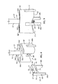
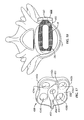
- a system for stabilizing a superior vertebra 12 relative to an inferior vertebra 14 in spine surgery, through a lateral access channel 16 (shown in phantom in Fig. 1A ).
- a system 10 having a plurality of separate parts and/or components that allow a surgeon to optimally align and/or attach a spinal plate to a vertebral spacer and/or one or more vertebrae, the system 10 is not limited to the inclusion of each component and may accomplish the intended function of stabilizing vertebrae 12, 14 using fewer or more components.
- the system 10 generally includes at least one interbody spacer 18, at least one vertebral fixation plate 20 and at least one alignment instrument 22.
- the system 10 is not limited to the inclusion of the above-indentified components, as more or fewer components may constitute "the system 10" to achieve the desired function of stabilizing adjacent vertebrae 12, 14 to permit fusion between the vertebrae 12, 14.
- the spacer 18, the plate 20 and the alignment instrument 22 are configured for use in lateral surgeries to the lumbar spine, such as extraforaminal posterior, trans-psoatic, and anterolateral approaches to fuse lumbar vertebrae. While the spacer 18, the plate 20 and the alignment instrument 22 are typically configured for lateral lumbar applications, the components of the system 10 may be adapted for a variety of spacer and plate configurations and indications, such as anterior cervical plates and spacers, lateral thoracic spacers, or the like.
- an exemplary embodiment of the spacer 18 is sized and shaped to generally fit entirely within a disc space DS ( Fig. 1A ) in an implanted configuration ( Figs. 1-3 , 14 , 16 and 18 ).
- the spacer 18 generally includes a distal or leading end 24, an opposing proximal or trailing end 26, a first or right side surface 28, an opposing second or left side surface 30, a third or top surface 29 and an opposing fourth or bottom surface 31.
- the first side surface 28 includes one ore more engagement features or slots 32 formed therein at least generally adjacent the proximal end 26.
- the proximal end 26 typically includes two spaced-apart slots 32 located on either side of a longitudinal axis of the spacer 18 that extend along the side surfaces 28, 30 and are exposed or open at the proximal end 26.
- the spacer 18 generally includes a first slot 32a on or in the first side surface 28 adjacent the proximal end 26 and a second slot 32b on or in the second side surface 30 adjacent the proximal end 26.
- the spacer 18 also typically includes a central opening 25 for housing bone graft material (not shown) and providing a path for boney fusion to occur through the spacer 18.
- the spacer 18 may be formed from a range of biocompatible materials, such as metals, including stainless steel and titanium, polymers, such as polyether ether ketone (PEEK), composite materials, allograft bone, or the like.
- the spacer 18 has a spacer length L S , as measured along the longitudinal axis of the spacer 18 from the furthest point of the proximal end 26 to the furthest point of the distal end 24, and a spacer width W S , as measured along an axis perpendicular to the longitudinal axis of the spacer 18 from the furthest point of the right side surface 28 to the furthest point of the left side surface 30.
- the spacer 18 also generally includes a spacer height H S , as measured along an axis perpendicular to the longitudinal axis from the highest point of the top surface 29 to the lowest point of the bottom surface 31.
- the spacer length L S is significantly greater than the spacer width W S , which are both greater than the spacer height H S .
- the spacer length L S may be approximately two or more times greater than the spacer width W S .
- the spacer length L S may be approximately thirty eight to fifty millimeters (38-50 mm) and the spacer width W S may be approximately eighteen to twenty millimeters (18-20 mm).
- the spacer 18 is not limited to having the above-described length and width ranges, and may include other appropriate footprints and various heights in the ranges including, but not limited to, seven to seventeen millimeters (7-17 mm) for the spacer height H S .
- the spacer 18 may be manufactured in other dimensions as well.
- the distal end 24 of the spacer 18 typically includes a tapered or bullet-shaped nose to ease insertion of the spacer 18 into the disc space DS between adjacent vertebrae 12, 14.
- one or both of the top and bottom surfaces 29, 31 of the spacer 120 are generally at least partially rough to engage the respective vertebrae 12, 14 to initially secure the spacer 18 to the vertebrae 12, 14.
- the entire top and bottom surfaces 29, 31 typically include a plurality of spaced-apart projections or teeth 27, which may be in the shape of a pyramid or sawtooth, for example.
- the teeth 27 may also be serrated to inhibit backing-out of the spacer 18 from the disc spacer DS.
- the teeth 27 may have, for example, a height of approximately one millimeter (1 mm).
- the top and bottom surfaces 29, 31 may further be convexly shaped along the spacer length L S to conform to the patient's anatomy. Alternatively or additionally, the top and bottom surfaces 29, 31 may be convex in both the anterior-posterior plane as well as in the sagittal plane. Further, the top and bottom surfaces 29, 31 may take on a lordotic or wedge-shape to generally adapt to the anatomic positioning of the adjacent vertebrae 12, 14. For example, the top and bottom surfaces 29, 31 may be formed with a radius of curvature of two hundred millimeters (200 mm) in the anterior-posterior plane and fifty millimeters (50 mm) in the sagittal plane, for example.
- Figs. 1-5 show the plate 20 in accordance with a first exemplary embodiment that is sized and shaped to be fixedly attach to at least one but typically both the superior and inferior vertebrae 12, 14 in the implanted configuration near the proximal end 26 of the spacer 18. Further, the plate 20 is generally configured to span the disc space DS into which the spacer 18 is implanted.
- the plate 20 includes a proximal or second surface 38 ( Fig. 4 ) and an opposing distal or first surface 40 ( Fig. 1A ).
- the distal surface 40 generally faces and/or engages at least a portion both the superior and inferior vertebrae 12, 14 in the implanted configuration and the spacer 20 has a predetermined thickness such that the distal or first surface 40 is spaced a predetermined distance from the proximal surface 38 of the spacer 18 in the implanted configuration.
- At least the distal surface 40 often includes a surface geometry that is configured to match the anatomy of the lateral aspects of the adjacent vertebrae 12, 14.
- at least the distal surface 40 is generally at least slightly concave in shape.
- the proximal surface 38 may be convexly shaped (see Figs. 1A-3 ), flat or planar.
- the plate 20 typically has at least one superior or first screw hole 34 and at least one inferior or second screw hole 36.
- the superior screw hole 34 includes a first or upper-left side screw hole 34a spaced a predetermined distance apart from a second or upper-right side screw hole 34b.
- the inferior screw hole 36 typically includes a third or lower-left side screw hole 36a spaced a predetermined distance apart from a fourth or lower-right side screw hole 36b.
- Each screw hole 34, 36 is sized and shaped to receive a bone anchor or screw 62 therethrough to secure the plate 20 to the adjacent vertebrae 12, 14 in the implanted configuration.
- Each screw hole 34, 36 may include a generally smooth interior wall, or the interior wall may include a series of screw threads (not shown) to engage threads of the bone anchor 62.
- the interior walls of the screw holes 34, 36 may also include features, which are known to those having ordinary skill in the art, to prevent back-out of the screws 62.
- the plate 20 typically includes a superior or first portion 42a, an opposite inferior or second portion 42b, and a middle portion or neck 42c located between the superior and inferior portions 42a, 42b. More specifically, the neck 42c is generally located between the superior and inferior screw holes, 34, 36.
- the neck 42c generally has a narrower width than either the superior or inferior portions 42a, 42b and that opposing sides of the plate 20 have a generally smooth contour or shape defining a concave surface at the neck 42c between the superior and inferior portions 42a, 42b.
- the plate 20 typically has a hour-glass or dog-bone shape when viewed from above or below (i.e., Fig.
- a superior side (i.e., top side) of the plate 20, proximate the superior portion 42a, and an inferior side (i.e., bottom side) of the plate 20, proximate the inferior portion 42b, are generally slightly curved, non-linear or concave.
- the concave shapes of the superior and inferior sides of the plate 20 are generally less pronounced or of a lesser degree than the concave shape of the opposing sides of the plate 20 proximate the neck 42c.
- the plate 20 may also include at least one hole or fastening mechanism 35 that is threaded and at least generally centrally disposed within the plate 20.
- the hole 35 typically extends at least partially through the proximal surface 38 of the plate 20 and extends completely through the plate 20 from the proximal or second surface 38 to the distal or first surface 40.
- the fastening mechanism 35 is not limited to a threaded hole 35 as is shown and described for the first exemplary embodiment and may be comprised of any mechanism that permits releasable securing of the plate 20 to the alignment instrument 22, such as clamps, magnetic devices, adhesives, prongs or other mechanisms that permit releasable engagement of the alignment instrument 22 to the plate 20.
- a first exemplary embodiment of the alignment instrument 22 includes a shaft 52 having a leading or distal end 44 and an opposing trailing or proximal end 46. As described in detail below, the leading end 44 of the shaft 52 is generally sized and shaped for removable attachment to the plate 20.
- the alignment instrument 22 typically includes an alignment prong 48 that extends outwardly therefrom and is generally sized and shaped to be positioned at least partially within the slot 32 of the spacer 18 in an insertion position such that the plate 20 is aligned with respect to the spacer 18 for attachment to the superior and inferior vertebrae 12, 14.
- a portion of the distal end 44 of the shaft 52 includes a series of screw threads or a securing mechanism 69 that are typically sized and shaped to matingly engage at least a portion of the hole or fastening mechanism 35 of the plate 20.
- the securing mechanism 69 is not limited to being comprised of the series of screw threads 69 and may be comprised of nearly any mechanism that permits releasable engagement of the shaft 52 to the plate 20.
- the securing mechanism may be comprised of a clamp, magnetic mechanism, adhesives, bayonet lock or any mechanism that permits releasable engagement of the shaft 52 to the plate 20.
- the alignment instrument 22 also includes an aiming device 50 located generally proximate or at the distal end 44 of the shaft 52 in an assembled configuration. More specifically, the distal end 44 of the shaft 52 is selectively, removably attachable to the aiming device 50.
- a distal surface 64 ( Fig. 9 ) of the aiming device 50 has at least generally the same or a mating version of the size, shape and cross-sectional area of the proximal surface 40 of the plate 20.
- a proximal surface 63 ( Figs. 8 and 9 ) of the aiming device 50 which generally opposes the distal surface 64 and is spaced a predetermined distance therefrom, has generally the same cross-sectional area as the distal surface 64 of the aiming device 50.
- the proximal surface 63 is generally flat or planar, but the size and shape of the proximal and distal surfaces 63, 64 are not limited to the specifications described above. Further, a thickness of the aiming device 50, as measured from the proximal to distal surfaces 63, 64 is substantially greater, such as by three times the thickness of the plate 20, as measured from the proximal to distal surfaces 38, 40 thereof. Similar to the plate 20, it is typical that the aiming device 50 includes a superior or first portion 66a, an opposite inferior or second portion 66b, and a middle portion or neck 66c. Like the plate 20, the aiming device 50 generally has an hour glass or dog-bone shape when viewed from above or below (generally Figs. 6 and 7 ). A passageway or opening 78, which is threaded, extends completely through the aiming device 50, such as from the proximal to the distal surfaces 63, 64, generally at the neck 22.
- the aiming device 50 generally includes at least one and often two spaced-apart and diametrically opposed extensions 77.
- one extension 77 is located proximate the superior portion 66a and a second extension 77 is located proximate the inferior portion 66b of the aiming device 50.
- at least a portion of each extension 77 extends beyond the distal surface 64 of the aiming device 50, such as by a distance generally equal to the thickness of the plate 20.
- the extensions 77 typically allow a surgeon or other user to properly align the aiming device 50 with respect to the plate 20 during assembly.
- each extension 77 is sized and shaped to engage or fit within the slightly concave shape of the superior and inferior sides of the plate 20 Additionally, the extensions 77 prevent rotational movement of the plate 20 with respect to the aiming device 50 when the shaft 52 is being inserted through the passageway 78 of the aiming device 50 and the hole 35 of the plate 20.
- the aiming device 50 of the alignment instrument 22 generally includes first, second, third and fourth alignment bores 56a-56d that extend from the proximal surface 63 to the distal surface 64 thereof.
- the first, second, third and fourth alignment bores 56a-56d are generally sized and shaped to align with the first, second, third and fourth screw holes 34a, 34b, 36a, 36b, respectively, of the plate 20 in the assembled configuration and the insertion position.
- the aiming device 50 also typically includes a guide groove 58 ( Fig. 8 ) proximate to or at the neck 66c and the distal surface 64 thereof.
- the guide groove 58 extends from the distal surface 64 of the aiming device 50 into an interior thereof and the entire width of the neck 42c.
- Two generally opposing flanges 68 extend inwardly into an interior of the guide groove 58 to define a narrowed portion of the guide groove 58.
- the aiming device 50 serves as a drill guide to ensure proper trajectory for drilling and insertion of the screws 62 to secure the plate 20 to the vertebrae 12, 14.
- the alignment bores 56a-56d of the aiming device 50 are generally located and angled to guide the screws 62 into generally the hardest or most dense portion of each vertebra 12, 14 to establish a secure connection with the vertebrae 12, 14.
- the alignment bores 56a-56d are positioned and oriented to guide each screw 62 into a region of each vertebra 12, 14 generally proximate the corners of the vertebrae 12, 14 and at or near the endplates of the vertebrae 12, 14, but not through the endplates such that a distal end of a screw 62 extends outwardly beyond the endplate.
- the alignment instrument 22 often includes a locating guide 54 that is sized and shaped to be selectably removably attachable to the aiming device 50.
- the locating guide 54 typically has a base arm 60 selectively mountable in the guide groove 58 of the aiming device 50.
- a pair of flanges 70 extend outwardly from opposing sidewalls of the base arm 60 and are sized and shaped to matingly engage with the flanges 68 of the guide grove 58 of the aiming device 50.
- a passageway or hole 71 which is threaded, extends from a proximal surface 72 to a distal surface 73 of the base arm 60.
- the passageway 71 is sized and shaped to selectively engage the screw threads 69 of the distal end 44 of the shaft 52.
- a lip 67 extends outwardly from a portion of the base arm 60 to prevent the locating guide 54 from sliding completely through the guide groove 58.
- the locating guide 54 may be integral and unitary with, and thus permanently attached to, the aiming device 50 and/or alignment instrument 22.
- a handle or knob 82 at the proximal end 46 of the shaft 52 typically allows the screw threads 69 at the distal end 44 to be advanced or withdrawn within the hole 35 of the plate 20, the passageway 78 of the aiming device 50, and the passageway 71 of the base arm 60 of the locating device 54.
- the locating guide 54 includes the alignment prong 48 thereon.
- the alignment prong 48 forms at least part of the locating guide 54.
- the alignment prong 48 includes a first alignment prong 48a spaced a predetermined distance apart from a second alignment prong 48b.
- the first and second alignment prongs 48a, 48b are typically sized and shaped to be positioned adjacent the neck 42 of the plate 20 in the insertion position.
- the first alignment prong 48a of the alignment instrument 22 is generally positioned at least partially within the first slot 32a of the spacer 18 and the second alignment prong 48b is positioned at least partially within the second slot 32b in the insertion position.
- the first and second alignment prongs 48a, 48b extend axially away from the first or distal surface 40 of the plate 20 approximately five to ten millimeters (5-10 mm), but are not so limited.
- the first and second alignment prongs 48a, 48b may extend a shorter distance, such as two millimeters (2 mm) or three millimeters (3 mm), from the distal surface 40 for relatively small spacers 18 or may extend a greater distance, such as eleven millimeters (11 mm) or twenty millimeters (20 mm), from the distal surface 40 to engage relatively long slots 32 in the spacer 18 or for relatively large spacers 18.
- the first and second alignment prongs 48a, 48b extend approximately seven and one-half millimeters (7.5 mm) away from the first or distal surface 40 of the plate 20 in the assembled configuration.
- the first and second alignment prongs 48a, 48b are not limited to extending from the first or distal surface 40 at the above-described distances and may extend from the distal surface 40 to nearly any length or distance that provides tactile feedback to the surgeon at the 52
- an incision is initially made in a patient's side and the access channel 16 is formed to provided access to the spinal disc space DS in need of repair.
- An at least partial discectomy is performed on the disc space DS and the spacer 18 is then inserted between the adjacent vertebrae 12, 14 with the distal end 24 entering the disc space DS first such that once the spacer 18 is in a desired position within the disc space DS, the proximal end 26 is proximate the incision and access channel 16.
- the distal end 44 of the shaft 52 is then coupled to the aiming device 50, and then the combined shaft and aiming device 50 is coupled to the plate 20, as described in detail above.
- the locating guide 54 is coupled to the combined aiming device 50 and shaft 52 before engagement with the plate 20, as described above, to form the assembled alignment instrument 22.
- the locating guide 54 may be coupled to the aiming device 50 before the aiming device 50 is coupled to the shaft 52.
- a single locating guide 54 may be used with each of the aiming devices 50 of a kit or each aiming device 50 may be associated with a different locating device 54.
- the plate 20 is coupled to the assembled alignment instrument 22, by inserting the distal end of the shaft 52 into the hole 35 of the plate 20.
- the assembled alignment instrument 22 is then used to insert the plate 20 down the access channel 16 and position the plate 20 with respect to the implanted spacer 18 by mating the alignment prongs 48a, 48b, which protrude beyond the distal surface 40 of the plate 20, with the slots 32a, 32b of the spacer 18.
- the plurality of screws 62 are driven into the adjacent vertebrae 12, 14 through the screw holes 34, 36 of the plate 20 and the alignment bores 56a-56d of the aiming device 50 using a screwdriver 65, drill or other driver instrument.
- the relatively long alignment bores 56a-56d of the aiming device 50 assist the surgeon in setting the trajectory of the screws 62 into the vertebrae 12, 14 to optimize position and alignment of the screws 62 relative to the spacer 18 and the vertebrae 12, 14.
- the shaft 52 is unscrewed from the hole 35 of the plate 20.
- the plate 20 is fixedly coupled to the vertebrae 12, 14.
- the assembled alignment instrument 22 is then pulled away from the plate 20 and the spacer 18 and the alignment prongs 48 are decoupled or disengaged from the slots 32 of the spacer 18.
- the alignment prongs 48 and the slots 32 generally do not lock to one another, but interface to provide tactile and visual feedback as to the positioning of the plate 20 with respect to the spacer 18. There is generally a gap G ( Fig.
- the gap G is formed by a curvature of at least the distal surface 40 of the plate 20 to match the natural anatomy of the vertebrae 12, 14 proximate the disc space DS.
- the gap G is provided to prevent contact between the spacer 18 and the plate 20, and is maintained by the stability of the spacer 18 within the disc space DS, i.e., the spacer 18 is fixed in position once implanted.
- the system 10 may include two ore more spaced-apart spacers 18 (i.e., a first spacer and a second spacer) positioned within the vertebral column and spaced therefrom, shown as a two-level surgery in Fig. 3 .
- the two spacers 18 may be substantially identical, such that either spacer 18 may be interchanged in a disc space DS without affecting the function and operability of the system 10.
- the system 10 may also include two or more spaced-apart plates 20 (i.e., a first plate and a second plate), of which the first plate 20 is fixedly attached to the superior and inferior 12, 14 vertebrae and the second plate 20 is fixedly attached to the superior vertebra 12 and a vertebra 15 adjacent the superior vertebra 12 opposite the inferior vertebra 14 in the implanted configuration near a proximal end 26 of the second spacer 18.
- the two plates 20 are substantially identical, such that either plate 20 may be interchanged without affecting the function and operability of the system 10.
- the system 10 may alternatively utilize a single two-level plate as would be apparent to one having ordinary skill in the art.
- the system 10 may include two or more separate aiming devices 50 (i.e., a first aiming device and a second aiming device) that are each removably mountable to one of the two plates 20, such that the first and third screw alignment bores 56a, 56b of the second aiming device 50 are aligned with superior and inferior screw holes 34, 36 of the second plate 20, respectively, when the second aiming device 50 is mounted to the second plate 20.
- Each aiming device 50 typically includes the guide groove 58.
- the two aiming devices 50 may be substantially identical, such that either aiming device 50 may be interchanged with one or more alignment instruments 22 without affecting the function and operability of the system 10.
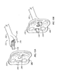
- the system 10 may include a plate kit including a plate case 74 for storing and/or transporting, for example, at least two and potentially a plurality of plates 20 of varying size and/or shape.
- the plate case 74 is shown holding five pairs of plates 20, but the system 10 is not so limited.
- the plate case 74 includes a base 75 and a lid (not shown) to enclose the plates 20 therein.
- One or more hinges 76 may allow the lid to be pivotally attached to the base 75.
- the base 75 includes a top row having a series of depressions or cut-outs that increase in size and/or shape from a left side of the top row to a right side of the top row.
- Each cut-out is sized and shaped to generally hold or surround one plate 20, for example.
- a lower row of the base 75 includes a series of depressions or cut-outs that are sized and shaped to generally surround one plate 20, for example.
- the plate case 74 is not so limited.
- the plate case 74 may include prongs (not shown) to secure the plates 20 therein
- the system 10 may include an aiming device kit including an aiming device case 79 for storing and/or transporting, for example, at least two and generally a plurality of aiming devices 50 of varying size and/or shape.
- the aiming device case 79 is shown holding five aiming devices 50 of increasing size and/or shape, but the system is not so limited.
- the aiming device case 79 includes a base 80 and a lid (not shown) to enclose the aiming devices 50 therein.
- One or more hinges 81 may allow the lid to be pivotally attached to the base 80.
- the base 80 may include a series of depressions or cut-outs that increase in size and/or shape from a left side of the base 80 to a right side of the base 80, in which each cut-out is sized and shaped to generally hold or surround one aiming device 50. Consecutive cut-outs generally hold or surround an incrementally sized and/or shaped aiming device 50, as compared to an adjacent cut-out, the aiming device case 78 is not so limited.
- a bottom interior surface of the base 80 may include one or more protrusions (not shown) that extend upwardly from the bottom interior surface and are sized and shaped to engage or surround at least a portion of each aiming device 50 to generally hold each aiming device 50 in place.
- the plate case 74 and aiming device case 79 may also be combined into a single case, that may also hold the remaining portions of the alignment instrument 22 and/or one or more spacers 18.
- the plate case 74, the aiming device case 79 and/or other components of the kit(s) are autoclaveable or adaptable to permit sterilization of the kit(s) following surgery.
- Figs. 12-14 show a second exemplary embodiment of the plate, generally designated 220, and the alignment instrument, generally designated 222, wherein like referenced numerals are utilized to indicate like elements throughout the several views.
- the reference numerals of the second exemplary embodiment are distinguishable from those of the first exemplary embodiment by the prefix "2", but otherwise indicate the same elements as in the first exemplary embodiment, except as otherwise specified.
- the plate 220 and the alignment instrument 222 of the second exemplary embodiment are generally, if not substantially, similar to those of the first exemplary embodiment.
- the plate 220 may include a proximal surface 238, an opposing distal surface 240, and at least one and a plurality of screw holes 234a, 234b, 236a, 236b.
- the plate 220 may include a centrally-located hole 235 that is threaded. Further, as seen in Figs. 13A and 13B , the alignment instrument 220 includes a rod or shaft 252 that is removably attachable to the plate 220. Additional similarities between the first and second exemplary embodiments are omitted herein for the sake of brevity or convenience, and the omission thereof is not limiting.
- the plate 220 includes a superior or first portion 242a, an opposite inferior or second portion 242b, and a middle portion or neck 242c located between the superior and inferior portions 242a, 242b. More specifically, the middle portion 242c is typically located between the superior screw holes 234a, 234b and the inferior screw holes 236a, 236b. In contrast to the first exemplary embodiment, the middle portion 242c has a width generally, if not exactly, equal to a width of the superior or inferior portions 242a, 242b. Thus, opposing sides of the plate 220 are generally straight or linear between the superior and inferior portions 242a, 242b.
- a superior side (i.e., top side) of the plate 220, proximate the superior portion 242a, and an interior side (i.e., bottom side) of the plate 220, proximate the inferior portion 242b, are at least generally curved, non-linear or concave.
- the plate 220 has a generally square shape when viewed from above or below (i.e., Fig. 12 ), but the plate 220 is not so limited.
- the plate 220 includes at least one and typically two-spaced apart throughholes 290.
- the throughholes 290 are proximate or within the middle portion 242c of the plate 220 and extend completely through the plate 220 from the proximal surface 238 to the distal surface 240.
- the throughholes 290 are each shown having a square or rectilinear cross-section and a cross-sectional area of each throughole 290 is shown as being less than that of any one of the screw holes 234a, 234b, 236a, 236b.
- the size and shape of the throughholes 290 may be modified.
- the through holes 290 are located on opposing sides of the hole 235.
- a distal end 244 of the shaft 252 of the alignment instrument 222 includes one or more engagement features, such as two spaced-apart alignment prongs 248.
- each prong 248 is sized and shaped to fit through or within one of the throughholes 290 of the plate 220 and engage or mate with a slot 32 of the spacer 18.
- each prong 248 is shown herein as having a rectangular shape, the prongs 248 are not so limited and may be formed in any size and shape that is capable of engaging a portion of the plate 220 (such as throughholes 290) and the spacer 18 (such as slot 32).
- the concave shape of the superior and inferior sides of the plate 220 are sized to receive the extensions 77 of the aiming device 50 of the first exemplary embodiment.
- the plate 220 of the second exemplary embodiment may be used with either the alignment instrument 222 of the second exemplary embodiment or the alignment instrument 22 of the first exemplary embodiment.
- Figs. 15 and 16 show a third exemplary embodiment of the plate, generally designated 320, wherein like referenced numerals are utilized to indicate like elements throughout the several views.
- the reference numerals of the third exemplary embodiment are distinguishable from those of the first exemplary embodiment by the prefix "3", but otherwise indicate the same elements as in the first exemplary embodiment, except as otherwise specified.
- the plate 320 of the third exemplary embodiment is substantially similar to that of the second exemplary embodiment.
- the plate 320 includes a proximal surface 338, an opposing distal surface 340, and at least one and generally a plurality of screw holes 334a, 334b, 336a, 336b.
- the plate 320 may also include centrally-located hole 335 that is threaded. Additional similarities between the third and second exemplary embodiments are omitted herein for the sake of brevity or convenience, and the omission thereof is not limiting.
- the plate 320 includes a superior or first portion 342a, an opposite inferior or second portion 342b, and a middle portion 342c located at least between the superior and inferior portions 342a, 342b. More specifically, the middle portion 342c is located between the superior screw holes 334a, 334b and the inferior screw holes 336a, 336b. Similar to the first exemplary embodiment, the middle portion 342c has a smaller or narrower width than either the superior or inferior portions 342a, 342b and that opposing sides of the plate 320 have a generally smooth contour or shape defining a concave surface at the middle portion 342c between the superior and inferior portions 342a, 342b.
- a superior side (i.e., top side) of the plate 320, proximate the superior portion 342a, and an interior side (i.e., bottom side) of the plate 320, proximate the inferior portion 342b, are generally slightly curved, non-linear or concave.
- the concave shape of the superior and inferior sides of the plate 320 are generally less pronounced or of a lesser degree than the concave shape of the opposing sides of the plate 320.
- the distal surface 340 of the plate 320 typically includes a tab 392 that extends or protrudes outwardly therefrom.
- the tab 392 extends generally across the entire width of the middle portion 342c of the plate 320 and completely surrounds the hole 335 on the distal surface 340. Further, in the present embodiment, the tab 392 extends outwardly from the distal surface 340 a uniform distance across the width of the middle portion 342c.
- the tab 392 is sized and shaped to locate the cranial and caudal aspects of the vertebral body endplate rims and position the plate 320 with respect to the spacer 18 relative to the disc space DS. While it is typical that the plate 320 is used in conjunction with the alignment instrument 22 of the first exemplary embodiment, the plate 320 is not so limited.
- Figs. 17 and 18 show a fourth exemplary embodiment of the plate, generally designated 420, wherein like referenced numerals are utilized to indicate like elements throughout the several views.
- the reference numerals of the fourth exemplary embodiment are distinguishable from those of the first exemplary embodiment by the prefix "4", but otherwise indicate the same elements as in the first exemplary embodiment, except as otherwise specified.
- the plate 420 of the fourth exemplary embodiment is substantially similar to that of at least the second and third exemplary embodiments.
- the plate 420 includes a proximal surface 438, an opposing distal surface 440, and at least one and potentially a plurality of screw holes 434a, 434b, 436a, 436b.
- the plate 420 may also include a centrally-located hole 435 that is threaded. Additional similarities between the fourth and second or third exemplary embodiments are omitted herein for the sake of brevity or convenience, and the omission thereof is not limiting.
- the plate 420 includes a superior or first portion 442a, an opposite inferior or second portion 442b, and a middle portion 442c located at least between the superior and inferior portions 442a, 442b. More specifically, the middle portion 442c is generally located between the superior screw holes 434a, 434b and the inferior screw holes 436a, 436b. Similar to the second exemplary embodiment, the middle portion 442c has a width generally, if not exactly, equal to a width of the superior or inferior portions 442a, 442b. Thus, opposing sides of the plate 420 are generally straight or linear between the superior and inferior portions 442a, 442b.
- a superior side (i.e., top side) of the plate 420, proximate the superior portion 442a, and an interior side (i.e., bottom side) of the plate 420, proximate the inferior portion 442b, are at least slightly, generally curved, non-linear or concave.
- the distal surface 440 of the plate 420 includes at least one and typically two-spaced apart internal tabs 493 that are integrally formed with the plate 420.
- the tabs 493 extend axially from the distal surface 440 relative to an insertion direction and away from the distal surface 440.
- the tabs 493 are located on either side of a depression or concave area 494 that completely surrounds the hole 435 on the distal surface 440.
- the tabs 493 are generally located on or within the middle portion 442c and at opposing outer-most sides thereof.
- each tab 493 includes an interior surface that defines a smooth or seamless transition to the concave area 494.
- the tabs 493 are generally sized and shaped to mate with the slots 32 on the proximal end 26 of the spacer 18 and the concave area 494 is sized and shaped to surround or engage at least a portion of the proximal end 26 of the spacer 18.
- the tabs 493 and concave area 494 are utilized to engage the spacer 18 to position and orient the spacer 18 and plate 420 relative to each other and the plate 420 relative to the vertebrae 12, 14.
- the plate 420 is generally used in conjunction with the alignment instrument 22 of the first exemplary embodiment, but is not so limited and may be utilized with alternative insertion instruments (not shown) for aligning the plate 420 with the spacer 18 and/or the patient's vertebrae 12, 14.
- a method for stabilizing the superior vertebra 12 relative to the inferior vertebra 14 in spine surgery through the lateral access channel 16 includes inserting the spacer 18 into the disc space DS between the superior and inferior vertebrae 12, 14.
- the spacer 18 has the distal end 24 and the proximal end 26, the first side surface 28 and the second side surface 30, wherein the first side surface 28 has the slot 32 formed therein adjacent the proximal end 26, as described in detail above.
- the method further includes attaching a leading end 44, 244 of an alignment instrument 22, 222 to a plate 20, 220, 320, 420, an alignment prong 48, 248 extending outwardly from the leading end 44, 244 of the alignment instrument 22, 222 and beyond a distal surface 40, 240, 340, 440 of the plate 20, 220, 320, 420 when the leading end 44, 244 and the plate 20, 220, 320, 420 are attached.
- the alignment instrument 22 may include the aiming device 50, the removable shaft 52 and the locating guide 54, as described above. Further, the locating guide 54 may include the alignment prong 22 thereon.
- the method may also include inserting at least a portion of the removable shaft 52 into the opening 78, 71, 35 into each of the aiming device 50, the locating guide 54 and the plate 20 to align the aiming device 50 and the locating guide 54 with the plate 20.
- the method typically includes using the alignment instrument 22, 222 to align the plate 20, 220, 320, 420 with respect to the spacer 18 by inserting at least a portion of the alignment prong 48, 248 into at least a portion of the slot 32 of the spacer 18.
- the method further includes inserting at least one screw 62 using a conventional screwdriver 65 ( Fig. 2 ) or the like through the plate 20, 220, 320, 420 and into the superior vertebra 12 and inserting at least another screw 62 through the plate 20, 220, 320, 420 and into the inferior vertebra 14 to fixedly attach the plate 20, 220, 320, 420 to the superior and inferior vertebrae 12, 14.
- temporary fixation screws may be used to hold the plate 20, 220, 320, 420 in place while final preparation and screw 62 insertion is performed.
- the cortical shell of the vertebrae 12, 14, 15 may be perforated using an awl (not shown) prior to screw 62 insertion.
- the shaft 52, 252 of the alignment instrument 20, 222 may serve as a counter-torque handle.
- the method also typically includes separating and withdrawing the leading end 44, 244 of the alignment instrument 22, 222 from the plate 20, 220, 320, 420.
- the method may also include removing the shaft 25 from the opening 35 in the plate 20 to separate the aiming device 50 and the locating guide 54 from the plate 20 and removing the alignment prong 48 from the slot 32 to allow withdrawal of the leading end 44 of the alignment instrument 22 from the plate 20.
Claims (14)
- Système (10) destiné à stabiliser une vertèbre supérieure (12) par rapport à une vertèbre inférieure (14), la vertèbre supérieure (12) et la vertèbre inférieure (14) présentant une entretoise (18) positionnée entre elles, le système (10) comprenant :une plaque (20) présentant une première surface (40) configurée pour s'apparier avec les vertèbres supérieure et inférieure (12), (14), et une seconde surface (38) généralement face à la première surface (40), la plaque (20) présentant un premier trou (34) entre les première et seconde surfaces (40, 38) et un deuxième trou (36) entre les première et seconde surfaces (40,38), le premier trou (34) étant configuré pour se trouver au-dessus de la vertèbre supérieure (12), et le deuxième trou (36) étant configuré pour se trouver au-dessus de la vertèbre inférieure (14), la plaque (20) incluant en outre un mécanisme d'attache (35), etun instrument d'alignement (22) présentant une partie de tête (44) et une partie de queue (46), la partie de tête (44) comprenant un mécanisme de fixation (69) configuré pour être attaché de manière amovible sur le mécanisme d'attache (35) de la plaque (20), l'instrument d'alignement (22) incluant en outre une patte d'alignement (48) s'étendant en direction axiale à partir de la partie de tête (44) de l'instrument d'alignement (22) de telle sorte que la patte d'alignement (48) s'étende au-delà de la première surface (40) de la plaque (20) lorsque la plaque (20) est attachée au mécanisme de fixation (69), caractérisé en ce que la patte d'alignement (48) de l'instrument d'alignement (22) est configurée pour s'apparier avec une fente (32), définie par l'entretoise (18), de manière à positionner la plaque (20) par rapport à l'entretoise implantée (18) en appariant la patte d'alignement (48) avec la fente (32) de l'entretoise (18),la patte d'alignement (48) fournissant des informations tactiles à la partie de queue (46) de l'instrument d'alignement (22) à utiliser pour le positionnement de la plaque (20) par rapport à l'entretoise implantée (18) et aux vertèbres supérieure et inférieure (12), (14).
- Système (10) selon la revendication 1, dans lequel la patte d'alignement (48) s'étend approximativement cinq à dix millimètres (5-10 mm) au-delà de la première surface (40) de la plaque (20) lorsque la plaque (20) est attachée au mécanisme de fixation (69) de l'instrument d'alignement (22).
- Système (10) selon la revendication 1 ou 2, dans lequel l'instrument d'alignement (22) comprend des première et seconde pattes d'alignement (48a), (48b) s'étendant chacune approximativement cinq à dix millimètres (5-10 mm) au-delà de la première surface (40) de la plaque (20) lorsque la plaque (20) est attachée au mécanisme d'attache (35) de l'instrument d'alignement (22), les pattes d'alignement (48a, (48b) de l'instrument d'alignement (22) étant configurées pour s'apparier avec des première et seconde fentes (32a), (32b) définies par l'entretoise (18), alignant de ce fait la plaque (20) par rapport à l'entretoise (18) dans au moins deux dimensions.
- Système (10) selon la revendication 3, dans lequel la plaque (20) est configurée de telle sorte que l'alignement de la plaque (20) avec l'entretoise (18) aligne en outre le premier trou (34) pour qu'il se trouve au-dessus de la vertèbre supérieure (12), et le deuxième trou (36) pour qu'il se trouve au-dessus de la vertèbre inférieure (14).
- Système (10) selon l'une quelconque des revendications 1 à 4, dans lequel l'instrument d'alignement (22) inclut un premier dispositif de visée (50), et de préférence un arbre (52) pouvant être monté de manière amovible sur le premier dispositif de visée (50) et la patte d'alignement (48), dans lequel de préférence, la patte d'alignement (48) est raccordée, de manière à pouvoir être détachée, au premier dispositif de visée (50).
- Système (10) selon la revendication 5, dans lequel la patte d'alignement (48) s'étend en direction axiale à partir d'un bras de base (60), le premier dispositif de visée (50) incluant une première rainure de guidage (58), le bras de base (60) pouvant être monté, de manière à pouvoir être détaché, à l'intérieur de la première rainure de guidage (58),
le système comprenant en outre et de préférence :un second dispositif de visée (50) avec une seconde rainure de guidage, le bras de base (60) pouvant être monté de manière sélective dans la première rainure de guidage (58) et la seconde rainure de guidage (58). - Système (10) selon l'une quelconque des revendications 1 à 4, dans lequel l'instrument d'alignement (22) inclut un premier dispositif de visée (50), un arbre amovible (52) et un guide de positionnement (54), la patte d'alignement (48) comprenant une première patte d'alignement (48) et une seconde patte d'alignement (48) qui sont associées au guide de positionnement (54).
- Système (10) selon l'une quelconque des revendications 1 à 7, dans lequel le premier trou (34) comprend des premier et deuxième trous de vis (34a), (34b), et le deuxième trou (36) comprend des troisième et quatrième trous de vis (36a), (36b), la plaque (20) incluant un col (42c) entre les premier et deuxième trous (34, (36),
dans lequel, de préférence, l'instrument d'alignement (22) inclut un dispositif de visée (50) présentant des premier, deuxième, troisième et quatrième alésages d'alignement (56a), (56b), (56c), (56d), un arbre amovible (52), et un guide de positionnement (54), les premier, deuxième, troisième et quatrième alésages d'alignement (56a), (56b), (56c), (56d) étant alignés avec les premier, deuxième, troisième et quatrième trous de vis (34a), (34b), (36a), (36b) dans une position d'insertion. - Système (10) selon l'une quelconque des revendications 1 à 8, dans lequel la patte d'alignement (48) inclut des première et seconde pattes d'alignement (48a), (48b), les première et seconde pattes d'alignement (48a), (48b) étant positionnées à proximité d'un col de la plaque (20) dans la position d'insertion.
- Système (10) selon l'une quelconque des revendications 1 à 9, dans lequel la première surface (40) de la plaque (20) est configurée de manière à être espacée de l'entretoise (18) dans la position implantée.
- Système (10) selon la revendication 1, comprenant en outre :une entretoise (18) présentant une partie distale (24), une partie proximale (26), une première surface latérale (28), et une seconde surface latérale (30), la première surface latérale (28) présentant une fente (32) formée à l'intérieur d'elle de manière adjacente à la partie proximale (26), l'entretoise (18) étant configurée pour un positionnement entre les vertèbres supérieure et inférieure (12), (14) et présentant une longueur d'entretoise LS et une largeur d'entretoise WS, la longueur d'entretoise LS étant supérieure à la largeur d'entretoise WS ;dans lequel la plaque (20) présente une languette (493) s'étendant en direction axiale vers l'extérieur à partir de la première surface (40), la languette (493) étant configurée pour être reçue dans la fente (32) lorsque la plaque (20) est montée sur les vertèbres supérieure et inférieure (12), (14).
- Système (10) selon la revendication 11, dans lequel la languette (493) comprend deux languettes internes espacées l'une de l'autre (493) et formées d'un seul tenant avec la plaque (20),
dans lequel, de préférence, les deux languettes internes espacées l'une de l'autre (493) sont positionnées au niveau d'une partie intermédiaire (442c) entre une partie supérieure (442a) et une partie inférieure (442b) de la plaque (20), les languettes (493) s'entendant à une distance de sept virgule cinq millimètres (7,5 mm) approximativement en direction axiale de la première surface (40). - Système (10) selon la revendication 11, dans lequel la languette (493) est positionnée entre des premier et deuxième trous (34), (36).
- Système (10) selon l'une quelconque des revendications 11 à 13, dans lequel le premier trou (34) comprend une série de premiers trous de vis (34a), (34b) et le deuxième trou (36) comprend une série de deuxièmes trous de vis (36a), (36b).
Applications Claiming Priority (3)
| Application Number | Priority Date | Filing Date | Title |
|---|---|---|---|
| US16054409P | 2009-03-16 | 2009-03-16 | |
| US24170509P | 2009-09-11 | 2009-09-11 | |
| PCT/US2010/027301 WO2010107692A1 (fr) | 2009-03-16 | 2010-03-15 | Système et procédé de stabilisation de vertèbres dans une chirurgie rachidienne par le biais d'un canal d'accès latéral |
Publications (2)
| Publication Number | Publication Date |
|---|---|
| EP2408381A1 EP2408381A1 (fr) | 2012-01-25 |
| EP2408381B1 true EP2408381B1 (fr) | 2014-11-12 |
Family
ID=42111314
Family Applications (1)
| Application Number | Title | Priority Date | Filing Date |
|---|---|---|---|
| EP10710717.9A Active EP2408381B1 (fr) | 2009-03-16 | 2010-03-15 | Système de stabilisation de vertèbres dans une chirurgie rachidienne par le biais d'un canal d'accès latéral |
Country Status (5)
| Country | Link |
|---|---|
| US (1) | US9375237B2 (fr) |
| EP (1) | EP2408381B1 (fr) |
| CN (1) | CN102883668B (fr) |
| BR (1) | BRPI1008924A2 (fr) |
| WO (1) | WO2010107692A1 (fr) |
Families Citing this family (63)
| Publication number | Priority date | Publication date | Assignee | Title |
|---|---|---|---|---|
| US9795367B1 (en) | 2003-10-17 | 2017-10-24 | Nuvasive, Inc. | Surgical access system and related methods |
| US20080161929A1 (en) | 2006-12-29 | 2008-07-03 | Mccormack Bruce | Cervical distraction device |
| US9005288B2 (en) | 2008-01-09 | 2015-04-14 | Providence Medical Techonlogy, Inc. | Methods and apparatus for accessing and treating the facet joint |
| EP2328492B1 (fr) | 2008-06-06 | 2018-03-28 | Providence Medical Technology, Inc. | Implants pour articulation facettaire et outils de mise en place |
| US8267966B2 (en) | 2008-06-06 | 2012-09-18 | Providence Medical Technology, Inc. | Facet joint implants and delivery tools |
| US8361152B2 (en) | 2008-06-06 | 2013-01-29 | Providence Medical Technology, Inc. | Facet joint implants and delivery tools |
| US9333086B2 (en) | 2008-06-06 | 2016-05-10 | Providence Medical Technology, Inc. | Spinal facet cage implant |
| US11224521B2 (en) | 2008-06-06 | 2022-01-18 | Providence Medical Technology, Inc. | Cervical distraction/implant delivery device |
| US10842642B2 (en) | 2009-04-16 | 2020-11-24 | Nuvasive, Inc. | Methods and apparatus of performing spine surgery |
| US10098674B2 (en) | 2009-10-22 | 2018-10-16 | Nuvasive, Inc. | System and method for posterior cervical fusion |
| WO2011050140A1 (fr) | 2009-10-22 | 2011-04-28 | Blue Fury Consulting, L.L.C. | Système et techniques de fusion cervicale postérieure |
| WO2012026981A1 (fr) | 2010-08-23 | 2012-03-01 | Nuvasive, Inc. | Système d'accès chirurgical et procédés afférents |
| US9220535B2 (en) * | 2010-10-26 | 2015-12-29 | Christian Röbling | Process for introducing a stabilizing element into a vertebral column |
| US8940030B1 (en) | 2011-01-28 | 2015-01-27 | Nuvasive, Inc. | Spinal fixation system and related methods |
| US8496689B2 (en) * | 2011-02-23 | 2013-07-30 | Farzad Massoudi | Spinal implant device with fusion cage and fixation plates and method of implanting |
| US8454694B2 (en) * | 2011-03-03 | 2013-06-04 | Warsaw Orthopedic, Inc. | Interbody device and plate for spinal stabilization and instruments for positioning same |
| US20120259363A1 (en) * | 2011-04-08 | 2012-10-11 | Kyphon Sarl | Viscoelastic lumbar-sacral implant |
| US9622759B2 (en) * | 2011-04-21 | 2017-04-18 | DePuy Synthes Products, Inc. | Spline oriented indexing guide |
| US20140207239A1 (en) | 2011-09-09 | 2014-07-24 | Spine Wave, Inc. | Lateral approach expandable spinal implant and method |
| US11123117B1 (en) | 2011-11-01 | 2021-09-21 | Nuvasive, Inc. | Surgical fixation system and related methods |
| US9066701B1 (en) | 2012-02-06 | 2015-06-30 | Nuvasive, Inc. | Systems and methods for performing neurophysiologic monitoring during spine surgery |
| US9655505B1 (en) | 2012-02-06 | 2017-05-23 | Nuvasive, Inc. | Systems and methods for performing neurophysiologic monitoring during spine surgery |
| EP2628466B1 (fr) | 2012-02-17 | 2017-04-05 | Medacta International S.A. | Implant intervertébral avec système de fixation amélioré pour plaque de fixation |
| US9750616B2 (en) | 2012-02-17 | 2017-09-05 | Spinal Elements, Inc. | Interbody fusion device |
| US10076364B2 (en) | 2012-06-29 | 2018-09-18 | K2M, Inc. | Minimal-profile anterior cervical plate and cage apparatus and method of using same |
| EP3345576B1 (fr) * | 2012-06-29 | 2020-09-30 | DePuy Synthes Products, LLC | Implant vertébral à introduction latérale |
| USD732667S1 (en) | 2012-10-23 | 2015-06-23 | Providence Medical Technology, Inc. | Cage spinal implant |
| US9757067B1 (en) | 2012-11-09 | 2017-09-12 | Nuvasive, Inc. | Systems and methods for performing neurophysiologic monitoring during spine surgery |
| AU2014270043B2 (en) * | 2013-01-16 | 2018-07-26 | Retrospine Pty Ltd | Spinal plate selection and positioning system |
| JP6373878B2 (ja) | 2013-02-14 | 2018-08-15 | メダクタ・インターナショナル・ソシエテ・アノニム | 固定プレートの形状を改善した椎間インプラント |
| EP3062747B1 (fr) | 2013-10-28 | 2022-06-08 | Jace Medical, LLC | Dispositifs et systèmes de fixation orthopédique |
| JP2017520357A (ja) | 2014-05-28 | 2017-07-27 | プロビデンス メディカル テクノロジー インコーポレイテッド | 外側塊固定システム |
| WO2016029008A1 (fr) | 2014-08-20 | 2016-02-25 | Jace Medical, Llc | Dispositifs de mise en place d'implant et procédés |
| USD779065S1 (en) | 2014-10-08 | 2017-02-14 | Nuvasive, Inc. | Anterior cervical bone plate |
| CA2917503A1 (fr) | 2015-01-14 | 2016-07-14 | Stryker European Holdings I, Llc | Implant vertebral dote de capacites de distribution de fluide |
| AU2016200179B2 (en) | 2015-01-14 | 2020-09-17 | Stryker European Operations Holdings Llc | Spinal implant with porous and solid surfaces |
| US10342678B2 (en) | 2015-02-02 | 2019-07-09 | Spinal Elements, Inc. | Interbody implant inserter |
| CA2930123A1 (fr) | 2015-05-18 | 2016-11-18 | Stryker European Holdings I, Llc | Implants partiellement resorbables et methodes |
| WO2016205870A1 (fr) * | 2015-06-23 | 2016-12-29 | Prism Surgical Designs Pty Ltd | Système de fixation vertébrale |
| WO2017175024A2 (fr) * | 2015-08-31 | 2017-10-12 | Retrospine Pty Ltd | Système de sélection et de positionnement de plaque vertébrale |
| CN108289689A (zh) | 2015-10-13 | 2018-07-17 | 普罗维登斯医疗技术公司 | 脊柱关节植入物输送装置和系统 |
| USD841165S1 (en) | 2015-10-13 | 2019-02-19 | Providence Medical Technology, Inc. | Cervical cage |
| US11246624B2 (en) * | 2015-11-06 | 2022-02-15 | Joint Development, Llc | Broach holder tool with reduced rasp moment |
| US10433978B2 (en) * | 2016-05-31 | 2019-10-08 | Bullard Spine, Llc | Systems and methods for adjacent vertebral fixation |
| TW201806562A (zh) | 2016-06-28 | 2018-03-01 | 普羅維登斯醫療科技公司 | 脊椎植入體及其使用方法 |
| USD887552S1 (en) | 2016-07-01 | 2020-06-16 | Providence Medical Technology, Inc. | Cervical cage |
| JP6700135B2 (ja) * | 2016-07-25 | 2020-05-27 | 日本特殊陶業株式会社 | 椎体スペーサ |
| AU2017100001A4 (en) | 2016-07-26 | 2017-02-23 | Prism Surgical Designs Pty Ltd | A Spinal Fixation and Guidance System |
| WO2018035175A1 (fr) * | 2016-08-15 | 2018-02-22 | In Queue Innovations, Llc | Dispositif, système et procédés de fusion osseuse |
| EP3515368A1 (fr) | 2016-09-20 | 2019-07-31 | DePuy Synthes Products, Inc. | Implant intervertébral |
| JP7039614B2 (ja) * | 2016-12-27 | 2022-03-22 | デピュイ・シンセス・プロダクツ・インコーポレイテッド | 骨プレート締結システム |
| US11871968B2 (en) | 2017-05-19 | 2024-01-16 | Providence Medical Technology, Inc. | Spinal fixation access and delivery system |
| EP3459502A1 (fr) | 2017-09-20 | 2019-03-27 | Stryker European Holdings I, LLC | Implants vertébraux |
| WO2019136263A1 (fr) | 2018-01-04 | 2019-07-11 | Providence Medical Technology, Inc. | Vis à facettes et dispositif de pose |
| US11744619B2 (en) | 2018-04-06 | 2023-09-05 | K2M, Inc. | Faceted bone plate |
| US11090068B2 (en) * | 2018-11-08 | 2021-08-17 | Ctl Medical Corporation | Vertebral body reaming method |
| US11779378B2 (en) * | 2019-01-11 | 2023-10-10 | Medcom Advisors, Llc | Self-aligning plating system and method |
| USD933230S1 (en) | 2019-04-15 | 2021-10-12 | Providence Medical Technology, Inc. | Cervical cage |
| AU2020270065A1 (en) | 2019-05-07 | 2022-01-06 | Spinal Elements, Inc. | Cervical plate and inserter |
| USD911525S1 (en) | 2019-06-21 | 2021-02-23 | Providence Medical Technology, Inc. | Spinal cage |
| US11806030B1 (en) * | 2019-10-16 | 2023-11-07 | The Regents Of The University Of Colorado, A Body Corporate | Trial sizer for alignment of pilot holes |
| USD945621S1 (en) | 2020-02-27 | 2022-03-08 | Providence Medical Technology, Inc. | Spinal cage |
| FR3126182A1 (fr) * | 2021-08-18 | 2023-02-24 | Univ Poitiers | Outillage de pose d’implants discaux intervertebraux |
Family Cites Families (107)
| Publication number | Priority date | Publication date | Assignee | Title |
|---|---|---|---|---|
| US3426364A (en) | 1966-08-25 | 1969-02-11 | Colorado State Univ Research F | Prosthetic appliance for replacing one or more natural vertebrae |
| US3661411A (en) * | 1970-11-16 | 1972-05-09 | Jewell Mfg Co | Joint construction |
| SE391122B (sv) | 1971-01-25 | 1977-02-07 | Cutter Lab | Protes i form av en ryggradsbroskskiva och forfarande for framstellning derav |
| GB2068734B (en) | 1980-02-06 | 1983-11-23 | Saratov Nii Travmatol I Ortope | Hip endoprosthesis |
| CA1146301A (fr) | 1980-06-13 | 1983-05-17 | J. David Kuntz | Disque intervertebral prosthetique |
| DE3106917C2 (de) | 1981-02-25 | 1984-04-05 | Schuett Und Grundei Gmbh Medizintechnische Fabrikation, 2400 Luebeck | Verfahren zur Herstellung eines Implantates als Knochenersatz |
| US4394370A (en) | 1981-09-21 | 1983-07-19 | Jefferies Steven R | Bone graft material for osseous defects and method of making same |
| US4450591A (en) | 1981-12-10 | 1984-05-29 | Rappaport Mark J | Internal anti-proratory plug assembly and process of installing the same |
| US4545374A (en) | 1982-09-03 | 1985-10-08 | Jacobson Robert E | Method and instruments for performing a percutaneous lumbar diskectomy |
| FR2570594B1 (fr) | 1984-09-26 | 1989-02-24 | Kehr Pierre | Prothese vertebrale, en particulier pour vertebres cervicales |
| US4627853A (en) | 1985-05-29 | 1986-12-09 | American Hospital Supply Corporation | Method of producing prostheses for replacement of articular cartilage and prostheses so produced |
| US4599086A (en) | 1985-06-07 | 1986-07-08 | Doty James R | Spine stabilization device and method |
| US4743256A (en) | 1985-10-04 | 1988-05-10 | Brantigan John W | Surgical prosthetic implant facilitating vertebral interbody fusion and method |
| US4834757A (en) | 1987-01-22 | 1989-05-30 | Brantigan John W | Prosthetic implant |
| US4714469A (en) | 1987-02-26 | 1987-12-22 | Pfizer Hospital Products Group, Inc. | Spinal implant |
| CH672589A5 (fr) | 1987-07-09 | 1989-12-15 | Sulzer Ag | |
| CH672588A5 (fr) | 1987-07-09 | 1989-12-15 | Sulzer Ag | |
| US5116374A (en) | 1989-03-02 | 1992-05-26 | Regen Corporation | Prosthetic meniscus |
| GB8718627D0 (en) | 1987-08-06 | 1987-09-09 | Showell A W Sugicraft Ltd | Spinal implants |
| US4829152A (en) | 1987-11-16 | 1989-05-09 | Rostoker, Inc. | Method of resistance welding a porous body to a substrate |
| DE3809793A1 (de) | 1988-03-23 | 1989-10-05 | Link Waldemar Gmbh Co | Chirurgischer instrumentensatz |
| US5047058A (en) | 1988-04-08 | 1991-09-10 | Smith & Nephew Richards, Inc. | System of inserts for the tibial component of a knee prosthesis |
| US5484437A (en) | 1988-06-13 | 1996-01-16 | Michelson; Gary K. | Apparatus and method of inserting spinal implants |
| US5772661A (en) | 1988-06-13 | 1998-06-30 | Michelson; Gary Karlin | Methods and instrumentation for the surgical correction of human thoracic and lumbar spinal disease from the antero-lateral aspect of the spine |
| US5609635A (en) | 1988-06-28 | 1997-03-11 | Michelson; Gary K. | Lordotic interbody spinal fusion implants |
| CA1333209C (fr) | 1988-06-28 | 1994-11-29 | Gary Karlin Michelson | Implants artificiels pour la soudure osseuse intervertebrale |
| US4872452A (en) | 1989-01-09 | 1989-10-10 | Minnesota Mining And Manufacturing Company | Bone rasp |
| US5290558A (en) | 1989-09-21 | 1994-03-01 | Osteotech, Inc. | Flowable demineralized bone powder composition and its use in bone repair |
| US5006120A (en) | 1989-10-10 | 1991-04-09 | Carter Peter R | Distal radial fracture set and method for repairing distal radial fractures |
| DE8912648U1 (fr) | 1989-10-23 | 1990-11-22 | Mecron Medizinische Produkte Gmbh, 1000 Berlin, De | |
| US5192327A (en) | 1991-03-22 | 1993-03-09 | Brantigan John W | Surgical prosthetic implant for vertebrae |
| JPH06503155A (ja) | 1991-06-25 | 1994-04-07 | ジンテーズ アクチエンゲゼルシャフト,クール | 固着要素 |
| US5306307A (en) | 1991-07-22 | 1994-04-26 | Calcitek, Inc. | Spinal disk implant |
| US5258031A (en) | 1992-01-06 | 1993-11-02 | Danek Medical | Intervertebral disk arthroplasty |
| US5201736A (en) | 1992-01-13 | 1993-04-13 | Strauss Sorrell I | Maxillofacial bone clamp |
| US5282861A (en) | 1992-03-11 | 1994-02-01 | Ultramet | Open cell tantalum structures for cancellous bone implants and cell and tissue receptors |
| US5766251A (en) | 1992-03-13 | 1998-06-16 | Tomihisa Koshino | Wedge-shaped spacer for correction of deformed extremities |
| DE4208115A1 (de) | 1992-03-13 | 1993-09-16 | Link Waldemar Gmbh Co | Bandscheibenendoprothese |
| US5306309A (en) | 1992-05-04 | 1994-04-26 | Calcitek, Inc. | Spinal disk implant and implantation kit |
| US5324290A (en) | 1992-09-24 | 1994-06-28 | Danek Medical, Inc. | Anterior thoracolumbar plate |
| US6001099A (en) | 1998-06-08 | 1999-12-14 | Huebner; Randall J. | Bone plate with varying rigidity |
| US6066175A (en) | 1993-02-16 | 2000-05-23 | Henderson; Fraser C. | Fusion stabilization chamber |
| FR2703580B1 (fr) | 1993-03-03 | 1997-10-17 | Gilles Robert | Cage intersomatique cervicale. |
| DE4423826B4 (de) | 1993-07-07 | 2007-01-04 | Pentax Corp. | Keramische Wirbelprothese |
| FR2708461B1 (fr) | 1993-08-06 | 1995-09-29 | Advanced Technical Fabrication | Implant intersomatique pour colonne vertébrale. |
| DE4328690B4 (de) | 1993-08-26 | 2006-08-17 | SDGI Holdings, Inc., Wilmington | Zwischenwirbelimplantat zur Wirbelkörperverblockung und Implantationsinstrument zum Positionieren des Zwischenwirbelimplantats |
| US5425772A (en) | 1993-09-20 | 1995-06-20 | Brantigan; John W. | Prosthetic implant for intervertebral spinal fusion |
| US5443514A (en) | 1993-10-01 | 1995-08-22 | Acromed Corporation | Method for using spinal implants |
| US5397364A (en) | 1993-10-12 | 1995-03-14 | Danek Medical, Inc. | Anterior interbody fusion device |
| US5443515A (en) | 1994-01-26 | 1995-08-22 | Implex Corporation | Vertebral body prosthetic implant with slidably positionable stabilizing member |
| US5431658A (en) | 1994-02-14 | 1995-07-11 | Moskovich; Ronald | Facilitator for vertebrae grafts and prostheses |
| ES2177641T3 (es) | 1994-03-28 | 2002-12-16 | Michelson Gary K | Aparato para la fijacion espinal. |
| CA2551185C (fr) | 1994-03-28 | 2007-10-30 | Sdgi Holdings, Inc. | Appareil et methode pour stabilisation vertebrale anterieure |
| JPH10508766A (ja) | 1994-09-15 | 1998-09-02 | サージカル ダイナミックス インク | 円錐状腹側融合ケージとその植え込み方法 |
| US5674296A (en) | 1994-11-14 | 1997-10-07 | Spinal Dynamics Corporation | Human spinal disc prosthesis |
| FR2727003B1 (fr) | 1994-11-18 | 1997-04-18 | Euros Sa | Dispositif de stabilisation anterieure du rachis lombo-sacre |
| ATE289786T1 (de) * | 1994-12-09 | 2005-03-15 | Sdgi Holdings Inc | Anpassbarer wirbelkörperersatz |
| US5766252A (en) | 1995-01-24 | 1998-06-16 | Osteonics Corp. | Interbody spinal prosthetic implant and method |
| US5550172A (en) | 1995-02-07 | 1996-08-27 | Ethicon, Inc. | Utilization of biocompatible adhesive/sealant materials for securing surgical devices |
| US5860973A (en) | 1995-02-27 | 1999-01-19 | Michelson; Gary Karlin | Translateral spinal implant |
| US5620448A (en) | 1995-03-24 | 1997-04-15 | Arthrex, Inc. | Bone plate system for opening wedge proximal tibial osteotomy |
| US6206922B1 (en) | 1995-03-27 | 2001-03-27 | Sdgi Holdings, Inc. | Methods and instruments for interbody fusion |
| US5782919A (en) | 1995-03-27 | 1998-07-21 | Sdgi Holdings, Inc. | Interbody fusion device and method for restoration of normal spinal anatomy |
| DE19541114A1 (de) | 1995-10-26 | 1997-04-30 | Artos Med Produkte | Zwischenwirbelimplantat |
| CA2242645A1 (fr) | 1995-12-08 | 1997-06-12 | Robert S. Bray, Jr. | Dispositif de stabilisation anterieure |
| US5725531A (en) | 1995-12-27 | 1998-03-10 | Shapiro; Jules S. | Reaming device |
| US5865845A (en) | 1996-03-05 | 1999-02-02 | Thalgott; John S. | Prosthetic intervertebral disc |
| FR2747034B1 (fr) | 1996-04-03 | 1998-06-19 | Scient X | Systeme de contention et de fusion intersomatique |
| US5964807A (en) | 1996-08-08 | 1999-10-12 | Trustees Of The University Of Pennsylvania | Compositions and methods for intervertebral disc reformation |
| US5968098A (en) | 1996-10-22 | 1999-10-19 | Surgical Dynamics, Inc. | Apparatus for fusing adjacent bone structures |
| EP1364617B1 (fr) | 1996-10-22 | 2005-08-10 | Howmedica Osteonics Corp. | Perceuse et écarteur chirurgicaux |
| WO1998017209A2 (fr) | 1996-10-23 | 1998-04-30 | Sdgi Holdings, Inc. | Ecarteurs vertebraux |
| US5836948A (en) | 1997-01-02 | 1998-11-17 | Saint Francis Medical Technologies, Llc | Spine distraction implant and method |
| US5728159A (en) | 1997-01-02 | 1998-03-17 | Musculoskeletal Transplant Foundation | Serrated bone graft |
| DE69838856T2 (de) | 1997-02-11 | 2008-12-11 | Warsaw Orthopedic, Inc., Warsaw | Platte für die vordere Halswirbelsäule mit Fixierungssystem für eine Schraube |
| US6146421A (en) | 1997-08-04 | 2000-11-14 | Gordon, Maya, Roberts And Thomas, Number 1, Llc | Multiple axis intervertebral prosthesis |
| WO1999009914A1 (fr) | 1997-08-27 | 1999-03-04 | University Of Florida Tissue Bank, Inc. | Implant de substance corticale pour des procedes de fusion des vertebres cervicales de smith-robinson |
| US6086595A (en) | 1997-08-29 | 2000-07-11 | Sulzer Spine-Tech Inc. | Apparatus and method for spinal stabilization |
| US6511509B1 (en) | 1997-10-20 | 2003-01-28 | Lifenet | Textured bone allograft, method of making and using same |
| US6482233B1 (en) | 1998-01-29 | 2002-11-19 | Synthes(U.S.A.) | Prosthetic interbody spacer |
| US6008433A (en) | 1998-04-23 | 1999-12-28 | Stone; Kevin R. | Osteotomy wedge device, kit and methods for realignment of a varus angulated knee |
| US6258089B1 (en) | 1998-05-19 | 2001-07-10 | Alphatec Manufacturing, Inc. | Anterior cervical plate and fixation system |
| US6086593A (en) | 1998-06-30 | 2000-07-11 | Bonutti; Peter M. | Method and apparatus for use in operating on a bone |
| US6099531A (en) | 1998-08-20 | 2000-08-08 | Bonutti; Peter M. | Changing relationship between bones |
| US6113637A (en) | 1998-10-22 | 2000-09-05 | Sofamor Danek Holdings, Inc. | Artificial intervertebral joint permitting translational and rotational motion |
| US6156037A (en) | 1998-10-28 | 2000-12-05 | Sdgi Holdings, Inc. | Anterior lateral spine cage-plate fixation device and technique |
| US6231610B1 (en) | 1999-08-25 | 2001-05-15 | Allegiance Corporation | Anterior cervical column support device |
| DE60007758T2 (de) | 1999-09-13 | 2004-09-23 | Synthes Ag Chur, Chur | Knochenplattenvorrichtung |
| US6432106B1 (en) | 1999-11-24 | 2002-08-13 | Depuy Acromed, Inc. | Anterior lumbar interbody fusion cage with locking plate |
| US6730127B2 (en) * | 2000-07-10 | 2004-05-04 | Gary K. Michelson | Flanged interbody spinal fusion implants |
| US6443987B1 (en) | 2000-09-15 | 2002-09-03 | Donald W. Bryan | Spinal vertebral implant |
| US6520993B2 (en) | 2000-12-29 | 2003-02-18 | Depuy Acromed, Inc. | Spinal implant |
| US7238203B2 (en) * | 2001-12-12 | 2007-07-03 | Vita Special Purpose Corporation | Bioactive spinal implants and method of manufacture thereof |
| US6989012B2 (en) | 2002-07-16 | 2006-01-24 | Sdgi Holdings, Inc. | Plating system for stabilizing a bony segment |
| US7819903B2 (en) * | 2003-03-31 | 2010-10-26 | Depuy Spine, Inc. | Spinal fixation plate |
| US8109934B2 (en) | 2005-02-10 | 2012-02-07 | Zimmer Spine, Inc. | All through one drill guide for cervical plating |
| US8052729B2 (en) | 2005-03-16 | 2011-11-08 | Stryker Spine | Anterior lumbar lag plate |
| US8496708B2 (en) * | 2005-03-17 | 2013-07-30 | Spinal Elements, Inc. | Flanged interbody fusion device with hinge |
| WO2007035892A1 (fr) * | 2005-09-21 | 2007-03-29 | Children's Hospital Medical Center | Instruments endoscopiques et methodes de pose d'implants rachidiens |
| FR2894130B1 (fr) * | 2005-12-05 | 2012-07-13 | Spineart Sa | Cages de contention et de fusion intersomatique des vertebres |
| US7815681B2 (en) * | 2006-04-28 | 2010-10-19 | Warsaw Orthopedic, Inc. | Orthopedic support locating or centering feature and method |
| US7850731B2 (en) * | 2006-10-04 | 2010-12-14 | Seaspine, Inc. | Articulating spinal implant |
| US8216312B2 (en) * | 2007-05-31 | 2012-07-10 | Zimmer Spine, Inc. | Spinal interbody system and method |
| US8500811B2 (en) | 2007-07-02 | 2013-08-06 | Spinal Elements, Inc. | Device and method for delivery of multiple heterogenous orthopedic implants |
| US8172854B2 (en) * | 2007-07-19 | 2012-05-08 | Spinal Elements, Inc. | Attachable instrument guide with detachable handle |
| US8216316B2 (en) * | 2008-12-17 | 2012-07-10 | X-Spine Systems, Inc. | Prosthetic implant with biplanar angulation and compound angles |
| US20100228297A1 (en) * | 2009-03-03 | 2010-09-09 | Rsb Spine Llc | Selective implantation kit and method including tool for spacer and/or controlled subsidence device |
-
2010
- 2010-03-15 WO PCT/US2010/027301 patent/WO2010107692A1/fr active Application Filing
- 2010-03-15 CN CN201080010219.XA patent/CN102883668B/zh active Active
- 2010-03-15 EP EP10710717.9A patent/EP2408381B1/fr active Active
- 2010-03-15 BR BRPI1008924A patent/BRPI1008924A2/pt not_active IP Right Cessation
- 2010-03-15 US US12/679,621 patent/US9375237B2/en active Active
Also Published As
| Publication number | Publication date |
|---|---|
| EP2408381A1 (fr) | 2012-01-25 |
| US9375237B2 (en) | 2016-06-28 |
| US20120136392A1 (en) | 2012-05-31 |
| WO2010107692A1 (fr) | 2010-09-23 |
| CN102883668B (zh) | 2016-07-06 |
| CN102883668A (zh) | 2013-01-16 |
| BRPI1008924A2 (pt) | 2017-06-06 |
Similar Documents
| Publication | Publication Date | Title |
|---|---|---|
| EP2408381B1 (fr) | Système de stabilisation de vertèbres dans une chirurgie rachidienne par le biais d'un canal d'accès latéral | |
| US8747474B2 (en) | Orthopedic support locating or centering feature and method | |
| US11471284B2 (en) | Spinal implant system | |
| US10524930B2 (en) | Interbody fusion device and system for implantation | |
| EP2680794B1 (fr) | Dispositif et plaque de disque intervertébral pour stabilisation de la colonne vertébrale, et instruments pour leur positionnement | |
| US8845737B2 (en) | Interbody spinal implants with extravertebral support plates | |
| US8882843B2 (en) | Interbody spinal fusion implant having a trailing end with at least one stabilization element | |
| EP1849437B1 (fr) | Dispositif de fixation vertébrale d'une composition double | |
| US20130238028A1 (en) | Implantable vertebral frame systems and related methods for spinal repair | |
| EP2667826A2 (fr) | Implants intervertébraux avec dispositifs supplémentaires modulaires | |
| WO2011059991A2 (fr) | Systèmes de cadres vertébraux implantables et procédés associés pour réparation de la colonne vertébrale | |
| US20070270862A1 (en) | Instruments and methods for preparing an intervertebral space | |
| US9839449B2 (en) | Translational plate and compressor instrument | |
| US9078771B2 (en) | Trial implant assembly | |
| US20240000580A1 (en) | Spinal interbody spacer |
Legal Events
| Date | Code | Title | Description |
|---|---|---|---|
| PUAI | Public reference made under article 153(3) epc to a published international application that has entered the european phase |
Free format text: ORIGINAL CODE: 0009012 |
|
| 17P | Request for examination filed |
Effective date: 20110929 |
|
| AK | Designated contracting states |
Kind code of ref document: A1 Designated state(s): AT BE BG CH CY CZ DE DK EE ES FI FR GB GR HR HU IE IS IT LI LT LU LV MC MK MT NL NO PL PT RO SE SI SK SM TR |
|
| DAX | Request for extension of the european patent (deleted) | ||
| 17Q | First examination report despatched |
Effective date: 20130128 |
|
| REG | Reference to a national code |
Ref country code: DE Ref legal event code: R079 Ref document number: 602010020122 Country of ref document: DE Free format text: PREVIOUS MAIN CLASS: A61B0017170000 Ipc: A61F0002000000 |
|
| GRAP | Despatch of communication of intention to grant a patent |
Free format text: ORIGINAL CODE: EPIDOSNIGR1 |
|
| RIC1 | Information provided on ipc code assigned before grant |
Ipc: A61F 2/00 20060101AFI20140509BHEP Ipc: A61F 2/30 20060101ALI20140509BHEP Ipc: A61B 17/80 20060101ALI20140509BHEP |
|
| INTG | Intention to grant announced |
Effective date: 20140602 |
|
| GRAS | Grant fee paid |
Free format text: ORIGINAL CODE: EPIDOSNIGR3 |
|
| GRAA | (expected) grant |
Free format text: ORIGINAL CODE: 0009210 |
|
| AK | Designated contracting states |
Kind code of ref document: B1 Designated state(s): AT BE BG CH CY CZ DE DK EE ES FI FR GB GR HR HU IE IS IT LI LT LU LV MC MK MT NL NO PL PT RO SE SI SK SM TR |
|
| REG | Reference to a national code |
Ref country code: GB Ref legal event code: FG4D |
|
| REG | Reference to a national code |
Ref country code: CH Ref legal event code: EP |
|
| REG | Reference to a national code |
Ref country code: AT Ref legal event code: REF Ref document number: 695274 Country of ref document: AT Kind code of ref document: T Effective date: 20141115 |
|
| REG | Reference to a national code |
Ref country code: CH Ref legal event code: NV Representative=s name: E. BLUM AND CO. AG PATENT- UND MARKENANWAELTE , CH |
|
| REG | Reference to a national code |
Ref country code: IE Ref legal event code: FG4D |
|
| REG | Reference to a national code |
Ref country code: DE Ref legal event code: R096 Ref document number: 602010020122 Country of ref document: DE Effective date: 20141224 |
|
| REG | Reference to a national code |
Ref country code: NL Ref legal event code: VDEP Effective date: 20141112 |
|
| REG | Reference to a national code |
Ref country code: AT Ref legal event code: MK05 Ref document number: 695274 Country of ref document: AT Kind code of ref document: T Effective date: 20141112 |
|
| PG25 | Lapsed in a contracting state [announced via postgrant information from national office to epo] |
Ref country code: IS Free format text: LAPSE BECAUSE OF FAILURE TO SUBMIT A TRANSLATION OF THE DESCRIPTION OR TO PAY THE FEE WITHIN THE PRESCRIBED TIME-LIMIT Effective date: 20150312 Ref country code: LT Free format text: LAPSE BECAUSE OF FAILURE TO SUBMIT A TRANSLATION OF THE DESCRIPTION OR TO PAY THE FEE WITHIN THE PRESCRIBED TIME-LIMIT Effective date: 20141112 Ref country code: FI Free format text: LAPSE BECAUSE OF FAILURE TO SUBMIT A TRANSLATION OF THE DESCRIPTION OR TO PAY THE FEE WITHIN THE PRESCRIBED TIME-LIMIT Effective date: 20141112 Ref country code: PT Free format text: LAPSE BECAUSE OF FAILURE TO SUBMIT A TRANSLATION OF THE DESCRIPTION OR TO PAY THE FEE WITHIN THE PRESCRIBED TIME-LIMIT Effective date: 20150312 Ref country code: ES Free format text: LAPSE BECAUSE OF FAILURE TO SUBMIT A TRANSLATION OF THE DESCRIPTION OR TO PAY THE FEE WITHIN THE PRESCRIBED TIME-LIMIT Effective date: 20141112 Ref country code: NO Free format text: LAPSE BECAUSE OF FAILURE TO SUBMIT A TRANSLATION OF THE DESCRIPTION OR TO PAY THE FEE WITHIN THE PRESCRIBED TIME-LIMIT Effective date: 20150212 Ref country code: NL Free format text: LAPSE BECAUSE OF FAILURE TO SUBMIT A TRANSLATION OF THE DESCRIPTION OR TO PAY THE FEE WITHIN THE PRESCRIBED TIME-LIMIT Effective date: 20141112 |
|
| PG25 | Lapsed in a contracting state [announced via postgrant information from national office to epo] |
Ref country code: HR Free format text: LAPSE BECAUSE OF FAILURE TO SUBMIT A TRANSLATION OF THE DESCRIPTION OR TO PAY THE FEE WITHIN THE PRESCRIBED TIME-LIMIT Effective date: 20141112 Ref country code: SE Free format text: LAPSE BECAUSE OF FAILURE TO SUBMIT A TRANSLATION OF THE DESCRIPTION OR TO PAY THE FEE WITHIN THE PRESCRIBED TIME-LIMIT Effective date: 20141112 Ref country code: PL Free format text: LAPSE BECAUSE OF FAILURE TO SUBMIT A TRANSLATION OF THE DESCRIPTION OR TO PAY THE FEE WITHIN THE PRESCRIBED TIME-LIMIT Effective date: 20141112 Ref country code: LV Free format text: LAPSE BECAUSE OF FAILURE TO SUBMIT A TRANSLATION OF THE DESCRIPTION OR TO PAY THE FEE WITHIN THE PRESCRIBED TIME-LIMIT Effective date: 20141112 Ref country code: AT Free format text: LAPSE BECAUSE OF FAILURE TO SUBMIT A TRANSLATION OF THE DESCRIPTION OR TO PAY THE FEE WITHIN THE PRESCRIBED TIME-LIMIT Effective date: 20141112 Ref country code: CY Free format text: LAPSE BECAUSE OF FAILURE TO SUBMIT A TRANSLATION OF THE DESCRIPTION OR TO PAY THE FEE WITHIN THE PRESCRIBED TIME-LIMIT Effective date: 20141112 Ref country code: GR Free format text: LAPSE BECAUSE OF FAILURE TO SUBMIT A TRANSLATION OF THE DESCRIPTION OR TO PAY THE FEE WITHIN THE PRESCRIBED TIME-LIMIT Effective date: 20150213 |
|
| PG25 | Lapsed in a contracting state [announced via postgrant information from national office to epo] |
Ref country code: RO Free format text: LAPSE BECAUSE OF FAILURE TO SUBMIT A TRANSLATION OF THE DESCRIPTION OR TO PAY THE FEE WITHIN THE PRESCRIBED TIME-LIMIT Effective date: 20141112 Ref country code: EE Free format text: LAPSE BECAUSE OF FAILURE TO SUBMIT A TRANSLATION OF THE DESCRIPTION OR TO PAY THE FEE WITHIN THE PRESCRIBED TIME-LIMIT Effective date: 20141112 Ref country code: SK Free format text: LAPSE BECAUSE OF FAILURE TO SUBMIT A TRANSLATION OF THE DESCRIPTION OR TO PAY THE FEE WITHIN THE PRESCRIBED TIME-LIMIT Effective date: 20141112 Ref country code: CZ Free format text: LAPSE BECAUSE OF FAILURE TO SUBMIT A TRANSLATION OF THE DESCRIPTION OR TO PAY THE FEE WITHIN THE PRESCRIBED TIME-LIMIT Effective date: 20141112 Ref country code: DK Free format text: LAPSE BECAUSE OF FAILURE TO SUBMIT A TRANSLATION OF THE DESCRIPTION OR TO PAY THE FEE WITHIN THE PRESCRIBED TIME-LIMIT Effective date: 20141112 |
|
| REG | Reference to a national code |
Ref country code: DE Ref legal event code: R097 Ref document number: 602010020122 Country of ref document: DE |
|
| PLBE | No opposition filed within time limit |
Free format text: ORIGINAL CODE: 0009261 |
|
| STAA | Information on the status of an ep patent application or granted ep patent |
Free format text: STATUS: NO OPPOSITION FILED WITHIN TIME LIMIT |
|
| 26N | No opposition filed |
Effective date: 20150813 |
|
| PG25 | Lapsed in a contracting state [announced via postgrant information from national office to epo] |
Ref country code: MC Free format text: LAPSE BECAUSE OF FAILURE TO SUBMIT A TRANSLATION OF THE DESCRIPTION OR TO PAY THE FEE WITHIN THE PRESCRIBED TIME-LIMIT Effective date: 20141112 Ref country code: LU Free format text: LAPSE BECAUSE OF FAILURE TO SUBMIT A TRANSLATION OF THE DESCRIPTION OR TO PAY THE FEE WITHIN THE PRESCRIBED TIME-LIMIT Effective date: 20150315 |
|
| PG25 | Lapsed in a contracting state [announced via postgrant information from national office to epo] |
Ref country code: IT Free format text: LAPSE BECAUSE OF FAILURE TO SUBMIT A TRANSLATION OF THE DESCRIPTION OR TO PAY THE FEE WITHIN THE PRESCRIBED TIME-LIMIT Effective date: 20141112 |
|
| REG | Reference to a national code |
Ref country code: FR Ref legal event code: ST Effective date: 20151130 |
|
| REG | Reference to a national code |
Ref country code: IE Ref legal event code: MM4A |
|
| PG25 | Lapsed in a contracting state [announced via postgrant information from national office to epo] |
Ref country code: IE Free format text: LAPSE BECAUSE OF NON-PAYMENT OF DUE FEES Effective date: 20150315 |
|
| PG25 | Lapsed in a contracting state [announced via postgrant information from national office to epo] |
Ref country code: SI Free format text: LAPSE BECAUSE OF FAILURE TO SUBMIT A TRANSLATION OF THE DESCRIPTION OR TO PAY THE FEE WITHIN THE PRESCRIBED TIME-LIMIT Effective date: 20141112 Ref country code: FR Free format text: LAPSE BECAUSE OF NON-PAYMENT OF DUE FEES Effective date: 20150331 |
|
| PG25 | Lapsed in a contracting state [announced via postgrant information from national office to epo] |
Ref country code: MT Free format text: LAPSE BECAUSE OF FAILURE TO SUBMIT A TRANSLATION OF THE DESCRIPTION OR TO PAY THE FEE WITHIN THE PRESCRIBED TIME-LIMIT Effective date: 20141112 |
|
| PG25 | Lapsed in a contracting state [announced via postgrant information from national office to epo] |
Ref country code: BG Free format text: LAPSE BECAUSE OF FAILURE TO SUBMIT A TRANSLATION OF THE DESCRIPTION OR TO PAY THE FEE WITHIN THE PRESCRIBED TIME-LIMIT Effective date: 20141112 Ref country code: HU Free format text: LAPSE BECAUSE OF FAILURE TO SUBMIT A TRANSLATION OF THE DESCRIPTION OR TO PAY THE FEE WITHIN THE PRESCRIBED TIME-LIMIT; INVALID AB INITIO Effective date: 20100315 Ref country code: SM Free format text: LAPSE BECAUSE OF FAILURE TO SUBMIT A TRANSLATION OF THE DESCRIPTION OR TO PAY THE FEE WITHIN THE PRESCRIBED TIME-LIMIT Effective date: 20141112 |
|
| REG | Reference to a national code |
Ref country code: DE Ref legal event code: R082 Ref document number: 602010020122 Country of ref document: DE Representative=s name: KLUNKER IP PATENTANWAELTE PARTG MBB, DE |
|
| PG25 | Lapsed in a contracting state [announced via postgrant information from national office to epo] |
Ref country code: TR Free format text: LAPSE BECAUSE OF FAILURE TO SUBMIT A TRANSLATION OF THE DESCRIPTION OR TO PAY THE FEE WITHIN THE PRESCRIBED TIME-LIMIT Effective date: 20141112 |
|
| PG25 | Lapsed in a contracting state [announced via postgrant information from national office to epo] |
Ref country code: BE Free format text: LAPSE BECAUSE OF FAILURE TO SUBMIT A TRANSLATION OF THE DESCRIPTION OR TO PAY THE FEE WITHIN THE PRESCRIBED TIME-LIMIT Effective date: 20141112 |
|
| PG25 | Lapsed in a contracting state [announced via postgrant information from national office to epo] |
Ref country code: MK Free format text: LAPSE BECAUSE OF FAILURE TO SUBMIT A TRANSLATION OF THE DESCRIPTION OR TO PAY THE FEE WITHIN THE PRESCRIBED TIME-LIMIT Effective date: 20141112 |
|
| PGFP | Annual fee paid to national office [announced via postgrant information from national office to epo] |
Ref country code: GB Payment date: 20230202 Year of fee payment: 14 Ref country code: DE Payment date: 20230131 Year of fee payment: 14 |
|
| PGFP | Annual fee paid to national office [announced via postgrant information from national office to epo] |
Ref country code: CH Payment date: 20230401 Year of fee payment: 14 |