EP2407191B1 - Air separator extracorporeal fluid treatment sets - Google Patents
Air separator extracorporeal fluid treatment sets Download PDFInfo
- Publication number
- EP2407191B1 EP2407191B1 EP11008163A EP11008163A EP2407191B1 EP 2407191 B1 EP2407191 B1 EP 2407191B1 EP 11008163 A EP11008163 A EP 11008163A EP 11008163 A EP11008163 A EP 11008163A EP 2407191 B1 EP2407191 B1 EP 2407191B1
- Authority
- EP
- European Patent Office
- Prior art keywords
- chamber
- wall
- channel
- air separator
- orifice
- Prior art date
- Legal status (The legal status is an assumption and is not a legal conclusion. Google has not performed a legal analysis and makes no representation as to the accuracy of the status listed.)
- Active
Links
- 239000012530 fluid Substances 0.000 title claims abstract description 31
- 238000011282 treatment Methods 0.000 title claims description 32
- 239000008280 blood Substances 0.000 claims abstract description 64
- 210000004369 blood Anatomy 0.000 claims abstract description 63
- 238000004891 communication Methods 0.000 claims abstract description 5
- 239000007788 liquid Substances 0.000 claims description 17
- 238000000502 dialysis Methods 0.000 claims description 6
- 239000012528 membrane Substances 0.000 claims description 3
- 238000002360 preparation method Methods 0.000 claims 2
- 239000002699 waste material Substances 0.000 claims 2
- 239000000463 material Substances 0.000 description 8
- 229920003023 plastic Polymers 0.000 description 5
- 230000009467 reduction Effects 0.000 description 5
- 238000000034 method Methods 0.000 description 4
- 239000004033 plastic Substances 0.000 description 4
- 230000015572 biosynthetic process Effects 0.000 description 3
- 239000006260 foam Substances 0.000 description 3
- 238000001631 haemodialysis Methods 0.000 description 3
- 230000000322 hemodialysis Effects 0.000 description 3
- 239000010410 layer Substances 0.000 description 3
- 238000000926 separation method Methods 0.000 description 3
- 229920001634 Copolyester Polymers 0.000 description 2
- 239000004803 Di-2ethylhexylphthalate Substances 0.000 description 2
- 229920012485 Plasticized Polyvinyl chloride Polymers 0.000 description 2
- BJQHLKABXJIVAM-UHFFFAOYSA-N bis(2-ethylhexyl) phthalate Chemical compound CCCCC(CC)COC(=O)C1=CC=CC=C1C(=O)OCC(CC)CCCC BJQHLKABXJIVAM-UHFFFAOYSA-N 0.000 description 2
- 230000017531 blood circulation Effects 0.000 description 2
- 150000001875 compounds Chemical class 0.000 description 2
- 238000013461 design Methods 0.000 description 2
- 238000004519 manufacturing process Methods 0.000 description 2
- 238000005192 partition Methods 0.000 description 2
- 239000004014 plasticizer Substances 0.000 description 2
- -1 polyethylene Polymers 0.000 description 2
- 229920005644 polyethylene terephthalate glycol copolymer Polymers 0.000 description 2
- 239000004926 polymethyl methacrylate Substances 0.000 description 2
- 229920002742 polystyrene-block-poly(ethylene/propylene) -block-polystyrene Polymers 0.000 description 2
- 230000037452 priming Effects 0.000 description 2
- 229920001935 styrene-ethylene-butadiene-styrene Polymers 0.000 description 2
- 239000000126 substance Substances 0.000 description 2
- 206010053567 Coagulopathies Diseases 0.000 description 1
- 239000004698 Polyethylene Substances 0.000 description 1
- 239000004743 Polypropylene Substances 0.000 description 1
- NIXOWILDQLNWCW-UHFFFAOYSA-N acrylic acid group Chemical group C(C=C)(=O)O NIXOWILDQLNWCW-UHFFFAOYSA-N 0.000 description 1
- 230000009471 action Effects 0.000 description 1
- 230000004323 axial length Effects 0.000 description 1
- 239000012503 blood component Substances 0.000 description 1
- WWNGFHNQODFIEX-UHFFFAOYSA-N buta-1,3-diene;methyl 2-methylprop-2-enoate;styrene Chemical compound C=CC=C.COC(=O)C(C)=C.C=CC1=CC=CC=C1 WWNGFHNQODFIEX-UHFFFAOYSA-N 0.000 description 1
- 230000035602 clotting Effects 0.000 description 1
- 238000011161 development Methods 0.000 description 1
- 230000018109 developmental process Effects 0.000 description 1
- 238000006073 displacement reaction Methods 0.000 description 1
- 229920001971 elastomer Polymers 0.000 description 1
- 239000000806 elastomer Substances 0.000 description 1
- 230000006872 improvement Effects 0.000 description 1
- 239000012535 impurity Substances 0.000 description 1
- 238000001802 infusion Methods 0.000 description 1
- 238000001746 injection moulding Methods 0.000 description 1
- 239000004816 latex Substances 0.000 description 1
- 229920000126 latex Polymers 0.000 description 1
- 229920012128 methyl methacrylate acrylonitrile butadiene styrene Polymers 0.000 description 1
- 230000002572 peristaltic effect Effects 0.000 description 1
- 229920002587 poly(1,3-butadiene) polymer Polymers 0.000 description 1
- 229920000573 polyethylene Polymers 0.000 description 1
- 229920000098 polyolefin Polymers 0.000 description 1
- 229920001155 polypropylene Polymers 0.000 description 1
- 229920002635 polyurethane Polymers 0.000 description 1
- 239000004814 polyurethane Substances 0.000 description 1
- 229920000915 polyvinyl chloride Polymers 0.000 description 1
- 230000000750 progressive effect Effects 0.000 description 1
- 230000009131 signaling function Effects 0.000 description 1
- 239000002356 single layer Substances 0.000 description 1
- 239000000243 solution Substances 0.000 description 1
- 229920003048 styrene butadiene rubber Polymers 0.000 description 1
- 229920002725 thermoplastic elastomer Polymers 0.000 description 1
Images


Classifications
-
- A—HUMAN NECESSITIES
- A61—MEDICAL OR VETERINARY SCIENCE; HYGIENE
- A61M—DEVICES FOR INTRODUCING MEDIA INTO, OR ONTO, THE BODY; DEVICES FOR TRANSDUCING BODY MEDIA OR FOR TAKING MEDIA FROM THE BODY; DEVICES FOR PRODUCING OR ENDING SLEEP OR STUPOR
- A61M1/00—Suction or pumping devices for medical purposes; Devices for carrying-off, for treatment of, or for carrying-over, body-liquids; Drainage systems
- A61M1/36—Other treatment of blood in a by-pass of the natural circulatory system, e.g. temperature adaptation, irradiation ; Extra-corporeal blood circuits
- A61M1/3621—Extra-corporeal blood circuits
- A61M1/3627—Degassing devices; Buffer reservoirs; Drip chambers; Blood filters
- A61M1/3638—Degassing devices; Buffer reservoirs; Drip chambers; Blood filters with a vapour trap
-
- A—HUMAN NECESSITIES
- A61—MEDICAL OR VETERINARY SCIENCE; HYGIENE
- A61M—DEVICES FOR INTRODUCING MEDIA INTO, OR ONTO, THE BODY; DEVICES FOR TRANSDUCING BODY MEDIA OR FOR TAKING MEDIA FROM THE BODY; DEVICES FOR PRODUCING OR ENDING SLEEP OR STUPOR
- A61M1/00—Suction or pumping devices for medical purposes; Devices for carrying-off, for treatment of, or for carrying-over, body-liquids; Drainage systems
- A61M1/36—Other treatment of blood in a by-pass of the natural circulatory system, e.g. temperature adaptation, irradiation ; Extra-corporeal blood circuits
- A61M1/3621—Extra-corporeal blood circuits
- A61M1/3627—Degassing devices; Buffer reservoirs; Drip chambers; Blood filters
-
- A—HUMAN NECESSITIES
- A61—MEDICAL OR VETERINARY SCIENCE; HYGIENE
- A61M—DEVICES FOR INTRODUCING MEDIA INTO, OR ONTO, THE BODY; DEVICES FOR TRANSDUCING BODY MEDIA OR FOR TAKING MEDIA FROM THE BODY; DEVICES FOR PRODUCING OR ENDING SLEEP OR STUPOR
- A61M1/00—Suction or pumping devices for medical purposes; Devices for carrying-off, for treatment of, or for carrying-over, body-liquids; Drainage systems
- A61M1/14—Dialysis systems; Artificial kidneys; Blood oxygenators ; Reciprocating systems for treatment of body fluids, e.g. single needle systems for hemofiltration or pheresis
- A61M1/16—Dialysis systems; Artificial kidneys; Blood oxygenators ; Reciprocating systems for treatment of body fluids, e.g. single needle systems for hemofiltration or pheresis with membranes
-
- A—HUMAN NECESSITIES
- A61—MEDICAL OR VETERINARY SCIENCE; HYGIENE
- A61M—DEVICES FOR INTRODUCING MEDIA INTO, OR ONTO, THE BODY; DEVICES FOR TRANSDUCING BODY MEDIA OR FOR TAKING MEDIA FROM THE BODY; DEVICES FOR PRODUCING OR ENDING SLEEP OR STUPOR
- A61M1/00—Suction or pumping devices for medical purposes; Devices for carrying-off, for treatment of, or for carrying-over, body-liquids; Drainage systems
- A61M1/36—Other treatment of blood in a by-pass of the natural circulatory system, e.g. temperature adaptation, irradiation ; Extra-corporeal blood circuits
- A61M1/3621—Extra-corporeal blood circuits
- A61M1/3639—Blood pressure control, pressure transducers specially adapted therefor
- A61M1/3641—Pressure isolators
-
- B—PERFORMING OPERATIONS; TRANSPORTING
- B01—PHYSICAL OR CHEMICAL PROCESSES OR APPARATUS IN GENERAL
- B01D—SEPARATION
- B01D19/00—Degasification of liquids
- B01D19/0042—Degasification of liquids modifying the liquid flow
Definitions
- the invention relates to an air separator for extracorporeal fluid treatment set.
- the air separator of the invention can for instance be used in extracorporeal blood treatment procedures, or in procedures involving extracorporeal displacement of blood or of blood components or of medical fluids.
- blood treatment apparatus such as hemodialysis machines
- hemodialysis machines are used to continuously remove impurities from a patient's blood.
- the blood is typically pumped through tubes and moved through arterial and/or venous bubble traps (air separators) associated to disposable tubing sets connecting the patient to a dialyzer or other treatment unit mounted on the hemodialysis machine.
- arterial and/or venous bubble traps air separators
- U.S. Pat. No. 4,263,808 discloses a one-piece hydraulic circuit that includes arterial and venous bubble trap chambers in which blood enters at entrances above the bottoms of the chambers and leaves near the bottoms of the chambers. Pressure in the chambers can be determined by transducers placed against impermeable latex membranes covering holes communicating with upper portions of the chambers.
- U.S. Pat. No. 4,666,598 discloses a fluid flow chamber cassette that can be mounted with either its front wall or rear wall against a supporting machine, such as a hemodialysis machine, and has a flexible tube that extends from a sidewall and forms a loop that is symmetrical about a loop axis that is transverse to the side wall so that the loop will be acted upon by a pump roller on the machine both when the front wall is against the machine and when the rear wall is against the machine.
- the orientation of the cassette and the direction of fluid flow through the cassette can thus be changed by simply changing whether the front or the rear wall is mounted against the machine.
- the cassette comprises an arterial chamber and a venous chamber.
- the arterial chamber inlet enters the arterial chamber at a position higher than the arterial chamber outlet, and the venous chamber inlet enter the venous chamber at a position higher than the venous chamber outlet.
- the liquid rises in the venous and arterial chambers to the levels of the entrances of the inlets, and the amount of air in the chambers remains fixed, even after flow is reversed during normal operation with blood.
- Each of the arterial and venous chambers has a corresponding impermeable flexible diaphragm over a hole in a rigid wall of the chamber for the purpose of sensing pressure.
- bottom entry chambers whereby the blood inlet port is at the bottom of the chamber and blood enters into the blood space at the bottom or sidewall of the chamber are known from U.S. Pat. No. 4,681,606 , U.S. Pat. No. 4,668,598 and European Patent No. 0058325 .
- U.S. Pat. No. 5,605,540 discloses a one-piece, plastic, blow molded arterial or arterial-venous blood chamber with bottom entry having equal height inlet and outlet wherein both the inlet and outlet have a progressively increasing cross section when moving from the bottom to the top of the chamber.
- U.S. Pat. App. No. US 2004/0186416 discloses a circuit for extracorporeal blood circulation, which is used for a single-needle dialysis, comprising a blood withdrawal line having an arterial pump portion, and a blood return line having a venous pump portion.
- the withdrawal line comprises an arterial expansion chamber arranged on the line directly upwards from the pump portion, and the return line comprises a venous expansion chamber arranged on the line directly downwards from the pump portion; the arterial and venous expansion chambers are fluidly separated one from the other and are integrated into one box-shaped structure with stiff walls.
- the box-shaped structure (indicated with the reference number 8 in figure 1 of US 2004/0186416 ) comprises a first chamber where fluid can be received, the first chamber presenting: a bottom wall, a top wall, a lateral wall extending between the top and bottom walls, an inlet port and an outlet port associated to the bottom wall and in fluid communication with the first chamber, a first channel extending along at least a portion of the lateral wall and having a first end, connected to the inlet port, and a second end.
- the first channel has a first portion extending from the first end.
- the box-shaped structure has a filter engaged to the bottom wall in correspondence of the outlet port and axially extending into the first chamber according to a direction substantially parallel to the first channel, this latter being parallel to lateral wall.
- U.S. Patent 4,061,031 discloses a combination of a flow meter and a bubble trap for blood which has been extracted for extra-corporeal treatment, in particular for dialysis; the combination comprises a container divided by a vertical partition wall into a vertically elongated inlet chamber having an inlet opening receiving the blood flow to be measured and treated, and an outlet chamber of substantially greater cross-section than the inlet chamber and in liquid communication with an outlet opening.
- a narrow passage with a substantially smaller cross-section than the inlet opening is provided through the partition wall, preferably near the lower end of the same, causing the liquid level in the elongated inlet chamber rise substantially above the level of the narrow passage.
- the orifice bringing blood or other fluid into the chamber of the air separator is relatively distant from the outlet port.
- the orifice is oriented so as to direct the liquid towards the top of the blood chamber.
- a further aspect of the invention provides for an inlet (first) channel where flow speed is significantly reduced and flow stability increased using two or more consecutive portions of progressively increasing cross section. This results in a substantial reduction of foam formation and contributes to the separation of any air bubbles present in the incoming blood.
- the air separator presents a filter inside the chamber and the orifice is placed far enough from the area of interest of the filter, as it is desirable that bubbles are separated before reaching any zone where they could be trapped and then uncontrollably released to the patient. Moreover if the filter is positioned and extends in correspondence of an area sufficiently far from the inlet channel orifice, stagnation areas in correspondence of the filter surface are less probable.
- the air separator comprises a first and a second chamber 2 and 3 (see figure 6 ) positioned in side by side relationship with respect to each other.
- the air separator could comprise only the first chamber.
- the first chamber presents a respective bottom wall 4, a respective top wall 5, and a respective lateral wall 6 extending between the top and bottom walls 4 and 5.
- the second chamber has a respective bottom wall 7, a respective top wall 8, and a respective lateral wall 9 extending between the top and bottom walls 7 and 8.
- the lateral wall of the embodiments shown in the attached drawings is formed by flat portions: it is however to be understood that the lateral wall could be curved. Also the shape of the top and bottom walls is not limited to the specific shape shown in the attached drawings.
- each chamber is provided with respective inlet and outlet ports for the fluid coming in the chamber and going out of the chamber.
- inlet and outlet ports 10 and 11 of the first chamber 2 are herein referred to as first inlet port 10 and first outlet port 11, while the inlet and outlet ports of the second chamber are herein referred to as second inlet port 12 and second outlet port 13.
- the air separator comprises a first channel 14 extending parallel to at least a portion 6a of the lateral wall 6 of the first chamber 2 and having a first end 14a, connected to the first inlet port 10, and a second end 14b, terminating into the first chamber in a position closer to said top wall 5 that to said bottom wall 4; the portion 6a is an inferior side part of the lateral wall.
- the second end 14b of the first channel 14 terminally delimits an orifice 15 which opens into the chamber and faces said top wall.
- the plane of figure 1 represents a vertical plane and therefore the first channel develops vertically and the terminal orifice is substantially horizontal and faces the top of the air separator.
- the first channel has a first portion 16, directly connected to the first inlet port 10, and a second consecutive portion 18, defining a flow passage cross section greater then that of the first portion.
- a flow passage cross section it is herein meant the net area available for fluid flow passage in correspondence of a certain section of a fluid channel or fluid chamber.
- Fluid flowing into the first inlet port moves through the first relatively narrow portion and then through the second relatively large portion so that fluid speed is proportionally reduced when passing from the first to the second portion before entering the chamber 2.
- first flow passage cross section and the second flow passage cross section are constant so as to define two tubular portions where the net area for the passage of fluid is constant and therefore flow speed can stabilize.
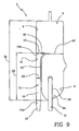
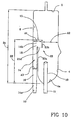
- Figure 10 alternative embodiment has one chamber only: i.e. the first chamber. Notice however that the first chamber of figure 10 could be associated to a second chamber in a way similar to the embodiment of figures 1-6 .
- the first channel comprises a connection portion 17 consecutively connecting the second portion to the first portion and having a progressively increasing flow passage cross section.
- connection portion can be obtained by a wall portion inclined with respect to the direction of longitudinal development of each portion 16 and 18.
- the two consecutive portions 16 and 18 are placed one downstream the other and an aperture in correspondence of the area of connection of the two portions. This aperture, together with the above mentioned orifice 15, serves to put the channel 14 into communication with the chamber and gives a preferential path for fluid coming from the inlet port 10 and not having enough kinetic energy to reach the orifice 15.
- A1 is between 1.5 and 2.5 times A3.
- Figure 9 shows an alternative embodiment where the air separator 1 has one chamber only: i.e. the first chamber. Notice however that the first chamber of the embodiment shown in figure 9 could be associated to a second chamber in a way similar to the embodiment of figures 1-6 .
- the channel 14 presents a second portion 18 where the flow passage cross section increases in a progressive and continuous manner moving towards said second end (i.e. with reference to the attached figures the net area for the fluid passage increases moving closer to the top wall).
- the channel 14 can present a continuously and progressively increasing flow passage cross section from said first to said second end.
- A1 is between 1.5 and 2.5 times the measure of A3.
- the first channel 14 has a longitudinal extension parallel to the lateral wall of the first chamber such that the orifice results to be positioned in a certain position relative to said top and said bottom walls.
- D2/D1 is grater than 0.5 and for instance comprised between 0.55 and 0.7.
- the ratio A1/A2 is greater than 0.25, meaning that the fluid does not abruptly pass from a narrow channel into a large chamber but rather the flow passage cross section area of the first channel in correspondence of the orifice is at least 1 ⁇ 4 (in the shown embodiments around 1/3) the flow passage cross section area of the first chamber in correspondence of the orifice (i.e. the area of the fluid passage in the first chamber measured at the same height of the orifice as shown in figure 9 , see references A1 and A2).
- the ratio A1/A2 as above defined is has also an upper limit in that it is less then 1.00 and preferably less than 0.75, meaning that the orifice area is preferably smaller than the area of the first chamber in correspondence of the same section of the air separator.
- the air separator can also comprise a filter 19 engaged to the bottom wall in correspondence of the outlet port 11 and axially extending into the chamber according to a direction substantially parallel to the first portion of the channel.
- the filter can have a substantially cylindrical or frusto-conical or conical overall shape and meshes designed depending upon the needs.
- the filter extends axially into the chamber from the bottom wall 4 lowermost region 4a and presents an overall axial extension into the first chamber (which is identified as D3 in the attached drawings) sensibly less than D2.
- the filter presents an overall axial extension D3 substantially not grater than 0.70 of D3.
- the axial length of the filter is less then that of the first portion 16 of the first channel 14 so that the filter 19 remains sufficiently distant from the first channel orifice 15.
- the air separator can also comprise a second channel 20 (as for instance in the embodiment of figures 1-6 ) extending parallel to the lateral wall of the second chamber 3 and having a first end 20a, connected to the second inlet port 12, and a second end 20b terminating into the second chamber; the second channel has constant cross section and presents a deflector 21 in correspondence of its second end defining an orifice 22 facing the lateral wall 9 of the second chamber.
- a second channel 20 (as for instance in the embodiment of figures 1-6 ) extending parallel to the lateral wall of the second chamber 3 and having a first end 20a, connected to the second inlet port 12, and a second end 20b terminating into the second chamber; the second channel has constant cross section and presents a deflector 21 in correspondence of its second end defining an orifice 22 facing the lateral wall 9 of the second chamber.
- the orifice 22 faces the lateral wall 9 and extends across an area which is below the horizontal plane where the orifice 15 of the first channel lies (again with reference
- the overall air separator of the shown embodiments has a flattened configuration where said first channel and said first chamber have a substantially square shaped transverse section.
- the separator can be made in rigid and transparent plastic material.
- plastic materials such as PETG, PVC; however, any other suitable material could be of course equivalently used without departing from the scope of the invention which is directed to the geometry of the separator rather then to the specific materials used for the manufacture.
- the following materials could represent alternative choices for the separator manufacturing: Copolyester (e.g. Eastar copolyester PETG from Eastman Chemical Company), Acrylic-based multipolymer compounds (e.g.
- the entire air separator is made can be in one single piece, for instance by injection molding.
- the first channel 14 and the first chamber walls 4,5,6 are in one single plastic piece where the channel 14 presents a lateral wall having a longitudinal portion in common with a portion of the first chamber lateral wall.
- each one of the first and second blood chambers presents a lateral wall formed by a front wall, a rear wall spaced from the front wall, side walls extending between said front and rear walls.
- the first and second chamber are joined in correspondence of one common side wall 25 which extends in correspondence of a central zone of the air separator; the front and rear walls of each chamber are coplanar and cooperate to define the front and rear walls of the entire air separator.
- An intermediate wall 23 extends between the front and rear walls of each blood chamber and laterally delimits the respective channel in cooperation with one of said side walls.
- the intermediate wall 23 associated with the first blood chamber presents a first wall portion 23a parallel to one of the side walls, a second wall portion 23b parallel to the same side wall and a deflecting portion 23c connecting said first and second portion thereby forming said first and second portions 16 and 18 as well as portion 17.
- the wall 23 presents a terminal curved portion defining the second portion 18 of first channel14.
- the intermediate wall 23 is defined by two (or more) wall portions 23a and 23b separated by an aperture 23d.
- the lateral wall of the first chamber can be designed to include pressure transducer means 24.
- the first channel ends immediately below said pressure transducer means.
- the second chamber can have respective pressure transducer means 24.
- the pressure transducer means can include a hole on the air separator wall and a respective diaphragm tightly occluding the hole. The diaphragm is subject to deformation under the action of a pressure difference between the inside and the outside of each respective chamber and transmits a corresponding pressure signal to a tube connected to a pressure sensor inside the dialysis machine (or other treatment machine).
- U.S. Pat. No. 4,666,598 discloses in detail a possible embodiment for the pressure transducer means of the type just described.
- the pressure transducer means could also be different from the above described solution: for instance the diaphragm could be integrally in the obtained in the side wall by a thickness reduction in the wall which defines a movable part integral with the rest of the wall. According to a further alternative pressure could be detected via respective lines bringing the air to corresponding transducers remote from the air separator. Still another alternative provides for pressure sensors directly integrated on the separator wall and directly providing an electric signal function of the pressure inside the separator (piezoelectric sensors could be used). However, the way pressure in the blood chambers is detected is however not relevant for the present invention and any alternative means could equivalently be adopted.
- FIG 11 discloses an extracorporeal blood circuit 60 wherein air separator 1 of the type of figures 1-6 is used.
- the blood circuit 60 comprises an arterial line 70 which has at least one end 71 designed to be connected to a patient and another end 72 designed to be connected with a blood treatment unit, a venous line 73 which has at least one end 74 designed to be connected to a patient and another end 75 designed to be connected with a blood treatment unit.
- the air separator of present invention is associated to the venous and arterial lines as here below described in details.
- the venous line 73 includes a first flexible tube 79 having one end engaged to the inlet port 10 of the first blood chamber 2 and the opposite end 75 where a connector can be present.
- the venous line also includes a second flexible tube 80 having one end engaged to the outlet port 11 of the first blood chamber and the other end, which has already been identified with reference numeral 74, being for connection with a patient (via an access device not shown in the attached drawings).
- the arterial line 70 includes a third flexible tube 81 engaged to the inlet port 12 of the second blood chamber and terminating in correspondence of said end 71.
- the arterial line also includes a fourth flexible tube 82 engaged to the outlet port 13 of the second blood chamber and to one wall of said second blood chamber for forming a loop 83 which is symmetric about a loop axis transverse to the lateral wall of the second chamber.
- the tube 82 connects the outlet port 13 with a rigid channel 84 extending above the chambers 2 and 3 which then leads to a fifth flexible tube 85 terminating in correspondence of said end 72 where a connector can be present.
- the blood circuit could also be provided with one or more infusion lines which can be branched to anyone of tubes 79 and/or 80 and/or 81 and/or 85.
- tubular extensions 86 engaging the tube 82 together with one or more projections 87 are used to lock in operating position the air separator to a treatment machine panel.
- Looped tube 82 fits around the rollers of a peristaltic pump (not shown) carried on the front of the machine and liquid (blood or other liquid) can be pumped into the blood circuit.
- a peristaltic pump not shown
- liquid blood or other liquid
- the described tubing can be made in any plastic material suitable for medical use, such as Single layer tubing made from Plasticized PVC (DEHP, or DEHP-free alternatives as plasticizer); multi-layer tubing including an outer layer of Plasticized PVC (DEHP, or DEHP-free alternatives as plasticizer), or Chlorine-free polymeric materials (e.g. thermoplastic elastomer polyurethanes, SEBS or SEPS-based compounds) and comprising an inner layer of polymeric material obtained from a combination of at least a polyolefin chosen in the group formed by polyethylene or polypropylene and at least one elastomer chosen in the group formed by SEPS or SEBS.
- PEHP Plasticized PVC
- DEHP DEHP-free alternatives as plasticizer
- Chlorine-free polymeric materials e.g. thermoplastic elastomer polyurethanes, SEBS or SEPS-based compounds
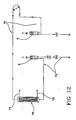
- Figure 12 schematically shows the fluids flow circuit defined by the blood circuit and the air separator of figure 11 when they are connected to a blood treatment unit 76 of a blood treatment machine.
- the blood treatment unit can be for instance formed by a casing housing a semipermeable membrane separating a blood chamber and a treatment fluid chamber.
- the blood chamber of unit 76 is connected with the arterial and venous line ends 72 and 75.
- the treatment fluid chamber is connected in use with an outlet line 77, for the spent treatment liquid, and with an inlet line 78, for the fresh treatment liquid (prepared by the blood treatment machine or coming from appropriate containers. Of course in case of treatments where no fresh liquid is required, then the treatment fluid chamber is only connected with outlet line 77.
- the blood circuit can be connected to corresponding connectors leading to a blood chamber of a dialyzer, of a hemofilter, of a plasmafilter, of an ultrafilter, of an hemodiafilter or of other treatment unit.
- the channel 14 directs the liquid towards the air separator top wall and provides for a uniform speed reduction in the flow as the channel is relatively long as compared to the chamber vertical and relatively wide in correspondence of the orifice. Therefore the liquid leaves the channel in a position which is sufficiently distant from the outlet port; moreover the direction of the flow, the speed reduction and uniform flow allow for a very efficient de-bubbling with no foam creation and minimal perturbations in correspondence of the air-blood interface (see figure 7B ).
- FIG. 7B Significant is the comparison of figures 7A and 7B wherein one can easily see how the air separator of the invention provides for significant reduction in the perturbation and for a more stable liquid level.
- FIGS. 8A and 8B emphasize the improvement offered by the present invention as the entire filter 19 surface is touched by fluid having a certain sufficiently high speed.
- the filter of the prior art chamber of figure 8A presents a top region of fluid stagnation.
Priority Applications (1)
| Application Number | Priority Date | Filing Date | Title |
|---|---|---|---|
| PL11008163T PL2407191T3 (pl) | 2006-10-30 | 2006-10-30 | Zestawy do pozaustrojowej terapii płynowej z zastosowaniem oddzielacza powietrza |
Applications Claiming Priority (2)
| Application Number | Priority Date | Filing Date | Title |
|---|---|---|---|
| PCT/IB2006/003038 WO2008053261A1 (en) | 2006-10-30 | 2006-10-30 | Air separator for extracorporeal fluid treatment sets |
| EP06809137A EP2081620B1 (en) | 2006-10-30 | 2006-10-30 | Air separator for extracorporeal fluid treatment sets |
Related Parent Applications (1)
| Application Number | Title | Priority Date | Filing Date |
|---|---|---|---|
| EP06809137.0 Division | 2006-10-30 |
Publications (2)
| Publication Number | Publication Date |
|---|---|
| EP2407191A1 EP2407191A1 (en) | 2012-01-18 |
| EP2407191B1 true EP2407191B1 (en) | 2012-12-12 |
Family
ID=38191119
Family Applications (2)
| Application Number | Title | Priority Date | Filing Date |
|---|---|---|---|
| EP11008163A Active EP2407191B1 (en) | 2006-10-30 | 2006-10-30 | Air separator extracorporeal fluid treatment sets |
| EP06809137A Active EP2081620B1 (en) | 2006-10-30 | 2006-10-30 | Air separator for extracorporeal fluid treatment sets |
Family Applications After (1)
| Application Number | Title | Priority Date | Filing Date |
|---|---|---|---|
| EP06809137A Active EP2081620B1 (en) | 2006-10-30 | 2006-10-30 | Air separator for extracorporeal fluid treatment sets |
Country Status (10)
| Country | Link |
|---|---|
| US (2) | US8747342B2 (zh) |
| EP (2) | EP2407191B1 (zh) |
| KR (1) | KR101066506B1 (zh) |
| CN (1) | CN101534879B (zh) |
| AT (1) | ATE534418T1 (zh) |
| AU (2) | AU2006350461B2 (zh) |
| CA (2) | CA2753895C (zh) |
| ES (2) | ES2401073T3 (zh) |
| PL (2) | PL2407191T3 (zh) |
| WO (1) | WO2008053261A1 (zh) |
Families Citing this family (24)
| Publication number | Priority date | Publication date | Assignee | Title |
|---|---|---|---|---|
| US7871391B2 (en) * | 2005-10-21 | 2011-01-18 | Fresenius Medical Care Holdings, Inc. | Extracorporeal fluid circuit |
| CA2698408C (en) * | 2007-09-19 | 2015-11-03 | Fresenius Medical Care Holdings, Inc. | Safety vent structure for extracorporeal circuit |
| CA2698409C (en) | 2007-09-19 | 2016-01-12 | Fresenius Medical Care Holdings, Inc. | Dialysis systems and related components |
| US8663463B2 (en) * | 2009-02-18 | 2014-03-04 | Fresenius Medical Care Holdings, Inc. | Extracorporeal fluid circuit and related components |
| EP2229970B1 (en) | 2009-03-16 | 2012-06-06 | F. Hoffmann-La Roche AG | Bubble trap system for an infusion pump device |
| US8753515B2 (en) | 2009-12-05 | 2014-06-17 | Home Dialysis Plus, Ltd. | Dialysis system with ultrafiltration control |
| US9220832B2 (en) | 2010-01-07 | 2015-12-29 | Fresenius Medical Care Holdings, Inc. | Dialysis systems and methods |
| US8500994B2 (en) | 2010-01-07 | 2013-08-06 | Fresenius Medical Care Holdings, Inc. | Dialysis systems and methods |
| US8501009B2 (en) | 2010-06-07 | 2013-08-06 | State Of Oregon Acting By And Through The State Board Of Higher Education On Behalf Of Oregon State University | Fluid purification system |
| US8506684B2 (en) | 2010-12-15 | 2013-08-13 | Fresenius Medical Care Holdings, Inc. | Gas release devices for extracorporeal fluid circuits and related methods |
| US9375524B2 (en) | 2011-06-03 | 2016-06-28 | Fresenius Medical Care Holdings, Inc. | Method and arrangement for venting gases from a container having a powdered concentrate for use in hemodialysis |
| AU2012318561B2 (en) | 2011-10-07 | 2017-04-20 | Outset Medical, Inc. | Heat exchange fluid purification for dialysis system |
| JP6295403B2 (ja) * | 2013-06-19 | 2018-03-20 | Fdk株式会社 | 積層インダクタ |
| US9433721B2 (en) | 2013-06-25 | 2016-09-06 | Fresenius Medical Care Holdings, Inc. | Vial spiking assemblies and related methods |
| US20150314055A1 (en) | 2014-04-29 | 2015-11-05 | Michael Edward HOGARD | Dialysis system and methods |
| JP6062468B2 (ja) * | 2015-03-03 | 2017-01-18 | 日機装株式会社 | エアトラップチャンバ |
| US9974942B2 (en) | 2015-06-19 | 2018-05-22 | Fresenius Medical Care Holdings, Inc. | Non-vented vial drug delivery |
| US9945838B2 (en) | 2015-12-17 | 2018-04-17 | Fresenius Medical Care Holdings, Inc. | Extracorporeal circuit blood chamber having an integrated deaeration device |
| US10625009B2 (en) | 2016-02-17 | 2020-04-21 | Baxter International Inc. | Airtrap, system and method for removing microbubbles from a fluid stream |
| DE102016109340B4 (de) * | 2016-05-20 | 2024-01-04 | Fresenius Medical Care Deutschland Gmbh | Medizinische Kondensatfalle zur medizinischen Verwendung, Verfahren zur Entfeuchtung, Blutbehandlungsvorrichtung, Blutbehandlungseinrichtung |
| JP2019520139A (ja) * | 2016-06-23 | 2019-07-18 | メドトロニック,インコーポレイテッド | 静脈空気捕捉チャンバ |
| GB201612505D0 (en) * | 2016-07-19 | 2016-08-31 | Oxyless Ltd | Flow deflector for dialysis bloodline set |
| ES2908601T3 (es) | 2016-08-19 | 2022-05-03 | Outset Medical Inc | Sistema y métodos de diálisis peritoneal |
| EP3895799A1 (en) * | 2020-04-17 | 2021-10-20 | Sartorius Stedim Biotech GmbH | A fluid processing system |
Family Cites Families (128)
| Publication number | Priority date | Publication date | Assignee | Title |
|---|---|---|---|---|
| DE3100442C1 (de) | 1962-05-08 | 1982-09-30 | Dr. Eduard Fresenius, Chemisch-pharmazeutische Industrie KG, 6380 Bad Homburg | Anschlußstück für Kunststoffkanülen und Venenkatheter |
| US3710942A (en) | 1967-06-02 | 1973-01-16 | Pall Corp | Valve for fluid lines and structures containing the same |
| GB1192986A (en) | 1967-08-31 | 1970-05-28 | Eschmann Bros & Walsh Ltd | Intravenous Valve Assembly |
| US3601152A (en) | 1969-08-15 | 1971-08-24 | Grant F Kenworthy | Unidirectional flow valve |
| US3804113A (en) | 1971-06-21 | 1974-04-16 | Alfa Romeo Spa | Automatic non-return valve |
| US3776937A (en) | 1972-06-23 | 1973-12-04 | Lummus Co | Process for the manufacture of aromatic nitriles |
| US3978857A (en) | 1972-08-14 | 1976-09-07 | American Hospital Supply Corporation | System with filter for administrating parenteral liquids |
| US3889710A (en) | 1972-11-07 | 1975-06-17 | Julien H Brost | Check valve with elastomeric valve element |
| US4084606A (en) | 1974-04-23 | 1978-04-18 | Baxter Travenol Laboratories, Inc. | Fluid transfer device |
| US3878095A (en) * | 1974-05-02 | 1975-04-15 | Advanced Medical Sciences Inc | Dialysis apparatus |
| US3990439A (en) | 1974-12-05 | 1976-11-09 | Esb Incorporated | Protective breathing apparatus and valve therefor |
| US4005710A (en) | 1975-02-12 | 1977-02-01 | Abbott Laboratories | Parenteral apparatus with one-way valve |
| US4031891A (en) | 1975-11-03 | 1977-06-28 | Baxter Travenol Laboratories, Inc. | Air eliminating filter |
| GB1527380A (en) * | 1975-11-05 | 1978-10-04 | Nycotron As | Bubble trap and flowmeter combination |
| JPS52110577A (en) | 1976-03-13 | 1977-09-16 | Konishiroku Photo Ind Co Ltd | Photoconductive material |
| US4436620A (en) * | 1977-05-09 | 1984-03-13 | Baxter Travenol Laboratories, Inc. | Integral hydraulic circuit for hemodialysis apparatus |
| US4141379A (en) | 1977-05-16 | 1979-02-27 | Cutter Laboratories, Inc. | Check valve |
| AU3775578A (en) | 1977-07-08 | 1980-01-10 | Johnson & Johnson | Vented filter assembly |
| US4181146A (en) | 1977-07-21 | 1980-01-01 | Luigi Goglio | Two-way valve closing at balanced pressure condition |
| US4190426A (en) | 1977-11-30 | 1980-02-26 | Baxter Travenol Laboratories, Inc. | Gas separating and venting filter |
| US4349035A (en) | 1978-03-14 | 1982-09-14 | Johnson & Johnson | Blood collection assembly with unidirectional flow valve |
| US4222407A (en) | 1978-09-13 | 1980-09-16 | Baxter Travenol Laboratories, Inc. | One-way flex valve |
| US4263808A (en) | 1979-03-26 | 1981-04-28 | Baxter Travenol Laboratories, Inc. | Noninvasive pressure monitor |
| US4354492A (en) | 1979-04-16 | 1982-10-19 | American Hospital Supply Corporation | Medical administration set with backflow check valve |
| US4286628A (en) | 1979-06-21 | 1981-09-01 | Nypro, Inc. | Control of fluid flow using longitudinally movable disc |
| US4246932A (en) | 1979-10-18 | 1981-01-27 | Burron Medical, Inc. | Multiple additive valve assembly |
| US4344777A (en) * | 1980-01-07 | 1982-08-17 | Siposs George G | Directed flow bubble trap for arterial blood |
| US4310017A (en) | 1980-01-30 | 1982-01-12 | Burron Medical Inc. | Backflow check valve for use with IV administration sets |
| SE423318B (sv) * | 1980-06-27 | 1982-05-03 | Gambro Ab | Memofiltrationssystem |
| SE448518B (sv) | 1981-02-16 | 1987-03-02 | Gambro Dialysatoren | Genomstromningskammare for blod eller liknande omtaliga vetskor |
| US4369812A (en) | 1981-02-18 | 1983-01-25 | Nypro Inc. | Control of fluid flow using precisely positioned disc |
| US4395260A (en) | 1981-06-01 | 1983-07-26 | Sorenson Research Co., Inc. | Drip chamber |
| US4439189A (en) * | 1981-06-18 | 1984-03-27 | Bentley Laboratories, Inc. | Pleural drainage system |
| US4447230A (en) | 1981-08-05 | 1984-05-08 | Quest Medical, Inc. | Intravenous administration set assembly |
| US4715959A (en) * | 1982-08-31 | 1987-12-29 | Cd Medical Inc. | Apparatus and method for controlling ultrafiltration during hemodialysis |
| DE3313421C2 (de) * | 1983-04-13 | 1985-08-08 | Fresenius AG, 6380 Bad Homburg | Einrichtung zum Regeln der Ultrafiltrationsrate bei Vorrichtungen zum extrakorporalen Reinigen von Blut |
| US4535820A (en) | 1984-05-24 | 1985-08-20 | Burron Medical Inc. | Normally closed check valve |
| US4556086A (en) | 1984-09-26 | 1985-12-03 | Burron Medical Inc. | Dual disc low pressure back-check valve |
| DE3444671A1 (de) * | 1984-12-07 | 1986-06-12 | Fresenius AG, 6380 Bad Homburg | Haemodiafiltrationsgeraet |
| US4646781A (en) | 1985-05-07 | 1987-03-03 | Pacesetter Infusion, Ltd. | Diaphragm valve for medication infusion pump |
| US4798090A (en) | 1985-06-25 | 1989-01-17 | Cobe Laboratories, Inc. | Apparatus for use with fluid flow transfer device |
| US4666598A (en) | 1985-06-25 | 1987-05-19 | Cobe Laboratories, Inc. | Apparatus for use with fluid flow transfer device |
| US4770787A (en) * | 1985-06-25 | 1988-09-13 | Cobe Laboratories, Inc. | Method of operating a fluid flow transfer device |
| US4668598A (en) | 1985-07-12 | 1987-05-26 | Gaf Corporation | Multicolor images using an electron beam |
| US4687473A (en) | 1986-02-06 | 1987-08-18 | Burron Medical Inc. | Self-contained secondary solution set |
| US4863452A (en) * | 1986-02-12 | 1989-09-05 | Minntech Corporation | Venous reservoir |
| US4681606A (en) | 1986-02-26 | 1987-07-21 | Cobe Laboratories, Inc. | Drip chamber |
| EP0240590B1 (de) | 1986-04-11 | 1991-08-28 | B. Braun-SSC AG | Injektions-Absperrventil |
| EP0247213A1 (en) | 1986-05-21 | 1987-12-02 | B. Braun-SSC AG | Filter for eliminating air |
| US4712583A (en) | 1986-05-27 | 1987-12-15 | Pacesetter Infusion, Ltd. | Precision passive flat-top valve for medication infusion system |
| US4683916A (en) | 1986-09-25 | 1987-08-04 | Burron Medical Inc. | Normally closed automatic reflux valve |
| US4729401A (en) | 1987-01-29 | 1988-03-08 | Burron Medical Inc. | Aspiration assembly having dual co-axial check valves |
| US5251873B1 (en) | 1992-06-04 | 1995-05-02 | Vernay Laboratories | Medical coupling site. |
| SE465404B (sv) * | 1988-03-03 | 1991-09-09 | Gambro Ab | Dialyssystem |
| DE3837498A1 (de) * | 1988-11-04 | 1990-05-17 | Fresenius Ag | Verfahren und vorrichtung zur ultrafiltration bei der haemodialyse |
| DE3922291C1 (en) | 1989-07-06 | 1990-11-08 | Pfrimmer-Viggo Gmbh & Co Kg, 8520 Erlangen, De | Medical non-return valve - has diaphragm moved against lip seal around valve axis |
| US5025829A (en) | 1990-01-29 | 1991-06-25 | Harmac Medical Products, Inc. | Parenteral check valve |
| US5010925A (en) | 1990-04-09 | 1991-04-30 | Vernay Laboratories, Inc. | Normally closed duckbill valve assembly |
| US5397299A (en) * | 1990-07-20 | 1995-03-14 | Atrium Medical Corporation | Fluid recovery system with improvements molded in body |
| US5201722A (en) | 1990-09-04 | 1993-04-13 | Moorehead Robert H | Two-way outdwelling slit valving of medical liquid flow through a cannula and methods |
| JPH06339527A (ja) | 1990-09-28 | 1994-12-13 | Pall Corp | フローメータ |
| US5064168A (en) | 1991-01-23 | 1991-11-12 | Burron Medical, Inc. | Spool valve with offset outlet |
| US5486286A (en) * | 1991-04-19 | 1996-01-23 | Althin Medical, Inc. | Apparatus for performing a self-test of kidney dialysis membrane |
| US5247434A (en) * | 1991-04-19 | 1993-09-21 | Althin Medical, Inc. | Method and apparatus for kidney dialysis |
| US5326476A (en) * | 1991-04-19 | 1994-07-05 | Althin Medical, Inc. | Method and apparatus for kidney dialysis using machine with programmable memory |
| DE9105229U1 (zh) | 1991-04-27 | 1991-06-13 | B. Braun Melsungen Ag, 3508 Melsungen, De | |
| FR2680975B1 (fr) | 1991-09-10 | 1998-12-31 | Hospal Ind | Rein artificiel muni de moyens pour doser une substance dans le sang. |
| US5698090A (en) | 1991-09-10 | 1997-12-16 | Hospal Industrie | Artificial kidney for adjusting a concentration of substance in blood |
| US5211849B1 (en) * | 1991-10-11 | 1997-05-27 | Childrens Hosp Medical Center | Hemofiltration system and method |
| US6471872B2 (en) * | 1991-10-11 | 2002-10-29 | Children's Hospital Medical Center | Hemofiltration system and method based on monitored patient parameters |
| CA2094102A1 (en) | 1992-04-30 | 1993-10-31 | David S. Utterberg | Blood air trap chamber |
| DE4393316T1 (de) | 1992-07-13 | 1995-05-11 | Pall Corp | Automatisiertes System und Verfahren zur Behandlung eines biologischen Fluids |
| EP0847768B1 (en) * | 1992-10-13 | 2001-09-19 | Baxter International Inc. | Hemodialysis monitoring system for hemodialysis machines |
| US5441636A (en) * | 1993-02-12 | 1995-08-15 | Cobe Laboratories, Inc. | Integrated blood treatment fluid module |
| DE4304949C2 (de) | 1993-02-18 | 1996-07-18 | Filtertek Sa | Rückschlagventil für medizinische Anwendungen der Fluidtechnik |
| DE9310673U1 (de) | 1993-07-14 | 1994-08-18 | Braun Melsungen Ag | Rückschlagventil |
| US5447417A (en) | 1993-08-31 | 1995-09-05 | Valleylab Inc. | Self-adjusting pump head and safety manifold cartridge for a peristaltic pump |
| US5591251A (en) * | 1993-11-29 | 1997-01-07 | Cobe Laboratories, Inc. | Side flow bubble trap apparatus and method |
| US5439451A (en) | 1994-03-22 | 1995-08-08 | B. Braun Medical, Inc. | Capless medical backcheck valve |
| DE4442352C1 (de) | 1994-11-29 | 1995-12-21 | Braun Melsungen Ag | Ventilvorrichtung |
| US5727594A (en) | 1995-02-09 | 1998-03-17 | Choksi; Pradip | Low actuation pressure unidirectional flow valve |
| US5932110A (en) | 1995-02-13 | 1999-08-03 | Aksys, Ltd. | Dialysate conductivity adjustment in a batch dialysate preparation system |
| US5591344A (en) | 1995-02-13 | 1997-01-07 | Aksys, Ltd. | Hot water disinfection of dialysis machines, including the extracorporeal circuit thereof |
| US5788099A (en) | 1995-02-13 | 1998-08-04 | Akysys, Ltd. | Vessel for containing batch quantities of dialysate or other physiologic solution chemicals |
| EP0830158B1 (en) * | 1995-06-07 | 2006-09-06 | Gambro, Inc., | Extracorporeal blood processing apparatus and method for operating such an apparatus |
| US5623969A (en) | 1995-06-07 | 1997-04-29 | B. Braun Medical Inc. | Normally closed aspiration valve |
| US5769811A (en) | 1995-10-31 | 1998-06-23 | Haemonetics Corporation | Blood-processing machine system |
| DE19545421C2 (de) | 1995-12-06 | 2001-05-10 | Filtertek Bv | Rückschlagventil, insbesondere für die Medizintechnik |
| US5827429A (en) | 1996-01-18 | 1998-10-27 | Filtertek Inc. | Intravenous filter device |
| US5634905A (en) | 1996-02-14 | 1997-06-03 | W. L. Gore & Associates, Inc. | Apparatus for the prevention of retrograde movement of fluids during the use of air eliminating filters in intravenous therapy |
| US6083187A (en) * | 1996-09-09 | 2000-07-04 | Kaneka Corporation | Method and apparatus for treating blood |
| DE59611439D1 (de) | 1996-12-17 | 2007-09-06 | Filtertek Bv | Rückschlagventil, insbesondere für die Medizintechnik |
| US6979309B2 (en) * | 1997-02-14 | 2005-12-27 | Nxstage Medical Inc. | Systems and methods for performing blood processing and/or fluid exchange procedures |
| JP4416368B2 (ja) * | 1997-02-14 | 2010-02-17 | ネクステージ メディカル インコーポレイテッド | カートリッジ内に配置された体外流体流パネルを使用する流体処理装置及び方法 |
| DE29800107U1 (de) | 1998-01-07 | 1998-03-05 | Braun Melsungen Ag | Schlauchkupplung für ein medizinisches Überleitungssystem |
| US6582385B2 (en) * | 1998-02-19 | 2003-06-24 | Nstage Medical, Inc. | Hemofiltration system including ultrafiltrate purification and re-infusion system |
| US6287516B1 (en) * | 1998-07-10 | 2001-09-11 | Immunocept, L.L.C. | Hemofiltration systems, methods, and devices used to treat inflammatory mediator related disease |
| CA2338952C (en) * | 1998-07-31 | 2007-04-03 | Nephros, Inc. | Method for efficient hemodiafiltration |
| US6468427B1 (en) * | 1998-09-29 | 2002-10-22 | Gambro, Inc. | Fluid filter for use in extracorporeal blood processing |
| JP4436569B2 (ja) * | 1998-10-30 | 2010-03-24 | ネフロス・インコーポレーテッド | 浸透圧差による透過型濾過システム |
| DE60031966T2 (de) * | 1999-04-23 | 2007-09-13 | Renamed Biologics, Inc. | Extrakorporaler kreislauf |
| AU766427B2 (en) * | 1999-04-30 | 2003-10-16 | Children's Hospital Medical Center | Hemofiltration system and method baded on monitored patient parameters, supervisory control of hemofiltration, and adaptive control of pumps for hemofiltration |
| US6406631B1 (en) * | 1999-07-30 | 2002-06-18 | Nephros, Inc. | Two stage diafiltration method and apparatus |
| IT1311245B1 (it) | 1999-10-22 | 2002-03-04 | Borla Ind | Valvola anti-sifone per linee medicali di infusione e simili. |
| ES2191604T3 (es) | 1999-11-12 | 2003-09-16 | Borla Ind | Valvula de retencion para lineas de infusion de uso medico y similares. |
| IT1311347B1 (it) | 1999-11-12 | 2002-03-12 | Borla Ind | Valvola di ritegno per linee medicali di infusione e simili. |
| IT1311348B1 (it) | 1999-11-12 | 2002-03-12 | Borla Ind | Valvola di ritegno per linee medicali di infusione e simili. |
| DE60127657T8 (de) * | 2000-01-11 | 2008-04-17 | Nephros, Inc. | Blutreinigungssystem |
| US7067060B2 (en) * | 2000-01-11 | 2006-06-27 | Nephros, Inc. | Ionic enhanced dialysis/diafiltration system |
| US6736972B1 (en) * | 2000-03-24 | 2004-05-18 | Immunocept, L.L.C. | Method and system for providing therapeutic agents with hemofiltration for reducing inflammatory mediator related diseases |
| US7291122B2 (en) * | 2000-03-24 | 2007-11-06 | Immunocept, L.L.C. | Hemofiltration methods for treatment of diseases in a mammal |
| WO2001095955A1 (fr) * | 2000-06-15 | 2001-12-20 | Jms Co., Ltd. | Dialyseur automatique et procede de dialyse |
| JP4077722B2 (ja) * | 2000-10-12 | 2008-04-23 | リナル・ソリューションズ・インコーポレーテッド | 体外流体処理時における体液の流れを制御する装置及び方法 |
| ITTO20010583A1 (it) * | 2001-06-15 | 2002-12-15 | Gambro Dasco Spa | Circuito di circolazione del sangue per una macchina di dialisi e relativa macchina di dialisi. |
| US6649063B2 (en) * | 2001-07-12 | 2003-11-18 | Nxstage Medical, Inc. | Method for performing renal replacement therapy including producing sterile replacement fluid in a renal replacement therapy unit |
| SE525132C2 (sv) * | 2001-11-23 | 2004-12-07 | Gambro Lundia Ab | Metod vid manövrering av dialysanordning |
| EP1314442A1 (fr) * | 2001-11-26 | 2003-05-28 | Infomed S.A. | Dispositif d'épuration intra- et extracorporelle |
| DE10159620C1 (de) * | 2001-12-05 | 2003-08-14 | Fresenius Medical Care De Gmbh | Verfahren und Einrichtung zur Überwachung der Zufuhr von Substitutionsflüssigkeit während einer extrakorporalen Blutbehandlung |
| ITMI20012829A1 (it) * | 2001-12-28 | 2003-06-28 | Gambro Dasco Spa | Apparecchiatura e metodo di controllo in un circuito extracorporeo disangue |
| DE10224750A1 (de) * | 2002-06-04 | 2003-12-24 | Fresenius Medical Care De Gmbh | Vorrichtung zur Behandlung einer medizinischen Flüssigkeit |
| US6824112B2 (en) * | 2002-10-01 | 2004-11-30 | Hllb, Llc | Baby bottle holder |
| US7264607B2 (en) * | 2003-03-21 | 2007-09-04 | Gambro Lundia Ab | Circuit for extracorporeal blood circulation |
| US20040219059A1 (en) * | 2003-05-03 | 2004-11-04 | Novosci Corp. | Heart bypass system incorporating minimized extracorporeal blood circulation system and related method of use |
| US7559911B2 (en) | 2003-09-05 | 2009-07-14 | Gambro Lundia Ab | Blood chamber for extracorporeal blood circuits and a process for manufacturing the blood chamber |
| US8029454B2 (en) * | 2003-11-05 | 2011-10-04 | Baxter International Inc. | High convection home hemodialysis/hemofiltration and sorbent system |
| US7744553B2 (en) * | 2003-12-16 | 2010-06-29 | Baxter International Inc. | Medical fluid therapy flow control systems and methods |
| CN1327913C (zh) | 2004-04-23 | 2007-07-25 | 暨南大学 | 一种用于血液透析设备中透析液回来的配液供液方法及其装置 |
| WO2008053262A1 (en) * | 2006-10-30 | 2008-05-08 | Gambro Lundia Ab | Medical fluid circuit unit |
-
2006
- 2006-10-30 US US12/447,641 patent/US8747342B2/en active Active
- 2006-10-30 AT AT06809137T patent/ATE534418T1/de active
- 2006-10-30 AU AU2006350461A patent/AU2006350461B2/en active Active
- 2006-10-30 EP EP11008163A patent/EP2407191B1/en active Active
- 2006-10-30 PL PL11008163T patent/PL2407191T3/pl unknown
- 2006-10-30 EP EP06809137A patent/EP2081620B1/en active Active
- 2006-10-30 ES ES11008163T patent/ES2401073T3/es active Active
- 2006-10-30 CA CA2753895A patent/CA2753895C/en active Active
- 2006-10-30 ES ES06809137T patent/ES2375210T3/es active Active
- 2006-10-30 WO PCT/IB2006/003038 patent/WO2008053261A1/en active Application Filing
- 2006-10-30 KR KR1020097010258A patent/KR101066506B1/ko active IP Right Grant
- 2006-10-30 PL PL06809137T patent/PL2081620T3/pl unknown
- 2006-10-30 CN CN2006800562638A patent/CN101534879B/zh active Active
- 2006-10-30 CA CA2670156A patent/CA2670156C/en active Active
-
2011
- 2011-02-09 AU AU2011200545A patent/AU2011200545B2/en active Active
-
2014
- 2014-04-28 US US14/263,544 patent/US10010665B2/en active Active
Also Published As
| Publication number | Publication date |
|---|---|
| CA2753895A1 (en) | 2008-05-08 |
| CA2670156A1 (en) | 2008-05-08 |
| EP2081620A1 (en) | 2009-07-29 |
| US10010665B2 (en) | 2018-07-03 |
| CA2670156C (en) | 2011-12-20 |
| PL2407191T3 (pl) | 2013-05-31 |
| ES2401073T3 (es) | 2013-04-16 |
| PL2081620T3 (pl) | 2012-04-30 |
| US20140230657A1 (en) | 2014-08-21 |
| ES2375210T3 (es) | 2012-02-27 |
| AU2011200545B2 (en) | 2012-04-26 |
| CN101534879A (zh) | 2009-09-16 |
| KR20090086997A (ko) | 2009-08-14 |
| US20100292627A1 (en) | 2010-11-18 |
| CA2753895C (en) | 2013-12-10 |
| EP2081620B1 (en) | 2011-11-23 |
| US8747342B2 (en) | 2014-06-10 |
| AU2011200545A1 (en) | 2011-03-03 |
| AU2006350461B2 (en) | 2010-11-11 |
| AU2006350461A1 (en) | 2008-05-08 |
| KR101066506B1 (ko) | 2011-09-21 |
| EP2407191A1 (en) | 2012-01-18 |
| ATE534418T1 (de) | 2011-12-15 |
| CN101534879B (zh) | 2012-07-25 |
| WO2008053261A1 (en) | 2008-05-08 |
Similar Documents
| Publication | Publication Date | Title |
|---|---|---|
| EP2407191B1 (en) | Air separator extracorporeal fluid treatment sets | |
| EP1680156B1 (en) | Fluid distribution module and extracorporeal blood circuit including such a module | |
| CA2544612C (en) | Degassing device and end-cap assembly for a filter including such a degassing device | |
| CA2671077C (en) | A blood transfer chamber | |
| EP0800838A2 (en) | Hemodialysis apparatus with upright U-shaped pump tubing | |
| WO1999058175A1 (en) | Blood set and chamber | |
| JP6728726B2 (ja) | フィルタ内蔵型人工肺 | |
| EP3782672B1 (en) | Pressure detector | |
| JP5922777B2 (ja) | 血液処理フィルター、血液回路、及び血液処理方法 | |
| CN102698332B (zh) | 用于体外流体处理套件的空气分离器 | |
| JP5390578B2 (ja) | エアトラップチャンバ | |
| JPH06327769A (ja) | 血漿処理装置 | |
| JP2006158456A (ja) | 血液浄化装置 | |
| JPH0847622A (ja) | 透析装置 |
Legal Events
| Date | Code | Title | Description |
|---|---|---|---|
| AC | Divisional application: reference to earlier application |
Ref document number: 2081620 Country of ref document: EP Kind code of ref document: P |
|
| AK | Designated contracting states |
Kind code of ref document: A1 Designated state(s): AT BE BG CH CY CZ DE DK EE ES FI FR GB GR HU IE IS IT LI LT LU LV MC NL PL PT RO SE SI SK TR |
|
| PUAI | Public reference made under article 153(3) epc to a published international application that has entered the european phase |
Free format text: ORIGINAL CODE: 0009012 |
|
| 17P | Request for examination filed |
Effective date: 20120116 |
|
| RIC1 | Information provided on ipc code assigned before grant |
Ipc: A61M 1/36 20060101AFI20120809BHEP |
|
| GRAP | Despatch of communication of intention to grant a patent |
Free format text: ORIGINAL CODE: EPIDOSNIGR1 |
|
| GRAS | Grant fee paid |
Free format text: ORIGINAL CODE: EPIDOSNIGR3 |
|
| GRAA | (expected) grant |
Free format text: ORIGINAL CODE: 0009210 |
|
| AC | Divisional application: reference to earlier application |
Ref document number: 2081620 Country of ref document: EP Kind code of ref document: P |
|
| AK | Designated contracting states |
Kind code of ref document: B1 Designated state(s): AT BE BG CH CY CZ DE DK EE ES FI FR GB GR HU IE IS IT LI LT LU LV MC NL PL PT RO SE SI SK TR |
|
| REG | Reference to a national code |
Ref country code: GB Ref legal event code: FG4D |
|
| REG | Reference to a national code |
Ref country code: CH Ref legal event code: EP |
|
| REG | Reference to a national code |
Ref country code: AT Ref legal event code: REF Ref document number: 588033 Country of ref document: AT Kind code of ref document: T Effective date: 20121215 |
|
| REG | Reference to a national code |
Ref country code: IE Ref legal event code: FG4D |
|
| REG | Reference to a national code |
Ref country code: DE Ref legal event code: R096 Ref document number: 602006033650 Country of ref document: DE Effective date: 20130207 |
|
| REG | Reference to a national code |
Ref country code: ES Ref legal event code: FG2A Ref document number: 2401073 Country of ref document: ES Kind code of ref document: T3 Effective date: 20130416 |
|
| PG25 | Lapsed in a contracting state [announced via postgrant information from national office to epo] |
Ref country code: FI Free format text: LAPSE BECAUSE OF FAILURE TO SUBMIT A TRANSLATION OF THE DESCRIPTION OR TO PAY THE FEE WITHIN THE PRESCRIBED TIME-LIMIT Effective date: 20121212 Ref country code: LT Free format text: LAPSE BECAUSE OF FAILURE TO SUBMIT A TRANSLATION OF THE DESCRIPTION OR TO PAY THE FEE WITHIN THE PRESCRIBED TIME-LIMIT Effective date: 20121212 Ref country code: SE Free format text: LAPSE BECAUSE OF FAILURE TO SUBMIT A TRANSLATION OF THE DESCRIPTION OR TO PAY THE FEE WITHIN THE PRESCRIBED TIME-LIMIT Effective date: 20121212 |
|
| REG | Reference to a national code |
Ref country code: NL Ref legal event code: VDEP Effective date: 20121212 |
|
| REG | Reference to a national code |
Ref country code: AT Ref legal event code: MK05 Ref document number: 588033 Country of ref document: AT Kind code of ref document: T Effective date: 20121212 |
|
| REG | Reference to a national code |
Ref country code: LT Ref legal event code: MG4D |
|
| PG25 | Lapsed in a contracting state [announced via postgrant information from national office to epo] |
Ref country code: SI Free format text: LAPSE BECAUSE OF FAILURE TO SUBMIT A TRANSLATION OF THE DESCRIPTION OR TO PAY THE FEE WITHIN THE PRESCRIBED TIME-LIMIT Effective date: 20121212 Ref country code: LV Free format text: LAPSE BECAUSE OF FAILURE TO SUBMIT A TRANSLATION OF THE DESCRIPTION OR TO PAY THE FEE WITHIN THE PRESCRIBED TIME-LIMIT Effective date: 20121212 Ref country code: GR Free format text: LAPSE BECAUSE OF FAILURE TO SUBMIT A TRANSLATION OF THE DESCRIPTION OR TO PAY THE FEE WITHIN THE PRESCRIBED TIME-LIMIT Effective date: 20130313 |
|
| REG | Reference to a national code |
Ref country code: PL Ref legal event code: T3 |
|
| PG25 | Lapsed in a contracting state [announced via postgrant information from national office to epo] |
Ref country code: BG Free format text: LAPSE BECAUSE OF FAILURE TO SUBMIT A TRANSLATION OF THE DESCRIPTION OR TO PAY THE FEE WITHIN THE PRESCRIBED TIME-LIMIT Effective date: 20130312 Ref country code: AT Free format text: LAPSE BECAUSE OF FAILURE TO SUBMIT A TRANSLATION OF THE DESCRIPTION OR TO PAY THE FEE WITHIN THE PRESCRIBED TIME-LIMIT Effective date: 20121212 Ref country code: CZ Free format text: LAPSE BECAUSE OF FAILURE TO SUBMIT A TRANSLATION OF THE DESCRIPTION OR TO PAY THE FEE WITHIN THE PRESCRIBED TIME-LIMIT Effective date: 20121212 Ref country code: BE Free format text: LAPSE BECAUSE OF FAILURE TO SUBMIT A TRANSLATION OF THE DESCRIPTION OR TO PAY THE FEE WITHIN THE PRESCRIBED TIME-LIMIT Effective date: 20121212 Ref country code: SK Free format text: LAPSE BECAUSE OF FAILURE TO SUBMIT A TRANSLATION OF THE DESCRIPTION OR TO PAY THE FEE WITHIN THE PRESCRIBED TIME-LIMIT Effective date: 20121212 Ref country code: IS Free format text: LAPSE BECAUSE OF FAILURE TO SUBMIT A TRANSLATION OF THE DESCRIPTION OR TO PAY THE FEE WITHIN THE PRESCRIBED TIME-LIMIT Effective date: 20130412 Ref country code: EE Free format text: LAPSE BECAUSE OF FAILURE TO SUBMIT A TRANSLATION OF THE DESCRIPTION OR TO PAY THE FEE WITHIN THE PRESCRIBED TIME-LIMIT Effective date: 20121212 |
|
| PG25 | Lapsed in a contracting state [announced via postgrant information from national office to epo] |
Ref country code: NL Free format text: LAPSE BECAUSE OF FAILURE TO SUBMIT A TRANSLATION OF THE DESCRIPTION OR TO PAY THE FEE WITHIN THE PRESCRIBED TIME-LIMIT Effective date: 20121212 Ref country code: PT Free format text: LAPSE BECAUSE OF FAILURE TO SUBMIT A TRANSLATION OF THE DESCRIPTION OR TO PAY THE FEE WITHIN THE PRESCRIBED TIME-LIMIT Effective date: 20130412 Ref country code: RO Free format text: LAPSE BECAUSE OF FAILURE TO SUBMIT A TRANSLATION OF THE DESCRIPTION OR TO PAY THE FEE WITHIN THE PRESCRIBED TIME-LIMIT Effective date: 20121212 |
|
| PLBE | No opposition filed within time limit |
Free format text: ORIGINAL CODE: 0009261 |
|
| STAA | Information on the status of an ep patent application or granted ep patent |
Free format text: STATUS: NO OPPOSITION FILED WITHIN TIME LIMIT |
|
| PG25 | Lapsed in a contracting state [announced via postgrant information from national office to epo] |
Ref country code: DK Free format text: LAPSE BECAUSE OF FAILURE TO SUBMIT A TRANSLATION OF THE DESCRIPTION OR TO PAY THE FEE WITHIN THE PRESCRIBED TIME-LIMIT Effective date: 20121212 |
|
| 26N | No opposition filed |
Effective date: 20130913 |
|
| PG25 | Lapsed in a contracting state [announced via postgrant information from national office to epo] |
Ref country code: CY Free format text: LAPSE BECAUSE OF FAILURE TO SUBMIT A TRANSLATION OF THE DESCRIPTION OR TO PAY THE FEE WITHIN THE PRESCRIBED TIME-LIMIT Effective date: 20121212 |
|
| REG | Reference to a national code |
Ref country code: DE Ref legal event code: R097 Ref document number: 602006033650 Country of ref document: DE Effective date: 20130913 |
|
| PG25 | Lapsed in a contracting state [announced via postgrant information from national office to epo] |
Ref country code: MC Free format text: LAPSE BECAUSE OF FAILURE TO SUBMIT A TRANSLATION OF THE DESCRIPTION OR TO PAY THE FEE WITHIN THE PRESCRIBED TIME-LIMIT Effective date: 20121212 |
|
| REG | Reference to a national code |
Ref country code: CH Ref legal event code: PL |
|
| REG | Reference to a national code |
Ref country code: IE Ref legal event code: MM4A |
|
| PG25 | Lapsed in a contracting state [announced via postgrant information from national office to epo] |
Ref country code: CH Free format text: LAPSE BECAUSE OF NON-PAYMENT OF DUE FEES Effective date: 20131031 Ref country code: LI Free format text: LAPSE BECAUSE OF NON-PAYMENT OF DUE FEES Effective date: 20131031 |
|
| PG25 | Lapsed in a contracting state [announced via postgrant information from national office to epo] |
Ref country code: IE Free format text: LAPSE BECAUSE OF NON-PAYMENT OF DUE FEES Effective date: 20131030 |
|
| PG25 | Lapsed in a contracting state [announced via postgrant information from national office to epo] |
Ref country code: LU Free format text: LAPSE BECAUSE OF NON-PAYMENT OF DUE FEES Effective date: 20131030 Ref country code: HU Free format text: LAPSE BECAUSE OF FAILURE TO SUBMIT A TRANSLATION OF THE DESCRIPTION OR TO PAY THE FEE WITHIN THE PRESCRIBED TIME-LIMIT; INVALID AB INITIO Effective date: 20061030 |
|
| REG | Reference to a national code |
Ref country code: FR Ref legal event code: PLFP Year of fee payment: 11 |
|
| REG | Reference to a national code |
Ref country code: FR Ref legal event code: PLFP Year of fee payment: 12 |
|
| REG | Reference to a national code |
Ref country code: FR Ref legal event code: PLFP Year of fee payment: 13 |
|
| PGFP | Annual fee paid to national office [announced via postgrant information from national office to epo] |
Ref country code: IT Payment date: 20230920 Year of fee payment: 18 Ref country code: GB Payment date: 20230920 Year of fee payment: 18 |
|
| PGFP | Annual fee paid to national office [announced via postgrant information from national office to epo] |
Ref country code: PL Payment date: 20230920 Year of fee payment: 18 Ref country code: FR Payment date: 20230920 Year of fee payment: 18 |
|
| PGFP | Annual fee paid to national office [announced via postgrant information from national office to epo] |
Ref country code: ES Payment date: 20231102 Year of fee payment: 18 |
|
| PGFP | Annual fee paid to national office [announced via postgrant information from national office to epo] |
Ref country code: TR Payment date: 20231002 Year of fee payment: 18 Ref country code: DE Payment date: 20230920 Year of fee payment: 18 |