EP2405090A2 - Scharnier mit Torsions-Spiral-Feder, deren Spannung einstellbar ist - Google Patents
Scharnier mit Torsions-Spiral-Feder, deren Spannung einstellbar ist Download PDFInfo
- Publication number
- EP2405090A2 EP2405090A2 EP11003964A EP11003964A EP2405090A2 EP 2405090 A2 EP2405090 A2 EP 2405090A2 EP 11003964 A EP11003964 A EP 11003964A EP 11003964 A EP11003964 A EP 11003964A EP 2405090 A2 EP2405090 A2 EP 2405090A2
- Authority
- EP
- European Patent Office
- Prior art keywords
- hinge
- worm wheel
- axis
- hinge axis
- worm
- Prior art date
- Legal status (The legal status is an assumption and is not a legal conclusion. Google has not performed a legal analysis and makes no representation as to the accuracy of the status listed.)
- Granted
Links
Images


Classifications
-
- E—FIXED CONSTRUCTIONS
- E05—LOCKS; KEYS; WINDOW OR DOOR FITTINGS; SAFES
- E05F—DEVICES FOR MOVING WINGS INTO OPEN OR CLOSED POSITION; CHECKS FOR WINGS; WING FITTINGS NOT OTHERWISE PROVIDED FOR, CONCERNED WITH THE FUNCTIONING OF THE WING
- E05F1/00—Closers or openers for wings, not otherwise provided for in this subclass
- E05F1/08—Closers or openers for wings, not otherwise provided for in this subclass spring-actuated, e.g. for horizontally sliding wings
- E05F1/10—Closers or openers for wings, not otherwise provided for in this subclass spring-actuated, e.g. for horizontally sliding wings for swinging wings, e.g. counterbalance
- E05F1/12—Mechanisms in the shape of hinges or pivots, operated by springs
- E05F1/1207—Mechanisms in the shape of hinges or pivots, operated by springs with a coil spring parallel with the pivot axis
- E05F1/1215—Mechanisms in the shape of hinges or pivots, operated by springs with a coil spring parallel with the pivot axis with a canted-coil torsion spring
-
- E—FIXED CONSTRUCTIONS
- E05—LOCKS; KEYS; WINDOW OR DOOR FITTINGS; SAFES
- E05D—HINGES OR SUSPENSION DEVICES FOR DOORS, WINDOWS OR WINGS
- E05D3/00—Hinges with pins
- E05D3/02—Hinges with pins with one pin
- E05D2003/025—Hinges with pins with one pin having three knuckles
- E05D2003/027—Hinges with pins with one pin having three knuckles the end knuckles being mutually connected
-
- E—FIXED CONSTRUCTIONS
- E05—LOCKS; KEYS; WINDOW OR DOOR FITTINGS; SAFES
- E05D—HINGES OR SUSPENSION DEVICES FOR DOORS, WINDOWS OR WINGS
- E05D5/00—Construction of single parts, e.g. the parts for attachment
- E05D5/10—Pins, sockets or sleeves; Removable pins
- E05D2005/102—Pins
-
- E—FIXED CONSTRUCTIONS
- E05—LOCKS; KEYS; WINDOW OR DOOR FITTINGS; SAFES
- E05D—HINGES OR SUSPENSION DEVICES FOR DOORS, WINDOWS OR WINGS
- E05D5/00—Construction of single parts, e.g. the parts for attachment
- E05D5/10—Pins, sockets or sleeves; Removable pins
-
- E—FIXED CONSTRUCTIONS
- E05—LOCKS; KEYS; WINDOW OR DOOR FITTINGS; SAFES
- E05Y—INDEXING SCHEME ASSOCIATED WITH SUBCLASSES E05D AND E05F, RELATING TO CONSTRUCTION ELEMENTS, ELECTRIC CONTROL, POWER SUPPLY, POWER SIGNAL OR TRANSMISSION, USER INTERFACES, MOUNTING OR COUPLING, DETAILS, ACCESSORIES, AUXILIARY OPERATIONS NOT OTHERWISE PROVIDED FOR, APPLICATION THEREOF
- E05Y2201/00—Constructional elements; Accessories therefor
- E05Y2201/20—Brakes; Disengaging means; Holders; Stops; Valves; Accessories therefor
- E05Y2201/224—Stops
-
- E—FIXED CONSTRUCTIONS
- E05—LOCKS; KEYS; WINDOW OR DOOR FITTINGS; SAFES
- E05Y—INDEXING SCHEME ASSOCIATED WITH SUBCLASSES E05D AND E05F, RELATING TO CONSTRUCTION ELEMENTS, ELECTRIC CONTROL, POWER SUPPLY, POWER SIGNAL OR TRANSMISSION, USER INTERFACES, MOUNTING OR COUPLING, DETAILS, ACCESSORIES, AUXILIARY OPERATIONS NOT OTHERWISE PROVIDED FOR, APPLICATION THEREOF
- E05Y2201/00—Constructional elements; Accessories therefor
- E05Y2201/40—Motors; Magnets; Springs; Weights; Accessories therefor
- E05Y2201/499—Spring tensioners; Tension sensors
-
- E—FIXED CONSTRUCTIONS
- E05—LOCKS; KEYS; WINDOW OR DOOR FITTINGS; SAFES
- E05Y—INDEXING SCHEME ASSOCIATED WITH SUBCLASSES E05D AND E05F, RELATING TO CONSTRUCTION ELEMENTS, ELECTRIC CONTROL, POWER SUPPLY, POWER SIGNAL OR TRANSMISSION, USER INTERFACES, MOUNTING OR COUPLING, DETAILS, ACCESSORIES, AUXILIARY OPERATIONS NOT OTHERWISE PROVIDED FOR, APPLICATION THEREOF
- E05Y2201/00—Constructional elements; Accessories therefor
- E05Y2201/60—Suspension or transmission members; Accessories therefor
- E05Y2201/622—Suspension or transmission members elements
- E05Y2201/696—Screw mechanisms
- E05Y2201/702—Spindles; Worms
-
- E—FIXED CONSTRUCTIONS
- E05—LOCKS; KEYS; WINDOW OR DOOR FITTINGS; SAFES
- E05Y—INDEXING SCHEME ASSOCIATED WITH SUBCLASSES E05D AND E05F, RELATING TO CONSTRUCTION ELEMENTS, ELECTRIC CONTROL, POWER SUPPLY, POWER SIGNAL OR TRANSMISSION, USER INTERFACES, MOUNTING OR COUPLING, DETAILS, ACCESSORIES, AUXILIARY OPERATIONS NOT OTHERWISE PROVIDED FOR, APPLICATION THEREOF
- E05Y2600/00—Mounting or coupling arrangements for elements provided for in this subclass
- E05Y2600/10—Adjustable
- E05Y2600/20—Adjustable with specific transmission movement
-
- E—FIXED CONSTRUCTIONS
- E05—LOCKS; KEYS; WINDOW OR DOOR FITTINGS; SAFES
- E05Y—INDEXING SCHEME ASSOCIATED WITH SUBCLASSES E05D AND E05F, RELATING TO CONSTRUCTION ELEMENTS, ELECTRIC CONTROL, POWER SUPPLY, POWER SIGNAL OR TRANSMISSION, USER INTERFACES, MOUNTING OR COUPLING, DETAILS, ACCESSORIES, AUXILIARY OPERATIONS NOT OTHERWISE PROVIDED FOR, APPLICATION THEREOF
- E05Y2800/00—Details, accessories and auxiliary operations not otherwise provided for
- E05Y2800/26—Form or shape
- E05Y2800/28—Form or shape tubular, annular
-
- E—FIXED CONSTRUCTIONS
- E05—LOCKS; KEYS; WINDOW OR DOOR FITTINGS; SAFES
- E05Y—INDEXING SCHEME ASSOCIATED WITH SUBCLASSES E05D AND E05F, RELATING TO CONSTRUCTION ELEMENTS, ELECTRIC CONTROL, POWER SUPPLY, POWER SIGNAL OR TRANSMISSION, USER INTERFACES, MOUNTING OR COUPLING, DETAILS, ACCESSORIES, AUXILIARY OPERATIONS NOT OTHERWISE PROVIDED FOR, APPLICATION THEREOF
- E05Y2900/00—Application of doors, windows, wings or fittings thereof
- E05Y2900/50—Application of doors, windows, wings or fittings thereof for vehicles
- E05Y2900/502—Application of doors, windows, wings or fittings thereof for vehicles for aircraft or spacecraft
Definitions
- the invention relates to a hinge with torsion spiral spring whose tension is adjustable.
- the spring tension determines in particular provided with such hinged flaps of luggage boxes in aircraft, the automatic spring-biased opening of the flap.
- a possibility should be provided for reducing the tension of the torsion spring, e.g. to be set by simple operation of a setting element.
- the worm gear according to the invention known per se consists of a helical so-called worm (shaft), which rotates during rotation a gear (worm wheel) engaging in this.
- the axes of the worm and the worm wheel are offset by 90 degrees.
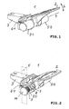
- FIG.1 shows
- FIG. 1 an isometric view of the hinge 1 according to the invention with a view of the hinged about an imaginary mathematical axis 4 in the direction S hinged sheet 2 and on the fixed hinge sheet 3.
- the fixed hinge leaf 3 is rigid with the Axle bearing body of the journal bearing 5-1, 5-2 connected to a (not visible in this view) hinge axis (see FIG.2 . FIG.3 ). This has a hollow cylinder-like shape. Both hinge leaves 2,3 this hinge axis is common.
- a control element 6-1 is arranged for a (not visible in this view) worm gear.
- the worm gear is used to adjust the voltage of a arranged in the hinge axis torsion coil spring.
- FIG.2 shows
- FIG.1 an isometric view of the hinge 1 according to the invention FIG.1 with a broken axle bearing 5-1 facing the hinge axis 7, on the torsion coil spring 8 and on the worm wheel 9 of the worm gear.
- FIG. 3 shows
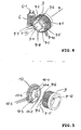
- FIG. 4 shows
- the worm gear consists of the worm wheel 9 and the worm 6.
- the worm wheel 9 is as well as off FIG. 2 and FIG. 8th seen in the axle bearing 5-1 rotatably arranged about the mathematical axis 4 of the hinge axis 7.
- the worm wheel 9 is fixedly connected to the second 8-2 of both ends of the torsion coil spring 8; that is, this end 8-2 rotates with the worm wheel 9 when this 9 is adjusted via the worm 6.
- the screw 6 is as well FIG.2 emerges in the fixed axle bearing body of the axle bearing 5-1 arranged. It is stored at both ends. It engages in the teeth 9-10 of the worm wheel 9 and can be adjusted by the adjusting element 6-1.
- the adjusting element 6-1 can be provided, for example, with a slot (not shown) for a screwdriver operation.
- An adjustment (rotation) of the worm 6 causes a corresponding rotation of the Scheckenrades 9. This allows the tension of the torsion coil spring 8 can be adjusted.
- FIG. 4 and FIG shows, by which constructive measures on the opposite sides of the rotatable worm wheel 9 and the closure element 10th the limitation of the range of rotation is achieved.
- FIG. 5 shows an isometric view of the worm wheel 9 and the closure element 10 for the axle bearing 5-1.
- limiting elements 9-6, 9-7 are arranged, which correspond to the limited rotation range corresponding circular sector 9-3 on the side 9-11 with respect to the axis 4th delimit.
- a stop element 10-1 is arranged on the this side 9-11 opposite side 10-6 of the closure element 10.
- the limited rotation range corresponding circular sectors 9-2, 9-3, 9-4, 9th -1 defined. Of the four circular sectors, two each face each other.
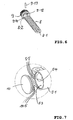
- FIG.6 shows
- FIG.7 shows
- FIG. 7 an isometric view of the worm wheel 9 and the closure element 10 for the axle bearing 5-1.
- the axle box 5-1 ( FIG. 7 ) is a through hole 5-3, through the outer opening 5-4 in the assembly of the hinge, the hinge axis 7 with the torsion coil spring 8 and the worm wheel 9 are introduced.
- This opening 5-4 is closed with the closure element 10.
- nose-like elements 10-5 are arranged concentrically.
- corresponding recesses 5-5 are provided for insertion of these nose-like elements 10-5.
- the insertion position of the closure element 10 is selectable.
- FIG.8 shows
- the worm 6 is arranged in the axle bearing body of the axle bearing 5-1.
- the axle bearing body is rigidly connected to the fixed hinge leaf 3.
- the worm 6 can be adjusted by means of the manually actuable adjusting element 6-1, that is, rotated about its axis 6-2.
- Their shaft 6-3 engages the teeth 9-10 of the worm wheel 9.
- a rotation of the worm 6 is forcibly connected to a corresponding rotation of the worm wheel 9 about the axis 4.
- the torsion spiral spring 8 whose one end 8-1 is firmly connected to the hinge axis 7 and the other end 8-2 fixed to the worm wheel 9, also twists.
- the slot for the exception of the semicircular curved end 8-2 of the spring 8 is denoted by 9-12, the locking pin 9-13.
- a rotation of the worm 6 causes a rotation of the worm wheel 9 and thus also an adjustment of the tension of the torsion spiral spring 8.
Landscapes
- Wind Motors (AREA)
- Pivots And Pivotal Connections (AREA)
- Gear Transmission (AREA)
- Closing And Opening Devices For Wings, And Checks For Wings (AREA)
- Springs (AREA)
Abstract
Description
- Die Erfindung bezieht sich auf ein Scharnier mit Torsions-Spiral-Feder, deren Spannung einstellbar ist. Die Federspannung bestimmt insbesondere bei mit solchen Scharnieren versehenen Verschlußklappen von Gepäckboxen in Flugzeugen die selbsttätige federkraftbeeinflußte Öffnung der Verschlußklappe.
- In der Europäischen Patentanmeldung
EP 0894 933 ist ein Scharnier mit folgenden Merkmalen beschrieben: - Das Scharnier umfaßt ein schwenkbares und ein feststehendes Scharnierblatt. Es hat eine beiden Scharnierblättern gemeinsame Hohlzylinder-ähnliche körperliche Scharnierachse mit einer gedachten mathematischen Achse.
- Die Scharnierachse ist fest mit dem schwenkbaren Scharnierblatt verbunden und drehbar in einem Achslager gelagert. Der Achslagerkörper ist starr mit dem feststehenden Scharnierblatt verbunden. In der Scharnierachse ist eine Torsions-Spiralfeder angeordnet. Das erste der beiden Enden der Torsions-Spiral-Feder ist fest mit der Scharnierachse , das zweite der beiden Enden der Torsions-Spiral-Feder ist fest am Achslager verankert.
- Durch Verstellung des fest verankerten Endes der Torsionsfeder kann die Spannung derselben eingestellt werden. Konstruktive Einzelheiten hierzu sind nicht beschrieben und auch nicht nahegelegt.
- Es ist Aufgabe der Erfindung, eine Anordnung anzugeben, welche jederzeit eine sofortige Veränderung der Spannung der Torsions-Feder gestattet, ohne hierfür jeweils eine erneute Montage der Torsions-Feder im Scharnier vornehmen zu müssen. Es soll also eine Möglichkeit vorgesehen werden, die Spannung der Torsions-Feder z.B. durch einfache Betätigung eines Stell-Elementes einzustellen.
- Diese Aufgabe der Erfindung wird durch die im kennzeichnenden Teil des Anspruches 1 angegebenen Merkmale gelöst. Vorteilhafte Weiterbildungen der Erfindung sind in den Unteransprüchen gekennzeichnet.
Das erfindungsgemäß verwendete an sich bekannte Schneckengetriebe besteht aus einer schraubenförmigen sogenannten Schnecke (Welle), die bei Drehbewegung ein in diese greifendes Zahnrad (Schneckenrad) dreht. Die Achsen der Schnecke und des Schneckenrades sind um 90 Grad versetzt. - Ein Ausführungsbeispiel der Erfindung ist in den Zeichnungen dargestellt und wird im folgenden näher beschrieben.
Es zeigen: -
FIG.1
eine isometrische Darstellung des erfindungsgemäßen Scharniers in Außenansicht mit Blick auf das schwenkbare und auf das feste Scharnierblatt, welches starr mit dem Achslagerkörper des Achslagers für eine (in dieser Ansicht nicht sichtbare) beiden Scharnierblättern gemeinsame hohlzylinder-ähnliche Scharnierachse verbunden ist,
sowie mit Blick auf ein Stell-Element für ein Schneckengetriebe zur Einstellung der Spannung einer in der Scharnierachse angeordneten Torsions-Spiral-Feder.
eine isometrische Darstellung des erfindungsgemäßen Scharniers gemäßFIG.1 mit einem aufgebrochen dargestellten Achslager mit Blick auf die Scharnierachse, auf die Torsions-Spiral-Feder und auf das Schneckenrad des Schneckengetriebes. -
FIG.3
eine Explosions- Darstellung des erfindungsgemäßen Scharniers mit isometrischer Darstellung der einzelnen Komponenten. -
FIG.4
eine isometrische Darstellung des Schneckengetriebes der erfindungsgemäßen Scharniers. -
FIG.5
eine isometrische Darstellung des Schneckenrades und des Verschluß-Elementes für das Achslager. -
FIG.6
eine Darstellung für die Befestigung eines Endes der Torsions-Spiral-Feder am Schneckenrad. -
FIG. 7
eine Darstellung für die Befestigung des Verschluß-Elementes am Achslager. -
FIG.8
eine Schnittansicht des Schneckengetriebes gemäß der Schnittebene E inFIG.2 - eine isometrische Darstellung des erfindungsgemäßen Scharniers 1 mit Blick auf das um eine gedachte mathematische Achse 4 in Richtung S schwenkbare Scharnierblatt 2 und auf das feste Scharnierblatt 3. Das feste Scharnierblatt 3 ist starr mit dem Achslagerkörper des Achslagers 5-1, 5-2 für eine (in dieser Ansicht nicht sichtbare) körperliche Scharnierachse verbunden (siehe
FIG.2 ,FIG.3 ). Diese hat eine hohlzylinder-ähnliche Form. Beiden Scharnierblättern 2,3 ist diese Scharnierachse gemeinsam. Nahe des Achslagers 5-1 ist ein Stell-Element 6-1 für ein (in dieser Ansicht nicht sichtbares) Schneckengetriebe angeordnet. Das Schneckengetriebe dient der Einstellung der Spannung einer in der Scharnierachse angeordneten Torsions-Spiral-Feder. - eine isometrische Darstellung des erfindungsgemäßen Scharniers 1 gemäß
FIG.1 mit einem aufgebrochenen Achslager 5-1 mit Blick auf die Scharnierachse 7, auf die Torsions-Spiral-Feder 8 und auf das Schneckenrad 9 des Schneckengetriebes. - eine Explosions- Darstellung des erfindungsgemäßen Scharniers mit isometrischer Darstellung der einzelnen Komponenten:
- das schwenkbare 2 Scharnierblatt,
- das feststehende 3 Scharnierblatt, welches starr mit dem Achslagerkörper des Achslagers 5-1, 5-2 verbunden ist,
- die beiden Scharnierblättern 2, 3 gemeinsame hohlzylinder-ähnliche körperliche Scharnierachse 7 mit der gedachten mathematischen Achse 4.
- Die Scharnierachse 7 ist in ihrem mittleren Bereich 7C bezüglich der Schwenkrichtung S formschlüssig mit dem Scharnierblatt 2 verbunden. Das Scharnierblatt 2 weist eine auf die Achse 4 ausgerichtete Durchgangsöffnung 2-1 auf, die ein Hindurchstecken der Scharnierachse 7 gestattet. Die Öffnung 2-1 ist derart gestaltet, daß zwischen ihr und dem Bereich 7C der Scharnierachse 7 ein Formschluß besteht, so daß eine Drehung der Scharnierachse 7 zugleich eine Schwenkung des Scharnierblatts 2 bewirkt. Für eine solche FormschlußVerbindung kann z.B.- wie in
FIG. 3 dargestellt- die Scharnierachse 7 im Bereich 7C und die Innenseite der Öffnung 2-1 des schwenkbaren Scharnierblatts 2 ineinandergreifende Zahnrillen aufweisen. Darüberhinaus sind auch andere Formschlußverbindungen möglich, z.B. bei sechskantförmiger Ausgestaltung der Scharnierachse (in Schnittansicht senkrecht zur Achse 4 ) im Bereich 7C und bei sechskantförmiger Ausgestaltung der Durchgangsöffnung 2-1 (in Schnittansicht senkrecht zur Achse 4). - eine isometrische Darstellung des Schneckengetriebes der erfindungsgemäßen Scharniers. Das Schneckengetriebe besteht aus dem Schneckenrad 9 und der Schnecke 6.
Das Schneckenrad 9 ist wie auch ausFIG. 2 undFIG. 8 ersichtlich im Achslager 5-1 um die mathematische Achse 4 der Scharnierachse 7 drehbar angeordnet. Das Schneckenrad 9 ist fest mit dem zweiten 8-2 der beiden Enden der Torsions-Spiral-Feder 8 verbunden; das heißt, dieses Ende 8-2 dreht sich mit dem Schneckenrad 9, wenn dieses 9 über die Schnecke 6 verstellt wird.
Die Schnecke 6 ist wie auch ausFIG.2 hervorgeht im festehenden Achslagerkörper des Achslagers 5-1 angeordnet. Sie ist an beiden Enden gelagert.
Sie greift in die Zähne 9-10 des Schneckenrades 9 ein und kann durch das Stell-Element 6-1 verstellt werden.
Das Stell-Element 6-1 kann z.B. mit einem Schlitz (nicht dargestellt) für eine Schraubenzieher-Betätigung versehen sein. Eine Verstellung (Drehung) der Schnecke 6 bewirkt eine entsprechende Drehung des Scheckenrades 9. Dadurch kann die Spannung der Torsions-Spiral-Feder 8 eingestellt werden. - Der Drehbereich des Schneckenrades 9 ist begrenzt.
AusFIG. 4 und FIG.5 geht hervor, durch welche konstruktiven Maßnahmen an den einander gegenüberliegenden Seiten des drehbaren Schneckenrades 9 und des Verschluß-Elementes 10 die Begrenzung des Drehbereiches erreicht wird. -
FIG. 5 zeigt eine isometrische Darstellung des Schneckenrades 9 und des Verschluß-Elementes 10 für das Achslager 5-1 . - Auf der Seite 9-11 des Schneckenrades 9 , welche dem Verschluß-Element 10 zugewandt ist, sind Begrenzungselemente 9-6, 9-7 angeordnet, welche einen dem begrenzten Drehbereich entsprechenden Kreissektor 9-3 auf der Seite 9-11 bezüglich der Achse 4 abgrenzen. Auf der dieser Seite 9-11 gegenüberliegenden Seite 10-6 des Verschluß-Elements 10 ist ein Anschlags-Element 10-1 angeordnet. Bei maximaler Verdrehung des Schneckenrades 9 innerhalb dieses Kreissektors 9-3 schlagen dessen Begrenzungselemente 9-6, 9-7 an das Anschlags-Element 10-1 an. Darüberhinaus sind auf der Seite 9-11 des Schneckenrades 9 mehrere durch Begrenzungs-Elemente 9-5, 9-6, 9-7, 9-8 abgegrenzte dem begrenzten Drehbereich entsprechende Kreissektoren 9-2, 9-3, 9-4, 9-1 definiert. Von den 4 Kreissektoren liegen jeweils zwei einander gegenüber.
Auf der Seite 10-6 des Verschluß-Elements 10 sind mehrere Anschlags-Elemente 10-1, 10-2, 10-3, 10-4 vorgesehen, von denen ein jedes je einem Kreissektor 9-3, 9-4, 9-1, 9-2 zugeordnet ist.
Hierdurch ergibt sich eine zeitgleiche Begrenzung des Drehbereiches an vier verschiedenen Stellen. - In Analogie hierzu können auch zwei, drei, oder fünf, etc Kreissektoren auf der Seite 9-11 definiert werden.
- Vorstehend wurde allgemein erwähnt, daß die Enden 8-1 und 8-2 der Torsions-Spiral-Feder 8 fest mit der Scharnierachse 7 bzw. fest mit dem Schneckenrad 9 verbunden sind.
- eine Darstellung für die Befestigung des Endes 8-2 der Torsions-Spiral-Feder 8 am Schneckenrad 9.
Beide Enden 8-1 und 8-2 sind halbkreisförmig gebogen.
Das Schneckenrad 9 hat auf seiner der Torsions-Spiral-Feder 8 zugewandten Seite eine Aussparung 9-14 , die an ihrem Grund eine schlitzförmige Aussparung 9-12 zur Aufnahme des Endes 8-2 der Torsions-Spiral-Feder 8 aufweist. Zur Fixierung des Endes 8-2 im Schlitz 9-12 dient ein Stift 9-13, der so im Scheckenrad 9, im Schlitz 9-12 und im halbkreisförmigen Ende 8-2 der Feder 8 angeordnet ist ( s.FIG. 8 ), daß die Feder 8 nicht in Richtung der Achse aus dem Schlitz herausgezogen werden kann.
Analog zu dieser Schlitz/Stift- Sicherung des Federendes 8-2 erfolgt auch eine Schlitz/Stift- Sicherung des Federendes 8-1 in der Scharnierachse 7 (FIG.3 ). Das halbkreisförmig gebogene Federende 8-1 wird in einen Schlitz im Innern der Scharnierachse (nicht dargestellt) gesteckt . InFIG. 3 ist lediglich die obere Öffnung 7-2 im Scharnierachsen-Bereich 7B dargestellt, in die der Stift gesteckt wird, so daß er durch den "Halbkreis" des Federendes 8-1 hindurchtritt, damit die Feder 8 nicht in Richtung der Achse aus dem Schlitz herausgezogen werden kann. - eine isometrische Darstellung des Schneckenrades 9 und des Verschluß-Elementes 10 für das Achslager 5-1.
Das Achslager 5-1 (FIG. 7 ) ist eine Durchgangsbohrung 5-3, durch dessen äußere Öffnung 5-4 bei der Montage des Scharniers die Scharnierachse 7 mit der Torsions-Spiral-Feder 8 und das Schneckenrad 9 eingeführt werden. Diese Öffnung 5-4 wird mit dem Verschluß-Element 10 verschlossen.
Am Verschluß-Element 10 sind nasenähnliche Elemente 10-5 konzentrisch angeordnet. Am Rand der Öffnung 5-4 der Bohrung 5-3 sind entsprechende Aussparungen 5-5 zum Hineinstecken dieser nasenähnlichen Elemente 10-5 vorgesehen.
Die Steckposition des Verschluß-Elementes 10 ist wählbar. - eine Schnittdarstellung durch das Schneckengetriebe (6,9) gemäß der Schnittebene E in
FIG.2 .
Die Schnecke 6 ist im Achslagerkörper des Achslagers 5-1 angeordnet. Der Achslagerkörper ist starr mit dem feststehenden Scharnierblatt 3 verbunden. Wie bereits erwähnt kann die Schnecke 6 mittels des manuell zu betätigenden Stell-Elements 6-1 verstellt, das heißt, um ihre Achse 6-2 gedreht werden. Ihre Welle 6-3 greift in die Zähne 9-10 des Schneckenrades 9 ein. Eine Verdrehung der Schnecke 6 ist zwangsweise mit einer entsprechenden Verdrehung des Schneckenrades 9 um die Achse 4 verbunden.
Dabei verdreht sich auch die Torsions-Spiral-Feder 8, deren eines Ende 8-1 fest mit der Scharnierachse 7 und deren anderes Ende 8-2 fest mit dem Schneckenrad 9 verbunden ist.
Der Schlitz zur Ausnahme des halbkreisförmig gebogenen Endes 8-2 der Feder 8 ist mit 9-12, der Sicherungsstift mit 9-13 bezeichnet.
Eine Drehung der Schnecke 6 bewirkt eine Verdrehung des Schneckenrades 9 und damit auch eine Einstellung der Spannung der Torsions-Spiral-Feder 8. Durch Betätigung des Stell-Elementes 6-1 ist es somit möglich, ohne eine erneute Montage der Torsions-Spiral-Feder in der Scharnierachse , die Spannung der Torsions-Spiral-Feder einzustellen und den praktischen Erfordernissen anzugleichen.
Claims (7)
- Scharnier (1) mit
einem schwenkbaren (2) und einem feststehenden (3) Scharnierblatt,
mit einer beiden Scharnierblättern (2,3) gemeinsamen Hohlzylinder-ähnlichen körperlichen Scharnierachse (7) mit einer gedachten mathematischen Achse (4),
wobei diese Scharnierachse (7) fest mit dem schwenkbaren (2) Scharnierblatt verbunden und drehbar in einem Achslager (5-1, 5-2) gelagert ist, dessen Achslagerkörper starr mit dem feststehenden (3) Scharnierblatt verbunden ist, und mit einer in der Scharnierachse (7) angeordneten Torsions-Spiral-Feder (8),
wobei das erste (8-1) der beiden Enden der Torsions-Spiralfeder (8) fest mit der Scharnierachse (7) und das zweite (8-2) der beiden Enden der Torsions-Spiralfeder (8) mit dem Achslagerkörper des Achslagers (5-1) verbindbar ist, dadurch gekennzeichnet, daß
das zweite (8-2) der beiden Enden der Torsions-Spiralfeder (8) über ein aus Schneckenrad (9) und Schnecke (6) bestehendes Schneckengetriebe mit dem Achslagerkörper des Achslagers (5-1) verbunden ist,
wobei das Schneckenrad (9) im Achslager (5-1) um die mathematische Achse (4) der Scharnierachse (7) drehbar angeordnet und fest mit dem zweiten (8-2) der beiden Enden der Torsions-Spiralfeder (8) verbunden ist,
und wobei die Dreh-Verstellung des Schneckenrades (9) und damit die Einstellung der Spannung der Torsions-Spiral-Feder (8) durch Dreh-Verstellung der Schnecke (6) einstellbar ist, welche im feststehenden Achslagerkörper des Achslagers (5-1) angeordnet ist und in die Zähne (9-10) des Schneckenrades (9) eingreift. - Anordnung nach Anspruch 1,
dadurch gekennzeichnet, daß
der Drehbereich des Schneckenrades (9) begrenzt ist. - Anordnung nach Anspruch 1,
dadurch gekennzeichnet, daß
die Bohrung (5-3) des Achslagers (5-1) zur Aufnahme eines Endes (7A) der Scharnierachse (7) und des Schneckenrades (9) eine Durchgangsbohrung ist, deren Öffnung (5-4) an der dem beweglichen Scharnierblatt (2) abgewandten Seite mit einem Verschluß-Element (10) verschließbar ist. - Anordnung nach Anspruch 3,
dadurch gekennzeichnet, daß
am Verschluß-Element (10) nasenähnliche Elemente (10-5) konzentrisch angeordnet sind,
daß am Rand der Öffnung (5-4) der Bohrung (5-3) Aussparungen (5-5) zum Hineinstecken dieser nasenähnlichen Elemente (10-5) vorgesehen sind. - Anordnung nach Anspruch 4,
dadurch gekennzeichnet, daß
die Steckposition des Verschluß-Elementes (10) wählbar ist. - Anordnung nach Anspruch 2,
dadurch gekennzeichnet, daß
auf der Seite (9-11) des Schneckenrades (9) , welche dem Verschluß-Element (10) zugewandt ist, Begrenzungselemente (9-6, 9-7) angeordnet sind, welche einen dem begrenzten Drehbereich entsprechenden Kreissektor (9-3) abgrenzen, daß auf der dieser Seite (9-11) des Schneckenrades (9) gegenüberliegenden Seite (10-6) des Verschluß-Elements (10) ein Anschlags-Element (10-1) angeordnet ist,
und daß bei maximaler Verdrehung des Schneckenrades (9) innerhalb des Kreissektors (9-3) dessen Begrenzungselemente (9-6, 9-7) an das Anschlags-Element (10-1) anschlagen. - Anordnung nach Anspruch 6,
dadurch gekennzeichnet, daß
auf der Seite (9-11) des Schneckenrades (9) mehrere durch Begrenzungs-Elemente (9-5, 9-6, 9-7, 9-8) abgegrenzte dem begrenzten Drehbereich entsprechende Kreissektoren (9-2, 9-3, 9-4, 9-1) vorgesehen sind und daß auf der Seite (10-6) des Verschluß-Elements (10) mehrere Anschlags-Elemente (10-1, 10-2, 10-3, 10-4) vorgesehen sind, von denen ein jedes je einem Kreissektor 9-3, 9-4, 9-1, 9-2) zugeordnet ist.
Applications Claiming Priority (1)
| Application Number | Priority Date | Filing Date | Title |
|---|---|---|---|
| DE202010009919U DE202010009919U1 (de) | 2010-07-06 | 2010-07-06 | Scharnier mit Torsions-Spiral-Feder, deren Spannung einstellbar ist |
Publications (3)
| Publication Number | Publication Date |
|---|---|
| EP2405090A2 true EP2405090A2 (de) | 2012-01-11 |
| EP2405090A3 EP2405090A3 (de) | 2013-08-28 |
| EP2405090B1 EP2405090B1 (de) | 2014-09-17 |
Family
ID=42814227
Family Applications (1)
| Application Number | Title | Priority Date | Filing Date |
|---|---|---|---|
| EP11003964.1A Active EP2405090B1 (de) | 2010-07-06 | 2011-05-13 | Scharnier mit Torsions-Spiral-Feder, deren Spannung einstellbar ist |
Country Status (4)
| Country | Link |
|---|---|
| US (1) | US8245353B2 (de) |
| EP (1) | EP2405090B1 (de) |
| CN (1) | CN102312632B (de) |
| DE (1) | DE202010009919U1 (de) |
Cited By (3)
| Publication number | Priority date | Publication date | Assignee | Title |
|---|---|---|---|---|
| WO2014102208A3 (de) * | 2012-12-28 | 2014-09-25 | Genius Gmbh | Lebensmittelzerkleinerungsvorrichtung |
| US11125001B2 (en) | 2017-10-06 | 2021-09-21 | S-Fasteners Gmbh | Hinge comprising a biasable flat spiral spring |
| US11261636B2 (en) | 2017-10-06 | 2022-03-01 | S-Fasteners Gmbh | Hinge having a tensionable spring element |
Families Citing this family (33)
| Publication number | Priority date | Publication date | Assignee | Title |
|---|---|---|---|---|
| IT1398735B1 (it) * | 2010-03-04 | 2013-03-18 | Elesa Spa | Cerniera a posizioni di arresto definite perfezionata |
| WO2012018361A1 (en) * | 2010-08-05 | 2012-02-09 | Hui-Fang, Shaw, Hwee | Adjustable torque hinge |
| CN103518028B (zh) * | 2011-02-04 | 2016-05-04 | D&D集团有限公司 | 铰链 |
| WO2012109403A1 (en) * | 2011-02-09 | 2012-08-16 | Turnstyle Intellectual Property, Llc | Adjustable gate mounting hinge |
| US8745820B2 (en) * | 2011-09-30 | 2014-06-10 | Itt Manufacturing Enterprises Llc | Rotary hinge with adjustable damping assembly |
| CN102619426B (zh) * | 2012-04-25 | 2014-12-24 | 中山德立洁具有限公司 | 一种弹力合页 |
| US9098246B2 (en) | 2012-09-21 | 2015-08-04 | Lenovo (Singapore) Pte. Ltd. | Adjustable hinge stiffness |
| DE102012224516A1 (de) * | 2012-12-28 | 2014-07-03 | Genius Gmbh | Lebensmittelzerkleinerungsvorrichtung |
| DE102012224517A1 (de) * | 2012-12-28 | 2014-07-03 | Genius Gmbh | Lebensmittelzerkleinerungsvorrichtung |
| DE102012224519A1 (de) * | 2012-12-28 | 2014-07-03 | Genius Gmbh | Lebensmittelzerkleinerungsvorrichtung |
| CN105247154B (zh) * | 2013-04-15 | 2017-12-08 | 迈克尔·克里斯多夫·斯图尔特 | 铰链 |
| KR20150005060A (ko) * | 2013-07-04 | 2015-01-14 | 동부대우전자 주식회사 | 세탁기 |
| US8966713B1 (en) * | 2013-12-06 | 2015-03-03 | Barrette Outdoor Living, Inc. | Adjustable self-closing fence hinge |
| US9394736B2 (en) | 2014-02-05 | 2016-07-19 | Zero Zone, Inc. | Door closer mechanism for display case |
| US9348372B2 (en) * | 2014-06-13 | 2016-05-24 | Apple Inc. | Friction hinge with embedded counterbalance |
| US9677310B1 (en) | 2015-01-13 | 2017-06-13 | Barrette Outdoor Living, Inc. | Cam hinge with tension control system |
| US10012014B2 (en) | 2015-03-17 | 2018-07-03 | The Hillman Group, Inc. | Hinge arrangement with sag compensation |
| CN104790794B (zh) * | 2015-04-16 | 2016-08-24 | 伍志勇 | 用于家具上翻门的启闭力调节机构 |
| FR3042213B1 (fr) * | 2015-10-13 | 2018-06-29 | Pinet Industrie | Charniere a ressort pouvant etre precontraint de maniere reversible |
| US10288103B2 (en) * | 2015-11-30 | 2019-05-14 | Lakeshore Equipment Company | Furniture connector |
| US10641025B2 (en) * | 2016-02-17 | 2020-05-05 | Polaris IP Pty Ltd | Hinge |
| US10637222B1 (en) * | 2016-03-16 | 2020-04-28 | Jeffrey P. Baldwin | Low profile electrical device cover |
| CN106351999B (zh) * | 2016-09-12 | 2018-06-29 | 厦门美时美克空气净化有限公司 | 一种扭簧力矩智能调整装置及调整方法 |
| US10047557B2 (en) * | 2017-01-18 | 2018-08-14 | Macauto Industrial Co., Ltd. | Side plate pressing device for a vehicle curtain |
| USD932872S1 (en) * | 2017-03-28 | 2021-10-12 | Ciarán O'Connell | Security lock device |
| EP3401208A1 (de) * | 2017-05-10 | 2018-11-14 | AIRBUS HELICOPTERS DEUTSCHLAND GmbH | Flugzeugtür mit mindestens einer gewichtsausgleichsvorrichtung |
| USD859128S1 (en) * | 2017-11-14 | 2019-09-10 | Kason Industries, Inc. | Cold room door closer |
| DE102019132785A1 (de) * | 2018-12-05 | 2020-06-10 | Magna BOCO GmbH | Scharnieranordnung mit separater federanordnung |
| US11091946B2 (en) * | 2018-12-07 | 2021-08-17 | Jyi Hsing Enterprise Co., Ltd. | Spring hinge base structure |
| CN110424849A (zh) * | 2019-09-03 | 2019-11-08 | 三一重机有限公司 | 新型铰链和机械设备 |
| CN112796599A (zh) * | 2021-01-25 | 2021-05-14 | 山东三有化工设备有限公司 | 一种重型助力器 |
| EP4420980A1 (de) | 2023-02-23 | 2024-08-28 | Airbus Operations GmbH | Scharnieranordnung sowie staufach oder monument zur installation in einer flugzeug- oder raumfahrzeugkabine |
| US20240352777A1 (en) * | 2023-04-24 | 2024-10-24 | Latch Advantage, Llc | Hinge assembly |
Citations (1)
| Publication number | Priority date | Publication date | Assignee | Title |
|---|---|---|---|---|
| EP0894933A2 (de) | 1997-07-07 | 1999-02-03 | FISCHER ADVANCED COMPOSITE COMPONENTS GESELLSCHAFT m.b.H. | Behälter mit einer Tür |
Family Cites Families (19)
| Publication number | Priority date | Publication date | Assignee | Title |
|---|---|---|---|---|
| US259169A (en) * | 1882-06-06 | Smoke and gas consuming furnace | ||
| US631462A (en) * | 1898-07-28 | 1899-08-22 | Joseph Hughes | Spring-hinge. |
| US2072094A (en) * | 1934-12-26 | 1937-03-02 | Bommer Gustav | Spring hinge |
| US2629881A (en) * | 1949-05-13 | 1953-03-03 | C F Church Mfg Company | Hinge construction |
| US3825973A (en) * | 1973-01-18 | 1974-07-30 | Mc Kenney Mfg Co | Adjustable door hinge containing coil spring |
| US4339845A (en) * | 1978-05-09 | 1982-07-20 | Lawrence Brothers, Inc. | Spring hinge |
| US4696078A (en) * | 1982-05-06 | 1987-09-29 | Anthony's Manufacturing Company, Inc. | Combined adjustable door hinge pin socket and adjustable torque rod anchor device |
| US4583262A (en) * | 1984-08-20 | 1986-04-22 | C. Hager & Sons Hinge Manufacturing Company | Spring hinge |
| US5048155A (en) * | 1989-09-11 | 1991-09-17 | Hyundae Precision Co., Ltd. | Set screw fixing device for spring hinge |
| US5715574A (en) * | 1996-03-18 | 1998-02-10 | Delair Group Llc | Adjustable self-closing hinge assembly |
| JPH10131947A (ja) * | 1996-10-28 | 1998-05-22 | Kato Electrical Mach Co Ltd | 複合トルクヒンジ |
| DE20021956U1 (de) * | 2000-12-23 | 2001-03-15 | Schwarz Verbindungs-Systeme GmbH, 75382 Althengstett | Federkraftbeaufschlagtes Scharnier und Dämpfungsanordnung, insbesondere für ein federkraftbeaufschlagtes Scharnier |
| TW486024U (en) * | 2001-09-14 | 2002-05-01 | Jian-Cheng Wu | Improved structure of hinge of tube-like spring |
| US20040093689A1 (en) * | 2002-11-18 | 2004-05-20 | Sosa Saul S. | Adjustable gate hinge having stamped metal pivot components |
| DE102004041723B3 (de) * | 2004-08-28 | 2006-04-06 | Elan Schaltelemente Gmbh & Co. Kg | Scharnierschalter |
| US7210199B2 (en) * | 2004-12-21 | 2007-05-01 | Clark Richard T | Hinge apparatus |
| TWM289435U (en) * | 2005-07-01 | 2006-04-11 | Jyi Hsing Entpr Co Ltd | Improved structure of retention nut for hinge |
| DE202007014471U1 (de) * | 2007-10-16 | 2009-03-12 | Sfs Intec Holding Ag | Scharnier für eine Gepäckbox o.dgl. |
| CN201363039Y (zh) * | 2009-03-13 | 2009-12-16 | 江西宏达保安器材有限公司 | 扭簧式铰链 |
-
2010
- 2010-07-06 DE DE202010009919U patent/DE202010009919U1/de not_active Expired - Lifetime
-
2011
- 2011-05-13 EP EP11003964.1A patent/EP2405090B1/de active Active
- 2011-05-26 US US13/116,283 patent/US8245353B2/en active Active
- 2011-06-10 CN CN201110157621.7A patent/CN102312632B/zh active Active
Patent Citations (1)
| Publication number | Priority date | Publication date | Assignee | Title |
|---|---|---|---|---|
| EP0894933A2 (de) | 1997-07-07 | 1999-02-03 | FISCHER ADVANCED COMPOSITE COMPONENTS GESELLSCHAFT m.b.H. | Behälter mit einer Tür |
Cited By (4)
| Publication number | Priority date | Publication date | Assignee | Title |
|---|---|---|---|---|
| WO2014102208A3 (de) * | 2012-12-28 | 2014-09-25 | Genius Gmbh | Lebensmittelzerkleinerungsvorrichtung |
| AU2013369422B2 (en) * | 2012-12-28 | 2016-12-08 | Genius Gmbh | Food comminution device |
| US11125001B2 (en) | 2017-10-06 | 2021-09-21 | S-Fasteners Gmbh | Hinge comprising a biasable flat spiral spring |
| US11261636B2 (en) | 2017-10-06 | 2022-03-01 | S-Fasteners Gmbh | Hinge having a tensionable spring element |
Also Published As
| Publication number | Publication date |
|---|---|
| US20120005861A1 (en) | 2012-01-12 |
| CN102312632B (zh) | 2015-07-29 |
| CN102312632A (zh) | 2012-01-11 |
| US8245353B2 (en) | 2012-08-21 |
| EP2405090A3 (de) | 2013-08-28 |
| EP2405090B1 (de) | 2014-09-17 |
| DE202010009919U1 (de) | 2010-09-30 |
Similar Documents
| Publication | Publication Date | Title |
|---|---|---|
| EP2405090B1 (de) | Scharnier mit Torsions-Spiral-Feder, deren Spannung einstellbar ist | |
| DE102008057341B3 (de) | Türband für eine verdeckte Anordnung zwischen Türzarge und Türflügel | |
| DE112010003488B4 (de) | Scharnieraufbau mit mehrlagiger torsionsstabfeder | |
| WO2009074258A1 (de) | Gelenkband insbesondere für glaspendeltüren | |
| EP0599255A1 (de) | Gelenkband | |
| DE102013205373A1 (de) | Rotierender hydraulischer Dämpfer für schwenkbare Staukästen | |
| WO2000022476A1 (de) | Inklinationsgelenk für einen brillenbügel | |
| DE2460127B2 (de) | Möbelscharnier | |
| DE29815747U1 (de) | Anschraubscharnier mit Raststellung | |
| EP3981938A1 (de) | Friktionsscharnier | |
| DE102012112084A1 (de) | Türschließer mit verstellbarer Federeinheit | |
| EP3002400A1 (de) | Verdeckttürband | |
| DE2949962A1 (de) | Scharnier | |
| DE202012012282U1 (de) | Freitragende Gelenkarm-Kassetten-Markise für Fahrzeuge | |
| DE3637244A1 (de) | Scharnier | |
| EP1936083B1 (de) | Stützvorrichtung für ein Scharnier einer Schließeinheit | |
| DE102008003557B4 (de) | Höhenverstellbares Türband mit antreibenden Zahnrädern | |
| EP2195103B1 (de) | Schneegleitbrett mit bindung | |
| DE20214430U1 (de) | Verdeckt liegendes Tür- oder Fensterband | |
| DE102010048023A1 (de) | Gerolltes Scharnier mit Justierband zur seitlichen Einstellung einer Tür od. dgl. | |
| EP1820927A2 (de) | Buchsenmodul | |
| EP2551431B1 (de) | Kompaktes Türband für den verdeckten Einbau | |
| DE2923834A1 (de) | Tueroeffnungsbegrenzer | |
| CH699400A2 (de) | Scharnier für ein mit einer Tür versehenes Möbelstück. | |
| DE102018131799A1 (de) | Einband für ein Druckerzeugnis |
Legal Events
| Date | Code | Title | Description |
|---|---|---|---|
| AK | Designated contracting states |
Kind code of ref document: A2 Designated state(s): AL AT BE BG CH CY CZ DE DK EE ES FI FR GB GR HR HU IE IS IT LI LT LU LV MC MK MT NL NO PL PT RO RS SE SI SK SM TR |
|
| AX | Request for extension of the european patent |
Extension state: BA ME |
|
| PUAI | Public reference made under article 153(3) epc to a published international application that has entered the european phase |
Free format text: ORIGINAL CODE: 0009012 |
|
| PUAL | Search report despatched |
Free format text: ORIGINAL CODE: 0009013 |
|
| AK | Designated contracting states |
Kind code of ref document: A3 Designated state(s): AL AT BE BG CH CY CZ DE DK EE ES FI FR GB GR HR HU IE IS IT LI LT LU LV MC MK MT NL NO PL PT RO RS SE SI SK SM TR |
|
| AX | Request for extension of the european patent |
Extension state: BA ME |
|
| RIC1 | Information provided on ipc code assigned before grant |
Ipc: E05F 1/12 20060101AFI20130724BHEP |
|
| 17P | Request for examination filed |
Effective date: 20131014 |
|
| RBV | Designated contracting states (corrected) |
Designated state(s): AL AT BE BG CH CY CZ DE DK EE ES FI FR GB GR HR HU IE IS IT LI LT LU LV MC MK MT NL NO PL PT RO RS SE SI SK SM TR |
|
| GRAP | Despatch of communication of intention to grant a patent |
Free format text: ORIGINAL CODE: EPIDOSNIGR1 |
|
| INTG | Intention to grant announced |
Effective date: 20140516 |
|
| GRAS | Grant fee paid |
Free format text: ORIGINAL CODE: EPIDOSNIGR3 |
|
| GRAA | (expected) grant |
Free format text: ORIGINAL CODE: 0009210 |
|
| AK | Designated contracting states |
Kind code of ref document: B1 Designated state(s): AL AT BE BG CH CY CZ DE DK EE ES FI FR GB GR HR HU IE IS IT LI LT LU LV MC MK MT NL NO PL PT RO RS SE SI SK SM TR |
|
| REG | Reference to a national code |
Ref country code: GB Ref legal event code: FG4D Free format text: NOT ENGLISH |
|
| REG | Reference to a national code |
Ref country code: CH Ref legal event code: EP |
|
| REG | Reference to a national code |
Ref country code: IE Ref legal event code: FG4D Free format text: LANGUAGE OF EP DOCUMENT: GERMAN |
|
| REG | Reference to a national code |
Ref country code: AT Ref legal event code: REF Ref document number: 687801 Country of ref document: AT Kind code of ref document: T Effective date: 20141015 |
|
| REG | Reference to a national code |
Ref country code: DE Ref legal event code: R096 Ref document number: 502011004377 Country of ref document: DE Effective date: 20141030 |
|
| PG25 | Lapsed in a contracting state [announced via postgrant information from national office to epo] |
Ref country code: FI Free format text: LAPSE BECAUSE OF FAILURE TO SUBMIT A TRANSLATION OF THE DESCRIPTION OR TO PAY THE FEE WITHIN THE PRESCRIBED TIME-LIMIT Effective date: 20140917 Ref country code: LT Free format text: LAPSE BECAUSE OF FAILURE TO SUBMIT A TRANSLATION OF THE DESCRIPTION OR TO PAY THE FEE WITHIN THE PRESCRIBED TIME-LIMIT Effective date: 20140917 Ref country code: NO Free format text: LAPSE BECAUSE OF FAILURE TO SUBMIT A TRANSLATION OF THE DESCRIPTION OR TO PAY THE FEE WITHIN THE PRESCRIBED TIME-LIMIT Effective date: 20141217 Ref country code: SE Free format text: LAPSE BECAUSE OF FAILURE TO SUBMIT A TRANSLATION OF THE DESCRIPTION OR TO PAY THE FEE WITHIN THE PRESCRIBED TIME-LIMIT Effective date: 20140917 Ref country code: GR Free format text: LAPSE BECAUSE OF FAILURE TO SUBMIT A TRANSLATION OF THE DESCRIPTION OR TO PAY THE FEE WITHIN THE PRESCRIBED TIME-LIMIT Effective date: 20141218 |
|
| REG | Reference to a national code |
Ref country code: NL Ref legal event code: VDEP Effective date: 20140917 |
|
| REG | Reference to a national code |
Ref country code: LT Ref legal event code: MG4D |
|
| PG25 | Lapsed in a contracting state [announced via postgrant information from national office to epo] |
Ref country code: LV Free format text: LAPSE BECAUSE OF FAILURE TO SUBMIT A TRANSLATION OF THE DESCRIPTION OR TO PAY THE FEE WITHIN THE PRESCRIBED TIME-LIMIT Effective date: 20140917 Ref country code: RS Free format text: LAPSE BECAUSE OF FAILURE TO SUBMIT A TRANSLATION OF THE DESCRIPTION OR TO PAY THE FEE WITHIN THE PRESCRIBED TIME-LIMIT Effective date: 20140917 Ref country code: CY Free format text: LAPSE BECAUSE OF FAILURE TO SUBMIT A TRANSLATION OF THE DESCRIPTION OR TO PAY THE FEE WITHIN THE PRESCRIBED TIME-LIMIT Effective date: 20140917 Ref country code: HR Free format text: LAPSE BECAUSE OF FAILURE TO SUBMIT A TRANSLATION OF THE DESCRIPTION OR TO PAY THE FEE WITHIN THE PRESCRIBED TIME-LIMIT Effective date: 20140917 |
|
| PG25 | Lapsed in a contracting state [announced via postgrant information from national office to epo] |
Ref country code: NL Free format text: LAPSE BECAUSE OF FAILURE TO SUBMIT A TRANSLATION OF THE DESCRIPTION OR TO PAY THE FEE WITHIN THE PRESCRIBED TIME-LIMIT Effective date: 20140917 |
|
| PG25 | Lapsed in a contracting state [announced via postgrant information from national office to epo] |
Ref country code: EE Free format text: LAPSE BECAUSE OF FAILURE TO SUBMIT A TRANSLATION OF THE DESCRIPTION OR TO PAY THE FEE WITHIN THE PRESCRIBED TIME-LIMIT Effective date: 20140917 Ref country code: RO Free format text: LAPSE BECAUSE OF FAILURE TO SUBMIT A TRANSLATION OF THE DESCRIPTION OR TO PAY THE FEE WITHIN THE PRESCRIBED TIME-LIMIT Effective date: 20140917 Ref country code: SK Free format text: LAPSE BECAUSE OF FAILURE TO SUBMIT A TRANSLATION OF THE DESCRIPTION OR TO PAY THE FEE WITHIN THE PRESCRIBED TIME-LIMIT Effective date: 20140917 Ref country code: CZ Free format text: LAPSE BECAUSE OF FAILURE TO SUBMIT A TRANSLATION OF THE DESCRIPTION OR TO PAY THE FEE WITHIN THE PRESCRIBED TIME-LIMIT Effective date: 20140917 Ref country code: IS Free format text: LAPSE BECAUSE OF FAILURE TO SUBMIT A TRANSLATION OF THE DESCRIPTION OR TO PAY THE FEE WITHIN THE PRESCRIBED TIME-LIMIT Effective date: 20150117 Ref country code: PT Free format text: LAPSE BECAUSE OF FAILURE TO SUBMIT A TRANSLATION OF THE DESCRIPTION OR TO PAY THE FEE WITHIN THE PRESCRIBED TIME-LIMIT Effective date: 20150119 Ref country code: ES Free format text: LAPSE BECAUSE OF FAILURE TO SUBMIT A TRANSLATION OF THE DESCRIPTION OR TO PAY THE FEE WITHIN THE PRESCRIBED TIME-LIMIT Effective date: 20140917 |
|
| REG | Reference to a national code |
Ref country code: FR Ref legal event code: PLFP Year of fee payment: 5 |
|
| PG25 | Lapsed in a contracting state [announced via postgrant information from national office to epo] |
Ref country code: PL Free format text: LAPSE BECAUSE OF FAILURE TO SUBMIT A TRANSLATION OF THE DESCRIPTION OR TO PAY THE FEE WITHIN THE PRESCRIBED TIME-LIMIT Effective date: 20140917 |
|
| REG | Reference to a national code |
Ref country code: DE Ref legal event code: R097 Ref document number: 502011004377 Country of ref document: DE |
|
| PLBE | No opposition filed within time limit |
Free format text: ORIGINAL CODE: 0009261 |
|
| STAA | Information on the status of an ep patent application or granted ep patent |
Free format text: STATUS: NO OPPOSITION FILED WITHIN TIME LIMIT |
|
| PG25 | Lapsed in a contracting state [announced via postgrant information from national office to epo] |
Ref country code: DK Free format text: LAPSE BECAUSE OF FAILURE TO SUBMIT A TRANSLATION OF THE DESCRIPTION OR TO PAY THE FEE WITHIN THE PRESCRIBED TIME-LIMIT Effective date: 20140917 |
|
| 26N | No opposition filed |
Effective date: 20150618 |
|
| PG25 | Lapsed in a contracting state [announced via postgrant information from national office to epo] |
Ref country code: IT Free format text: LAPSE BECAUSE OF FAILURE TO SUBMIT A TRANSLATION OF THE DESCRIPTION OR TO PAY THE FEE WITHIN THE PRESCRIBED TIME-LIMIT Effective date: 20140917 |
|
| PG25 | Lapsed in a contracting state [announced via postgrant information from national office to epo] |
Ref country code: SI Free format text: LAPSE BECAUSE OF FAILURE TO SUBMIT A TRANSLATION OF THE DESCRIPTION OR TO PAY THE FEE WITHIN THE PRESCRIBED TIME-LIMIT Effective date: 20140917 |
|
| REG | Reference to a national code |
Ref country code: CH Ref legal event code: PL |
|
| PG25 | Lapsed in a contracting state [announced via postgrant information from national office to epo] |
Ref country code: LU Free format text: LAPSE BECAUSE OF FAILURE TO SUBMIT A TRANSLATION OF THE DESCRIPTION OR TO PAY THE FEE WITHIN THE PRESCRIBED TIME-LIMIT Effective date: 20150513 Ref country code: MC Free format text: LAPSE BECAUSE OF FAILURE TO SUBMIT A TRANSLATION OF THE DESCRIPTION OR TO PAY THE FEE WITHIN THE PRESCRIBED TIME-LIMIT Effective date: 20140917 Ref country code: CH Free format text: LAPSE BECAUSE OF NON-PAYMENT OF DUE FEES Effective date: 20150531 Ref country code: LI Free format text: LAPSE BECAUSE OF NON-PAYMENT OF DUE FEES Effective date: 20150531 |
|
| REG | Reference to a national code |
Ref country code: IE Ref legal event code: MM4A |
|
| PG25 | Lapsed in a contracting state [announced via postgrant information from national office to epo] |
Ref country code: IE Free format text: LAPSE BECAUSE OF NON-PAYMENT OF DUE FEES Effective date: 20150513 |
|
| REG | Reference to a national code |
Ref country code: FR Ref legal event code: PLFP Year of fee payment: 6 |
|
| PG25 | Lapsed in a contracting state [announced via postgrant information from national office to epo] |
Ref country code: MT Free format text: LAPSE BECAUSE OF FAILURE TO SUBMIT A TRANSLATION OF THE DESCRIPTION OR TO PAY THE FEE WITHIN THE PRESCRIBED TIME-LIMIT Effective date: 20140917 |
|
| REG | Reference to a national code |
Ref country code: FR Ref legal event code: PLFP Year of fee payment: 7 |
|
| PG25 | Lapsed in a contracting state [announced via postgrant information from national office to epo] |
Ref country code: BG Free format text: LAPSE BECAUSE OF FAILURE TO SUBMIT A TRANSLATION OF THE DESCRIPTION OR TO PAY THE FEE WITHIN THE PRESCRIBED TIME-LIMIT Effective date: 20140917 Ref country code: HU Free format text: LAPSE BECAUSE OF FAILURE TO SUBMIT A TRANSLATION OF THE DESCRIPTION OR TO PAY THE FEE WITHIN THE PRESCRIBED TIME-LIMIT; INVALID AB INITIO Effective date: 20110513 Ref country code: SM Free format text: LAPSE BECAUSE OF FAILURE TO SUBMIT A TRANSLATION OF THE DESCRIPTION OR TO PAY THE FEE WITHIN THE PRESCRIBED TIME-LIMIT Effective date: 20140917 |
|
| REG | Reference to a national code |
Ref country code: AT Ref legal event code: MM01 Ref document number: 687801 Country of ref document: AT Kind code of ref document: T Effective date: 20160513 |
|
| PG25 | Lapsed in a contracting state [announced via postgrant information from national office to epo] |
Ref country code: BE Free format text: LAPSE BECAUSE OF NON-PAYMENT OF DUE FEES Effective date: 20150531 |
|
| PG25 | Lapsed in a contracting state [announced via postgrant information from national office to epo] |
Ref country code: TR Free format text: LAPSE BECAUSE OF FAILURE TO SUBMIT A TRANSLATION OF THE DESCRIPTION OR TO PAY THE FEE WITHIN THE PRESCRIBED TIME-LIMIT Effective date: 20140917 Ref country code: AT Free format text: LAPSE BECAUSE OF NON-PAYMENT OF DUE FEES Effective date: 20160513 |
|
| REG | Reference to a national code |
Ref country code: FR Ref legal event code: PLFP Year of fee payment: 8 |
|
| PG25 | Lapsed in a contracting state [announced via postgrant information from national office to epo] |
Ref country code: MK Free format text: LAPSE BECAUSE OF FAILURE TO SUBMIT A TRANSLATION OF THE DESCRIPTION OR TO PAY THE FEE WITHIN THE PRESCRIBED TIME-LIMIT Effective date: 20140917 |
|
| PG25 | Lapsed in a contracting state [announced via postgrant information from national office to epo] |
Ref country code: AL Free format text: LAPSE BECAUSE OF FAILURE TO SUBMIT A TRANSLATION OF THE DESCRIPTION OR TO PAY THE FEE WITHIN THE PRESCRIBED TIME-LIMIT Effective date: 20140917 |
|
| PGFP | Annual fee paid to national office [announced via postgrant information from national office to epo] |
Ref country code: DE Payment date: 20250527 Year of fee payment: 15 |
|
| PGFP | Annual fee paid to national office [announced via postgrant information from national office to epo] |
Ref country code: GB Payment date: 20250522 Year of fee payment: 15 |
|
| PGFP | Annual fee paid to national office [announced via postgrant information from national office to epo] |
Ref country code: FR Payment date: 20250523 Year of fee payment: 15 |