EP2404773B1 - Faltverdeck für einen Personenkraftwagen - Google Patents
Faltverdeck für einen Personenkraftwagen Download PDFInfo
- Publication number
- EP2404773B1 EP2404773B1 EP20110005416 EP11005416A EP2404773B1 EP 2404773 B1 EP2404773 B1 EP 2404773B1 EP 20110005416 EP20110005416 EP 20110005416 EP 11005416 A EP11005416 A EP 11005416A EP 2404773 B1 EP2404773 B1 EP 2404773B1
- Authority
- EP
- European Patent Office
- Prior art keywords
- folding
- collapsible roof
- guide
- roof according
- spring
- Prior art date
- Legal status (The legal status is an assumption and is not a legal conclusion. Google has not performed a legal analysis and makes no representation as to the accuracy of the status listed.)
- Not-in-force
Links
Images




Classifications
-
- B—PERFORMING OPERATIONS; TRANSPORTING
- B60—VEHICLES IN GENERAL
- B60J—WINDOWS, WINDSCREENS, NON-FIXED ROOFS, DOORS, OR SIMILAR DEVICES FOR VEHICLES; REMOVABLE EXTERNAL PROTECTIVE COVERINGS SPECIALLY ADAPTED FOR VEHICLES
- B60J7/00—Non-fixed roofs; Roofs with movable panels, e.g. rotary sunroofs
- B60J7/02—Non-fixed roofs; Roofs with movable panels, e.g. rotary sunroofs of sliding type, e.g. comprising guide shoes
- B60J7/06—Non-fixed roofs; Roofs with movable panels, e.g. rotary sunroofs of sliding type, e.g. comprising guide shoes with non-rigid element or elements
- B60J7/061—Non-fixed roofs; Roofs with movable panels, e.g. rotary sunroofs of sliding type, e.g. comprising guide shoes with non-rigid element or elements sliding and folding
- B60J7/064—Non-fixed roofs; Roofs with movable panels, e.g. rotary sunroofs of sliding type, e.g. comprising guide shoes with non-rigid element or elements sliding and folding using folding arms sliding in longitudinal tracks for supporting the soft roof
Definitions
- the invention relates to a folding top for a passenger car with a roof having structure, according to the preamble of claim 1.
- a folding roof mechanism for a folding roof of a vehicle DE 196 09 917 C1 which folding roof covers a roof opening in a roof of a structure of the vehicle.
- longitudinal guide rails On both longitudinal sides of the roof opening longitudinal guide rails are provided in which sliding elements are slidably mounted.
- the folding roof mechanism is provided with arranged on the sliding elements supporting springs, the free end acting on a transverse folding mast, by means of bias.
- Each support spring engages a pivotable support member which is mounted on the sliding element and carries the associated Faltspriegel.
- a folding roof for closing and opening a roof opening in a structure.
- the flexible roof cover having a folding roof comprises main cross members and intermediate cross members, which extend in the vehicle transverse direction between the longitudinal boundaries of the roof opening.
- the intermediate links are supported by leaf springs, which seek to move the intermediate links in a set-up position - Faltposition-.
- the respective leaf spring receives the corresponding intermediate member at one end region.
- the other end region is attached to a guide shoe, which is displaceable in a longitudinal rail.
- the DE 10 2008 051 707 A1 discloses a passenger car with a folding top, which cooperates with a roof opening of a construction of the passenger car.
- a convertible top cover of the folding top is supported by guide hoops and folds.
- the foundedsspriegel are displaceable in along the longitudinal sides of the roof opening extending guide rails.
- a spring element is effective, the folded buckle with the folding top open in a deployed folding position emotional.
- the spring element is shown as a leaf spring, which is fixed with its ends in recordings of the housesspriegels and the Faltspriegels.
- connection of the control element with the spring element via a recess in the carrier of the said control element and its guide sections for the guide receiving sections in the guide rail can be converted to as little effort as the latch hook device of the control element, which interacts with the recess in the guide rail. Analogously, this also applies to the hook arm and the leg spring which can be influenced by it. Finally, the movable carriage of the effetsspriegels with the release element and the support member on the hook arm ensure a targeted disengagement of the hook member from the recess in the guide rail.
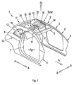
- a structure 2 with opposite side walls 3 and 4 and an upper cross member 5 of a windshield frame 6 is shown.
- Each one door opening 7 and a window opening 8 having side walls 3 and 4, which are upright and fixedly connected to the structure 2, comprise roof side supports 9 and 10.
- the latter go over in a rear region 11 of the structure 2 in columns 12 and 13 and encounter an approximately horizontal belt line 14 of the structure 2
- the roof side supports 9 and 10, the upper cross member 5 and a rear cross member 15 of the body 2 extending adjacent the belt line 14 define a roof opening 16 in which a movable roof 17 is slidably disposed in the vehicle longitudinal direction AA; the direction of travel is designated Fr and a rear window with Hsch.
- the roof 17 is constructed in the manner of a passenger compartment Fgr vaulting folding top 18, z. B. in the US 3,658,368 and DE 807 874 described, and movable between a closed position and an open position. In the open position of the folding top 18 the latter is placed in folds.
- the folding top 18 is provided with a number in the vehicle transverse direction BB extending and spaced in the vehicle longitudinal direction AA rod-like bow.
- the latter are designed as judgessspriegel 19 and 20 and as Faltspriegel 21 and 22, wherein the rougesspriegel 19 and 20 viewed in the direction of travel Fr are respectively in front of the folds 21 and 22.
- Theaimssspriegel 19 and 20 are arranged on both sides of a central longitudinal plane CC guide rails 23 and 24 which extend adjacent to longitudinal sides 25 and 26 of the roof opening 16 and Dachoirelini 9 and 10.
- One possible embodiment of the said guide rails is the DE 10 2008 051 707 A1 refer to.
- the researcherssspriegel 19 and 20 and the folding buckets 21 and 22 carry a top cloth Vb, which consists of flexible material and is placed in the open position of the folding top 18 by means of said bow in defined folds.
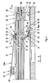
- the folding arch 21 and 22 of the folding top 18 are by means of spring elements 27 and 28 from a lowered basic position Grst Fig. 3 - Almost spent in an erected folding position.
- the elongated, rod-like spring elements 27 and 28 are connected to controls 29 and 30 in operative connection, which hold the spring elements 27 and 28 in the lowered basic position Grst in the closed position of the folding top 18.
- the spring elements 27 and 28 are released in the open position of the folding top 18 by means of the controls 29 and 30 so that they are the established folding position Almost take for the folds 21 and 22.
- the controls 29 and 30 influence the spring elements 27 and 28 in the direction of basic position Grst and Fast by axial movements in the vehicle longitudinal direction AA.
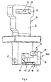
- Each spring element -zB 27- is surrounded by a rectangular recess 31 on all sides, which is arranged at an upper end 32 of a columnar support 33 of the associated control element 29 - Fig. 4 . 7 and 8th , Passed through the recess 31 is the spring element 27, wherein the relative movements of the spring element 27 and the control element 29 by sliding knobs 34 and 35 -.
- Fig. 4 and 7 - Be supported, which are attached to Ausappelungsbegrenzungen 36 and 37 of the recess 31 and cooperate with wall portions 38 and 39 of the spring element 27.
- Leading away from upright boundaries 40 and 41 of the carrier 33 are guide sections 42 and 43 which are displaceable in guide section receptacles -not shown guide rail 23.
- a latching hook device 45 which cooperates with a recess 46 in the guide rail 23.
- the latching hook device 45 is provided with a hook arm 48 hinged to the carrier 33 by means of an axis of rotation 47.
- a fixed to the carrier 31 leaf spring 49 seeks to move the hook arm 48 in a locking position latch.
- a hook portion 51 is provided, which engages in the locking position latching of the latching hook device 45 in the recess 46 of the guide rail 23 and thereby the control element 29 fixed in position.
- the hook arm 48 is actuated by means of a carriage 52 of the guide bow 19 which is movable on the guide rail 23.
- a nose-shaped disengagement element 53 is formed, which adjusts the hook arm 48 in the folded position Fast of the folding latch 20 via a support element 54 provided on the latter in the disengaged position Arst.
- the disengagement element 53 is designed as a control element 55 and the support element 54 is designed as a startup cam 56 ', Fig. 7 and 8th
- the spring element 27 is designed as a leaf spring 57 - Fig. 4 , which at a first end portion 58 has an approximately U-shaped Anformung 59 which rests in an approximately corresponding receptacle 60.
- a second end region 61 of the leaf spring 57 is fixed in a retaining recess 62 of the folding bow 21.
- FIG. 3 again, that the folding top 18 occupy the closed position and the folding bracket 21 and the spring element 27, the basic position Grst.
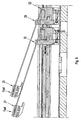
- Fig. 4 is the carriage 52 moves counter to the direction of travel Fr, whereby the spring element 27 is partially shifted in the recess 21 and partially sets up under its spring action in an intermediate position Zwst.
- Fig. 5 shows both the mecanicsspriegel 19 and 20 as well as the folded buckles 21 and 22, wherein the folding buckle 21 is in the erected folding position Fast; the folding jaw 22 in the intermediate position Zwst.
- the latching hook device 45 of the control element 29 is spent on the disengagement element 53 of the carriage 52 from the detent position latch in the disengaged position Arst.
Landscapes
- Engineering & Computer Science (AREA)
- Mechanical Engineering (AREA)
- Body Structure For Vehicles (AREA)
- Lock And Its Accessories (AREA)
Description
- Die Erfindung bezieht sich auf ein Faltverdeck für einen Personenkraftwagen mit einem ein Dach aufweisenden Aufbau, nach dem Oberbegriff des Patentanspruchs 1.
- Es ist eine Faltdachmechanik für ein Faltdach eines Fahrzeugs bekannt,
DE 196 09 917 C1 , welches Faltdach eine Dachöffnung in einem Dach eines Aufbaus des Fahrzeugs abdeckt. Zu beiden Längsseiten der Dachöffnung sind längs verlaufende Führungsschienen vorgesehen, in denen Gleitelemente verschiebbar gelagert sind. An den Gleitelementen sind in Fahrzeugquerrichtung ausgerichtete Spriegel befestigt. Darüber hinaus ist die Faltdachmechanik mit an den Gleitelementen angeordneten Stützfedern versehen, deren freies Ende auf einen quer verlaufenden Faltspriegel einwirkt, und zwar mittels Vorspannung. Jede Stützfeder greift an einem schwenkbeweglichen Stützteil an, das am Gleitelement gelagert ist und den zughörigen Faltspriegel trägt. - In der
DE 693 09 422 T2 wird ein Faltdach zum Schließen und Öffnen einer Dachöffnung in einem Aufbau wiedergegeben. Das einen flexiblen Dachbezug aufweisende Faltdach umfasst Hauptquerglieder und Zwischenquerglieder, die in Fahrzeugquerrichtung zwischen Längsbegrenzungen der Dachöffnung verlaufen. Die Zwischenglieder werden von Blattfedern getragen, die die Zwischenglieder in eine aufgestellte Stellung - Faltposition- zu bewegen suchen. Die jeweilige Blattfeder nimmt an einem Endbereich das entsprechende Zwischenglied auf. Der andere Endbereich ist an einem Führungsschuh befestigt, der in einer Längsschiene verschiebbar ist. - Die
DE 10 2008 051 707 A1 offenbart einen Personenkraftwagen mit einem Faltverdeck, das mit einer Dachöffnung eines Aufbaus des Personenkraftwagens zusammenarbeitet. Ein Verdeckbezug des Faltverdecks wird von Führungsspriegeln und Faltspriegeln getragen. Die Führungsspriegel sind in entlang von Längsseiten der Dachöffnung verlaufenden Führungsschienen verschiebbar. Zwischen jedem Führungsspriegel und jedem Faltspriegel ist benachbart einer Längsseite der Dachöffnung ein Federelement wirksam, das den Faltspriegel bei geöffnetem Faltverdeck in eine aufgestellte Faltstellung bewegt. Das Federelement ist als Blattfeder dargestellt, die mit ihren Enden in Aufnahmen des Führungsspriegels und des Faltspriegels festgelegt ist. - Es ist Aufgabe der Erfindung, ein Faltverdeck mit Führungsspriegeln und durch Federelemente beeinflusste Faltspriegeln für einen Personenkraftwagen zu konzipieren, welche Federelmente die Faltspriegel gezielt zwischen einer abgesenkten Grundstellung und einer aufgestellten Faltstellung verstellen.
- Nach der Erfindung wird diese Aufgabe durch die Merkmale des Patentanspruchs 1 gelöst. Weitere, die Erfindung ausgestaltende Merkmale sind in den Unteransprüchen enthalten.
- Die mit der Erfindung hauptsächlich erzielten Vorteile sind darin zu sehen, dass das Zusammenwirken des Steuerelements mit dem Federelement, angeordnet zwischen Führungsspriegel und Faltespriegel, auf vorbildliche Weise eine zwangsgesteuerte Beeinflussung des Federelements und folglich auch des Faltspriegels ermöglicht. Dank des Steuerelements wird in der Schließstellung des Faltverdecks der Faltspriegel über das Federelement musterhaft in der abgesenkten Grundstellung gehalten, wogegen in der Offenstellung des Faltverdecks das Steuerelement das Federelement lagemäßig freigibt, so dass es den Faltspriegel in seine aufgestellte Faltstellung verstellt. Die Grundstellung und die Faltstellung des Faltspriegels werden durch einfach realisierbare axiale Bewegungen des Steuerelements bewerkstelligt. Die Verbindung des Steuerelements mit dem Federelement über eine Ausnehmung in dem Träger des besagten Steuerelements und seine Führungsabschnitte für die Führungsaufnahmeabschnitte in der Führungsschiene lassen sich ebenso aufwandsarm umsetzen wie auch die Rasthakenvorrichtung des Steuerelements, die mit der Ausnehmung in der Führungsschiene zusammenwirkt. Sinngemäß trifft dies auch für den Hakenarm und die ihn beeinflussbare Schenkelfeder zu. Schließlich stellen der bewegliche Schlitten des Führungsspriegels mit dem Ausrückelement und das Stützelement am Hakenarm ein gezieltes Ausrücken des Hakenelements aus der Ausnehmung in der Führungsschiene sicher.
- In der Zeichnung ist ein Ausführungsbeispiel der Erfindung dargestellt, das nachstehend näher erläutert wird.
- Es zeigen
-
Fig. 1 eine Schrägansicht von rechts oben auf einen schematisch abgebildeten Personenkraftwagen mit einem Faltverdeck, -
Fig. 2 eine Ansicht von oben auf das Dach des Personenkraftwagens gemäßFig. 1 , -
Fig. 3 eine Teilansicht derFig. 2 in Pfeilrichtung X in größerem Maßstab, wobei sich das Faltverdeck in einer Schließstellung und der Faltspriegel in einer abgesenkten Grundstellung befinden, -
Fig. 4 eine Ansicht entsprechendFig. 3 , jedoch der Faltspriegel in einer Zwischenstellung, -
Fig. 5 eine Ansicht entsprechendFig. 2 , jedoch mit zwei Faltspriegeln, wovon der eine Faltspriegel eine abgesenkte Zwischenstellung und der andere Faltspriegel eine aufgestellte Faltstellung einnehmen, -
Fig. 6 eine Ansicht entsprechendFig. 5 , jedoch beide Faltspriegel in aufgestellter Faltstellung, -
Fig. 7 Einzelheiten Y derFig. 1 in größerem Maßstab, -
Fig. 8 eine Schrägansicht auf das Steuerelement mit einem ein Stützelement und einen Anlaufnocken aufweisenden Hakenarm. - Von einem Personenkraftwagen 1 ist ein Aufbau 2 mit gegenüberliegenden Seitenwänden 3 und 4 und einem oberen Querträger 5 eines Windschutzscheibenrahmens 6 dargestellt. Die je eine Türöffnung 7 und eine Fensteröffnung 8 aufweisenden Seitenwände 3 und 4, die aufrecht stehen und fest mit dem Aufbau 2 verbunden sind, umfassen Dachseitenträger 9 und 10. Letztere gehen in einem rückwärtigen Bereich 11 des Aufbaus 2 in Säulen 12 und 13 über und stoßen auf eine etwa horizontal verlaufende Gürtellinie 14 des Aufbaus 2. Die Dachseitenträger 9 und 10, der obere Querträger 5 und ein benachbart der Gürtellinie 14 verlaufendes hinteres Querteil 15 des Aufbaus 2 begrenzen eine Dachöffnung 16, in der ein bewegliches Dach 17 in Fahrzeuglängsrichtung A-A verschiebbar angeordnet ist; die Fahrtrichtung ist mit Fr bezeichnet und eine Heckscheibe mit Hsch.
- Das Dach 17 ist nach Art eines einen Fahrgastraum Fgr überwölbenden Faltverdecks 18 aufgebaut, z. B. in der
US 3,658, 378 undDE 807 874 beschrieben, und zwischen einer Schließstellung und einer Offenstellung bewegbar. In der Offenstellung des Faltverdecks 18 ist letzteres in Falten gelegt. Hierzu ist das Faltverdeck 18 mit einer Anzahl in Fahrzeugquerrichtung B-B verlaufender und in Fahrzeuglängsrichtung A-A beabstandeter stangenartiger Spriegel versehen. Letztere sind als Führungsspriegel 19 und 20 und als Faltspriegel 21 und 22 ausgeführt, wobei die Führungsspriegel 19 und 20 in Fahrtrichtung Fr betrachtet jeweils vor den Faltspriegeln 21 und 22 liegen. Die Führungsspriegel 19 und 20 sind von beiderseits einer Mittellängsebene C-C angeordneten Führungsschienen 23 und 24 aufgenommen, die benachbart von Längsseiten 25 und 26 der Dachöffnung 16 bzw. Dachseitenträger 9 und 10 verlaufen. Eine mögliche Ausführung der besagten Führungsschienen ist derDE 10 2008 051 707 A1 zu entnehmen. Darüber hinaus tragen die Führungsspriegel 19 und 20 und die Faltspriegel 21 und 22 einen Verdeckbezug Vb, der aus flexiblem Werkstoff besteht und in der Offenstellung des Faltverdecks 18 mittels besagter Spriegel in definierte Falten gelegt wird. - Die Faltspriegel 21 und 22 des Faltverdecks 18 werden mittels Federelementen 27 und 28 aus einer abgesenkten Grundstellung Grst -
Fig. 3 - in eine aufgestellte Faltstellung Fast verbracht. Die länglichen, stabartigen Federelemente 27 und 28 stehen mit Steuerelementen 29 und 30 in Wirkverbindung, die in der Schließstellung des Faltverdecks 18 die Federelemente 27 und 28 in der abgesenkten Grundstellung Grst halten. Dagegen werden die Federelemente 27 und 28 in der Offenstellung des Faltverdecks 18 mittels der Steuerelemente 29 und 30 freigegeben, damit sie die aufgestellte Faltstellung Fast für die Faltspriegel 21 und 22 einnehmen. Dabei beeinflussen die Steuerelemente 29 und 30 durch axiale Bewegungen in Fahrzeuglängsrichtung A-A die Federelemente 27 und 28 in Richtung Grundstellung Grst und Fast. - Jedes Federelement -z.B. 27- ist von einer rechteckigen Ausnehmung 31 allseitig umgeben, die an einem oberen Ende 32 eines säulenartigen Trägers 33 des zugehörigen Steuerelements 29 angeordnet ist -
Fig. 4 ,7 und8 . Durch die Ausnehmung 31 hindurchgeführt ist das Federelement 27, wobei die Relativbewegungen des Federelements 27 und des Steuerelements 29 durch Gleitnoppen 34 und 35 -Fig. 4 und7 - unterstützt werden, die an Ausnehmungsbegrenzungen 36 und 37 der Ausnehmung 31 angebracht sind und mit Wandabschnitten 38 und 39 des Federelements 27 zusammenwirken. Von aufrechten Begrenzungen 40 und 41 des Trägers 33 weggeführt sind Führungsabschnitte 42 und 43, die in Führungsabschnittsaufnahmen -nicht dargestelltder Führungsschiene 23 verschiebbar sind. - An einem unteren freien Ende 44 ist der Träger 33 des Steuerelements 29 mit einer Rasthakenvorrichtung 45 ausgestattet, die mit einer Ausnehmung 46 in der Führungsschiene 23 zusammenarbeitet. Die Rasthakenvorrichtung 45 ist mit einem am Träger 33 mittels einer Drehachse 47 angelenkten Hakenarm 48 versehen. Eine am Träger 31 befestigte Blattfeder 49 sucht den Hakenarm 48 in eine Raststellung Rast zu bewegen. An einem freien Ende 50 des Hakenarms 48 ist ein Hakenabschnitt 51 vorgesehen, der in der Raststellung Rast der Rasthakenvorrichtung 45 in die Ausnehmung 46 der Führungsschiene 23 eingreift und dadurch das Steuerelement 29 lagemäßig fixiert..
- Der Hakenarm 48 wird mittels eines auf der Führungsschiene 23 beweglichen Schlittens 52 des Führungsspriegels 19 betätigt. An dem Schlitten 52 ist ein nasenförmiges Ausrückelement 53 angeformt, das in der Faltstellung Fast des Faltspriegels 20 den Hakenarm 48 über ein an letzterem vorgesehenes Stützelement 54 in Ausrückstellung Arst verstellt. Das Ausrückelement 53 ist als Steuerelement 55 und das Stützelement 54 ist als Anlaufnocken 56' ausgeführt -
Fig. 7 und8 . Das Federelement 27 ist als Blattfeder 57 ausgebildet -Fig. 4 , die an einem ersten Endbereich 58 eine etwa U-förmige Anformung 59 besitzt, die in einer annähernd korrespondierenden Aufnahme 60 ruht. Ein zweiter Endbereich 61 der Blattfeder 57 ist in einer Halteausnehmung 62 des Faltspriegels 21 festgelegt. - Die
Fig. 3 gibt wieder, dass das Faltverdeck 18 die Schließstellung und der Faltspriegel 21 sowie das Federelement 27 die Grundstellung Grst einnehmen. InFig. 4 ist der Schlitten 52 entgegen der Fahrtrichtung Fr bewegt, wodurch das Federelement 27 abschnittsweise in der Ausnehmung 21 verschoben ist und sich unter seiner Federwirkung teilweise in eine Zwischenstellung Zwst aufstellt.Fig. 5 zeigt sowohl die Führungsspriegel 19 und 20 wie auch die Faltspriegel 21 und 22, wobei sich der Faltspriegel 21 in der aufgestellten Faltstellung Fast befindet; der Faltspriegel 22 in der Zwischenstellung Zwst. Dabei ist die Rasthakenvorrichtung 45 des Steuerelements 29 über das Ausrückelement 53 des Schlittens 52 aus der Raststellung Rast in die Ausrückstellung Arst verbracht. Das Steuerelement 30 ist jedoch mittels der Rasthakenvorrichtung 45' in der Ausnehmung 46' festgelegt. Schließlich ist ausFig. 6 ersichtlich, dass die Schlitten 52 und 52' der Führungsspriegel 19 bzw. 20 zusammengeführt und die Faltspriegel 21 und 22 die Faltstellung Fast einnehmen.
Claims (11)
- Faltverdeck für einen Personenkraftwagen mit einem ein Dach aufweisenden Aufbau, welches zwischen einer Schließstellung und einer Offenstellung verstellbare Faltverdeck (18) mit einer Dachöffnung zusammenwirkt und einen von an Längsseiten der Dachöffnung angebrachten Führungsschienen (23) aufgenommenen Führungsspriegeln (19, 20) und Faltspriegelnlgen (21, 22) getragenen Verdeckbezug umfasst, wobei die Faltspriegel mittels Federelemente (27, 28) von einer abgesenkten Grundstellung in eine aufgestellte Faltstellung verbracht werden und die Federelemente sowohl an den Führungsspriegeln wie auch an den Faltspriegeln gehalten sind, dadurch gekennzeichnet, dass die Federelemente (27 und 28) mit Steuerelementen (29 und 30) in Wirkverbindung stehen, die in der Schließstellung des Faltverdecks (18) die Federelemente (27 und 28) in der abgesenkten Grundstellung (Grst) halten und dass in der Offenstellung des Faltverdecks die Steuerelemente (29 und 30) die aufgestellte Faltstellung (Fast) der Federelemente (27 und 28) freigeben.
- Faltverdeck nach Anspruch 1, dadurch gekennzeichnet, dass die Steuerelemente (29 und 30) durch axiale Bewegungen in Fahrzeuglängsrichtung (A-A) die Federelemente (27 und 28) in Richtung Grundstellung (Grst) und Faltstellung (Fast) beeinflussen.
- Faltverdeck nach Anspruch 2, dadurch gekennzeichnet, dass jedes Federelement (27, 28) von einer Ausnehmung (31) an einem oberen freien Ende (32) eines säulenartigen Trägers (33) des Steuerelements (29, 30) umgeben ist.
- Faltverdeck nach Anspruch 3, dadurch gekennzeichnet, dass der Träger (33) des Steuerelements (29) mit Führungsabschnitten (42 und 43) in Führungsabschnittsaufnahmen der Führungsschiene (23) verschiebbar ist.
- Faltverdeck nach Anspruch 3, dadurch gekennzeichnet, dass der Träger (33) des Steuerelements (29) an einem unteren freien Ende (44) mit einer Rasthakenvorrichtung (45) versehen ist, die mit einer Ausnehmung (46) in der Führungsschiene (23) zusammenarbeitet.
- Faltverdeck nach Anspruch 5, dadurch gekennzeichnet, dass die Rasthakenvorrichtung (45) einen am Träger (33) mittels einer Drehachse (47) schwenkbar angebrachten Hakenarm (48) umfasst, den eine Blattfeder (57) in eine Raststellung (Rast) zu bewegen sucht.
- Faltverdeck nach den Ansprüchen 5 und 6, dadurch gekennzeichnet, dass an einem freien Ende (50) des Hakenarms (48) der Rasthakenvorrichtung (45) ein Hakenabschnitt (51) vorgesehen ist, der in der Raststellung (Rast) der Rasthakenvorrichtung des Steuerelements (29) in die Ausnehmung (46) der Führungsschiene (23) eingreift.
- Faltverdeck nach Anspruch 6 oder 7, dadurch gekennzeichnet, dass der Hakenarm (48) des Steuerelements (29) mittels eines auf der Führungsschiene (23) beweglichen Schlittens (52, 52') des Führungsspriegels (19; 20) beeinflussbar ist.
- Faltverdeck nach Anspruch 8, dadurch gekennzeichnet, dass am Schlitten ein Ausrückelement (53) vorgesehen ist, das in der Faltstellung (Fast) des Faltspriegels (21) den Hakenarm (48) über ein an diesem angeordneten Stützelement (54) in eine Ausrückstellung (Arst) bewegt.
- Faltverdeck nach Anspruch 9, dadurch gekennzeichnet, dass das Ausrückelement (53) als Steuerelement (55) und das Stützelement (54) als Anlaufnocken (56) ausgeführt sind.
- Faltverdeck nach den Ansprüchen 1 und 8, dadurch gekennzeichnet, dass das Federelement (27; 28) als Blattfeder (57) ausgebildet ist, die einerseits mit einem ersten Endbereich (58) in einer korrespondierenden Aufnahme (60) des Schlittens (52) und andererseits mit einem zweiten Endbereich (60) in einer Halteausnehmung (61) des Faltspriegels (21; 22) festgelegt ist.
Applications Claiming Priority (1)
| Application Number | Priority Date | Filing Date | Title |
|---|---|---|---|
| DE201010027197 DE102010027197A1 (de) | 2010-07-07 | 2010-07-07 | Faltverdeck für einen Personenkraftwagen |
Publications (2)
| Publication Number | Publication Date |
|---|---|
| EP2404773A1 EP2404773A1 (de) | 2012-01-11 |
| EP2404773B1 true EP2404773B1 (de) | 2013-01-09 |
Family
ID=44514393
Family Applications (1)
| Application Number | Title | Priority Date | Filing Date |
|---|---|---|---|
| EP20110005416 Not-in-force EP2404773B1 (de) | 2010-07-07 | 2011-07-01 | Faltverdeck für einen Personenkraftwagen |
Country Status (2)
| Country | Link |
|---|---|
| EP (1) | EP2404773B1 (de) |
| DE (1) | DE102010027197A1 (de) |
Families Citing this family (1)
| Publication number | Priority date | Publication date | Assignee | Title |
|---|---|---|---|---|
| DE102014218447A1 (de) * | 2014-09-15 | 2016-03-17 | Magna Car Top Systems Gmbh | Faltschiebedach für Kraftfahrzeuge |
Family Cites Families (9)
| Publication number | Priority date | Publication date | Assignee | Title |
|---|---|---|---|---|
| DE807874C (de) | 1948-12-29 | 1951-07-05 | Stromag Maschf | Sicherheitsreibungskupplung |
| US2987331A (en) * | 1956-05-29 | 1961-06-06 | Hans T Golde | Closure mechanism |
| FR2053488A5 (de) | 1969-07-07 | 1971-04-16 | Peugeot & Renault | |
| DE2535131C2 (de) * | 1975-08-06 | 1984-03-08 | Ed. Scharwächter GmbH & Co KG, 5630 Remscheid | Schiebeverdeck, insbesondere für LkW und Anhänger |
| EP0336414B1 (de) * | 1988-04-07 | 1994-07-13 | Ohi Seisakusho Co., Ltd. | Stoffschiebedachanordnung für ein Kraftfahrzeug |
| GB9300354D0 (en) | 1993-01-09 | 1993-03-03 | Britax Weathershields | Opening roof for a vehicle |
| DE19608917C1 (de) | 1996-03-07 | 1997-04-10 | Webasto Karosseriesysteme | Faltdachmechanik für ein Faltdach eines Fahrzeuges |
| DE60137805D1 (de) * | 2000-11-09 | 2009-04-09 | Inalfa Roof Sys Group Bv | Offene Dachkonstruktion für ein Fahrzeug sowie Fahrzeug mit einer solchen offenen Dachkonstruktion |
| DE102008051707A1 (de) | 2008-10-01 | 2010-04-08 | Magna Car Top Systems Gmbh | Dach mit einem Faltverdeck für einen Personenkraftwagen |
-
2010
- 2010-07-07 DE DE201010027197 patent/DE102010027197A1/de not_active Withdrawn
-
2011
- 2011-07-01 EP EP20110005416 patent/EP2404773B1/de not_active Not-in-force
Also Published As
| Publication number | Publication date |
|---|---|
| DE102010027197A1 (de) | 2012-01-12 |
| EP2404773A1 (de) | 2012-01-11 |
Similar Documents
| Publication | Publication Date | Title |
|---|---|---|
| WO1996027509A1 (de) | Verriegelungsvorrichtung zum lösbaren befestigen eines fahrzeugdaches an einem unbeweglichen karosserieteil | |
| EP1092578A2 (de) | Kinematisches Verdeck für Pkw | |
| DE3523433C1 (de) | Klappverdeck fuer Fahrzeuge,insbesondere fuer Personenkraftwagen | |
| EP0494356B1 (de) | Faltdach für Fahrzeuge | |
| EP0603834B1 (de) | Faltdach für Fahrzeuge | |
| EP0264560B1 (de) | Hebeschiebedach für Fahrzeuge | |
| DE19803129A1 (de) | Sonnenrollo für Kraftfahrzeug-Heckfenster | |
| DE102008036909B4 (de) | Personenkraftwagen mit einem verstellbaren Dach | |
| EP2404773A1 (de) | Faltverdeck für einen Personenkraftwagen | |
| EP2468546B1 (de) | Faltverdeck eines Fahrzeugs | |
| EP2428378A2 (de) | Lenker für ein Faltdach | |
| DE102008026547B4 (de) | Faltdach eines Kraftfahrzeugs mit Ausstellspriegel | |
| EP2172355B1 (de) | Faltverdeck für ein Dach eines Aufbaus eines Personenkraftwagens | |
| EP2404774B1 (de) | Dachkappe für ein Faltverdeck | |
| DE102004045906A1 (de) | Gestell für ein verschlebbares, von einer Plane überspanntes Dach eines Nutzaufbaus | |
| EP3536528B1 (de) | Cabriolet-fahrzeug | |
| DE102008051707A1 (de) | Dach mit einem Faltverdeck für einen Personenkraftwagen | |
| DE102012002286B4 (de) | Fahrzeugdach mit einem verstellbaren Faltverdeck | |
| DE4317480C2 (de) | Fahrzeugsitz, insbesondere für Nutzfahrzeuge | |
| DE102009009350B4 (de) | Faltverdeck und Fahrzeug | |
| DE102013105013B4 (de) | Fahrzeug, insbesondere Cabriolet-Fahrzeug mit einer Verdeckauflage | |
| EP2298583B1 (de) | Faltverdeck für einen Personenkraftwagen | |
| DE102013012830B3 (de) | Faltbares Verdeck für ein Cabriolet-Fahrzeug mit einem höhenverstellbaren Dachspriegel sowie Cabriolet-Fahrzeug mit einem solchen faltbaren Verdeck | |
| DE102009055997B3 (de) | Innenverkleidung für ein Faltverdeck | |
| DE102012002289A1 (de) | Fahrzeugdach mit einem verstellbaren Faltverdeck |
Legal Events
| Date | Code | Title | Description |
|---|---|---|---|
| AK | Designated contracting states |
Kind code of ref document: A1 Designated state(s): AL AT BE BG CH CY CZ DE DK EE ES FI FR GB GR HR HU IE IS IT LI LT LU LV MC MK MT NL NO PL PT RO RS SE SI SK SM TR |
|
| AX | Request for extension of the european patent |
Extension state: BA ME |
|
| PUAI | Public reference made under article 153(3) epc to a published international application that has entered the european phase |
Free format text: ORIGINAL CODE: 0009012 |
|
| 17P | Request for examination filed |
Effective date: 20120620 |
|
| GRAP | Despatch of communication of intention to grant a patent |
Free format text: ORIGINAL CODE: EPIDOSNIGR1 |
|
| RIC1 | Information provided on ipc code assigned before grant |
Ipc: B60J 7/06 20060101AFI20120831BHEP |
|
| GRAS | Grant fee paid |
Free format text: ORIGINAL CODE: EPIDOSNIGR3 |
|
| GRAA | (expected) grant |
Free format text: ORIGINAL CODE: 0009210 |
|
| AK | Designated contracting states |
Kind code of ref document: B1 Designated state(s): AL AT BE BG CH CY CZ DE DK EE ES FI FR GB GR HR HU IE IS IT LI LT LU LV MC MK MT NL NO PL PT RO RS SE SI SK SM TR |
|
| REG | Reference to a national code |
Ref country code: GB Ref legal event code: FG4D Free format text: NOT ENGLISH |
|
| REG | Reference to a national code |
Ref country code: CH Ref legal event code: EP Ref country code: AT Ref legal event code: REF Ref document number: 592520 Country of ref document: AT Kind code of ref document: T Effective date: 20130115 |
|
| REG | Reference to a national code |
Ref country code: IE Ref legal event code: FG4D Free format text: LANGUAGE OF EP DOCUMENT: GERMAN |
|
| REG | Reference to a national code |
Ref country code: DE Ref legal event code: R096 Ref document number: 502011000325 Country of ref document: DE Effective date: 20130307 |
|
| PG25 | Lapsed in a contracting state [announced via postgrant information from national office to epo] |
Ref country code: SI Free format text: LAPSE BECAUSE OF FAILURE TO SUBMIT A TRANSLATION OF THE DESCRIPTION OR TO PAY THE FEE WITHIN THE PRESCRIBED TIME-LIMIT Effective date: 20130109 |
|
| REG | Reference to a national code |
Ref country code: NL Ref legal event code: VDEP Effective date: 20130109 |
|
| REG | Reference to a national code |
Ref country code: LT Ref legal event code: MG4D |
|
| PG25 | Lapsed in a contracting state [announced via postgrant information from national office to epo] |
Ref country code: LT Free format text: LAPSE BECAUSE OF FAILURE TO SUBMIT A TRANSLATION OF THE DESCRIPTION OR TO PAY THE FEE WITHIN THE PRESCRIBED TIME-LIMIT Effective date: 20130109 Ref country code: BG Free format text: LAPSE BECAUSE OF FAILURE TO SUBMIT A TRANSLATION OF THE DESCRIPTION OR TO PAY THE FEE WITHIN THE PRESCRIBED TIME-LIMIT Effective date: 20130409 Ref country code: NO Free format text: LAPSE BECAUSE OF FAILURE TO SUBMIT A TRANSLATION OF THE DESCRIPTION OR TO PAY THE FEE WITHIN THE PRESCRIBED TIME-LIMIT Effective date: 20130409 Ref country code: SE Free format text: LAPSE BECAUSE OF FAILURE TO SUBMIT A TRANSLATION OF THE DESCRIPTION OR TO PAY THE FEE WITHIN THE PRESCRIBED TIME-LIMIT Effective date: 20130109 Ref country code: IS Free format text: LAPSE BECAUSE OF FAILURE TO SUBMIT A TRANSLATION OF THE DESCRIPTION OR TO PAY THE FEE WITHIN THE PRESCRIBED TIME-LIMIT Effective date: 20130509 Ref country code: ES Free format text: LAPSE BECAUSE OF FAILURE TO SUBMIT A TRANSLATION OF THE DESCRIPTION OR TO PAY THE FEE WITHIN THE PRESCRIBED TIME-LIMIT Effective date: 20130420 |
|
| PG25 | Lapsed in a contracting state [announced via postgrant information from national office to epo] |
Ref country code: LV Free format text: LAPSE BECAUSE OF FAILURE TO SUBMIT A TRANSLATION OF THE DESCRIPTION OR TO PAY THE FEE WITHIN THE PRESCRIBED TIME-LIMIT Effective date: 20130109 Ref country code: NL Free format text: LAPSE BECAUSE OF FAILURE TO SUBMIT A TRANSLATION OF THE DESCRIPTION OR TO PAY THE FEE WITHIN THE PRESCRIBED TIME-LIMIT Effective date: 20130109 Ref country code: FI Free format text: LAPSE BECAUSE OF FAILURE TO SUBMIT A TRANSLATION OF THE DESCRIPTION OR TO PAY THE FEE WITHIN THE PRESCRIBED TIME-LIMIT Effective date: 20130109 Ref country code: PL Free format text: LAPSE BECAUSE OF FAILURE TO SUBMIT A TRANSLATION OF THE DESCRIPTION OR TO PAY THE FEE WITHIN THE PRESCRIBED TIME-LIMIT Effective date: 20130109 Ref country code: GR Free format text: LAPSE BECAUSE OF FAILURE TO SUBMIT A TRANSLATION OF THE DESCRIPTION OR TO PAY THE FEE WITHIN THE PRESCRIBED TIME-LIMIT Effective date: 20130410 Ref country code: PT Free format text: LAPSE BECAUSE OF FAILURE TO SUBMIT A TRANSLATION OF THE DESCRIPTION OR TO PAY THE FEE WITHIN THE PRESCRIBED TIME-LIMIT Effective date: 20130509 |
|
| PG25 | Lapsed in a contracting state [announced via postgrant information from national office to epo] |
Ref country code: HR Free format text: LAPSE BECAUSE OF FAILURE TO SUBMIT A TRANSLATION OF THE DESCRIPTION OR TO PAY THE FEE WITHIN THE PRESCRIBED TIME-LIMIT Effective date: 20130109 Ref country code: RS Free format text: LAPSE BECAUSE OF FAILURE TO SUBMIT A TRANSLATION OF THE DESCRIPTION OR TO PAY THE FEE WITHIN THE PRESCRIBED TIME-LIMIT Effective date: 20130109 |
|
| PG25 | Lapsed in a contracting state [announced via postgrant information from national office to epo] |
Ref country code: CZ Free format text: LAPSE BECAUSE OF FAILURE TO SUBMIT A TRANSLATION OF THE DESCRIPTION OR TO PAY THE FEE WITHIN THE PRESCRIBED TIME-LIMIT Effective date: 20130109 Ref country code: SK Free format text: LAPSE BECAUSE OF FAILURE TO SUBMIT A TRANSLATION OF THE DESCRIPTION OR TO PAY THE FEE WITHIN THE PRESCRIBED TIME-LIMIT Effective date: 20130109 Ref country code: EE Free format text: LAPSE BECAUSE OF FAILURE TO SUBMIT A TRANSLATION OF THE DESCRIPTION OR TO PAY THE FEE WITHIN THE PRESCRIBED TIME-LIMIT Effective date: 20130109 Ref country code: DK Free format text: LAPSE BECAUSE OF FAILURE TO SUBMIT A TRANSLATION OF THE DESCRIPTION OR TO PAY THE FEE WITHIN THE PRESCRIBED TIME-LIMIT Effective date: 20130109 Ref country code: RO Free format text: LAPSE BECAUSE OF FAILURE TO SUBMIT A TRANSLATION OF THE DESCRIPTION OR TO PAY THE FEE WITHIN THE PRESCRIBED TIME-LIMIT Effective date: 20130109 |
|
| PLBE | No opposition filed within time limit |
Free format text: ORIGINAL CODE: 0009261 |
|
| STAA | Information on the status of an ep patent application or granted ep patent |
Free format text: STATUS: NO OPPOSITION FILED WITHIN TIME LIMIT |
|
| PG25 | Lapsed in a contracting state [announced via postgrant information from national office to epo] |
Ref country code: CY Free format text: LAPSE BECAUSE OF FAILURE TO SUBMIT A TRANSLATION OF THE DESCRIPTION OR TO PAY THE FEE WITHIN THE PRESCRIBED TIME-LIMIT Effective date: 20130109 |
|
| 26N | No opposition filed |
Effective date: 20131010 |
|
| REG | Reference to a national code |
Ref country code: DE Ref legal event code: R097 Ref document number: 502011000325 Country of ref document: DE Effective date: 20131010 |
|
| BERE | Be: lapsed |
Owner name: MAGNA CAR TOP SYSTEMS G.M.B.H. Effective date: 20130731 |
|
| PG25 | Lapsed in a contracting state [announced via postgrant information from national office to epo] |
Ref country code: MC Free format text: LAPSE BECAUSE OF FAILURE TO SUBMIT A TRANSLATION OF THE DESCRIPTION OR TO PAY THE FEE WITHIN THE PRESCRIBED TIME-LIMIT Effective date: 20130109 |
|
| REG | Reference to a national code |
Ref country code: IE Ref legal event code: MM4A |
|
| PG25 | Lapsed in a contracting state [announced via postgrant information from national office to epo] |
Ref country code: BE Free format text: LAPSE BECAUSE OF NON-PAYMENT OF DUE FEES Effective date: 20130731 |
|
| PG25 | Lapsed in a contracting state [announced via postgrant information from national office to epo] |
Ref country code: IE Free format text: LAPSE BECAUSE OF NON-PAYMENT OF DUE FEES Effective date: 20130701 |
|
| PGFP | Annual fee paid to national office [announced via postgrant information from national office to epo] |
Ref country code: IT Payment date: 20140731 Year of fee payment: 4 |
|
| REG | Reference to a national code |
Ref country code: CH Ref legal event code: PL |
|
| PG25 | Lapsed in a contracting state [announced via postgrant information from national office to epo] |
Ref country code: LI Free format text: LAPSE BECAUSE OF NON-PAYMENT OF DUE FEES Effective date: 20140731 Ref country code: CH Free format text: LAPSE BECAUSE OF NON-PAYMENT OF DUE FEES Effective date: 20140731 |
|
| PG25 | Lapsed in a contracting state [announced via postgrant information from national office to epo] |
Ref country code: SM Free format text: LAPSE BECAUSE OF FAILURE TO SUBMIT A TRANSLATION OF THE DESCRIPTION OR TO PAY THE FEE WITHIN THE PRESCRIBED TIME-LIMIT Effective date: 20130109 |
|
| PG25 | Lapsed in a contracting state [announced via postgrant information from national office to epo] |
Ref country code: MT Free format text: LAPSE BECAUSE OF FAILURE TO SUBMIT A TRANSLATION OF THE DESCRIPTION OR TO PAY THE FEE WITHIN THE PRESCRIBED TIME-LIMIT Effective date: 20130109 Ref country code: TR Free format text: LAPSE BECAUSE OF FAILURE TO SUBMIT A TRANSLATION OF THE DESCRIPTION OR TO PAY THE FEE WITHIN THE PRESCRIBED TIME-LIMIT Effective date: 20130109 |
|
| PG25 | Lapsed in a contracting state [announced via postgrant information from national office to epo] |
Ref country code: HU Free format text: LAPSE BECAUSE OF FAILURE TO SUBMIT A TRANSLATION OF THE DESCRIPTION OR TO PAY THE FEE WITHIN THE PRESCRIBED TIME-LIMIT; INVALID AB INITIO Effective date: 20110701 Ref country code: MK Free format text: LAPSE BECAUSE OF FAILURE TO SUBMIT A TRANSLATION OF THE DESCRIPTION OR TO PAY THE FEE WITHIN THE PRESCRIBED TIME-LIMIT Effective date: 20130109 Ref country code: LU Free format text: LAPSE BECAUSE OF NON-PAYMENT OF DUE FEES Effective date: 20130701 |
|
| PG25 | Lapsed in a contracting state [announced via postgrant information from national office to epo] |
Ref country code: IT Free format text: LAPSE BECAUSE OF NON-PAYMENT OF DUE FEES Effective date: 20150701 |
|
| REG | Reference to a national code |
Ref country code: FR Ref legal event code: PLFP Year of fee payment: 6 |
|
| REG | Reference to a national code |
Ref country code: FR Ref legal event code: PLFP Year of fee payment: 7 |
|
| REG | Reference to a national code |
Ref country code: AT Ref legal event code: MM01 Ref document number: 592520 Country of ref document: AT Kind code of ref document: T Effective date: 20160701 |
|
| PG25 | Lapsed in a contracting state [announced via postgrant information from national office to epo] |
Ref country code: AT Free format text: LAPSE BECAUSE OF NON-PAYMENT OF DUE FEES Effective date: 20160701 |
|
| REG | Reference to a national code |
Ref country code: FR Ref legal event code: PLFP Year of fee payment: 8 |
|
| PG25 | Lapsed in a contracting state [announced via postgrant information from national office to epo] |
Ref country code: AL Free format text: LAPSE BECAUSE OF FAILURE TO SUBMIT A TRANSLATION OF THE DESCRIPTION OR TO PAY THE FEE WITHIN THE PRESCRIBED TIME-LIMIT Effective date: 20130109 |
|
| REG | Reference to a national code |
Ref country code: DE Ref legal event code: R084 Ref document number: 502011000325 Country of ref document: DE |
|
| PGFP | Annual fee paid to national office [announced via postgrant information from national office to epo] |
Ref country code: DE Payment date: 20240719 Year of fee payment: 14 |
|
| PGFP | Annual fee paid to national office [announced via postgrant information from national office to epo] |
Ref country code: GB Payment date: 20240723 Year of fee payment: 14 |
|
| PGFP | Annual fee paid to national office [announced via postgrant information from national office to epo] |
Ref country code: FR Payment date: 20240730 Year of fee payment: 14 |
|
| REG | Reference to a national code |
Ref country code: DE Ref legal event code: R082 Ref document number: 502011000325 Country of ref document: DE Representative=s name: EULER, MATTHIAS, DR., DE |
|
| REG | Reference to a national code |
Ref country code: DE Ref legal event code: R119 Ref document number: 502011000325 Country of ref document: DE |
|
| GBPC | Gb: european patent ceased through non-payment of renewal fee |
Effective date: 20250701 |
|
| PG25 | Lapsed in a contracting state [announced via postgrant information from national office to epo] |
Ref country code: GB Free format text: LAPSE BECAUSE OF NON-PAYMENT OF DUE FEES Effective date: 20250701 |
|
| PG25 | Lapsed in a contracting state [announced via postgrant information from national office to epo] |
Ref country code: DE Free format text: LAPSE BECAUSE OF NON-PAYMENT OF DUE FEES Effective date: 20260203 |
|
| PG25 | Lapsed in a contracting state [announced via postgrant information from national office to epo] |
Ref country code: FR Free format text: LAPSE BECAUSE OF NON-PAYMENT OF DUE FEES Effective date: 20250731 |