EP2402131A1 - Scribing apparatus and scribing method - Google Patents
Scribing apparatus and scribing method Download PDFInfo
- Publication number
- EP2402131A1 EP2402131A1 EP10745945A EP10745945A EP2402131A1 EP 2402131 A1 EP2402131 A1 EP 2402131A1 EP 10745945 A EP10745945 A EP 10745945A EP 10745945 A EP10745945 A EP 10745945A EP 2402131 A1 EP2402131 A1 EP 2402131A1
- Authority
- EP
- European Patent Office
- Prior art keywords
- scribing
- substrate
- brittle material
- substrates
- edge
- Prior art date
- Legal status (The legal status is an assumption and is not a legal conclusion. Google has not performed a legal analysis and makes no representation as to the accuracy of the status listed.)
- Withdrawn
Links
- 238000000034 method Methods 0.000 title claims description 36
- 239000000758 substrate Substances 0.000 claims abstract description 159
- 239000000463 material Substances 0.000 abstract description 8
- 239000011295 pitch Substances 0.000 description 13
- 238000005520 cutting process Methods 0.000 description 8
- 239000000919 ceramic Substances 0.000 description 6
- 238000010586 diagram Methods 0.000 description 6
- 239000011521 glass Substances 0.000 description 4
- 238000013500 data storage Methods 0.000 description 3
- 238000006073 displacement reaction Methods 0.000 description 3
- 230000000149 penetrating effect Effects 0.000 description 3
- 230000015572 biosynthetic process Effects 0.000 description 2
- 238000010276 construction Methods 0.000 description 2
- 229910003460 diamond Inorganic materials 0.000 description 2
- 239000010432 diamond Substances 0.000 description 2
- 230000000694 effects Effects 0.000 description 2
- 238000005096 rolling process Methods 0.000 description 2
- PNEYBMLMFCGWSK-UHFFFAOYSA-N aluminium oxide Inorganic materials [O-2].[O-2].[O-2].[Al+3].[Al+3] PNEYBMLMFCGWSK-UHFFFAOYSA-N 0.000 description 1
- 239000004020 conductor Substances 0.000 description 1
- 238000010304 firing Methods 0.000 description 1
- 238000013467 fragmentation Methods 0.000 description 1
- 238000006062 fragmentation reaction Methods 0.000 description 1
- 239000004973 liquid crystal related substance Substances 0.000 description 1
- 230000014759 maintenance of location Effects 0.000 description 1
- 230000002093 peripheral effect Effects 0.000 description 1
- 238000002360 preparation method Methods 0.000 description 1
- 238000009877 rendering Methods 0.000 description 1
- 230000000630 rising effect Effects 0.000 description 1
Images


Classifications
-
- C—CHEMISTRY; METALLURGY
- C03—GLASS; MINERAL OR SLAG WOOL
- C03B—MANUFACTURE, SHAPING, OR SUPPLEMENTARY PROCESSES
- C03B33/00—Severing cooled glass
- C03B33/02—Cutting or splitting sheet glass or ribbons; Apparatus or machines therefor
- C03B33/023—Cutting or splitting sheet glass or ribbons; Apparatus or machines therefor the sheet or ribbon being in a horizontal position
- C03B33/033—Apparatus for opening score lines in glass sheets
-
- B—PERFORMING OPERATIONS; TRANSPORTING
- B28—WORKING CEMENT, CLAY, OR STONE
- B28D—WORKING STONE OR STONE-LIKE MATERIALS
- B28D5/00—Fine working of gems, jewels, crystals, e.g. of semiconductor material; apparatus or devices therefor
- B28D5/0005—Fine working of gems, jewels, crystals, e.g. of semiconductor material; apparatus or devices therefor by breaking, e.g. dicing
- B28D5/0011—Fine working of gems, jewels, crystals, e.g. of semiconductor material; apparatus or devices therefor by breaking, e.g. dicing with preliminary treatment, e.g. weakening by scoring
-
- B—PERFORMING OPERATIONS; TRANSPORTING
- B28—WORKING CEMENT, CLAY, OR STONE
- B28D—WORKING STONE OR STONE-LIKE MATERIALS
- B28D1/00—Working stone or stone-like materials, e.g. brick, concrete or glass, not provided for elsewhere; Machines, devices, tools therefor
- B28D1/22—Working stone or stone-like materials, e.g. brick, concrete or glass, not provided for elsewhere; Machines, devices, tools therefor by cutting, e.g. incising
- B28D1/24—Working stone or stone-like materials, e.g. brick, concrete or glass, not provided for elsewhere; Machines, devices, tools therefor by cutting, e.g. incising with cutting discs
-
- B—PERFORMING OPERATIONS; TRANSPORTING
- B28—WORKING CEMENT, CLAY, OR STONE
- B28D—WORKING STONE OR STONE-LIKE MATERIALS
- B28D5/00—Fine working of gems, jewels, crystals, e.g. of semiconductor material; apparatus or devices therefor
-
- B—PERFORMING OPERATIONS; TRANSPORTING
- B28—WORKING CEMENT, CLAY, OR STONE
- B28D—WORKING STONE OR STONE-LIKE MATERIALS
- B28D5/00—Fine working of gems, jewels, crystals, e.g. of semiconductor material; apparatus or devices therefor
- B28D5/0058—Accessories specially adapted for use with machines for fine working of gems, jewels, crystals, e.g. of semiconductor material
- B28D5/0064—Devices for the automatic drive or the program control of the machines
-
- B—PERFORMING OPERATIONS; TRANSPORTING
- B28—WORKING CEMENT, CLAY, OR STONE
- B28D—WORKING STONE OR STONE-LIKE MATERIALS
- B28D5/00—Fine working of gems, jewels, crystals, e.g. of semiconductor material; apparatus or devices therefor
- B28D5/0058—Accessories specially adapted for use with machines for fine working of gems, jewels, crystals, e.g. of semiconductor material
- B28D5/0082—Accessories specially adapted for use with machines for fine working of gems, jewels, crystals, e.g. of semiconductor material for supporting, holding, feeding, conveying or discharging work
-
- C—CHEMISTRY; METALLURGY
- C03—GLASS; MINERAL OR SLAG WOOL
- C03B—MANUFACTURE, SHAPING, OR SUPPLEMENTARY PROCESSES
- C03B33/00—Severing cooled glass
- C03B33/02—Cutting or splitting sheet glass or ribbons; Apparatus or machines therefor
- C03B33/023—Cutting or splitting sheet glass or ribbons; Apparatus or machines therefor the sheet or ribbon being in a horizontal position
- C03B33/027—Scoring tool holders; Driving mechanisms therefor
-
- C—CHEMISTRY; METALLURGY
- C03—GLASS; MINERAL OR SLAG WOOL
- C03B—MANUFACTURE, SHAPING, OR SUPPLEMENTARY PROCESSES
- C03B33/00—Severing cooled glass
- C03B33/02—Cutting or splitting sheet glass or ribbons; Apparatus or machines therefor
- C03B33/023—Cutting or splitting sheet glass or ribbons; Apparatus or machines therefor the sheet or ribbon being in a horizontal position
- C03B33/037—Controlling or regulating
Definitions
- the present invention relates to a scribing apparatus and a scribing method used particularly in the cutting of a substrate made of a brittle material such as a low-temperature co-fired ceramic substrate.
- a low-temperature co-fired ceramic (hereafter referred to as "LTCC”) substrate is constructed by performing conductor wiring on sheets obtained by mixing an aggregate of alumina and a glass material thereby to form a multilayer film, followed by firing the multilayer film at a temperature as low as about 800 deg. C.
- the LTCC substrate comprises a single mother board on which a plurality of functional areas are formed simultaneously in a lattice pattern, and the mother board is divided into separate small substrates on a functional area-by-functional area basis.
- a cutting tool whereby the mother board is broken into pieces by means of mechanical cutting.
- the substrate made of such a brittle material is scribed by a scribing apparatus first, and is whereafter cut into pieces along the resulting scribe lines.
- scribing refers to an operation to engrave scribe lines (guide lines for cutting) on a substrate made of a brittle material by rolling a scribing wheel over the substrate in a mutually pressure-contact state.
- the substrate formed with the scribe lines can be fragmented readily simply by causing development of a vertical crack (a crack which runs in the direction of thickness of the substrate).
- a single brittle material-made substrate is held in place on a table in preparation for scribing.
- scribing can be completed in a relatively short period of time.
- much time and effort need to be spent on the retention of the brittle material-made substrates and the removal of the substrates after the completion of scribing.
- the present invention has been devised to solve the problems associated with the conventional art as mentioned supra, and accordingly its object is to provide the capability of scribing small-sized substrates with enhanced workability.
- a scribing apparatus of the present invention for scribing a brittle material-made substrate having functional areas formed thereon to facilitate division of the substrate into separate substrate products on a functional area-by-functional area basis, wherein an inside scribing to scribe said brittle material-made substrate from a position spaced inwardly of one edge of the substrate to a position spaced inwardly of the other edge of the substrate, and an outside scribing to scribe said brittle material-made substrate from a position spaced outwardly of one edge of the substrate to a position spaced outwardly of the other edge of the substrate are employed, comprises: a table on which a plurality of said brittle material-made substrates are arranged while being positioned; a scribing head mounted face to face with the brittle material-made substrate placed on said table for free up-and-down motion, a front end of which is formed with a scribing wheel; a moving section for allowing relative movement
- said table may be provided with a plurality of positioning pins capable of positioning of a plurality of said brittle material-made substrates.
- said scribing wheel may be a scribing wheel with high penetrability.
- a scribing method of the present invention for scribing a brittle material-made substrate having functional areas formed thereon with use of a scribing head which is free to move up and down to facilitate division of the substrate into separate substrate products on a functional area-by-functional area basis, wherein an inside scribing to scribe said brittle material-made substrate from a position spaced inwardly of one edge of the substrate to a position spaced inwardly of the other edge of the substrate, and an outside scribing to scribe said brittle material-made substrate from a position spaced outwardly of one edge of the substrate to a position spaced outwardly of the other edge of the substrate are employed, comprises the steps of: providing in advance a recipe data table for each of a plurality of brittle material-made substrates on an individual basis, said recipe data table containing data on scribe lines to be drawn and corresponding scribing methods; arranging and positioning a plurality of brittle material
- a plurality of small-sized brittle material-made substrates can be put all together on a table so as to be scribed by one operation under automatic control. This makes it possible to save a person in charge who operates the scribing apparatus from having to do a lot of work, and thereby achieve improvement in workability.
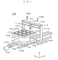
- Fig. 1 is a schematic perspective view showing an example of a scribing apparatus in accordance with an embodiment of the present invention.
- a movable base 101 is mounted for free movement in a y-axis direction along a pair of guide rails 102a and 102b.
- a ball screw 103 threadedly engages the movable base 101.
- the ball screw 103 is rotated by the actuation of a motor 104, thereby allowing the movable base 101 to move in the y-axis direction along the guide rails 102a and 102b.
- a motor 105 for turning a table 106 on an x-y plane so that the table can be positioned at a predetermined angle.
- a plurality of brittle material-made substrates 107 for example, low-temperature co-fired ceramic substrates. The substrates are held in place by means of vacuum suction or otherwise (not represented graphically).
- two CCD cameras 108a and 108b for taking images of alignment marks of each brittle material-made substrate 107.
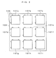
- a plurality of, in this example, nine brittle material-made substrates 107a to 107i are put all together on the table 106 so as to be arranged at a predetermined spacing.
- four positioning pins 109 are disposed perpendicularly to the x-y plane on the table 106 on a substrate-by-substrate basis. A user puts the brittle material-made substrate on the table, with two sides thereof contacted by the nine positioning pins 109 for positioning.
- a bridge 110 extending along an x-axis direction is laid across support columns 111a and 111b so as to straddle the movable base 101 and the table 106 placed above the movable base 101.
- a scribing head 112 is held so as to be moved freely by a linear motor 113.
- the linear motor 113 drives the scribing head 112 to move rectilinearly along the x-axis direction.
- a scribing wheel 115 is attached to the front end of the scribing head 112 via a holder 114.
- the scribing head 112 draws a scribe line by rolling the scribing wheel 115 on the surface of the brittle material-made substrate in a mutually pressure-contact state under an adequate load.
- the scribing wheel 115 a highly penetrative scribing wheel as disclosed in Japanese Patent No. 3074153 is desirable for use. Therefore a scribing wheel of this type is used in this embodiment.
- the scribing wheel having high penetrability can be obtained by forming grooves of predetermined depth with a predetermined pitch at the cutting edge of an ordinary scribing wheel in common use.
- the commonly-used ordinary scribing wheel is fabricated by forming V-shaped blades along the circumference of a disk-shaped wheel.
- the convergent angle of the V-shaped blade is set at an obtuse angle, for example, an angle of greater than or equal to 90-degree, preferably an angle of greater than or equal to 95-degree, or more preferably an angle of greater than or equal to 100-degree, while being set at an angle of less than or equal to 160-degree, preferably an angle of less than or equal to 150-degree, or more preferably an angle of less than or equal to 140-degree.
- the V-shaped blade is formed by grinding the disk-shaped wheel circumferentially so as to form an outer peripheral portion.
- the V-shaped blades formed by grinding operation have the form of minute serrations resulting from grinding marks.
- deeper recesses each of which extends beyond the valley part of the serration at the cutting edge of an ordinary scribing wheel, are arranged at regular intervals at the cutting edge.
- the depth of the groove is greater than or equal to 2 ⁇ m, preferably greater than or equal to 3 ⁇ m, or more preferably greater than or equal to 5 ⁇ m, while being less than or equal to 100 ⁇ m, preferably less than or equal to 50 ⁇ m, or more preferably less than or equal to 20 ⁇ m.
- the width of the groove is greater than or equal to 10 ⁇ m, preferably greater than or equal to 150 ⁇ m, or more preferably greater than or equal to 20 ⁇ m, while being less than or equal to 100 ⁇ m, or preferably less than or equal to 50 ⁇ m.
- the pitch of the grooves is, given that the scribing wheel has a diameter in a 1 mm to 10 mm range (especially in a 1.5 mm- to 7 mm range) for example, set to fall in a range from 20 ⁇ m to 250 ⁇ m, preferably from 30 ⁇ m to 180 ⁇ m, or more preferably from 40 ⁇ m to 80 ⁇ m.
- the pitch takes on a value obtained by summing the length of a single groove in a direction circumferentially of the scribing wheel and the length of a single protrusion resulting from formation of the groove.
- the length of a single groove is longer than the length of a single protrusion in the circumferential direction of the scribing wheel.
- Exemplary of the material of construction of the scribing wheel are sintered diamond (PCD), cemented carbide, and the like. In the interest of a long service life of the scribing wheel, sintered diamond (PCD) is desirable for use.
- the movable base 101, the guide rails 102a and 102b, the table 106, the motors 104 and 105 for driving them, and the linear motor 113 for driving the scribing head 112 constitute a moving section for effecting relative movement of the scribing head and the brittle material-made substrate within the range of the plane of the substrate.
- Fig. 3 is the block diagram of the controller 120 of the scribing apparatus 100.
- output from the two CCD cameras 108a and 108b is fed, through an image processing section 121 of the controller 120, to a control section 122.
- An input section 123 is provided for the input of recipe data about scribing of the brittle material-made substrate, which will hereafter be described.
- the control section 122 is connected with a Y motor driver 125, a turning motor driver 126, and a scribing head driver 127.
- the Y motor driver 125 drives the motor 104.
- the turning motor driver 126 drives the motor 105.
- the control section 122 controls the position of the table 106 in the y-axis direction and exercises turning control over the table 106.
- the scribing head 112 is driven to move in the x-axis direction by the scribing head driver 127, and also the scribing wheel 115 is driven to roll over the surface of the brittle material-made substrate in a mutually pressure-contact state under an adequate load.
- the control section 122 is connected with a monitor 128 and a recipe data storage section 129.
- the recipe data storage section 129 stores therein recipe data tables a to i for scribing the nine brittle material-made substrates 107a to 107i, respectively.
- the recipe data is inputted through the input section 123 while being monitored by the monitor 128.
- the brittle material-made substrate is scribed from one lateral side to the other lateral side. More specifically, referring to Fig. 4 , in the outside scribing, the scribing wheel 115 is set in a position spaced outwardly a slight distance from one end of the brittle material-made substrate 107, and is lowered until its lowermost part comes to a position slightly lower than the top surface of the brittle material-made substrate 107.
- the scribing wheel 115 is moved horizontally toward the right, as viewed in the figure, under a predetermined scribing pressure. In this way, the brittle material-made substrate 107 is scribed from one edge to the other edge.
- the outside scribing since the resulting scribe line extends from one edge to the other edge of the substrate, it follows that the substrate can be fragmented (broken) readily after scribing operation.
- the outside scribing is free from the problem of a slip of the scribing wheel at the scribing starting point.
- the negative side is that the scribing wheel is susceptible to wear.
- the scribing wheel 115 is set and lowered in a position spaced inwardly a slight distance from one edge of the brittle material-made substrate 107, and is then moved horizontally toward the right, as viewed in the figure, under a predetermined scribing pressure. In this way, scribing is started from within the brittle material-made substrate 107.
- the brittle material-made substrate 107 is scribed from a position spaced inwardly from one edge to a position spaced inwardly from the other edge. That is, the brittle material-made substrate 107 is not scribed at its opposite lateral edge.
- the scribing wheel In the inside scribing, the scribing wheel is lowered in a position spaced inwardly from one edge of the brittle material-made substrate 107. In this case, a vertical crack resulting from scribing operation is likely to have a shallow depth. With this in view, in this embodiment, a cutting edge having high penetrability is used for the scribing wheel 115. Accordingly, even in the case of the inside scribing, a sufficiently deep vertical crack can be developed.
- scribing operation is conducted while adopting the outside scribing and the inside scribing separately for individual scribe lines.
- Fig. 6 is a diagram showing a single brittle material-made substrate 107a and twenty functional areas formed in a lattice pattern on the surface of the substrate.
- the substrate bears previously formed alignment marks located among the functional areas. Out of the alignment marks, the ones arranged along the periphery of the substrate are indicated with symbols a to r, respectively.
- step S11 as shown in Fig. 4 , an overhang amount OH1 at the start of the outside scribing and an overhang amount OH2 at the end of the outside scribing are determined.
- overhang amount refers to the distance from the edge of the substrate to the lowering or rising position of the scribing head.
- the amount of an overhang is set to a positive value. For example, when the overhang amount for the starting of scribing and the overhang amount for the ending of scribing are each set at +5 mm, then the scribing wheel is lowered in a position spaced outwardly a distance of 5 mm from one edge of the substrate, and is whereafter raised at a position spaced outwardly a distance of 5 mm from the other edge of the substrate. In this way, the outside scribing can be accomplished.
- step S12 as shown in Fig.
- an overhang amount OH3 at the start of the inside scribing and an overhang amount OH4 at the edge of the inside scribing are determined.
- the amount of an overhang is set to a negative value. For example, when the overhang amount for the starting of scribing and the overhang amount for the ending of scribing are each set at -2 mm, then scribing is started in a position spaced inwardly a distance of 2 mm from one edge of the substrate, and is ended at a position spaced inwardly a distance of 2 mm from the other edge of the substrate. In this way, the inside scribing can be accomplished.
- step S13 the procedure proceeds to step S13 to create recipe data tables.
- a recipe data table for each of the brittle material-made substrates arranged all together on an individual basis so long as a recipe data table is rendered common to all of the substrates, there is no need to create recipe data tables separately for the individual substrates.
- the following description deals with a recipe data table for a single substrate.
- the recipe data table provides a summary of scribe lines and the corresponding scribing methods and pitches.
- this data table there are listed: a line extending from an alignment mark a to an alignment mark f of the brittle material-made substrate 107a shown in Fig.
- the table further shows a scribe line OS1 corresponding to an outside scribing; lines extending from alignment marks a to o, b to n,,, f to j, corresponding to the inside scribing; and a scribe line OS2 corresponding to the outside scribing.
- each scribing method is assigned one of numerals 0, 1, and 2.
- the scribing method 0 refers to the inside scribing, which is applied to scribing operation to draw the line extending from the alignment mark a to the alignment mark f, as well as to draw the scribe lines r-g, q-h, p-i, and o-j arranged in parallel with the scribe line a-f.
- the scribing method 1 refers to the outside scribing without the use of alignment marks.
- the scribing method 2 refers to the outside scribing with use of alignment marks as the reference for specific alignment.
- the scribing method 2 can be specified as the outside scribing for a brittle material-made substrate having previously formed alignment marks located in such areas as are subject to the outside scribing.
- the pitch refers to the amount of parallel displacement from a scribing reference line, which is given in millimeters (mm).
- the reference line is a line connecting a pair of alignment marks or a line conforming to an edge of the substrate.
- a line connecting alignment marks generally serves as a scribing reference line, wherefore the pitch may be given a value of 0 in this case. Accordingly, in the inside scribing to draw the scribe lines a-f, r-g ,,, and o-j, as well as the scribe lines a-o, b-n ,,, and f-j, the pitch is set at 0.
- the amount of displacement from the edge of the substrate serving as the reference line is given in millimeters, for example.
- the scribing method 1 is specified, and the pitch is set at 5 mm as the amount of displacement from the reference line.
- the scribing method 1 is specified, and the pitch is set at -5 mm.
- the absolute value of the amount of an overhang in the inside scribing is smaller than the absolute value of the pitch in the outside scribing, it is possible for a scribe line corresponding to the inside scribing, which is perpendicular to a scribe line corresponding to the outside scribing, to be intersected by a scribe line corresponding to the outside scribing.
- the absolute value of the overhang amount in the inside scribing is 2, and the absolute value of the pitch in the outside scribing is 5. Therefore, as shown in Fig. 6 , the lines extending from the alignment mark a to f, r to g,,, can be intersected by the scribe lines OS1 and OS2.
- step S21 a previously stored recipe data table a for a single brittle material-made substrate, for example the substrate 107a, is selected and retrieved. From this recipe data table, the data of one scribe line is read out (step S22). For example, when the recipe data table a is such as shown in Fig.
- step S23 the data of the line running from the alignment mark a to the alignment mark f is read out. Then, in step S23, this line is set as a scribe line in a position displaced with respect to a reference line by the amount of the pitch.
- the line connecting the alignment marks in itself is the reference line and the pitch takes on a value of 0, it follows that the line connecting the alignment marks becomes the scribe line.
- the table 106 under the control of the control section 122, the table 106 is moved in the y-axis direction and is also turned on as needed basis. Moreover, the scribing head 112 is positioned in such a manner as to draw the scribe line when moved in the x-axis direction by the linear motor 113.
- step S24 scribing method data is retrieved to select either one of the inside scribing and the outside scribing.
- the procedure proceeds to step S25 to effect the inside scribing.
- scribing is started at a start position allowing for the predetermined overhang amount OH3 for the starting of the inside scribing. In this way, scribing can be started from within the brittle material-made substrate 107a.
- the scribing head is raised whereupon the scribing operation is completed.
- step S27 it is determined whether or not each and every scribe line provided in the recipe data table a has been made up. If not, the procedure returns to step S22 to repeat the same procedural steps.
- the outside scribing is performed to draw the scribe line OS1.
- the motor 105 is actuated to give the table 106 a 90-degree turn.
- the scribe line OS1 under the outside scribing conforms to a parallel line located in a position spaced inwardly only a distance of 5 mm from one edge of the substrate.
- the scribing method 1 is specified, wherefore scribing (lowering of the scribing head) is started at a position spaced outwardly a distance of the overhang amount OH1 set for the starting of the outside scribing from one end of the brittle material-made substrate, and is ended at a position spaced outwardly a distance of the overhang amount OH2 set for the ending of the outside scribing from the other end of the brittle material-made substrate. Then, the scribing head is raised. Subsequently, the inside scribing is performed to draw the scribe lines a-o, b-n ,,, and f-j in the same manner as described earlier.
- the outside scribing is performed to draw the scribe line OS2 in the same manner as described above in connection with the scribe line OS1.
- the brittle material-made substrate 107a can be scribed along the desired lines provided in the recipe data table a as shown in Fig. 8 .
- step S28 it is determined whether or not scribing operation based on the last recipe data table has been completed. If not, the procedure returns to step S21 to scribe the next brittle material-made substrate 107b. In a like manner, scribing operation is repeated to draw lines provided in a recipe data table b. After all of the substrates arranged on the table 106 have been so scribed, the procedure comes to an end.
- the table is moved in the y-axis direction while being turned and the scribing head is moved in the x-axis direction by the moving section.
- the moving section may be designed to allow the table to move in both the x-axis direction and the y-axis direction.
- the scribing head may be configured to move in both the x-axis direction and the y-axis direction.
- the brittle material-made substrate is illustrated as a low-temperature co-fired ceramic substrate.
- the present invention is applicable also to a substrate of any other type, such as a glass substrate for use in a liquid crystal panel, so long as the substrate is made of such size as that a plurality of them can be arranged on the table.
- nine brittle material-made substrates can be arranged on the table. It is needless to say, however, that the number of the substrates is not limited to 9 but may be of any other number, for example, 4, or 16. Still further, by rendering the pins implanted on the table readily detachable from the table, it is possible to select the location and number of the pins in conformity with the size of the brittle material-made substrate. It is also possible to adopt a system in which brittle material-made substrates are arranged at a predetermined spacing on a table and the exact positions of the substrates are identified by a CCD camera. In this case, it is advisable that marks are printed on the table in advance.
- the present invention finds a wide range of applications involving formation of scribe lines on small-sized substrates made of a brittle material such as ceramic substrates including a low-temperature co-fired ceramic substrate and glass substrates.
Landscapes
- Engineering & Computer Science (AREA)
- Chemical & Material Sciences (AREA)
- Mechanical Engineering (AREA)
- Materials Engineering (AREA)
- Organic Chemistry (AREA)
- Mining & Mineral Resources (AREA)
- Re-Forming, After-Treatment, Cutting And Transporting Of Glass Products (AREA)
- Processing Of Stones Or Stones Resemblance Materials (AREA)
Abstract
Description
- The present invention relates to a scribing apparatus and a scribing method used particularly in the cutting of a substrate made of a brittle material such as a low-temperature co-fired ceramic substrate.
- A low-temperature co-fired ceramic (hereafter referred to as "LTCC") substrate is constructed by performing conductor wiring on sheets obtained by mixing an aggregate of alumina and a glass material thereby to form a multilayer film, followed by firing the multilayer film at a temperature as low as about 800 deg. C. In terms of practical use, the LTCC substrate comprises a single mother board on which a plurality of functional areas are formed simultaneously in a lattice pattern, and the mother board is divided into separate small substrates on a functional area-by-functional area basis. Heretofore it has been customary to use a cutting tool whereby the mother board is broken into pieces by means of mechanical cutting.
- Moreover, in order to achieve fragmentation of a glass substrate or the like, as disclosed in
Patent Document 1, the substrate made of such a brittle material is scribed by a scribing apparatus first, and is whereafter cut into pieces along the resulting scribe lines. In this description, the term "scribing" refers to an operation to engrave scribe lines (guide lines for cutting) on a substrate made of a brittle material by rolling a scribing wheel over the substrate in a mutually pressure-contact state. The substrate formed with the scribe lines can be fragmented readily simply by causing development of a vertical crack (a crack which runs in the direction of thickness of the substrate). -
- [Patent Document 1] International Publication
WO 2005/028172A1 - In a scribing apparatus of conventional design, a single brittle material-made substrate is held in place on a table in preparation for scribing. When the size of the brittle material-made substrate is small, scribing can be completed in a relatively short period of time. However, in the case of scribing a large number of brittle material-made substrates, much time and effort need to be spent on the retention of the brittle material-made substrates and the removal of the substrates after the completion of scribing.
- The present invention has been devised to solve the problems associated with the conventional art as mentioned supra, and accordingly its object is to provide the capability of scribing small-sized substrates with enhanced workability.
- To solve the problems, a scribing apparatus of the present invention for scribing a brittle material-made substrate having functional areas formed thereon to facilitate division of the substrate into separate substrate products on a functional area-by-functional area basis, wherein an inside scribing to scribe said brittle material-made substrate from a position spaced inwardly of one edge of the substrate to a position spaced inwardly of the other edge of the substrate, and an outside scribing to scribe said brittle material-made substrate from a position spaced outwardly of one edge of the substrate to a position spaced outwardly of the other edge of the substrate are employed, comprises: a table on which a plurality of said brittle material-made substrates are arranged while being positioned; a scribing head mounted face to face with the brittle material-made substrate placed on said table for free up-and-down motion, a front end of which is formed with a scribing wheel; a moving section for allowing relative movement of said scribing head and the brittle material-made substrate under a condition where said scribing wheel is kept pressed against the surface of said brittle material-made substrate; and a controller, in which are stored recipe data tables provided with data on scribe lines to be drawn and corresponding scribing methods and assigned separately to said individual brittle material-made substrates, for performing scribing operation in accordance with the scribing methods of different types by effecting control of said moving section in a manner to allow relative movement of said scribing head and the brittle material-made substrate, as well as to raise and lower said scribing head, on the basis of said recipe data tables.
- In the scribing apparatus, said table may be provided with a plurality of positioning pins capable of positioning of a plurality of said brittle material-made substrates.
- In the scribing apparatus, said scribing wheel may be a scribing wheel with high penetrability.
- To solve the problems, a scribing method of the present invention for scribing a brittle material-made substrate having functional areas formed thereon with use of a scribing head which is free to move up and down to facilitate division of the substrate into separate substrate products on a functional area-by-functional area basis, wherein an inside scribing to scribe said brittle material-made substrate from a position spaced inwardly of one edge of the substrate to a position spaced inwardly of the other edge of the substrate, and an outside scribing to scribe said brittle material-made substrate from a position spaced outwardly of one edge of the substrate to a position spaced outwardly of the other edge of the substrate are employed, comprises the steps of: providing in advance a recipe data table for each of a plurality of brittle material-made substrates on an individual basis, said recipe data table containing data on scribe lines to be drawn and corresponding scribing methods; arranging and positioning a plurality of brittle material-made substrates on a table; and scribing each of said brittle material-made substrates in accordance with the scribing methods of different types by moving said scribing head and the brittle material-made substrate relatively to each other and raising and lowering said scribing head on the basis of said recipe data tables.
- According to the present invention having such features, a plurality of small-sized brittle material-made substrates can be put all together on a table so as to be scribed by one operation under automatic control. This makes it possible to save a person in charge who operates the scribing apparatus from having to do a lot of work, and thereby achieve improvement in workability.
-
- [
Figure 1 ]
Fig. 1 is a perspective view showing a scribing apparatus in accordance with an embodiment of the invention. - [
Figure 2 ]
Fig. 2 is a view showing a table and brittle material-made substrates in accordance with the embodiment. - [
Figure 3 ]
Fig. 3 is a block diagram showing a controller in accordance with the embodiment. - [
Figure 4 ]
Fig. 4 is a view showing an outside scribing process for a brittle material-made substrate. - [
Figure 5 ]
Fig. 5 is a view showing an inside scribing process for a brittle material-made substrate. - [
Figure 6 ]
Fig. 6 is a view showing a yet-to-be-scribed brittle material-made substrate in accordance with the embodiment. - [
Figure 7 ]
Fig. 7 is a flow chart showing procedural steps for determination of overhang amounts and creation of recipe data tables prior to scribing. - [
Figure 8 ]
Fig. 8 is a view showing an example of the recipe data table. - [
Figure 9 ]
Fig. 9 is a flow chart showing procedural steps for scribing operation effected by the scribing apparatus in accordance with the embodiment. -
- 100
- scribing apparatus
- 101
- movable base
- 102a, 102b
- guide rail
- 103
- ball screw
- 104,
- 105 motor
- 106
- table
- 107, 107a to 107i
- substrate made of brittle material
- 108a, 108b
- CCD camera
- 109
- positioning pin
- 110
- bridge
- 111a, 111b
- support column
- 112
- scribing head
- 113
- linear motor
- 114
- holder
- 115
- scribing wheel
- 120
- controller
- 121
- image processing section
- 122
- control section
- 123
- input section
- 124
- Y motor driver
- 126
- turning motor driver
- 127
- scribing head driver
- 128
- monitor
- 129
- recipe data storage section
-
Fig. 1 is a schematic perspective view showing an example of a scribing apparatus in accordance with an embodiment of the present invention. In thescribing apparatus 100, amovable base 101 is mounted for free movement in a y-axis direction along a pair ofguide rails 102a and 102b. Aball screw 103 threadedly engages themovable base 101. Theball screw 103 is rotated by the actuation of amotor 104, thereby allowing themovable base 101 to move in the y-axis direction along theguide rails 102a and 102b. On the top surface of themovable base 101 is disposed amotor 105 for turning a table 106 on an x-y plane so that the table can be positioned at a predetermined angle. On the table 106 are placed a plurality of brittle material-madesubstrates 107, for example, low-temperature co-fired ceramic substrates. The substrates are held in place by means of vacuum suction or otherwise (not represented graphically). Above the scribing apparatus are disposed two CCD cameras 108a and 108b for taking images of alignment marks of each brittle material-madesubstrate 107. - Next, the table 106 and the brittle material-made substrate placed on the top surface thereof will be described with reference to
Fig. 2 . As shown inFig. 2 , a plurality of, in this example, nine brittle material-made substrates 107a to 107i are put all together on the table 106 so as to be arranged at a predetermined spacing. In order to achieve positioning of the nine brittle material-made substrates 107a to 107i, four positioningpins 109 are disposed perpendicularly to the x-y plane on the table 106 on a substrate-by-substrate basis. A user puts the brittle material-made substrate on the table, with two sides thereof contacted by the ninepositioning pins 109 for positioning. - In the
scribing apparatus 100, abridge 110 extending along an x-axis direction is laid acrosssupport columns 111a and 111b so as to straddle themovable base 101 and the table 106 placed above themovable base 101. In thebridge 110, ascribing head 112 is held so as to be moved freely by alinear motor 113. Thelinear motor 113 drives thescribing head 112 to move rectilinearly along the x-axis direction. Ascribing wheel 115 is attached to the front end of thescribing head 112 via aholder 114. Thescribing head 112 draws a scribe line by rolling thescribing wheel 115 on the surface of the brittle material-made substrate in a mutually pressure-contact state under an adequate load. - As the
scribing wheel 115, a highly penetrative scribing wheel as disclosed in Japanese Patent No.3074153 - In this construction, the
movable base 101, theguide rails 102a and 102b, the table 106, themotors linear motor 113 for driving thescribing head 112 constitute a moving section for effecting relative movement of the scribing head and the brittle material-made substrate within the range of the plane of the substrate. - Next, the configuration of a controller of the
scribing apparatus 100 in accordance with the embodiment will be described with reference to a block diagram.Fig. 3 is the block diagram of thecontroller 120 of thescribing apparatus 100. In the diagram, output from the two CCD cameras 108a and 108b is fed, through animage processing section 121 of thecontroller 120, to acontrol section 122. Aninput section 123 is provided for the input of recipe data about scribing of the brittle material-made substrate, which will hereafter be described. Thecontrol section 122 is connected with aY motor driver 125, a turningmotor driver 126, and ascribing head driver 127. TheY motor driver 125 drives themotor 104. The turningmotor driver 126 drives themotor 105. On the basis of the recipe data, thecontrol section 122 controls the position of the table 106 in the y-axis direction and exercises turning control over the table 106. Moreover, under the control of thecontrol section 122, thescribing head 112 is driven to move in the x-axis direction by thescribing head driver 127, and also thescribing wheel 115 is driven to roll over the surface of the brittle material-made substrate in a mutually pressure-contact state under an adequate load. In addition, thecontrol section 122 is connected with amonitor 128 and a recipedata storage section 129. The recipedata storage section 129 stores therein recipe data tables a to i for scribing the nine brittle material-made substrates 107a to 107i, respectively. The recipe data is inputted through theinput section 123 while being monitored by themonitor 128. - Next, two different scribing techniques, namely outside scribing and inside scribing, adopted in the scribing apparatus in accordance with this embodiment will be described. Firstly, according to the outside scribing, the brittle material-made substrate is scribed from one lateral side to the other lateral side. More specifically, referring to
Fig. 4 , in the outside scribing, thescribing wheel 115 is set in a position spaced outwardly a slight distance from one end of the brittle material-madesubstrate 107, and is lowered until its lowermost part comes to a position slightly lower than the top surface of the brittle material-madesubstrate 107. Then, thescribing wheel 115 is moved horizontally toward the right, as viewed in the figure, under a predetermined scribing pressure. In this way, the brittle material-madesubstrate 107 is scribed from one edge to the other edge. In the case of the outside scribing, since the resulting scribe line extends from one edge to the other edge of the substrate, it follows that the substrate can be fragmented (broken) readily after scribing operation. Moreover, the outside scribing is free from the problem of a slip of the scribing wheel at the scribing starting point. However, the negative side is that the scribing wheel is susceptible to wear. - On the other hand, in the inside scribing, as shown in
Fig. 5 , thescribing wheel 115 is set and lowered in a position spaced inwardly a slight distance from one edge of the brittle material-madesubstrate 107, and is then moved horizontally toward the right, as viewed in the figure, under a predetermined scribing pressure. In this way, scribing is started from within the brittle material-madesubstrate 107. In the inside scribing, the brittle material-madesubstrate 107 is scribed from a position spaced inwardly from one edge to a position spaced inwardly from the other edge. That is, the brittle material-madesubstrate 107 is not scribed at its opposite lateral edge. - In the inside scribing, the scribing wheel is lowered in a position spaced inwardly from one edge of the brittle material-made
substrate 107. In this case, a vertical crack resulting from scribing operation is likely to have a shallow depth. With this in view, in this embodiment, a cutting edge having high penetrability is used for thescribing wheel 115. Accordingly, even in the case of the inside scribing, a sufficiently deep vertical crack can be developed. - Next, an example of scribing operation will be described with reference to drawings. In this embodiment, scribing operation is conducted while adopting the outside scribing and the inside scribing separately for individual scribe lines.
Fig. 6 is a diagram showing a single brittle material-made substrate 107a and twenty functional areas formed in a lattice pattern on the surface of the substrate. In addition, as shown in the diagram, the substrate bears previously formed alignment marks located among the functional areas. Out of the alignment marks, the ones arranged along the periphery of the substrate are indicated with symbols a to r, respectively. - Next, the operation of the scribing apparatus in accordance with this embodiment will be described with reference to a flow chart. As shown in
Fig. 7 , to begin with, the amount of an overhang is determined prior to scribing operation, and a recipe data table is created. As has already been described, there are two different scribing techniques, namely the inside scribing and the outside scribing, wherefore the amount of an overhang is determined for each of the inside scribing and the outside scribing on an individual basis. In step S11, as shown inFig. 4 , an overhang amount OH1 at the start of the outside scribing and an overhang amount OH2 at the end of the outside scribing are determined. As employed herein, "overhang amount" refers to the distance from the edge of the substrate to the lowering or rising position of the scribing head. As for the outside scribing, the amount of an overhang is set to a positive value. For example, when the overhang amount for the starting of scribing and the overhang amount for the ending of scribing are each set at +5 mm, then the scribing wheel is lowered in a position spaced outwardly a distance of 5 mm from one edge of the substrate, and is whereafter raised at a position spaced outwardly a distance of 5 mm from the other edge of the substrate. In this way, the outside scribing can be accomplished. In step S12, as shown inFig. 5 , an overhang amount OH3 at the start of the inside scribing and an overhang amount OH4 at the edge of the inside scribing are determined. As for the inside scribing, the amount of an overhang is set to a negative value. For example, when the overhang amount for the starting of scribing and the overhang amount for the ending of scribing are each set at -2 mm, then scribing is started in a position spaced inwardly a distance of 2 mm from one edge of the substrate, and is ended at a position spaced inwardly a distance of 2 mm from the other edge of the substrate. In this way, the inside scribing can be accomplished. - Next, the procedure proceeds to step S13 to create recipe data tables. Although it is possible to provide a recipe data table for each of the brittle material-made substrates arranged all together on an individual basis, so long as a recipe data table is rendered common to all of the substrates, there is no need to create recipe data tables separately for the individual substrates. The following description deals with a recipe data table for a single substrate. For example, as shown in
Fig. 8 , the recipe data table provides a summary of scribe lines and the corresponding scribing methods and pitches. In this data table, there are listed: a line extending from an alignment mark a to an alignment mark f of the brittle material-made substrate 107a shown inFig. 6 (scribe line a-f), and other parallel lines extending from alignment marks r to g, q to h, p to i, and o to j, respectively corresponding to the inside scribing. The table further shows a scribe line OS1 corresponding to an outside scribing; lines extending from alignment marks a to o, b to n,,, f to j, corresponding to the inside scribing; and a scribe line OS2 corresponding to the outside scribing. - Moreover, each scribing method is assigned one of
numerals scribing method 0 refers to the inside scribing, which is applied to scribing operation to draw the line extending from the alignment mark a to the alignment mark f, as well as to draw the scribe lines r-g, q-h, p-i, and o-j arranged in parallel with the scribe line a-f. Thescribing method 1 refers to the outside scribing without the use of alignment marks. Thescribing method 2 refers to the outside scribing with use of alignment marks as the reference for specific alignment. Thescribing method 2 can be specified as the outside scribing for a brittle material-made substrate having previously formed alignment marks located in such areas as are subject to the outside scribing. - Further, the pitch refers to the amount of parallel displacement from a scribing reference line, which is given in millimeters (mm). The reference line is a line connecting a pair of alignment marks or a line conforming to an edge of the substrate. In the inside scribing, a line connecting alignment marks generally serves as a scribing reference line, wherefore the pitch may be given a value of 0 in this case. Accordingly, in the inside scribing to draw the scribe lines a-f, r-g ,,, and o-j, as well as the scribe lines a-o, b-n ,,, and f-j, the pitch is set at 0. Meanwhile, in the outside scribing based on the
scribing method 1, the amount of displacement from the edge of the substrate serving as the reference line is given in millimeters, for example. In the recipe data table shown inFig. 8 , where the scribe line OS1 under the outside scribing is concerned, thescribing method 1 is specified, and the pitch is set at 5 mm as the amount of displacement from the reference line. Likewise, where the scribe line OS2 under the outside scribing is concerned, thescribing method 1 is specified, and the pitch is set at -5 mm. - By setting the absolute value of the amount of an overhang in the inside scribing to be smaller than the absolute value of the pitch in the outside scribing, it is possible for a scribe line corresponding to the inside scribing, which is perpendicular to a scribe line corresponding to the outside scribing, to be intersected by a scribe line corresponding to the outside scribing. For example, in the foregoing case, the absolute value of the overhang amount in the inside scribing is 2, and the absolute value of the pitch in the outside scribing is 5. Therefore, as shown in
Fig. 6 , the lines extending from the alignment mark a to f, r to g,,, can be intersected by the scribe lines OS1 and OS2. - Now, scribing operation which is conducted after the creation of the recipe data table thus far described will be explained with reference to a flow chart shown in
Fig. 9 . At the outset, the nine brittle material-made substrates 107a to 107i are placed on the table 106, with their two sides kept against the four positioning pins 109. Upon start-up of scribing operation, in step S21 as a first step, a previously stored recipe data table a for a single brittle material-made substrate, for example the substrate 107a, is selected and retrieved. From this recipe data table, the data of one scribe line is read out (step S22). For example, when the recipe data table a is such as shown inFig. 8 , the data of the line running from the alignment mark a to the alignment mark f is read out. Then, in step S23, this line is set as a scribe line in a position displaced with respect to a reference line by the amount of the pitch. In this case, since the line connecting the alignment marks in itself is the reference line and the pitch takes on a value of 0, it follows that the line connecting the alignment marks becomes the scribe line. Thus, under the control of thecontrol section 122, the table 106 is moved in the y-axis direction and is also turned on as needed basis. Moreover, thescribing head 112 is positioned in such a manner as to draw the scribe line when moved in the x-axis direction by thelinear motor 113. - Following the completion of the setting operation, in step S24, scribing method data is retrieved to select either one of the inside scribing and the outside scribing. When the inside scribing is specified, the procedure proceeds to step S25 to effect the inside scribing. In this case, scribing is started at a start position allowing for the predetermined overhang amount OH3 for the starting of the inside scribing. In this way, scribing can be started from within the brittle material-made substrate 107a. After reaching an end position allowing for the predetermined overhang amount OH4 for the ending of the inside scribing, the scribing head is raised whereupon the scribing operation is completed. Then, the procedure proceeds to step S27 where it is determined whether or not each and every scribe line provided in the recipe data table a has been made up. If not, the procedure returns to step S22 to repeat the same procedural steps.
- Following the completion of the inside scribing to draw the scribe lines a-f, r-g ,,, and o-j on the basis of the recipe data table a, the outside scribing is performed to draw the scribe line OS1. In this case, the
motor 105 is actuated to give the table 106 a 90-degree turn. Moreover, the scribe line OS1 under the outside scribing conforms to a parallel line located in a position spaced inwardly only a distance of 5 mm from one edge of the substrate. In this case, thescribing method 1 is specified, wherefore scribing (lowering of the scribing head) is started at a position spaced outwardly a distance of the overhang amount OH1 set for the starting of the outside scribing from one end of the brittle material-made substrate, and is ended at a position spaced outwardly a distance of the overhang amount OH2 set for the ending of the outside scribing from the other end of the brittle material-made substrate. Then, the scribing head is raised. Subsequently, the inside scribing is performed to draw the scribe lines a-o, b-n ,,, and f-j in the same manner as described earlier. Further, the outside scribing is performed to draw the scribe line OS2 in the same manner as described above in connection with the scribe line OS1. In this way, the brittle material-made substrate 107a can be scribed along the desired lines provided in the recipe data table a as shown inFig. 8 . - Next, in step S28, it is determined whether or not scribing operation based on the last recipe data table has been completed. If not, the procedure returns to step S21 to scribe the next brittle material-made
substrate 107b.
In a like manner, scribing operation is repeated to draw lines provided in a recipe data table b. After all of the substrates arranged on the table 106 have been so scribed, the procedure comes to an end. - It is noted that, in the case of arranging brittle material-made substrates only on part of the table 106 instead of arranging nine brittle material-made substrates on the table 106, it is advisable to specify the number of substrates in advance. Moreover, since the number of substrates placed on the table 106 can be identified by means of the CCD cameras, it is possible to carry out scribing operation while skipping procedural steps for a substrate-free region.
- In this embodiment, the table is moved in the y-axis direction while being turned and the scribing head is moved in the x-axis direction by the moving section. Alternatively, the moving section may be designed to allow the table to move in both the x-axis direction and the y-axis direction. In another alternative, the scribing head may be configured to move in both the x-axis direction and the y-axis direction.
- Moreover, in this embodiment, the brittle material-made substrate is illustrated as a low-temperature co-fired ceramic substrate. However, the present invention is applicable also to a substrate of any other type, such as a glass substrate for use in a liquid crystal panel, so long as the substrate is made of such size as that a plurality of them can be arranged on the table.
- Further, in this embodiment, nine brittle material-made substrates can be arranged on the table. It is needless to say, however, that the number of the substrates is not limited to 9 but may be of any other number, for example, 4, or 16. Still further, by rendering the pins implanted on the table readily detachable from the table, it is possible to select the location and number of the pins in conformity with the size of the brittle material-made substrate. It is also possible to adopt a system in which brittle material-made substrates are arranged at a predetermined spacing on a table and the exact positions of the substrates are identified by a CCD camera. In this case, it is advisable that marks are printed on the table in advance.
- The present invention finds a wide range of applications involving formation of scribe lines on small-sized substrates made of a brittle material such as ceramic substrates including a low-temperature co-fired ceramic substrate and glass substrates.
Claims (8)
- A scribing apparatus for scribing a brittle material-made substrate having functional areas formed thereon to facilitate division of the substrate into separate substrate products on a functional area-by-functional area basis, wherein an inside scribing to scribe said brittle material-made substrate from a position spaced inwardly of one edge of the substrate to a position spaced inwardly of the other edge of the substrate, and an outside scribing to scribe said brittle material-made substrate from a position spaced outwardly of one edge of the substrate to a position spaced outwardly of the other edge of the substrate are employed, comprising:a table on which a plurality of said brittle material-made substrates are arranged while being positioned;a scribing head mounted face to face with the brittle material-made substrate placed on said table for free up-and-down motion, a front end of which is formed with a scribing wheel;a moving section for allowing relative movement of said scribing head and the brittle material-made substrate under a condition where said scribing wheel is kept pressed against the surface of said brittle material-made substrate; anda controller, in which are stored recipe data tables provided with data on scribe lines to be drawn and corresponding scribing methods and assigned separately to said individual brittle material-made substrates, for performing scribing operation in accordance with the scribing methods of different types by effecting control of said moving section in a manner to allow relative movement of said scribing head and the brittle material-made substrate, as well as to raise and lower said scribing head, on the basis of said recipe data tables.
- The scribing apparatus according to claim 1, wherein said table is provided with a plurality of positioning pins capable of positioning of a plurality of said brittle material-made substrates.
- The scribing apparatus according to claim 1, wherein said scribing wheel is a scribing wheel with high penetrability.
- The scribing apparatus according to claim 2, wherein said scribing wheel is a scribing wheel with high penetrability.
- A scribing method for scribing a brittle material-made substrate having functional areas formed thereon with use of a scribing head which is free to move up and down to facilitate division of the substrate into separate substrate products on a functional area-by-functional area basis, wherein an inside scribing to scribe said brittle material-made substrate from a position spaced inwardly of one edge of the substrate to a position spaced inwardly of the other edge of the substrate, and an outside scribing to scribe said brittle material-made substrate from a position spaced outwardly of one edge of the substrate to a position spaced outwardly of the other edge of the substrate are employed, comprising the steps of:providing in advance a recipe data table for each of a plurality of brittle material-made substrates on an individual basis, said recipe data table containing data on scribe lines to be drawn and corresponding scribing methods;arranging and positioning a plurality of brittle material-made substrates on a table; andscribing each of said brittle material-made substrates in accordance with the scribing methods of different types by moving said scribing head and the brittle material-made substrate relatively to each other and raising and lowering said scribing head on the basis of said recipe data tables.
- The scribing method according to claim 5, wherein said table is provided with a plurality of positioning pins capable of positioning of a plurality of said brittle material-made substrates.
- The scribing method according to claim 5, wherein said scribing wheel is a scribing wheel with high penetrability.
- The scribing method according to claim 6, wherein said scribing wheel is a scribing wheel with high penetrability.
Applications Claiming Priority (2)
| Application Number | Priority Date | Filing Date | Title |
|---|---|---|---|
| JP2009040354A JP5173885B2 (en) | 2009-02-24 | 2009-02-24 | Scribing apparatus and scribing method |
| PCT/JP2010/001130 WO2010098058A1 (en) | 2009-02-24 | 2010-02-22 | Scribing apparatus and scribing method |
Publications (2)
| Publication Number | Publication Date |
|---|---|
| EP2402131A1 true EP2402131A1 (en) | 2012-01-04 |
| EP2402131A4 EP2402131A4 (en) | 2017-06-21 |
Family
ID=42665276
Family Applications (1)
| Application Number | Title | Priority Date | Filing Date |
|---|---|---|---|
| EP10745945.5A Withdrawn EP2402131A4 (en) | 2009-02-24 | 2010-02-22 | Scribing apparatus and scribing method |
Country Status (7)
| Country | Link |
|---|---|
| US (1) | US8359756B2 (en) |
| EP (1) | EP2402131A4 (en) |
| JP (1) | JP5173885B2 (en) |
| KR (1) | KR101269509B1 (en) |
| CN (1) | CN102264516B (en) |
| TW (1) | TWI415812B (en) |
| WO (1) | WO2010098058A1 (en) |
Cited By (1)
| Publication number | Priority date | Publication date | Assignee | Title |
|---|---|---|---|---|
| TWI825041B (en) * | 2017-11-30 | 2023-12-11 | 日商三星鑽石工業股份有限公司 | Marking wheel, blade holder equipped with the marking wheel, support pin, and blade holder equipped with the support pin |
Families Citing this family (23)
| Publication number | Priority date | Publication date | Assignee | Title |
|---|---|---|---|---|
| US10068782B2 (en) * | 2015-06-23 | 2018-09-04 | LatticeGear, LLC | Device and method for scribing a bottom-side of a substrate while viewing the top side |
| JP2013112534A (en) * | 2011-11-25 | 2013-06-10 | Mitsuboshi Diamond Industrial Co Ltd | Method for splitting brittle material substrate |
| ITTO20120049A1 (en) * | 2012-01-23 | 2013-07-24 | Bottero Spa | METHOD FOR THE PRODUCTION OF FLAT GLASS ITEMS FROM SFRIDING GLASS SHEETS |
| JP2013159540A (en) * | 2012-02-08 | 2013-08-19 | Mitsuboshi Diamond Industrial Co Ltd | Scribing device |
| JP5867159B2 (en) | 2012-02-27 | 2016-02-24 | 三星ダイヤモンド工業株式会社 | Cleaving method of ceramic substrate |
| JP5880948B2 (en) | 2012-02-27 | 2016-03-09 | 三星ダイヤモンド工業株式会社 | Cleaving method of alumina substrate |
| JP5888107B2 (en) * | 2012-05-17 | 2016-03-16 | 三星ダイヤモンド工業株式会社 | Scribe processing system |
| JP2013237135A (en) * | 2012-05-17 | 2013-11-28 | Mitsuboshi Diamond Industrial Co Ltd | Scribing system |
| JP5966599B2 (en) * | 2012-05-17 | 2016-08-10 | 三星ダイヤモンド工業株式会社 | Scribe processing system |
| JP5994380B2 (en) * | 2012-05-17 | 2016-09-21 | 三星ダイヤモンド工業株式会社 | Scribe processing system |
| CN102674676A (en) * | 2012-05-17 | 2012-09-19 | 东莞宏威数码机械有限公司 | Substrate cutting device |
| JP5966601B2 (en) * | 2012-05-17 | 2016-08-10 | 三星ダイヤモンド工業株式会社 | Scribe processing system |
| JP2013237133A (en) * | 2012-05-17 | 2013-11-28 | Mitsuboshi Diamond Industrial Co Ltd | Scribing system |
| JP5966600B2 (en) * | 2012-05-17 | 2016-08-10 | 三星ダイヤモンド工業株式会社 | Scribe processing system |
| JP5994381B2 (en) * | 2012-05-17 | 2016-09-21 | 三星ダイヤモンド工業株式会社 | Scribe processing system |
| JP5888106B2 (en) * | 2012-05-17 | 2016-03-16 | 三星ダイヤモンド工業株式会社 | Scribe processing system |
| JP5912927B2 (en) * | 2012-06-29 | 2016-04-27 | 三星ダイヤモンド工業株式会社 | Substrate processing system and chip holder mounting method used therefor |
| US10173316B2 (en) | 2015-02-26 | 2019-01-08 | Wolfram Labs, Inc. | Marking stylus for automated marking systems |
| US10328744B2 (en) * | 2017-08-13 | 2019-06-25 | Kingsand Machinery Ltd. | Motor fixing structure of engraving machine |
| KR102571055B1 (en) * | 2017-08-21 | 2023-08-30 | 주식회사 탑 엔지니어링 | Scribing method and scribing apparatus |
| CN108562539A (en) * | 2018-05-24 | 2018-09-21 | 中信戴卡股份有限公司 | A kind of lineation device of hub surface |
| CN109282653B (en) * | 2018-09-11 | 2019-10-29 | 长兴鑫鼎耐火材料厂(普通合伙) | A kind of high efficiency refractory material forms by a firing system |
| US12427646B2 (en) * | 2023-01-19 | 2025-09-30 | Solar Turbines Incorporated | Scribing device |
Family Cites Families (19)
| Publication number | Priority date | Publication date | Assignee | Title |
|---|---|---|---|---|
| JPS6339679A (en) | 1986-08-01 | 1988-02-20 | Toichi Iwata | Purification of sewage by underground water |
| JP3184284B2 (en) * | 1992-02-27 | 2001-07-09 | 三星ダイヤモンド工業株式会社 | Glass plate feeder |
| JP4472112B2 (en) * | 2000-05-10 | 2010-06-02 | 三星ダイヤモンド工業株式会社 | Scribing method and scribing apparatus based thereon |
| JP4509316B2 (en) * | 2000-07-03 | 2010-07-21 | 三星ダイヤモンド工業株式会社 | Scribing method and scriber with multi-scribe head |
| JP4373922B2 (en) * | 2002-11-06 | 2009-11-25 | 三星ダイヤモンド工業株式会社 | Scribe line forming apparatus and scribe line forming method |
| WO2004067243A1 (en) * | 2003-01-29 | 2004-08-12 | Mitsuboshi Diamond Industrial Co., Ltd. | Substrate dividing apparatus and method for dividing substrate |
| JP4256724B2 (en) * | 2003-06-05 | 2009-04-22 | 三星ダイヤモンド工業株式会社 | Method and apparatus for scribing brittle material substrate |
| JP2005033018A (en) * | 2003-07-04 | 2005-02-03 | Apic Yamada Corp | Semiconductor manufacturing apparatus |
| EP1666221A4 (en) | 2003-09-24 | 2010-09-08 | Mitsuboshi Diamond Ind Co Ltd | Substrate dicing system, substrate manufacturing apparatus, and substrate dicing method |
| CN1906002B (en) * | 2003-12-29 | 2011-08-31 | 三星钻石工业株式会社 | Scribe forming mechanism, scribing head and scribing equipment |
| US20070228616A1 (en) * | 2005-05-11 | 2007-10-04 | Kyu-Yong Bang | Device and method for cutting nonmetalic substrate |
| TWI454433B (en) * | 2005-07-06 | 2014-10-01 | Mitsuboshi Diamond Ind Co Ltd | A scribing material for a brittle material and a method for manufacturing the same, a scribing method using a scribing wheel, a scribing device, and a scribing tool |
| JP4885577B2 (en) * | 2005-09-21 | 2012-02-29 | シチズンホールディングス株式会社 | Manufacturing method of multi-layer liquid crystal cell |
| KR100992449B1 (en) * | 2005-12-01 | 2010-11-05 | 미쓰보시 다이야몬도 고교 가부시키가이샤 | Tip Holder Attachment Structure |
| JP2008080349A (en) * | 2006-09-26 | 2008-04-10 | Shibuya Kogyo Co Ltd | Apparatus for working object to be worked |
| JP2008085275A (en) * | 2006-09-29 | 2008-04-10 | Joyo Kogaku Kk | Alignment method and apparatus |
| JP5981094B2 (en) * | 2010-06-24 | 2016-08-31 | 東芝機械株式会社 | Dicing method |
| KR101688006B1 (en) * | 2010-11-26 | 2016-12-20 | 삼성전자주식회사 | Semiconductor devices |
| KR101715761B1 (en) * | 2010-12-31 | 2017-03-14 | 삼성전자주식회사 | Semiconductor packages and methods for fabricating the same |
-
2009
- 2009-02-24 JP JP2009040354A patent/JP5173885B2/en not_active Expired - Fee Related
-
2010
- 2010-02-22 US US13/147,504 patent/US8359756B2/en not_active Expired - Fee Related
- 2010-02-22 EP EP10745945.5A patent/EP2402131A4/en not_active Withdrawn
- 2010-02-22 KR KR1020117008482A patent/KR101269509B1/en not_active Expired - Fee Related
- 2010-02-22 WO PCT/JP2010/001130 patent/WO2010098058A1/en not_active Ceased
- 2010-02-22 CN CN201080003822.5A patent/CN102264516B/en not_active Expired - Fee Related
- 2010-02-22 TW TW099105042A patent/TWI415812B/en not_active IP Right Cessation
Non-Patent Citations (1)
| Title |
|---|
| See references of WO2010098058A1 * |
Cited By (1)
| Publication number | Priority date | Publication date | Assignee | Title |
|---|---|---|---|---|
| TWI825041B (en) * | 2017-11-30 | 2023-12-11 | 日商三星鑽石工業股份有限公司 | Marking wheel, blade holder equipped with the marking wheel, support pin, and blade holder equipped with the support pin |
Also Published As
| Publication number | Publication date |
|---|---|
| CN102264516A (en) | 2011-11-30 |
| WO2010098058A1 (en) | 2010-09-02 |
| US20110283552A1 (en) | 2011-11-24 |
| EP2402131A4 (en) | 2017-06-21 |
| CN102264516B (en) | 2014-11-26 |
| JP2010194784A (en) | 2010-09-09 |
| JP5173885B2 (en) | 2013-04-03 |
| KR101269509B1 (en) | 2013-05-30 |
| TWI415812B (en) | 2013-11-21 |
| US8359756B2 (en) | 2013-01-29 |
| KR20110070869A (en) | 2011-06-24 |
| TW201036926A (en) | 2010-10-16 |
Similar Documents
| Publication | Publication Date | Title |
|---|---|---|
| US8359756B2 (en) | Scribing apparatus and scribing method | |
| JP5450964B2 (en) | Scribing apparatus and scribing method | |
| JP5139852B2 (en) | Scribing apparatus and scribing method | |
| TWI583521B (en) | Cracking device of laminated brittle material substrate and cracking method of laminated brittle material substrate | |
| JP5702765B2 (en) | Scribing apparatus and scribing method | |
| EP1600270A1 (en) | Substrate dividing apparatus and method for dividing substrate | |
| EP1475357B1 (en) | Fragile material substrate parting system | |
| KR20090054414A (en) | Method and apparatus for machining workpieces by cutting tools | |
| WO2006070825A1 (en) | Method for cutting brittle material substrate and substrate cutting system | |
| JP5492375B2 (en) | Glass substrate cutting device | |
| CN104552622B (en) | Shearing device | |
| TWI596065B (en) | Breaking device | |
| JP4418939B2 (en) | Method for obtaining cutting execution data in cutting apparatus and cutting apparatus | |
| CN218642633U (en) | Cutting device for substrate | |
| TWI774883B (en) | Scribing method and scribing device for bonding substrates | |
| JP2012045947A (en) | Scribing wheel for forming ceramic substrate scribe line, scribing apparatus and scribing method | |
| JP3856236B2 (en) | Processed plate and manufacturing method thereof, product plate manufacturing method, and V-cut processing apparatus | |
| JP2007045656A (en) | Work dividing apparatus and display panel manufactured using the same | |
| JP7578997B2 (en) | Groove machining tool and groove machining method | |
| JP2011162395A (en) | Substrate working apparatus | |
| JP3768297B2 (en) | Electronic component mounting board processing equipment | |
| JP2019112281A (en) | Method of scribing laminated substrates | |
| JPS6328194Y2 (en) | ||
| TW202204277A (en) | Method for manufacturing glass plate and apparatus for manufacturing same | |
| JP2007069477A (en) | Scribe device and indication board manufactured by using the device |
Legal Events
| Date | Code | Title | Description |
|---|---|---|---|
| PUAI | Public reference made under article 153(3) epc to a published international application that has entered the european phase |
Free format text: ORIGINAL CODE: 0009012 |
|
| 17P | Request for examination filed |
Effective date: 20110802 |
|
| AK | Designated contracting states |
Kind code of ref document: A1 Designated state(s): AT BE BG CH CY CZ DE DK EE ES FI FR GB GR HR HU IE IS IT LI LT LU LV MC MK MT NL NO PL PT RO SE SI SK SM TR |
|
| DAX | Request for extension of the european patent (deleted) | ||
| RA4 | Supplementary search report drawn up and despatched (corrected) |
Effective date: 20170519 |
|
| RIC1 | Information provided on ipc code assigned before grant |
Ipc: C03B 33/037 20060101ALI20170515BHEP Ipc: B28D 1/24 20060101ALI20170515BHEP Ipc: B28D 5/00 20060101AFI20170515BHEP |
|
| STAA | Information on the status of an ep patent application or granted ep patent |
Free format text: STATUS: THE APPLICATION IS DEEMED TO BE WITHDRAWN |
|
| 18D | Application deemed to be withdrawn |
Effective date: 20171219 |