EP2399772A2 - Ladungssteuerung und Betriebsverfahren dafür - Google Patents
Ladungssteuerung und Betriebsverfahren dafür Download PDFInfo
- Publication number
- EP2399772A2 EP2399772A2 EP11169417A EP11169417A EP2399772A2 EP 2399772 A2 EP2399772 A2 EP 2399772A2 EP 11169417 A EP11169417 A EP 11169417A EP 11169417 A EP11169417 A EP 11169417A EP 2399772 A2 EP2399772 A2 EP 2399772A2
- Authority
- EP
- European Patent Office
- Prior art keywords
- charging
- current
- vehicle
- charging devices
- distribution
- Prior art date
- Legal status (The legal status is an assumption and is not a legal conclusion. Google has not performed a legal analysis and makes no representation as to the accuracy of the status listed.)
- Withdrawn
Links
Images


Classifications
-
- B—PERFORMING OPERATIONS; TRANSPORTING
- B60—VEHICLES IN GENERAL
- B60L—PROPULSION OF ELECTRICALLY-PROPELLED VEHICLES; SUPPLYING ELECTRIC POWER FOR AUXILIARY EQUIPMENT OF ELECTRICALLY-PROPELLED VEHICLES; ELECTRODYNAMIC BRAKE SYSTEMS FOR VEHICLES IN GENERAL; MAGNETIC SUSPENSION OR LEVITATION FOR VEHICLES; MONITORING OPERATING VARIABLES OF ELECTRICALLY-PROPELLED VEHICLES; ELECTRIC SAFETY DEVICES FOR ELECTRICALLY-PROPELLED VEHICLES
- B60L53/00—Methods of charging batteries, specially adapted for electric vehicles; Charging stations or on-board charging equipment therefor; Exchange of energy storage elements in electric vehicles
-
- H—ELECTRICITY
- H02—GENERATION; CONVERSION OR DISTRIBUTION OF ELECTRIC POWER
- H02J—ELECTRIC POWER NETWORKS; CIRCUIT ARRANGEMENTS OR SYSTEMS FOR SUPPLYING OR DISTRIBUTING ELECTRIC POWER; SYSTEMS FOR STORING ELECTRIC ENERGY
- H02J7/00—Circuit arrangements for charging or discharging batteries or for supplying loads from batteries
-
- B—PERFORMING OPERATIONS; TRANSPORTING
- B60—VEHICLES IN GENERAL
- B60L—PROPULSION OF ELECTRICALLY-PROPELLED VEHICLES; SUPPLYING ELECTRIC POWER FOR AUXILIARY EQUIPMENT OF ELECTRICALLY-PROPELLED VEHICLES; ELECTRODYNAMIC BRAKE SYSTEMS FOR VEHICLES IN GENERAL; MAGNETIC SUSPENSION OR LEVITATION FOR VEHICLES; MONITORING OPERATING VARIABLES OF ELECTRICALLY-PROPELLED VEHICLES; ELECTRIC SAFETY DEVICES FOR ELECTRICALLY-PROPELLED VEHICLES
- B60L50/00—Electric propulsion with power supplied within the vehicle
- B60L50/50—Electric propulsion with power supplied within the vehicle using propulsion power supplied by batteries or fuel cells
-
- B—PERFORMING OPERATIONS; TRANSPORTING
- B60—VEHICLES IN GENERAL
- B60L—PROPULSION OF ELECTRICALLY-PROPELLED VEHICLES; SUPPLYING ELECTRIC POWER FOR AUXILIARY EQUIPMENT OF ELECTRICALLY-PROPELLED VEHICLES; ELECTRODYNAMIC BRAKE SYSTEMS FOR VEHICLES IN GENERAL; MAGNETIC SUSPENSION OR LEVITATION FOR VEHICLES; MONITORING OPERATING VARIABLES OF ELECTRICALLY-PROPELLED VEHICLES; ELECTRIC SAFETY DEVICES FOR ELECTRICALLY-PROPELLED VEHICLES
- B60L53/00—Methods of charging batteries, specially adapted for electric vehicles; Charging stations or on-board charging equipment therefor; Exchange of energy storage elements in electric vehicles
- B60L53/30—Constructional details of charging stations
- B60L53/305—Communication interfaces
-
- B—PERFORMING OPERATIONS; TRANSPORTING
- B60—VEHICLES IN GENERAL
- B60L—PROPULSION OF ELECTRICALLY-PROPELLED VEHICLES; SUPPLYING ELECTRIC POWER FOR AUXILIARY EQUIPMENT OF ELECTRICALLY-PROPELLED VEHICLES; ELECTRODYNAMIC BRAKE SYSTEMS FOR VEHICLES IN GENERAL; MAGNETIC SUSPENSION OR LEVITATION FOR VEHICLES; MONITORING OPERATING VARIABLES OF ELECTRICALLY-PROPELLED VEHICLES; ELECTRIC SAFETY DEVICES FOR ELECTRICALLY-PROPELLED VEHICLES
- B60L53/00—Methods of charging batteries, specially adapted for electric vehicles; Charging stations or on-board charging equipment therefor; Exchange of energy storage elements in electric vehicles
- B60L53/60—Monitoring or controlling charging stations
- B60L53/67—Controlling two or more charging stations
-
- H—ELECTRICITY
- H02—GENERATION; CONVERSION OR DISTRIBUTION OF ELECTRIC POWER
- H02J—ELECTRIC POWER NETWORKS; CIRCUIT ARRANGEMENTS OR SYSTEMS FOR SUPPLYING OR DISTRIBUTING ELECTRIC POWER; SYSTEMS FOR STORING ELECTRIC ENERGY
- H02J7/00—Circuit arrangements for charging or discharging batteries or for supplying loads from batteries
- H02J7/34—Parallel operation in networks using both storage and other DC sources, e.g. providing buffering
- H02J7/342—The other DC source being a battery actively interacting with the first one, i.e. battery to battery charging
-
- Y—GENERAL TAGGING OF NEW TECHNOLOGICAL DEVELOPMENTS; GENERAL TAGGING OF CROSS-SECTIONAL TECHNOLOGIES SPANNING OVER SEVERAL SECTIONS OF THE IPC; TECHNICAL SUBJECTS COVERED BY FORMER USPC CROSS-REFERENCE ART COLLECTIONS [XRACs] AND DIGESTS
- Y02—TECHNOLOGIES OR APPLICATIONS FOR MITIGATION OR ADAPTATION AGAINST CLIMATE CHANGE
- Y02T—CLIMATE CHANGE MITIGATION TECHNOLOGIES RELATED TO TRANSPORTATION
- Y02T10/00—Road transport of goods or passengers
- Y02T10/60—Other road transportation technologies with climate change mitigation effect
- Y02T10/70—Energy storage systems for electromobility, e.g. batteries
-
- Y—GENERAL TAGGING OF NEW TECHNOLOGICAL DEVELOPMENTS; GENERAL TAGGING OF CROSS-SECTIONAL TECHNOLOGIES SPANNING OVER SEVERAL SECTIONS OF THE IPC; TECHNICAL SUBJECTS COVERED BY FORMER USPC CROSS-REFERENCE ART COLLECTIONS [XRACs] AND DIGESTS
- Y02—TECHNOLOGIES OR APPLICATIONS FOR MITIGATION OR ADAPTATION AGAINST CLIMATE CHANGE
- Y02T—CLIMATE CHANGE MITIGATION TECHNOLOGIES RELATED TO TRANSPORTATION
- Y02T10/00—Road transport of goods or passengers
- Y02T10/60—Other road transportation technologies with climate change mitigation effect
- Y02T10/7072—Electromobility specific charging systems or methods for batteries, ultracapacitors, supercapacitors or double-layer capacitors
-
- Y—GENERAL TAGGING OF NEW TECHNOLOGICAL DEVELOPMENTS; GENERAL TAGGING OF CROSS-SECTIONAL TECHNOLOGIES SPANNING OVER SEVERAL SECTIONS OF THE IPC; TECHNICAL SUBJECTS COVERED BY FORMER USPC CROSS-REFERENCE ART COLLECTIONS [XRACs] AND DIGESTS
- Y02—TECHNOLOGIES OR APPLICATIONS FOR MITIGATION OR ADAPTATION AGAINST CLIMATE CHANGE
- Y02T—CLIMATE CHANGE MITIGATION TECHNOLOGIES RELATED TO TRANSPORTATION
- Y02T90/00—Enabling technologies or technologies with a potential or indirect contribution to GHG emissions mitigation
- Y02T90/10—Technologies relating to charging of electric vehicles
- Y02T90/12—Electric charging stations
-
- Y—GENERAL TAGGING OF NEW TECHNOLOGICAL DEVELOPMENTS; GENERAL TAGGING OF CROSS-SECTIONAL TECHNOLOGIES SPANNING OVER SEVERAL SECTIONS OF THE IPC; TECHNICAL SUBJECTS COVERED BY FORMER USPC CROSS-REFERENCE ART COLLECTIONS [XRACs] AND DIGESTS
- Y02—TECHNOLOGIES OR APPLICATIONS FOR MITIGATION OR ADAPTATION AGAINST CLIMATE CHANGE
- Y02T—CLIMATE CHANGE MITIGATION TECHNOLOGIES RELATED TO TRANSPORTATION
- Y02T90/00—Enabling technologies or technologies with a potential or indirect contribution to GHG emissions mitigation
- Y02T90/10—Technologies relating to charging of electric vehicles
- Y02T90/14—Plug-in electric vehicles
-
- Y—GENERAL TAGGING OF NEW TECHNOLOGICAL DEVELOPMENTS; GENERAL TAGGING OF CROSS-SECTIONAL TECHNOLOGIES SPANNING OVER SEVERAL SECTIONS OF THE IPC; TECHNICAL SUBJECTS COVERED BY FORMER USPC CROSS-REFERENCE ART COLLECTIONS [XRACs] AND DIGESTS
- Y02—TECHNOLOGIES OR APPLICATIONS FOR MITIGATION OR ADAPTATION AGAINST CLIMATE CHANGE
- Y02T—CLIMATE CHANGE MITIGATION TECHNOLOGIES RELATED TO TRANSPORTATION
- Y02T90/00—Enabling technologies or technologies with a potential or indirect contribution to GHG emissions mitigation
- Y02T90/10—Technologies relating to charging of electric vehicles
- Y02T90/16—Information or communication technologies improving the operation of electric vehicles
Definitions
- the present invention relates to a charge controller for a vehicle and a method of operating the same.
- a hybrid vehicle having both a gasoline engine and an electric motor and an electric vehicle have been put into practical use.
- a charging device for charging a battery for the hybrid vehicle or the electric vehicle has been also put into practical use.
- Fig. 5 is a schematic view showing an example in which an alternating-current power source (hereinafter referred to as "AC power source”) supplies current to a single charging device
- Fig. 6 is a schematic view showing another example in which an AC power source supplies current to two charging devices.
- a single charging device 12 is connected to a power switchboard 11, and the power switchboard 11 may supply current of 10 ampere to the charging device 12 when the rated current of the AC power source is 10 ampere.
- the charging devices 12 and 13 are connected to a power switchboard 11, and the power switchboard 11 may supply current of at most 5 ampere to the respective charging devices 12 and 13 when rated current of the AC power source is 10 ampere. In such a case, it takes a longer time to charge a vehicle battery.
- Japanese Patent Application Publication No. 5-316606 discloses a charging system for an electric vehicle in which a locking device and charging terminals are integrally provided in a charging terminal, and charging is started when the locking terminal is locked, and charging is stopped when the locking terminal is unlocked, so that the charging operation is simplified.
- Japanese Patent Application Publication No. 2003-204625 discloses a power stable supply device in which a chopper circuit and a rechargeable battery are provided and the rechargeable battery is charged for ensuring sufficient instantaneous power supply capacity.
- the present invention is directed to providing a charge controller and a method of operating the same making possible charging a plurality of vehicles without increasing the rated current of power distribution line.
- a charge controller supplies current to a plurality of charging devices for charging a battery for a vehicle including an electric vehicle and a plug-in hybrid vehicle.
- the charge controller includes a rechargeable battery, a current supply unit and a current distribution controller.
- the rechargeable battery stores electric power supplied from an electric power distribution line.
- the current supply unit supplies current from the rechargeable battery to the charging devices.
- the current distribution controller determines distribution of the current supplied through the current supply unit to the charging devices based on the charging data about the vehicle received from the charging devices.
- a method of operating a charge controller for supplying current to a plurality of charging devices for charging a battery for a vehicle including an electric vehicle and a hybrid vehicle is characterized by the steps of receiving charging data about the vehicle from the charging devices and determining distribution of the current supplied to the charging devices from a rechargeable battery storing electric power supplied from an electric power distribution line.
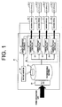
- the charging system has a charge controller 21 for controlling electric power supplied through a power distribution line, and four charging devices 22-1, 22-2, 22-3 and 22-4.
- the charge controller 21 has an AC to DC converter 23 for converting AC voltage supplied from a power switchboard connected to the AC power distribution line to DC voltage.
- the charge controller 21 further has a rechargeable battery 24, a current/vottage control unit 25, a battery monitor 26 for monitoring the voltage of the rechargeable battery 24 and a current distribution controller 27.
- the current/voltage control unit 25 serving as a current supply unit includes four current/voltage controllers 25-1, 25-2, 25-3 and 25-4 and controls to supply current from the rechargeable battery 24 to the respective charging devices 22-1, 22-2, 22-3 and 22-4.
- the battery monitor 26 monitors the charging amount of the rechargeable battery 24 and informs the current distribution controller 27 of the charging amount of the rechargeable battery 24.
- the current distribution controller 27 receives charging data of the charging amount of the rechargeable battery 24 from the battery monitor 26 and also receives charging data about electric vehicles or plug-in hybrid vehicles (EV/PHV, hereinafter referred to merely "vehicle") 28-1, 28-2, 28-3 and 28-4 from the charging devices 22-1, 22-2, 22-3 and 22-4. Based on the received data, the current distribution controller 27 determines distribution of currents from the current/vottage controllers 25-1, 25-2, 25-3 and 25-4 to the respective charging devices 22-1, 22-2, 22-3 and 22-4. Data communication between the current distribution controller 27 and the respective charging devices 22-1, 22-2, 22-3 and 22-4 is done through wire communication or wireless communication.
- Fig. 2 shows the current/voltage controllers 25-1 and its related devices.
- the current/voltage controller 25-1 has a voltage converter 31 for converting DC voltage to AC voltage or to any specific DC voltage and a current controller 32 for variably controlling the current.
- the current controller 32 controls current supplied to the charging device 22-1 based on a control signal from the current distribution controller 27.
- Fig. 3 showing a flowchart illustrating operation of the charge controller 21, it is determined at step S11 whether or not the vehicle 28-1, 28-2, 28-3 and 28-4 are connected to the charging devices 22-1, 22-2, 22-3 and 22-4, respectively.
- the determination at step 11 is conducted by using the charging data from the charging devices 22-1, 22-2, 22-3 and 22-4 indicating whether or not the vehicles 28-1, 28-2, 28-3 and 28-4 are connected to the charging devices 22-1, 22-2, 22-3 and 22-4, respectively.
- step S11 If NO at step S11, the rechargeable battery 24 is charged at step S12. If YES at step S11, it is determined at step S13 whether or not the amount of charge of the rechargeable battery 24 is sufficient. The determination at step 13 is conducted based on the monitoring data from the battery monitor 26.
- step S13 the rated current of the power distribution line is supplied to the respective charging devices 22-1, 22-2, 22-3 and 22-4, at step 14.
- step 15 the distribution of current from the rechargeable battery 24 to the respective charging devices 22-1, 22-2, 22-3 and 22-4 through the current/voltage controllers 25-1, 25-2, 25-3 and 25-4 is determined at step 15 based on the number of the vehicles 28-1, 28-2, 28-3 and 28-4 connected to the charging devices 22-1, 22-2, 22-3 and 22-4 and priorities of the vehicles to be charged. Specifically, the step 15 is performed to determine which vehicle should be charged preferentially, by using the charging data about the vehicle provided from the charging devices 22-1, 22-2, 22-3 and 22-4. Based on the result of the determination at step 15, distribution of current to the respective charging devices 22-1, 22-2, 22-3 and 22-4 from the current/voltage controllers 25-1, 25-2, 25-3 and 25-4 is determined.
- electric power supplied through the power distribution line is stored in the rechargeable battery 24, and the stored electric power in the rechargeable battery 24 is supplied to the respective charging devices 22-1, 22-2, 22-3 and 22-4, so that current greater than the rated current of the power distribution line may be supplied to the charging devices 22-1, 22-2, 22-3 and 22-4.
- the distribution of current may be appropriately determined based on the charging data from the charging devices 22-1, 22-2, 22-3 and 22-4. For example, current to be supplied to the charging device for a specific vehicle having the highest priority may be set to be greater than that to be supplied to the other charging devices, so that charging time for the vehicle of the highest priority may be shortened.
- the rechargeable battery 24 is charged during nighttime when electric power rate is relatively low, and the electric power stored in the rechargeable battery 24 is supplied to the charging devices 22-1, 22-2, 22-3 and 22-4 during daytime.
- a plurality of the secondary batteries such as 24 may be provided in the charging system, and the secondary batteries may be charged in turn. In this case, current several times as large as the rated current may be supplied to the vehicles.
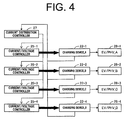
- Fig. 4 illustrates an example of the operation of the current distribution controller 27 and the current/voltage control unit 25 in such a case that a user of a charging device selects either normal charging mode by paying normal fee or quick charging mode by paying extra fee for using a priority service in charging his/her vehicle and the current distribution controller 27 determines the distribution of current to be supplied to the respective charging devices 22-1, 22-2, 22-3 and 22-4.
- Selection buttons for selecting normal or quick charging mode as a priority are provided in the charging devices 22-1, 22-2, 22-3 and 22-4, respectively. The user operates one of the selection buttons according to the charging mode.
- the charging devices 22-1, 22-2, 22-3 and 22-4 When the selection button is operated, the charging devices 22-1, 22-2, 22-3 and 22-4 generates to the current distribution controller 27 the charging data indicating the priority according to the operated selection button. For example, when a user of the charging device 22-1 operates the selection button for the quick charging by paying extra fee, the charging data indicating the quick charging is outputted from the charging device 22-1 to the current distribution controller 27. In this exemplary case, it is assumed that the charging devices 22-2, 22-3 and 22-4 are used for normal charging. Therefore, the charging devices 22-2, 22-3 and 22-4 output the charging data for the normal charging.
- the current distribution controller 27 receives from the charging device 22-1 the charging data indicating the quick charging for the charging device 22-1, and from the charging devices 22-2, 22-3 and 22-4 the charging data indicating the normal charging for the charging devices 22-2, 22-3 and 22-4. Accordingly, the current distribution controller 27 controls the operation of the current/voltage controller 25-1, 25-2, 25-3 and 25-4, as follows.
- the current distribution controller 27 commands the current/voltage controller 25-1 to supply to the charging device 22-1 current of 10 ampere that is twice as large as the normal current. Simultaneously, the current distribution controller 27 commands the other current/voltage controllers 25-2, 25-3 and 25-4 to supply current of 5 ampere to each of the charging devices 22-2, 22-3 and 22-4.
- the current distribution controller 27 receives the charging data indicating the priority from the charging devices 22-1, 22-2, 22-3 and 22-4 and controls the distribution of current being supplied from the rechargeable battery 24 to the charging devices 22-1, 22-2, 22-3 and 22-4 through the current/voltage controllers 25-1, 25-2, 25-3 and 25-4 based on the received charging data.
- current whose amperage is more than the rated current of the power distribution line may be supplied to the charging devices 22-1, 22-2, 22-3 and 22-4 by utilizing the rechargeable battery 24.
- the distribution of current is determined based on the charging data of the priority received from the charging devices 22-1, 22-2, 22-3 and 22-4, so that charging time may be shortened by increasing the amperage of the current supplied to a vehicle having the highest priority.
- current is distributed from the rechargeable battery 24 to a plurality of the charging devices 22-1, 22-2, 22-3 and 22-4 so that the current is shared by the charging devices 22-1,22-2,22-3 and 22-4.
- supplying of current from the rechargeable battery 24 to the respective charging devices 22-1, 22-2, 22-3 and 22-4 may be done separately so that charging may be performed for one vehicle at a time.
- the maximum current is supplied from the rechargeable battery 24 to the charging device 22-1 of the highest or first priority through the current/voyage controller 25-1 for a predetermined length of time. After an elapse of the predetermined time, the same maximum current is supplied from the rechargeable battery 24 then to a charging device of the second priority.
- current sharing may be used.
- the charge controller 21 may be arranged so as to permit a user of the charging device to input the charging data of his/her scheduled time of using the vehicle and also the remaining amount of electric power in the battery through the charging devices 22-1, 22-2, 22-3 and 22-4.
- the current distribution controller 27 receives the charging data from the charging devices 22-1, 22-2, 22-3 and 22-4 and determines the distribution of current from the current/voltage controllers 25-1, 25-2, 25-3 and 25-4 to the charging devices 22-1, 22-2, 22-3 and 22-4 based on the received charging data.
- a first user of the charging device 22-1 inputs the charging data of 6:00 am as the scheduled time of using the vehicle and 20 % as the remaining amount of electric power in the battery
- a second user of the charging device 22-2 inputs data of 2:00 pm and 80 %
- a third user of the charging device 22-3 inputs data of 8:00 AM and 50 %.
- the current distribution controller 27 determines the distribution of current supplied to the respective charging devices 22-1, 22-2, 22-3 and 22-4 so that the vehicle having the earliest scheduled time is charged preferentially.
- the distribution of current is determined such that the charging device for charging the vehicle having the earliest scheduled time has the highest priority to charge the vehicle.
- a charge controller supplies current to a plurality of charging devices for charging a battery for a vehicle including an electric vehicle and a plug-in hybrid vehicle.
- the charge controller includes a rechargeable battery, a current supply unit and a current distribution controller.
- the rechargeable battery stores electric power supplied from a power distribution line.
- the current supply unit supplies current from the rechargeable battery to the charging devices.
- the current distribution controller determines distribution of the current supplied through the current supply unit to the charging devices based on the charging data about the vehicle received from the charging devices.
Landscapes
- Engineering & Computer Science (AREA)
- Power Engineering (AREA)
- Transportation (AREA)
- Mechanical Engineering (AREA)
- Life Sciences & Earth Sciences (AREA)
- Sustainable Development (AREA)
- Sustainable Energy (AREA)
- Charge And Discharge Circuits For Batteries Or The Like (AREA)
- Electric Propulsion And Braking For Vehicles (AREA)
- Remote Monitoring And Control Of Power-Distribution Networks (AREA)
- Secondary Cells (AREA)
Applications Claiming Priority (1)
| Application Number | Priority Date | Filing Date | Title |
|---|---|---|---|
| JP2010134646A JP5533306B2 (ja) | 2010-06-14 | 2010-06-14 | 充電制御装置及びその充電制御方法 |
Publications (2)
| Publication Number | Publication Date |
|---|---|
| EP2399772A2 true EP2399772A2 (de) | 2011-12-28 |
| EP2399772A3 EP2399772A3 (de) | 2014-11-05 |
Family
ID=44720450
Family Applications (1)
| Application Number | Title | Priority Date | Filing Date |
|---|---|---|---|
| EP11169417.0A Withdrawn EP2399772A3 (de) | 2010-06-14 | 2011-06-10 | Ladungssteuerung und Betriebsverfahren dafür |
Country Status (5)
| Country | Link |
|---|---|
| US (1) | US20110304304A1 (de) |
| EP (1) | EP2399772A3 (de) |
| JP (1) | JP5533306B2 (de) |
| KR (1) | KR20110136721A (de) |
| CN (1) | CN102280918A (de) |
Cited By (2)
| Publication number | Priority date | Publication date | Assignee | Title |
|---|---|---|---|---|
| WO2014184729A3 (en) * | 2013-05-17 | 2015-04-30 | Institute For Energy Application Technologies Co.,Ltd. | Rapid charging power supply system |
| US9555715B2 (en) | 2011-12-08 | 2017-01-31 | Institute For Energy Application Technologies Co., Ltd. | Rapid charging power supply system |
Families Citing this family (14)
| Publication number | Priority date | Publication date | Assignee | Title |
|---|---|---|---|---|
| US9148027B2 (en) | 2012-07-30 | 2015-09-29 | General Electric Company | Method and system for charging of electric vehicles |
| KR101924234B1 (ko) * | 2012-09-06 | 2018-11-30 | 한국전력공사 | 3상 전기차 교류 충전 장치 및 방법 |
| CN105094187B (zh) * | 2014-05-07 | 2017-04-19 | 湖南汇德电子有限公司 | 电流转换方法和装置 |
| WO2016107604A1 (zh) * | 2014-12-31 | 2016-07-07 | 北京国创富盛通信股份有限公司 | 充电设备和充电方法 |
| CN105990883B (zh) * | 2015-02-05 | 2018-09-25 | 深圳市瀚美特科技有限公司 | 一种多枪头大功率直流充电桩系统 |
| KR102248347B1 (ko) * | 2017-05-09 | 2021-05-06 | 고도가이샤 츄라에코넷토 | 태양광 발전 설비 |
| JP7003595B2 (ja) * | 2017-11-21 | 2022-01-20 | トヨタ自動車株式会社 | 賃貸料金設定装置、賃貸料金設定方法および賃貸料金設定システム |
| US10723239B2 (en) * | 2018-06-29 | 2020-07-28 | Ford Global Technologies, Llc | Multi-outlet vehicle charge device and control strategy |
| WO2020150155A1 (en) * | 2019-01-14 | 2020-07-23 | Cummins Inc. | Systems, apparatuses, and methods for charging multiple vehicles in close proximity |
| CA3074829A1 (en) * | 2019-03-15 | 2020-09-15 | Proterra Inc. | Charging system for electric vehicles |
| DE102020205885A1 (de) | 2020-02-26 | 2021-08-26 | Siemens Aktiengesellschaft | Elektrische Ladeinfrastruktur für mobile Energiespeicher und Verfahren zum Betreiben einer elektrischen Ladeinfrastruktur |
| DE102020209653A1 (de) * | 2020-07-30 | 2022-02-03 | Volkswagen Aktiengesellschaft | Elektrisches Ladesystem zum Laden eines elektrischen Akkumulators |
| US20230011000A1 (en) * | 2021-07-08 | 2023-01-12 | Enersys Delaware Inc. | Direct current fast charging systems with grid tied energy storage systems |
| JP7790269B2 (ja) * | 2022-05-09 | 2025-12-23 | 株式会社豊田自動織機 | 充電器 |
Citations (2)
| Publication number | Priority date | Publication date | Assignee | Title |
|---|---|---|---|---|
| JPH05316606A (ja) | 1992-05-13 | 1993-11-26 | Yamaha Motor Co Ltd | 電動車両用充電システム |
| JP2003204625A (ja) | 2001-10-17 | 2003-07-18 | Kansai Electric Power Co Inc:The | 電力安定供給装置 |
Family Cites Families (22)
| Publication number | Priority date | Publication date | Assignee | Title |
|---|---|---|---|---|
| JP3211323B2 (ja) * | 1992-01-24 | 2001-09-25 | 株式会社明電舎 | 充電装置 |
| US5548200A (en) * | 1994-07-06 | 1996-08-20 | Norvik Traction Inc. | Universal charging station and method for charging electric vehicle batteries |
| JPH08116626A (ja) * | 1994-10-17 | 1996-05-07 | Nissan Motor Co Ltd | 充電システム |
| US5594318A (en) * | 1995-04-10 | 1997-01-14 | Norvik Traction Inc. | Traction battery charging with inductive coupling |
| US5635773A (en) * | 1995-08-23 | 1997-06-03 | Litton Systems, Inc. | High efficiency, no dropout uninterruptable power supply |
| US7256516B2 (en) * | 2000-06-14 | 2007-08-14 | Aerovironment Inc. | Battery charging system and method |
| JP2002271992A (ja) * | 2001-03-14 | 2002-09-20 | Internatl Business Mach Corp <Ibm> | 電力供給装置、電力供給方法、電気機器および電気機器における電力供給方法 |
| US20040201365A1 (en) * | 2001-04-05 | 2004-10-14 | Electrovaya Inc. | Energy storage device for loads having variable power rates |
| JP3690665B2 (ja) * | 2001-10-30 | 2005-08-31 | インターナショナル・ビジネス・マシーンズ・コーポレーション | 電気機器、コンピュータ装置、および電力供給方法 |
| US6963186B2 (en) * | 2003-02-28 | 2005-11-08 | Raymond Hobbs | Battery charger and method of charging a battery |
| CN101150259B (zh) * | 2006-09-18 | 2010-05-12 | 比亚迪股份有限公司 | 电动车充电系统 |
| US8736224B2 (en) * | 2007-03-09 | 2014-05-27 | Ford Global Technologies, Llc | Charging a battery using a circuit having shared loads |
| US8054048B2 (en) * | 2007-10-04 | 2011-11-08 | GM Global Technology Operations LLC | Power grid load management for plug-in vehicles |
| JP4333798B2 (ja) * | 2007-11-30 | 2009-09-16 | トヨタ自動車株式会社 | 充電制御装置および充電制御方法 |
| US8872379B2 (en) * | 2007-11-30 | 2014-10-28 | Johnson Controls Technology Company | Efficient usage, storage, and sharing of energy in buildings, vehicles, and equipment |
| CN101640427B (zh) * | 2008-08-01 | 2012-10-24 | 新奥科技发展有限公司 | 电动车光伏离网充电系统 |
| JP5081780B2 (ja) * | 2008-09-30 | 2012-11-28 | 本田技研工業株式会社 | 電動車両用充電制御装置 |
| US8138630B2 (en) * | 2009-09-22 | 2012-03-20 | Ebay Inc. | Solar powered system with grid backup |
| US20110082598A1 (en) * | 2009-10-02 | 2011-04-07 | Tod Boretto | Electrical Power Time Shifting |
| JPWO2011118187A1 (ja) * | 2010-03-23 | 2013-07-04 | パナソニック株式会社 | 充電制御装置、充電システムおよび充電制御方法 |
| US8478452B2 (en) * | 2010-04-06 | 2013-07-02 | Battelle Memorial Institute | Grid regulation services for energy storage devices based on grid frequency |
| JP5647057B2 (ja) * | 2010-05-19 | 2014-12-24 | 株式会社日立製作所 | 充電装置、充電制御ユニット及び充電制御方法 |
-
2010
- 2010-06-14 JP JP2010134646A patent/JP5533306B2/ja not_active Expired - Fee Related
-
2011
- 2011-06-10 EP EP11169417.0A patent/EP2399772A3/de not_active Withdrawn
- 2011-06-10 CN CN201110163272XA patent/CN102280918A/zh active Pending
- 2011-06-10 US US13/157,354 patent/US20110304304A1/en not_active Abandoned
- 2011-06-13 KR KR1020110056736A patent/KR20110136721A/ko not_active Ceased
Patent Citations (2)
| Publication number | Priority date | Publication date | Assignee | Title |
|---|---|---|---|---|
| JPH05316606A (ja) | 1992-05-13 | 1993-11-26 | Yamaha Motor Co Ltd | 電動車両用充電システム |
| JP2003204625A (ja) | 2001-10-17 | 2003-07-18 | Kansai Electric Power Co Inc:The | 電力安定供給装置 |
Cited By (2)
| Publication number | Priority date | Publication date | Assignee | Title |
|---|---|---|---|---|
| US9555715B2 (en) | 2011-12-08 | 2017-01-31 | Institute For Energy Application Technologies Co., Ltd. | Rapid charging power supply system |
| WO2014184729A3 (en) * | 2013-05-17 | 2015-04-30 | Institute For Energy Application Technologies Co.,Ltd. | Rapid charging power supply system |
Also Published As
| Publication number | Publication date |
|---|---|
| JP2012005154A (ja) | 2012-01-05 |
| JP5533306B2 (ja) | 2014-06-25 |
| KR20110136721A (ko) | 2011-12-21 |
| EP2399772A3 (de) | 2014-11-05 |
| CN102280918A (zh) | 2011-12-14 |
| US20110304304A1 (en) | 2011-12-15 |
Similar Documents
| Publication | Publication Date | Title |
|---|---|---|
| EP2399772A2 (de) | Ladungssteuerung und Betriebsverfahren dafür | |
| JP5479597B2 (ja) | ジャンプスタート方法、およびジャンプスタート方法を実施するための装置 | |
| EP2683048B1 (de) | Ladestromsteuerungssystem | |
| US9421867B2 (en) | Electric vehicle | |
| EP2535218A1 (de) | Stromversorgungssystem für elektrofahrzeug und steuerverfahren dafür | |
| EP3029804A1 (de) | Ladestation und energieverwaltungsverfahren für ladestation | |
| US9493081B2 (en) | Power supply system, vehicle equipped with the same, and control method for power supply system | |
| CN109906169B (zh) | 用于双电压电池的运行方法 | |
| JP2011239559A (ja) | 電気自動車の充電装置 | |
| US10343539B2 (en) | Power supply device for supplying electricity to a load utilizing electric power of a storage-battery-equipped vehicle | |
| EP2437367A2 (de) | Lastkoordinierender Leistungszug für Schaltungen mit eingeschränkter Belastbarkeit | |
| JP2013090525A (ja) | 電力貯蔵装置、電源装置、電動車両、移動体、及び制御装置 | |
| US9469210B2 (en) | Vehicle | |
| JP2013110912A (ja) | 蓄電システム及び蓄電システムを搭載した車両の制御装置 | |
| US20230234467A1 (en) | Control apparatus | |
| JP7185750B2 (ja) | 充放電装置、充放電システムおよび充放電制御方法 | |
| JP2012075268A (ja) | 蓄電池の充電システム | |
| US20230234476A1 (en) | Control apparatus | |
| JP7253952B2 (ja) | 車両 | |
| JP2023153480A (ja) | 情報機器 | |
| JP2021176254A (ja) | 充電装置 | |
| CN114825501B (zh) | 电力供给系统及电力供给方法 | |
| JP2023104309A (ja) | 充放電装置および充放電システム | |
| JP2017158225A (ja) | 電力制御装置 | |
| JP2025071541A (ja) | 交換式電池パックの利用可否判定装置 |
Legal Events
| Date | Code | Title | Description |
|---|---|---|---|
| 17P | Request for examination filed |
Effective date: 20110610 |
|
| AK | Designated contracting states |
Kind code of ref document: A2 Designated state(s): AL AT BE BG CH CY CZ DE DK EE ES FI FR GB GR HR HU IE IS IT LI LT LU LV MC MK MT NL NO PL PT RO RS SE SI SK SM TR |
|
| AX | Request for extension of the european patent |
Extension state: BA ME |
|
| PUAI | Public reference made under article 153(3) epc to a published international application that has entered the european phase |
Free format text: ORIGINAL CODE: 0009012 |
|
| PUAL | Search report despatched |
Free format text: ORIGINAL CODE: 0009013 |
|
| AK | Designated contracting states |
Kind code of ref document: A3 Designated state(s): AL AT BE BG CH CY CZ DE DK EE ES FI FR GB GR HR HU IE IS IT LI LT LU LV MC MK MT NL NO PL PT RO RS SE SI SK SM TR |
|
| AX | Request for extension of the european patent |
Extension state: BA ME |
|
| RIC1 | Information provided on ipc code assigned before grant |
Ipc: B60L 11/18 20060101AFI20141001BHEP Ipc: H02J 7/00 20060101ALI20141001BHEP |
|
| STAA | Information on the status of an ep patent application or granted ep patent |
Free format text: STATUS: THE APPLICATION IS DEEMED TO BE WITHDRAWN |
|
| 18D | Application deemed to be withdrawn |
Effective date: 20150507 |