EP2399531B1 - Bohreinsatz - Google Patents
Bohreinsatz Download PDFInfo
- Publication number
- EP2399531B1 EP2399531B1 EP11182409.0A EP11182409A EP2399531B1 EP 2399531 B1 EP2399531 B1 EP 2399531B1 EP 11182409 A EP11182409 A EP 11182409A EP 2399531 B1 EP2399531 B1 EP 2399531B1
- Authority
- EP
- European Patent Office
- Prior art keywords
- drill bit
- face
- faces
- drill
- bit according
- Prior art date
- Legal status (The legal status is an assumption and is not a legal conclusion. Google has not performed a legal analysis and makes no representation as to the accuracy of the status listed.)
- Expired - Lifetime
Links
Images


Classifications
-
- A—HUMAN NECESSITIES
- A61—MEDICAL OR VETERINARY SCIENCE; HYGIENE
- A61B—DIAGNOSIS; SURGERY; IDENTIFICATION
- A61B17/00—Surgical instruments, devices or methods, e.g. tourniquets
- A61B17/16—Bone cutting, breaking or removal means other than saws, e.g. Osteoclasts; Drills or chisels for bones; Trepans
- A61B17/1613—Component parts
- A61B17/1615—Drill bits, i.e. rotating tools extending from a handpiece to contact the worked material
-
- B—PERFORMING OPERATIONS; TRANSPORTING
- B23—MACHINE TOOLS; METAL-WORKING NOT OTHERWISE PROVIDED FOR
- B23B—TURNING; BORING
- B23B51/00—Tools for drilling machines
-
- B—PERFORMING OPERATIONS; TRANSPORTING
- B23—MACHINE TOOLS; METAL-WORKING NOT OTHERWISE PROVIDED FOR
- B23B—TURNING; BORING
- B23B51/00—Tools for drilling machines
- B23B51/02—Twist drills
-
- Y—GENERAL TAGGING OF NEW TECHNOLOGICAL DEVELOPMENTS; GENERAL TAGGING OF CROSS-SECTIONAL TECHNOLOGIES SPANNING OVER SEVERAL SECTIONS OF THE IPC; TECHNICAL SUBJECTS COVERED BY FORMER USPC CROSS-REFERENCE ART COLLECTIONS [XRACs] AND DIGESTS
- Y10—TECHNICAL SUBJECTS COVERED BY FORMER USPC
- Y10T—TECHNICAL SUBJECTS COVERED BY FORMER US CLASSIFICATION
- Y10T408/00—Cutting by use of rotating axially moving tool
- Y10T408/89—Tool or Tool with support
- Y10T408/907—Tool or Tool with support including detailed shank
Definitions
- the present invention relates to a drill bit to drilling bones, cartilage and similar structures during orthopaedic surgery.
- the drill tip can quickly create a securing hole which secures the drill bit in position so as to prevent the drill bit from moving over the surface of the material when starting to drill.
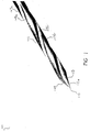
- Figure 1 shows, a first drill bit 101.
- the drill bit 101 includes a shaft 103 which has a pyramidal shaped end 105 defining a drill tip.
- the material from which the drill bit 101 is made depends on the intended application of the drill bit 101. However, for orthopaedic surgery, the drill bit 101 is made from surgical quality stainless steel.
- the other end of the drill bit 101 is adapted for mounting in a motorized drill chuck.
- the other end of the drill bit 101 can be provided with a series of graduations, a cut-away and a circumferential groove in the shaft 103 adjacent the other end so as to facilitate its coupling in the chuck of a drive of a motorised surgical drill.
- the graduations can be used to indicate depth of insertion of the drill bit into the drive chuck and into the patient.
- the drill bit 101 also includes one or more recesses in the form of grooves 107, each of which includes a first portion 109 extending at least partway along the shaft 103 and a second portion 111 which extends along an edge 113 of the drill tip.
- edge 113 defines a cutting edge.
- the edge 113 also includes bevelling so as to enhance the cutting ability of the cutting edge.
- the grooves 107 allow debris which is produced whilst drilling to be channeled away from the hole while being drilled.
- the first portion 109 of each of the grooves 107 spirals along the shaft 103 so as to form of a helix, whilst the second portion 111 is substantially straight (that is, tending to align with a longitudinal axis of the shaft).
- Each of the grooves 107 typically has an arcuate semi-cylindrical shape in cross-section and along its length. However, other suitable profiles such a V-shape or square shape may be employed.
- the depth of the second portion 111 of each of the grooves 107 varies along the length of the second portion 111 relative to the surface of the drill tip in which the second portion 111 is located. More specifically, the depth of the second portion 111 of each of the grooves 107 becomes shallower towards the point 115 of the drill bit 101. This provides the cutting edge located nearer the point 115 with a lesser cutting ability than the portion of the cutting edge 119 located nearer the shaft. The advantage of this is that the drill tip is less likely to break as a result of locking with the material into which the drill bit 101 is entering.
- the pyramidal shaped end 105 is formed from three elongate surfaces, but more surfaces can be employed if desired. Increasing the number of surfaces to define the pyramidal shaped end 105 results in more edges 113 which can define more cutting edges.
- the pyramidal shaped end 105 is relatively longer than the drill tip of existing drills. This provides an extreme point 115 which assists in securely locating the drill bit 101 so as to prevent movement thereof when drilling is started. The assistance is provided as a result of the extreme point 115 piercing the periosteum and puncturing the outer surface of the bone, thereby locating the drill bit 101 in place prior to drilling.
- Each of the surfaces forming the pyramidal shaped end 105 subtends an angle with the longitudinal axis of the drill bit 101. The angle is typically around 30°, but may be varied depending on the application (for example, hardness of the material to be drilled).
- the drill bit 101 is made from a material that is suitable for the intended application.
- the drill bit 101 is made from surgical quality stainless steel.
- the drill bit 101 is made from a blank rod of the appropriate material. Using a suitable grinder, one of the ends of the blank rod can be ground down so as to form the pyramidal shaped end 105 and adapt the other end of the drill bit 101 so that the drill bit 101 can be retained by a chuck of a drill.
- the grinding machine can also be used to form the grooves 107.
- the grinding wheel of the machine remains fixed so that the first portion 109 has a constant depth.
- the grinding wheel is gradually moved outwardly from the drill tip as it moves towards the point 115. Moving the grinding wheel outwardly results in the second portion 111 having a depth that varies along the length of the drill tip. This characteristic produces a cutting edge which has a lesser cutting ability about the point 115 and which increases in cutting ability towards the shaft 103. Having a lesser cutting ability at the point 115 reduces the likelihood of the point 115 breaking off when drilling is commenced due to the cutting edge locking with the material into which the hole is being drilled.
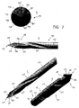
- the drill bit 310 includes a drill shaft 312, the opposite end 313 of which is adapted for mounting in a motorised drill chuck.
- the opposite end of the shaft can be provided with a series of gradations 314, a cut-away 315 and a circumferential groove 316 adjacent to end 313 to facilitate its coupling in the chuck of a drive of a motorised surgical drill.
- the gradations can be used to indicate depth of insertion of the drill bit in both the drive chuck and into a patient.
- a plurality of spiral flutes 317 extend from near the drilling end 318 and part way along the shaft 312.
- Each flute is typically an arcuate semi-cylindrical groove extending in the shaft, but may be v-shaped, square shaped etc. in cross-section.
- Each flute provides a passageway for the release of debris cut by the drill bit as it is inserted through a substrate (typically a bone).
- a substrate typically a bone.
- two or three such spiral flutes are provided in the drill bit to maximise debris release.
- a drill point 319 is provided at drilling end 318, the drill point being substantially elongated, tapered and pointed when compared with a conventional drill bit.
- the drill point is provided as a trocar-type formation.
- one or more, and typically three, bevelled faces 320 are provided and combine to define the drill point 319 at drilling end 316, each face subtending an angle ⁇ with a longitudinal axis A ⁇ through the shaft 312.
- the subtended angle ⁇ is around 30°, although it may be varied depending on the application (e.g. hardness of material to be drilled).
- the three faces generally provide end 318 with a triangular pyramidal appearance.
- bevelled faces 320 define cutting edges 322 along the side of each bevelled face which facilitate cutting and thus drilling into a bone or similar when the drill bit is rotated.
- an extreme drill point 319 at drilling end 318 also enables the drill to be securingly located at a bone, piercing the periosteum and puncturing the outer surface of the bone to locate the drill bit in place prior to drilling.
- each flute 317 intersects with a respective face 320 at a location that is offset from a centre line CL through the face 320.
- the advantage of this offsetting is that it facilitates maximum debris removal during cutting of bone, cartilage and other bodily material.
- uppermost face 320' defines a leading edge 322' and a trailing edge 322". It will be see that flute 317' is located adjacent to the trailing edge.
- This maximal face area prevents bunching or blocking of debris at the face and enhances debris release away from the drill point. Therefore, an optimal location for the intersection of each flute with its respective face is adjacent to the trailing edge for that face, as shown in Figure 3A .
- rapid debris removal also facilitates more rapid drilling.
- drilling end 518 is now provided with four bevelled faces 520 (which in this drill bit are typically flat faces).
- the four faces generally provide end 518 with a square pyramidal appearance.
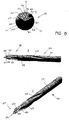
- a surgical drill bit having three faces at drilling end 618, similar to the drill bit of Figures 3 and 4 , is shown.
- Each face also has a respective flute intersecting therewith, however, in this drill bit the intersection between the flute and its respective face is not abrupt but is gradual as facilitated by a continuous curved region 626.
- This region provides a kind of scalloping or concavity in each face 620, thus enhancing the definition of the drill point 619, but also providing a more pronounced channelling affect into each flute to guide and enhance the removal of debris cut by the rotating drill bit.
- the more pronounced drill point facilitates easier drill bit location at slippery cutting surfaces and easier penetration.
- the region 626 facilitates more rapid removal of debris and thus even faster drill cutting.
- each face 720 is concaved inwardly with respect to the drill bit, defining an arcuate 3D scalloped surface. This is best seen with reference to Figure 7D .
- the drill bit of Figure 7 also employs the continuous curved region 726 at the intersection of flute 717 and face 720 so that debris cut by the drilling end is rapidly conveyed away therefrom in use.
- the concave face in end view (i.e. Figure 7A ) is typically symmetrical about face centre line CL.
- the concave face can be defined asymmetrically about the centre line, for example, so that adjacent to the leading edge 722', the face slopes more steeply away, and slopes more gradually up towards the trailing edge 722".
- This asymmetric offset of the concavity at each face can sharpen the leading edge relative to the trailing edge and can enhance debris being directed towards flute 717 (i.e. by pressure differentials etc.).
- the operation of the drill bit of Figure 7 is in other respects similar to that previously described.
- FIG. 8 the inwardly concave curved face of Figure 7 is replaced by two flat sub-faces 827 and 828.
- the sub-faces 827 and 828 in end view define face 820 as a type of tapering v-shaped groove (i.e. tapering down to drill point 819).
- face 820 as a type of tapering v-shaped groove (i.e. tapering down to drill point 819).
- the employment of a concave v-shaped face 820 sharpens or pronounces the edges 822, and also assists in directing debris towards flute 817 via curved region 826.
- sub-faces 827 and 828 are arranged symmetrically about face centre line CL, but may be asymmetrically offset to e.g. more steeply slope away from the leading edge 822' as opposed to the trailing edge 822". Again, this can define a sharper cutting edge and assist with the distribution of debris away from the drilling end 818.
- a drill bit having either flat faces 920 as shown in Figure 6 , or curved faces as shown in Figure 7 is depicted.
- a chamfer 930 is provided that slopes away from the leading edge 922 and into its respective face as best shown in Figure 9A .
- a small section 931 of chamfer 930 continues on and extends partway up trailing edge 922", so that drill point 919 is defined by the merging of three chamfered faces and thus is unitary and pyramidal in shape (i.e. trocar-like).
- the drill bit of Figure 9 is similar in construction to the drill bit of Figures 6 and 7 and operates in a similar manner to the drill bits previously described.
- FIG. 10A to 10C where like reference numerals are used to denote similar or like parts, a further modified drill bit is shown.
- the faces 1020 are typically flat (although may be slightly concave) in a similar manner to Figure 3 .
- no continuous curve region at the intersection of flute 1017 and face 1020 is depicted, although such a region may be provided as appropriate.
- a v-shaped groove 1032 running along the trailing edge 1022", from the drill point 1019 to the flute 1017.
- the v-shaped groove 1032 terminates in the flute 1017 and provides a further means for the channelling and directing of debris into the flute. In addition, it sharpens the leading edge 1022' of each face 1020, thus enhancing cutting. It also provides for the release of debris entrained in front of the leading edge as the drill bit rotates.
- the v-shaped groove 1032 can be symmetric or asymmetric as described above, with the advantages as described above.
- the flutes, faces and grooves are machined onto the shaft 1012, and typically the shaft 1012 is formed from surgical stainless steel.
- the shaft is typically cylindrical and circular in cross-section, although other cross-sectional shapes (e.g. hexagonal or octagonal) may be employed.
Claims (10)
- Orthopädischer Bohreinsatz (1010) zum Bohren von Knochen, umfassend:einen Schaft (1012) mit einem Bohrende, wobei das Bohrende Folgendes aufweist:(1) einen Bohrendpunkt (1019);
wobei der Schaft (1012) ferner zumindest eine Auskehlung (1017) aufweist, die in dem Schaft definiert ist, um beim Bohren erzeugte Trümmer abzuleiten; dadurch gekennzeichnet, dass das Bohrende ferner Folgendes aufweist:(2) einen distalen Abschnitt mit mindestens drei Flächen (1020), die sich an einem gemeinsamen Punkt treffen, um den Bohrendpunkt (1019), angeordnet auf der Längsachse des Schafts (1012), zu definieren, wobei die drei Flächen (1020) pyramidenförmig angeordnet sind, wobei die drei Flächen (1020) drei Schneidkanten definieren, so dass jede Fläche eine vordere Schneidkante (1022') und eine hintere Schneidkante (1022") präsentiert; und(3) einen proximalen Abschnitt, der sich von dem distalen Abschnitt weg erstreckt, wobei sich ein Teil von zumindest einer Fläche der drei Flächen entlang des proximalen Abschnitts erstreckt, um einen kontinuierlichen Abschnitt der Fläche zu bilden;wobei der Schaft (1012) ferner eine V-förmige Nut (1032) aufweist, die zwischen dem Bohrendpunkt und der Auskehlung angeordnet ist, wobei die V-förmige Nut (1032) entlang einer hinteren Kante (1022") von zumindest einer Fläche der drei Flächen verläuft, wobei die hintere Kante (1022") zumindest entlang des kontinuierlichen Abschnitts der Fläche angeordnet ist, wobei die V-förmige Nut (1032) in der Auskehlung (1017) endet und ausgelegt ist, Trümmer in die Auskehlung (1017) zu lenken und zu leiten. - Bohreinsatz nach Anspruch 1, worin die V-förmige Nut (1032) eine vordere Kante (1022') der zumindest einen Fläche oder der drei Flächen (1020) schärft, wodurch die Einführung des Bohrendpunkts entlang der Längsachse und in die Oberfläche des zu bohrenden Knochenmaterials verbessert ist, worin die vordere Kante zumindest entlang des kontinuierlichen Abschnitts der Fläche angeordnet ist.
- Bohreinsatz nach Anspruch 1, worin die drei Flächen (1020) alle im Wesentlichen flach sind.
- Bohreinsatz nach Anspruch 1, worin die drei Flächen (1020) konkav gebogen sind.
- Bohreinsatz nach Anspruch 1 bis 4, worin der proximale Abschnitt einen kontinuierlichen Abschnitt einer anderen Fläche der drei Flächen (1020) aufweist, und worin der kontinuierliche Abschnitt der anderen Fläche einen kontinuierlichen Abschnitt der Schneidkante aufweist.
- Bohreinsatz nach Anspruch 5, worin die Auskehlung (1017) den kontinuierlichen Abschnitt der einen Fläche schneidet.
- Bohreinsatz nach Anspruch 6, worin die V-förmige Nut (1032) zwischen dem kontinuierlichen Abschnitt der einen Fläche (1020) und dem kontinuierlichen Abschnitt der anderen Fläche (1020) angeordnet ist, und sich entlang des kontinuierlichen Abschnitts der Schneidkante der anderen Fläche erstreckt, wodurch die Schärfe der Schneidkante der anderen Fläche (1020) beeinflusst wird.
- Bohreinsatz nach Anspruch 1 bis 7, worin jede der Flächen (1020) bezüglich der anderen zwei Flächen gleichmäßig versetzt ist.
- Bohreinsatz nach Anspruch 7, worin der Schaft zwei zusätzliche Auskehlungen (1017) aufweist.
- Bohreinsatz nach einem der vorhergehenden Ansprüche, worin der Bohrendpunkt (1019) einheitlich und pyramidenförmig geformt ist.
Applications Claiming Priority (3)
| Application Number | Priority Date | Filing Date | Title |
|---|---|---|---|
| AU2002950673A AU2002950673A0 (en) | 2002-08-08 | 2002-08-08 | Surgical drill bit |
| AU2002953610A AU2002953610A0 (en) | 2002-11-08 | 2002-11-08 | Surgical drill bit |
| EP03783839.8A EP1528892B1 (de) | 2002-08-08 | 2003-08-07 | Ein bohrmeissel und verfahren zur herstellung eines bohrmeissels |
Related Parent Applications (3)
| Application Number | Title | Priority Date | Filing Date |
|---|---|---|---|
| EP03783839.8A Division EP1528892B1 (de) | 2002-08-08 | 2003-08-07 | Ein bohrmeissel und verfahren zur herstellung eines bohrmeissels |
| EP03783839.8A Division-Into EP1528892B1 (de) | 2002-08-08 | 2003-08-07 | Ein bohrmeissel und verfahren zur herstellung eines bohrmeissels |
| EP03783839.8 Division | 2003-08-07 |
Publications (2)
| Publication Number | Publication Date |
|---|---|
| EP2399531A1 EP2399531A1 (de) | 2011-12-28 |
| EP2399531B1 true EP2399531B1 (de) | 2016-01-27 |
Family
ID=31716324
Family Applications (3)
| Application Number | Title | Priority Date | Filing Date |
|---|---|---|---|
| EP11182408.2A Expired - Lifetime EP2399530B1 (de) | 2002-08-08 | 2003-08-07 | Bohreinsatz |
| EP11182409.0A Expired - Lifetime EP2399531B1 (de) | 2002-08-08 | 2003-08-07 | Bohreinsatz |
| EP03783839.8A Expired - Lifetime EP1528892B1 (de) | 2002-08-08 | 2003-08-07 | Ein bohrmeissel und verfahren zur herstellung eines bohrmeissels |
Family Applications Before (1)
| Application Number | Title | Priority Date | Filing Date |
|---|---|---|---|
| EP11182408.2A Expired - Lifetime EP2399530B1 (de) | 2002-08-08 | 2003-08-07 | Bohreinsatz |
Family Applications After (1)
| Application Number | Title | Priority Date | Filing Date |
|---|---|---|---|
| EP03783839.8A Expired - Lifetime EP1528892B1 (de) | 2002-08-08 | 2003-08-07 | Ein bohrmeissel und verfahren zur herstellung eines bohrmeissels |
Country Status (9)
| Country | Link |
|---|---|
| US (8) | US7892235B2 (de) |
| EP (3) | EP2399530B1 (de) |
| JP (4) | JP5273896B2 (de) |
| CN (1) | CN100528093C (de) |
| AU (2) | AU2003250578B2 (de) |
| CA (3) | CA2857354C (de) |
| HK (2) | HK1165686A1 (de) |
| NZ (1) | NZ537852A (de) |
| WO (1) | WO2004014241A1 (de) |
Families Citing this family (56)
| Publication number | Priority date | Publication date | Assignee | Title |
|---|---|---|---|---|
| CA2857354C (en) * | 2002-08-08 | 2015-11-03 | Liam Patrick Ellis | A drill bit and method for producing a drill bit |
| US8361067B2 (en) | 2002-09-30 | 2013-01-29 | Relievant Medsystems, Inc. | Methods of therapeutically heating a vertebral body to treat back pain |
| DE602004024588D1 (de) * | 2004-02-05 | 2010-01-21 | Bti I & D | Geräte zur extraktion und sammlung von gewebepartikeln bei kühlungsloser bohrmethode mit niedriger drehgeschwindigkeit |
| US10028753B2 (en) | 2008-09-26 | 2018-07-24 | Relievant Medsystems, Inc. | Spine treatment kits |
| US8697874B2 (en) | 2008-12-01 | 2014-04-15 | Takeda Pharmaceutical Company Limited | Heterocyclic compound and use thereof |
| US8226654B2 (en) | 2008-12-04 | 2012-07-24 | Aeton Medical Llc | Trocar-tipped drill bit |
| US8366719B2 (en) | 2009-03-18 | 2013-02-05 | Integrated Spinal Concepts, Inc. | Image-guided minimal-step placement of screw into bone |
| CA2712796A1 (en) * | 2009-08-06 | 2011-02-06 | Textron Innovations Inc. | Hole saw with tapered pilot bit |
| CA2713309C (en) | 2009-08-20 | 2013-07-02 | Howmedica Osteonics Corp. | Flexible acl instrumentation, kit and method |
| US20130006248A1 (en) * | 2010-03-19 | 2013-01-03 | CPL Holdings Pty. Ltd. | Drill bit |
| EP2561822A4 (de) * | 2010-04-22 | 2014-11-05 | Neobiotech Co Ltd | Bohrmeissel und bohrer damit |
| BR112013012595A2 (pt) * | 2010-11-26 | 2017-07-11 | Cpl Holdings Pty Ltd | broca de perfuração |
| EP2672902B1 (de) * | 2011-02-11 | 2015-11-25 | CPL Holdings Pty Ltd | Bohrmeissel |
| US9795398B2 (en) | 2011-04-13 | 2017-10-24 | Howmedica Osteonics Corp. | Flexible ACL instrumentation, kit and method |
| US9445803B2 (en) | 2011-11-23 | 2016-09-20 | Howmedica Osteonics Corp. | Filamentary suture anchor |
| WO2013101772A1 (en) | 2011-12-30 | 2013-07-04 | Relievant Medsystems, Inc. | Systems and methods for treating back pain |
| US9808242B2 (en) | 2012-04-06 | 2017-11-07 | Howmedica Osteonics Corp. | Knotless filament anchor for soft tissue repair |
| US9232952B2 (en) | 2012-04-16 | 2016-01-12 | Medtronic Ps Medical, Inc. | Surgical bur with non-paired flutes |
| GB201209772D0 (en) | 2012-06-01 | 2012-07-18 | Renishaw Plc | Cranial drill system |
| WO2014015154A1 (en) | 2012-07-18 | 2014-01-23 | Milwaukee Electric Tool Corporation | Hole saw |
| US8821494B2 (en) | 2012-08-03 | 2014-09-02 | Howmedica Osteonics Corp. | Surgical instruments and methods of use |
| US10588691B2 (en) | 2012-09-12 | 2020-03-17 | Relievant Medsystems, Inc. | Radiofrequency ablation of tissue within a vertebral body |
| WO2014071161A1 (en) | 2012-11-05 | 2014-05-08 | Relievant Medsystems, Inc. | System and methods for creating curved paths through bone and modulating nerves within the bone |
| US9078740B2 (en) | 2013-01-21 | 2015-07-14 | Howmedica Osteonics Corp. | Instrumentation and method for positioning and securing a graft |
| US9402620B2 (en) | 2013-03-04 | 2016-08-02 | Howmedica Osteonics Corp. | Knotless filamentary fixation devices, assemblies and systems and methods of assembly and use |
| WO2014176270A1 (en) | 2013-04-22 | 2014-10-30 | Pivot Medical, Inc. | Method and apparatus for attaching tissue to bone |
| TWM464145U (zh) * | 2013-06-18 | 2013-11-01 | Ming-Zong Li | 用於植牙手機之鑽頭結構 |
| US9883873B2 (en) | 2013-07-17 | 2018-02-06 | Medtronic Ps Medical, Inc. | Surgical burs with geometries having non-drifting and soft tissue protective characteristics |
| US9724151B2 (en) | 2013-08-08 | 2017-08-08 | Relievant Medsystems, Inc. | Modulating nerves within bone using bone fasteners |
| US10335166B2 (en) | 2014-04-16 | 2019-07-02 | Medtronics Ps Medical, Inc. | Surgical burs with decoupled rake surfaces and corresponding axial and radial rake angles |
| BR112017006200A2 (pt) * | 2014-09-26 | 2018-04-10 | Rmd Entpr Group Llc | dispositivos de fio de fita transósseo e um sistema e método para utilizar os dispositivos |
| US9986992B2 (en) | 2014-10-28 | 2018-06-05 | Stryker Corporation | Suture anchor and associated methods of use |
| US10292422B2 (en) * | 2014-10-30 | 2019-05-21 | Perfec Cigar Solutions, Inc. | Cigar airflow adjustment instrument |
| US9955981B2 (en) | 2015-03-31 | 2018-05-01 | Medtronic Xomed, Inc | Surgical burs with localized auxiliary flutes |
| US10265082B2 (en) | 2015-08-31 | 2019-04-23 | Medtronic Ps Medical, Inc. | Surgical burs |
| CN108289688B (zh) * | 2015-11-17 | 2021-07-20 | 伦克巴尔有限责任公司 | 具有可扩展部段的手术通道器械 |
| EP3199111A1 (de) * | 2016-01-27 | 2017-08-02 | Universität Bern | Chirurgischer bohrmeissel |
| US10653431B2 (en) | 2016-06-14 | 2020-05-19 | Medos International Sarl | Drill assemblies and methods for drilling into bone |
| EP3476510B1 (de) * | 2016-06-22 | 2020-12-23 | Toko Co., Ltd. | Bohrer |
| US10532412B2 (en) | 2016-09-23 | 2020-01-14 | Milwaukee Electric Tool Corporation | Hole saw arbor assembly |
| EP3354385B1 (de) | 2017-01-06 | 2020-05-27 | Milwaukee Electric Tool Corporation | Lochsäge |
| FR3062564A1 (fr) * | 2017-02-07 | 2018-08-10 | Implants Diffusion International | Foret chirurgical a bague creuse d'irrigation. |
| GB201702404D0 (en) | 2017-02-14 | 2017-03-29 | Depuy Ireland Ultd Co | A surgical rotational cutting tool and method |
| USD973733S1 (en) | 2017-08-15 | 2022-12-27 | Milwaukee Electric Tool Corporation | Hole saw |
| US10610243B2 (en) | 2017-10-09 | 2020-04-07 | Acumed Llc | System and method for installing a bicortical implant in bone |
| CN107744401B (zh) * | 2017-11-14 | 2024-05-07 | 北京水木天蓬医疗技术有限公司 | 超声骨刀刀头 |
| WO2019140482A1 (en) * | 2018-01-22 | 2019-07-25 | Bremajek Holdings Pty Ltd | Drill bit |
| CN108433778B (zh) * | 2018-04-28 | 2019-07-12 | 钛格斯医疗设备(重庆)有限公司 | 一种一次性无菌骨科用钻头 |
| KR101933488B1 (ko) * | 2018-06-18 | 2018-12-28 | (주)골드팡 | 피어싱 볼의 탭 자동 가공 방법 |
| US11679442B2 (en) | 2018-06-22 | 2023-06-20 | Maestro Logistics, Llc | Drill bit and method for making a drill bit |
| CN216028284U (zh) | 2018-07-10 | 2022-03-15 | 米沃奇电动工具公司 | 孔锯 |
| US11517330B2 (en) | 2018-12-21 | 2022-12-06 | Tarek O. Souryal | Pregnant guide pin drill passer |
| USD904212S1 (en) * | 2019-04-15 | 2020-12-08 | Ingun Prüfmittelbau Gmbh | Self-cleaning head shape |
| EP4027912A4 (de) | 2019-09-12 | 2023-08-16 | Relievant Medsystems, Inc. | Systeme und verfahren zur gewebemodulation |
| USD958855S1 (en) | 2019-12-09 | 2022-07-26 | Milwaukee Electric Tool Corporation | Hole saw |
| JP7121407B2 (ja) * | 2020-06-24 | 2022-08-18 | 株式会社東鋼 | 手術用ドリルビット |
Family Cites Families (46)
| Publication number | Priority date | Publication date | Assignee | Title |
|---|---|---|---|---|
| US180554A (en) * | 1876-08-01 | Improvement in metal-drill bits | ||
| US465392A (en) * | 1891-12-15 | Island | ||
| US273322A (en) * | 1883-03-06 | Manufacture of twist-drills | ||
| US1859202A (en) | 1928-09-08 | 1932-05-17 | Cleveland Twist Drill Co | Drill |
| US2328629A (en) * | 1940-07-29 | 1943-09-07 | United Shoe Machinery Corp | Drill |
| US2260288A (en) * | 1940-12-07 | 1941-10-28 | Lester G Black | Drill for penetrating hard metals |
| US2391396A (en) * | 1942-04-27 | 1945-12-25 | John S Denison | Drill |
| GB608747A (en) | 1946-06-11 | 1948-09-20 | Lillian Viola Black | Improvements in or relating to a drill |
| US2404048A (en) * | 1944-08-05 | 1946-07-16 | Franklin G Gepfert | Drill |
| US2404049A (en) * | 1944-08-30 | 1946-07-16 | Franklin G Gepfert | Drill |
| US2640379A (en) * | 1951-11-28 | 1953-06-02 | Graves Mark | Drill |
| US2887136A (en) * | 1957-09-19 | 1959-05-19 | Republic Aviat Corp | Router bit |
| US3610075A (en) * | 1968-07-01 | 1971-10-05 | Illinois Tool Works | Method of producing a plurality of cutting tools from a single fluted bar |
| FR1589568A (de) * | 1968-10-18 | 1970-03-31 | ||
| US3682177A (en) * | 1970-03-18 | 1972-08-08 | Acme Eng Co Inc | Cranial drilling instrument |
| JPS5390291U (de) * | 1976-12-24 | 1978-07-24 | ||
| US4116580A (en) * | 1977-04-08 | 1978-09-26 | Mcdonnell Douglas Corporation | All cutting edge drill |
| US4222690A (en) * | 1977-12-03 | 1980-09-16 | Ryosuke Hosoi | Drill having cutting edges with the greatest curvature at the central portion thereof |
| US4602900A (en) * | 1979-10-01 | 1986-07-29 | Arpaio Jr Jerry | Micro drill with modified drill point |
| US4362161A (en) * | 1980-10-27 | 1982-12-07 | Codman & Shurtleff, Inc. | Cranial drill |
| US4884571A (en) | 1984-01-31 | 1989-12-05 | Intech, Inc. | Cranial perforator with reentrant cutting segment |
| JPS60146605U (ja) | 1984-03-12 | 1985-09-28 | 住友電気工業株式会社 | ドリル構造 |
| DE3709647A1 (de) * | 1987-03-24 | 1988-10-13 | Guehring Gottlieb Fa | Mit innenliegenden kuehlkanaelen ausgestattetes bohrwerkzeug mit zumindest zwei spannuten |
| US4789276A (en) * | 1987-09-04 | 1988-12-06 | Diversified Electronics, Inc. | Twist drill for tough plastics |
| WO1989003198A1 (en) | 1987-10-14 | 1989-04-20 | Baker John W | Drill head assembly for cranial perforators |
| US5057082A (en) * | 1988-11-04 | 1991-10-15 | Plastic Injectors, Inc. | Trocar assembly |
| JPH02292106A (ja) * | 1989-04-28 | 1990-12-03 | Mitsubishi Heavy Ind Ltd | ドリル |
| JP2607658Y2 (ja) | 1992-02-14 | 2002-03-04 | 繁実 今村 | 生花計量選別装置 |
| EP0712343B1 (de) * | 1993-08-06 | 1998-12-30 | KENNAMETAL HERTEL AG Werkzeuge + Hartstoffe | Wendelbohrer |
| US5452971A (en) * | 1994-03-08 | 1995-09-26 | Nevills; Alva D. | Rotary end cutting tool |
| JP2649015B2 (ja) * | 1994-07-01 | 1997-09-03 | 株式会社メクト | ドリル |
| US5664914A (en) | 1994-04-27 | 1997-09-09 | Kabushiki Kaisha Mekuto | Drill |
| DE4419641A1 (de) * | 1994-06-04 | 1995-12-07 | Hilti Ag | Gesteinsbohrer |
| US5575650A (en) | 1995-03-03 | 1996-11-19 | Core-Vent Corporation | Cutting drill for endosseous implants |
| US5947659A (en) | 1995-07-27 | 1999-09-07 | Mays; Ralph C. | Drill bit |
| JPH10151604A (ja) | 1996-11-25 | 1998-06-09 | Kanefusa Corp | 木工用ボーリング錐 |
| US5967712A (en) * | 1998-11-03 | 1999-10-19 | Kennametal Inc. | Cutting tool for machining bores in materials having spring-back |
| ES2195911T3 (es) * | 1999-08-03 | 2003-12-16 | Kennametal Inc | Broca con cabeza de corte recambiable. |
| US6312432B1 (en) | 2000-03-02 | 2001-11-06 | Nemco Medical, Inc. | Bone drill |
| WO2001085320A2 (en) * | 2000-05-08 | 2001-11-15 | Delaware Capital Formation, Inc. | Dual material chemical injector for vehicle wash system |
| EP1275458A1 (de) * | 2001-07-10 | 2003-01-15 | Mitsubishi Materials Corporation | Bohrer |
| US20030185640A1 (en) * | 2002-03-27 | 2003-10-02 | Eiji Ito | Multiple rake drill bits |
| JP2003334710A (ja) * | 2002-05-15 | 2003-11-25 | Union Tool Co | ドリル |
| CA2857354C (en) * | 2002-08-08 | 2015-11-03 | Liam Patrick Ellis | A drill bit and method for producing a drill bit |
| US7237986B2 (en) * | 2004-08-09 | 2007-07-03 | Black & Decker Inc. | High speed metal drill bit |
| US7665935B1 (en) * | 2006-07-27 | 2010-02-23 | Precorp, Inc. | Carbide drill bit for composite materials |
-
2003
- 2003-08-07 CA CA2857354A patent/CA2857354C/en not_active Expired - Lifetime
- 2003-08-07 EP EP11182408.2A patent/EP2399530B1/de not_active Expired - Lifetime
- 2003-08-07 WO PCT/AU2003/001003 patent/WO2004014241A1/en active Application Filing
- 2003-08-07 EP EP11182409.0A patent/EP2399531B1/de not_active Expired - Lifetime
- 2003-08-07 NZ NZ537852A patent/NZ537852A/en not_active IP Right Cessation
- 2003-08-07 CA CA2790224A patent/CA2790224C/en not_active Expired - Lifetime
- 2003-08-07 CA CA2494062A patent/CA2494062C/en not_active Expired - Lifetime
- 2003-08-07 US US10/513,259 patent/US7892235B2/en not_active Expired - Lifetime
- 2003-08-07 AU AU2003250578A patent/AU2003250578B2/en not_active Expired
- 2003-08-07 CN CNB038225034A patent/CN100528093C/zh not_active Expired - Fee Related
- 2003-08-07 EP EP03783839.8A patent/EP1528892B1/de not_active Expired - Lifetime
- 2003-08-07 JP JP2004526505A patent/JP5273896B2/ja not_active Expired - Fee Related
-
2005
- 2005-11-11 HK HK12106334.8A patent/HK1165686A1/zh not_active IP Right Cessation
- 2005-11-11 HK HK05110078.9A patent/HK1077987A1/zh not_active IP Right Cessation
-
2008
- 2008-10-01 US US12/243,786 patent/US8162945B2/en active Active
- 2008-10-01 US US12/243,802 patent/US8172845B2/en active Active
-
2009
- 2009-07-28 AU AU2009203073A patent/AU2009203073A1/en not_active Abandoned
-
2010
- 2010-02-24 JP JP2010039271A patent/JP2010188134A/ja active Pending
-
2011
- 2011-12-14 US US13/325,483 patent/US8475459B2/en not_active Expired - Lifetime
-
2013
- 2013-04-12 US US13/862,122 patent/US20130296866A1/en not_active Abandoned
- 2013-05-08 JP JP2013098433A patent/JP6114625B2/ja not_active Expired - Lifetime
-
2015
- 2015-08-10 US US14/822,256 patent/US10335167B2/en not_active Expired - Fee Related
- 2015-10-30 JP JP2015215137A patent/JP2016041272A/ja active Pending
-
2019
- 2019-05-08 US US16/406,631 patent/US11337709B2/en not_active Expired - Lifetime
-
2022
- 2022-04-25 US US17/728,011 patent/US20220240949A1/en not_active Abandoned
Also Published As
Similar Documents
| Publication | Publication Date | Title |
|---|---|---|
| EP2399531B1 (de) | Bohreinsatz | |
| EP2672902B1 (de) | Bohrmeissel | |
| AU2018220755B2 (en) | A surgical rotational cutting tool | |
| AU2016244322B2 (en) | A drill bit and method for producing a drill bit | |
| AU2013224705A1 (en) | A drill bit and method for producing a drill bit | |
| EP0895462B1 (de) | Mit einer meisselspitze ausgerüstetes endodontisches instrument | |
| CN101642382B (zh) | 钻头 |
Legal Events
| Date | Code | Title | Description |
|---|---|---|---|
| AC | Divisional application: reference to earlier application |
Ref document number: 1528892 Country of ref document: EP Kind code of ref document: P |
|
| AK | Designated contracting states |
Kind code of ref document: A1 Designated state(s): AT BE BG CH CY CZ DE DK EE ES FI FR GB GR HU IE IT LI LU MC NL PT RO SE SI SK TR |
|
| PUAI | Public reference made under article 153(3) epc to a published international application that has entered the european phase |
Free format text: ORIGINAL CODE: 0009012 |
|
| RIN1 | Information on inventor provided before grant (corrected) |
Inventor name: ELLIS, LIAM PATRICK |
|
| 17P | Request for examination filed |
Effective date: 20120625 |
|
| REG | Reference to a national code |
Ref country code: HK Ref legal event code: DE Ref document number: 1165686 Country of ref document: HK |
|
| GRAP | Despatch of communication of intention to grant a patent |
Free format text: ORIGINAL CODE: EPIDOSNIGR1 |
|
| INTG | Intention to grant announced |
Effective date: 20150729 |
|
| GRAS | Grant fee paid |
Free format text: ORIGINAL CODE: EPIDOSNIGR3 |
|
| GRAA | (expected) grant |
Free format text: ORIGINAL CODE: 0009210 |
|
| AC | Divisional application: reference to earlier application |
Ref document number: 1528892 Country of ref document: EP Kind code of ref document: P |
|
| AK | Designated contracting states |
Kind code of ref document: B1 Designated state(s): AT BE BG CH CY CZ DE DK EE ES FI FR GB GR HU IE IT LI LU MC NL PT RO SE SI SK TR |
|
| REG | Reference to a national code |
Ref country code: GB Ref legal event code: FG4D |
|
| REG | Reference to a national code |
Ref country code: CH Ref legal event code: EP |
|
| REG | Reference to a national code |
Ref country code: AT Ref legal event code: REF Ref document number: 772301 Country of ref document: AT Kind code of ref document: T Effective date: 20160215 |
|
| REG | Reference to a national code |
Ref country code: IE Ref legal event code: FG4D |
|
| REG | Reference to a national code |
Ref country code: DE Ref legal event code: R096 Ref document number: 60348515 Country of ref document: DE |
|
| REG | Reference to a national code |
Ref country code: CH Ref legal event code: NV Representative=s name: FIAMMENGHI-FIAMMENGHI, CH |
|
| REG | Reference to a national code |
Ref country code: SE Ref legal event code: TRGR |
|
| REG | Reference to a national code |
Ref country code: NL Ref legal event code: MP Effective date: 20160127 |
|
| REG | Reference to a national code |
Ref country code: AT Ref legal event code: MK05 Ref document number: 772301 Country of ref document: AT Kind code of ref document: T Effective date: 20160127 |
|
| PG25 | Lapsed in a contracting state [announced via postgrant information from national office to epo] |
Ref country code: NL Free format text: LAPSE BECAUSE OF FAILURE TO SUBMIT A TRANSLATION OF THE DESCRIPTION OR TO PAY THE FEE WITHIN THE PRESCRIBED TIME-LIMIT Effective date: 20160127 |
|
| PG25 | Lapsed in a contracting state [announced via postgrant information from national office to epo] |
Ref country code: GR Free format text: LAPSE BECAUSE OF FAILURE TO SUBMIT A TRANSLATION OF THE DESCRIPTION OR TO PAY THE FEE WITHIN THE PRESCRIBED TIME-LIMIT Effective date: 20160428 Ref country code: IT Free format text: LAPSE BECAUSE OF FAILURE TO SUBMIT A TRANSLATION OF THE DESCRIPTION OR TO PAY THE FEE WITHIN THE PRESCRIBED TIME-LIMIT Effective date: 20160127 Ref country code: FI Free format text: LAPSE BECAUSE OF FAILURE TO SUBMIT A TRANSLATION OF THE DESCRIPTION OR TO PAY THE FEE WITHIN THE PRESCRIBED TIME-LIMIT Effective date: 20160127 Ref country code: ES Free format text: LAPSE BECAUSE OF FAILURE TO SUBMIT A TRANSLATION OF THE DESCRIPTION OR TO PAY THE FEE WITHIN THE PRESCRIBED TIME-LIMIT Effective date: 20160127 |
|
| REG | Reference to a national code |
Ref country code: FR Ref legal event code: PLFP Year of fee payment: 14 |
|
| PG25 | Lapsed in a contracting state [announced via postgrant information from national office to epo] |
Ref country code: PT Free format text: LAPSE BECAUSE OF FAILURE TO SUBMIT A TRANSLATION OF THE DESCRIPTION OR TO PAY THE FEE WITHIN THE PRESCRIBED TIME-LIMIT Effective date: 20160527 Ref country code: AT Free format text: LAPSE BECAUSE OF FAILURE TO SUBMIT A TRANSLATION OF THE DESCRIPTION OR TO PAY THE FEE WITHIN THE PRESCRIBED TIME-LIMIT Effective date: 20160127 |
|
| REG | Reference to a national code |
Ref country code: DE Ref legal event code: R097 Ref document number: 60348515 Country of ref document: DE |
|
| PG25 | Lapsed in a contracting state [announced via postgrant information from national office to epo] |
Ref country code: DK Free format text: LAPSE BECAUSE OF FAILURE TO SUBMIT A TRANSLATION OF THE DESCRIPTION OR TO PAY THE FEE WITHIN THE PRESCRIBED TIME-LIMIT Effective date: 20160127 Ref country code: EE Free format text: LAPSE BECAUSE OF FAILURE TO SUBMIT A TRANSLATION OF THE DESCRIPTION OR TO PAY THE FEE WITHIN THE PRESCRIBED TIME-LIMIT Effective date: 20160127 |
|
| PG25 | Lapsed in a contracting state [announced via postgrant information from national office to epo] |
Ref country code: CZ Free format text: LAPSE BECAUSE OF FAILURE TO SUBMIT A TRANSLATION OF THE DESCRIPTION OR TO PAY THE FEE WITHIN THE PRESCRIBED TIME-LIMIT Effective date: 20160127 Ref country code: SK Free format text: LAPSE BECAUSE OF FAILURE TO SUBMIT A TRANSLATION OF THE DESCRIPTION OR TO PAY THE FEE WITHIN THE PRESCRIBED TIME-LIMIT Effective date: 20160127 Ref country code: RO Free format text: LAPSE BECAUSE OF FAILURE TO SUBMIT A TRANSLATION OF THE DESCRIPTION OR TO PAY THE FEE WITHIN THE PRESCRIBED TIME-LIMIT Effective date: 20160127 |
|
| PLBE | No opposition filed within time limit |
Free format text: ORIGINAL CODE: 0009261 |
|
| STAA | Information on the status of an ep patent application or granted ep patent |
Free format text: STATUS: NO OPPOSITION FILED WITHIN TIME LIMIT |
|
| PG25 | Lapsed in a contracting state [announced via postgrant information from national office to epo] |
Ref country code: BE Free format text: LAPSE BECAUSE OF FAILURE TO SUBMIT A TRANSLATION OF THE DESCRIPTION OR TO PAY THE FEE WITHIN THE PRESCRIBED TIME-LIMIT Effective date: 20160127 |
|
| 26N | No opposition filed |
Effective date: 20161028 |
|
| PG25 | Lapsed in a contracting state [announced via postgrant information from national office to epo] |
Ref country code: SI Free format text: LAPSE BECAUSE OF FAILURE TO SUBMIT A TRANSLATION OF THE DESCRIPTION OR TO PAY THE FEE WITHIN THE PRESCRIBED TIME-LIMIT Effective date: 20160127 Ref country code: BG Free format text: LAPSE BECAUSE OF FAILURE TO SUBMIT A TRANSLATION OF THE DESCRIPTION OR TO PAY THE FEE WITHIN THE PRESCRIBED TIME-LIMIT Effective date: 20160427 |
|
| REG | Reference to a national code |
Ref country code: HK Ref legal event code: GR Ref document number: 1165686 Country of ref document: HK |
|
| PG25 | Lapsed in a contracting state [announced via postgrant information from national office to epo] |
Ref country code: MC Free format text: LAPSE BECAUSE OF FAILURE TO SUBMIT A TRANSLATION OF THE DESCRIPTION OR TO PAY THE FEE WITHIN THE PRESCRIBED TIME-LIMIT Effective date: 20160127 |
|
| REG | Reference to a national code |
Ref country code: IE Ref legal event code: MM4A |
|
| PG25 | Lapsed in a contracting state [announced via postgrant information from national office to epo] |
Ref country code: IE Free format text: LAPSE BECAUSE OF NON-PAYMENT OF DUE FEES Effective date: 20160807 |
|
| REG | Reference to a national code |
Ref country code: FR Ref legal event code: PLFP Year of fee payment: 15 |
|
| PG25 | Lapsed in a contracting state [announced via postgrant information from national office to epo] |
Ref country code: LU Free format text: LAPSE BECAUSE OF NON-PAYMENT OF DUE FEES Effective date: 20160807 |
|
| PG25 | Lapsed in a contracting state [announced via postgrant information from national office to epo] |
Ref country code: HU Free format text: LAPSE BECAUSE OF FAILURE TO SUBMIT A TRANSLATION OF THE DESCRIPTION OR TO PAY THE FEE WITHIN THE PRESCRIBED TIME-LIMIT; INVALID AB INITIO Effective date: 20030807 Ref country code: CY Free format text: LAPSE BECAUSE OF FAILURE TO SUBMIT A TRANSLATION OF THE DESCRIPTION OR TO PAY THE FEE WITHIN THE PRESCRIBED TIME-LIMIT Effective date: 20160127 |
|
| PG25 | Lapsed in a contracting state [announced via postgrant information from national office to epo] |
Ref country code: TR Free format text: LAPSE BECAUSE OF FAILURE TO SUBMIT A TRANSLATION OF THE DESCRIPTION OR TO PAY THE FEE WITHIN THE PRESCRIBED TIME-LIMIT Effective date: 20160127 |
|
| REG | Reference to a national code |
Ref country code: FR Ref legal event code: PLFP Year of fee payment: 16 |
|
| PGFP | Annual fee paid to national office [announced via postgrant information from national office to epo] |
Ref country code: SE Payment date: 20220811 Year of fee payment: 20 Ref country code: GB Payment date: 20220811 Year of fee payment: 20 Ref country code: DE Payment date: 20220809 Year of fee payment: 20 |
|
| PGFP | Annual fee paid to national office [announced via postgrant information from national office to epo] |
Ref country code: FR Payment date: 20220808 Year of fee payment: 20 |
|
| PGFP | Annual fee paid to national office [announced via postgrant information from national office to epo] |
Ref country code: CH Payment date: 20220830 Year of fee payment: 20 |
|
| P01 | Opt-out of the competence of the unified patent court (upc) registered |
Effective date: 20230609 |
|
| P02 | Opt-out of the competence of the unified patent court (upc) changed |
Effective date: 20230616 |
|
| REG | Reference to a national code |
Ref country code: DE Ref legal event code: R071 Ref document number: 60348515 Country of ref document: DE |
|
| REG | Reference to a national code |
Ref country code: CH Ref legal event code: PL |
|
| REG | Reference to a national code |
Ref country code: GB Ref legal event code: PE20 Expiry date: 20230806 |
|
| REG | Reference to a national code |
Ref country code: SE Ref legal event code: EUG |
|
| PG25 | Lapsed in a contracting state [announced via postgrant information from national office to epo] |
Ref country code: GB Free format text: LAPSE BECAUSE OF EXPIRATION OF PROTECTION Effective date: 20230806 |