EP2397667A2 - Außenstromerzeugungsvorrichtung - Google Patents
Außenstromerzeugungsvorrichtung Download PDFInfo
- Publication number
- EP2397667A2 EP2397667A2 EP11169575A EP11169575A EP2397667A2 EP 2397667 A2 EP2397667 A2 EP 2397667A2 EP 11169575 A EP11169575 A EP 11169575A EP 11169575 A EP11169575 A EP 11169575A EP 2397667 A2 EP2397667 A2 EP 2397667A2
- Authority
- EP
- European Patent Office
- Prior art keywords
- passage
- sound absorbing
- power generating
- generating apparatus
- diversion
- Prior art date
- Legal status (The legal status is an assumption and is not a legal conclusion. Google has not performed a legal analysis and makes no representation as to the accuracy of the status listed.)
- Withdrawn
Links
- 239000011358 absorbing material Substances 0.000 claims abstract description 40
- 239000000446 fuel Substances 0.000 claims abstract description 22
- 238000009423 ventilation Methods 0.000 claims abstract description 16
- 238000010248 power generation Methods 0.000 claims abstract description 9
- 239000012080 ambient air Substances 0.000 claims abstract description 8
- XLYOFNOQVPJJNP-UHFFFAOYSA-N water Substances O XLYOFNOQVPJJNP-UHFFFAOYSA-N 0.000 claims description 51
- 230000005484 gravity Effects 0.000 claims description 22
- 239000007789 gas Substances 0.000 description 52
- 238000009416 shuttering Methods 0.000 description 35
- 239000000843 powder Substances 0.000 description 24
- 239000003570 air Substances 0.000 description 17
- 210000004027 cell Anatomy 0.000 description 17
- 239000011148 porous material Substances 0.000 description 7
- 239000000463 material Substances 0.000 description 6
- 230000002940 repellent Effects 0.000 description 6
- 239000005871 repellent Substances 0.000 description 6
- 230000004044 response Effects 0.000 description 6
- 239000007787 solid Substances 0.000 description 6
- 238000010521 absorption reaction Methods 0.000 description 5
- 230000002411 adverse Effects 0.000 description 5
- 238000001816 cooling Methods 0.000 description 5
- 238000010586 diagram Methods 0.000 description 5
- 239000012530 fluid Substances 0.000 description 5
- 210000000497 foam cell Anatomy 0.000 description 4
- 239000002184 metal Substances 0.000 description 4
- 239000011347 resin Substances 0.000 description 4
- 229920005989 resin Polymers 0.000 description 4
- 230000033228 biological regulation Effects 0.000 description 3
- 230000008859 change Effects 0.000 description 3
- 238000001035 drying Methods 0.000 description 3
- 239000006260 foam Substances 0.000 description 3
- 230000001846 repelling effect Effects 0.000 description 3
- 230000001629 suppression Effects 0.000 description 3
- 238000011144 upstream manufacturing Methods 0.000 description 3
- NBIIXXVUZAFLBC-UHFFFAOYSA-N Phosphoric acid Chemical compound OP(O)(O)=O NBIIXXVUZAFLBC-UHFFFAOYSA-N 0.000 description 2
- 238000002485 combustion reaction Methods 0.000 description 2
- 230000007797 corrosion Effects 0.000 description 2
- 238000005260 corrosion Methods 0.000 description 2
- 239000000428 dust Substances 0.000 description 2
- 239000006261 foam material Substances 0.000 description 2
- 238000010438 heat treatment Methods 0.000 description 2
- 230000009467 reduction Effects 0.000 description 2
- 229920002803 thermoplastic polyurethane Polymers 0.000 description 2
- 238000009834 vaporization Methods 0.000 description 2
- 230000008016 vaporization Effects 0.000 description 2
- MYMOFIZGZYHOMD-UHFFFAOYSA-N Dioxygen Chemical compound O=O MYMOFIZGZYHOMD-UHFFFAOYSA-N 0.000 description 1
- JOYRKODLDBILNP-UHFFFAOYSA-N Ethyl urethane Chemical compound CCOC(N)=O JOYRKODLDBILNP-UHFFFAOYSA-N 0.000 description 1
- YCKRFDGAMUMZLT-UHFFFAOYSA-N Fluorine atom Chemical compound [F] YCKRFDGAMUMZLT-UHFFFAOYSA-N 0.000 description 1
- UFHFLCQGNIYNRP-UHFFFAOYSA-N Hydrogen Chemical compound [H][H] UFHFLCQGNIYNRP-UHFFFAOYSA-N 0.000 description 1
- 229910000147 aluminium phosphate Inorganic materials 0.000 description 1
- -1 and the like Substances 0.000 description 1
- QVGXLLKOCUKJST-UHFFFAOYSA-N atomic oxygen Chemical group [O] QVGXLLKOCUKJST-UHFFFAOYSA-N 0.000 description 1
- 238000005452 bending Methods 0.000 description 1
- 230000000903 blocking effect Effects 0.000 description 1
- 239000000919 ceramic Substances 0.000 description 1
- 238000006243 chemical reaction Methods 0.000 description 1
- 238000004140 cleaning Methods 0.000 description 1
- 230000006866 deterioration Effects 0.000 description 1
- 229910001882 dioxygen Inorganic materials 0.000 description 1
- 239000004744 fabric Substances 0.000 description 1
- 239000002657 fibrous material Substances 0.000 description 1
- 229910052731 fluorine Inorganic materials 0.000 description 1
- 239000011737 fluorine Substances 0.000 description 1
- 239000002737 fuel gas Substances 0.000 description 1
- 239000001257 hydrogen Substances 0.000 description 1
- 229910052739 hydrogen Inorganic materials 0.000 description 1
- 125000004435 hydrogen atom Chemical group [H]* 0.000 description 1
- 239000007788 liquid Substances 0.000 description 1
- 238000012423 maintenance Methods 0.000 description 1
- 239000001301 oxygen Substances 0.000 description 1
- 229910052760 oxygen Inorganic materials 0.000 description 1
- 239000005518 polymer electrolyte Substances 0.000 description 1
Images


Classifications
-
- F—MECHANICAL ENGINEERING; LIGHTING; HEATING; WEAPONS; BLASTING
- F02—COMBUSTION ENGINES; HOT-GAS OR COMBUSTION-PRODUCT ENGINE PLANTS
- F02B—INTERNAL-COMBUSTION PISTON ENGINES; COMBUSTION ENGINES IN GENERAL
- F02B63/00—Adaptations of engines for driving pumps, hand-held tools or electric generators; Portable combinations of engines with engine-driven devices
- F02B63/04—Adaptations of engines for driving pumps, hand-held tools or electric generators; Portable combinations of engines with engine-driven devices for electric generators
-
- F—MECHANICAL ENGINEERING; LIGHTING; HEATING; WEAPONS; BLASTING
- F02—COMBUSTION ENGINES; HOT-GAS OR COMBUSTION-PRODUCT ENGINE PLANTS
- F02B—INTERNAL-COMBUSTION PISTON ENGINES; COMBUSTION ENGINES IN GENERAL
- F02B77/00—Component parts, details or accessories, not otherwise provided for
- F02B77/11—Thermal or acoustic insulation
Definitions
- This disclosure generally relates to an outdoor power generating apparatus having a configuration of preventing snow including powder snow and the like, rainwater and the like from entering into a housing of the outdoor power generating apparatus.
- JPH11-200951A Disclosed in JPH11-200951A is a co-generation device having two ambient air inlet passages, one of which is used for natural conversion ventilation for an engine compartment and the other one is used for forced cooling of the engine compartment in order to cool down a driving portion of a forced cooling electric fan, for the purpose of prolonging a motor life.
- JP2006-09678A Disclosed in JP2006-09678A is a co-generation apparatus having an engine compartment ventilation passage, which is in communication with a radiator cooling chamber having a large fan, in order to ease an actuation condition of an engine compartment ventilation fan for the purpose of reducing power consumption.
- JP2007-172946A Disclosed in JP2007-172946A is a fuel cell enclosure and a sound suppression panel having an inner wall and an outer wall, which are used for an inner apparatus, so as to form a double wall structure in order to increase a sound suppression performance. Furthermore, according to the fuel cell enclosure and the sound suppression panel disclosed in JP2007-172946A , ambient air, which is used for ventilation, is guided to flow through a clearance formed between the inner wall and the outer wall.
- an outdoor power generating apparatus is installed outdoor. Therefore, in a case where a weather condition is not moderate, snow (including powder snow), rainwater and the like may enter into a housing of the outdoor power generating apparatus from an exhaust outlet.
- the outdoor power generating apparatus disclosed in JPH11-200951A , JP2006-09678A and JP2007-172946A does not have a sufficient configuration for preventing the snow such as the powder snow, the rainwater and the like from entering into the housing.
- moisture may accelerate deterioration of a member, a component and the like provided within the housing.
- an outdoor power generating apparatus includes a housing including a generator chamber and a side wall portion, a power generation source configured with an engine-type generator or a fuel cell provided within the generator chamber of the housing, a ventilation fan provided within the housing, and an exhaust passage provided within the housing and through which a gas remaining within the generator chamber is exhausted to an outside of the housing as an exhaust gas
- the exhaust passage includes a sound absorbing duct formed by a sound absorbing material used for forming a curved passage, which is connected to the generator chamber so as to be in communication with the generator chamber and extends so as to curve, a weir member provided at a downstream side of the sound absorbing duct in a flow direction of the exhaust gas, a weir passage defined by the weir member, a diversion passage provided at a downstream side of the weir member in the flow direction of the exhaust gas and changing the flow direction of the exhaust gas so as to be orthogonal to a direction along which the exhaust gas flows towards the weir passage from an
- the outdoor power generating apparatus having a configuration by which a snow such as a powder snow, a rainwater and the like is prevented from entering into the housing may be achieved while ensuring a sound absorbing performance against a sound, a noise and the like generated due to an operation of the outdoor power generating apparatus.
- the sound absorbing material has a hydrophilicity or a water repellency on a surface of the sound absorbing material exposed to the curved passage.
- the diversion passage is defined by using an inner wall surface of the housing so as to guide the exhaust gas to downwardly flow in a direction of gravity.
- the diversion passage is provided with a sound absorbing body, which is made of the sound absorbing material and which has the hydrophilicity or the water repellency on a surface of the sound absorbing body exposed to the diversion passage.
- an area of the exhaust passage located relatively closer to the generator chamber is formed to have the hyrdophilicity and an area of the exhaust passage located relatively closer to the exhaust port is formed to have a hydrophobicity.
- the diversion passage is defined by the side wall portion of the housing and a diversion member facing the side wall portion, and wherein, in a case where a length of the diversion member in the direction of gravity is set as LA and a length of the diversion member extending in a direction orthogonal to the side wall portion is set as DA, a value obtained by dividing LA by DA is set to fall within a range from five and one hundred.
- the weir member includes an inclined portion, the exhaust gas flowing at a downstream side relative to the weir passage in the flow direction is guided to flow in a different direction from a flow direction along which the exhaust gas flows within the weir passage by means of the inclined portion, and the diversion passage changes the flow direction of the exhaust gas in the direction orthogonal to the flow direction along which the exhaust gas flows from the outlet opening of the curved passage towards the weir passage.
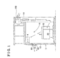
- Fig. 1 is a diagram schematically illustrating a configuration of an inside of a housing of an outdoor power generating apparatus according to a first embodiment
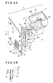
- Fig. 2A is an exploded perspective view illustrating a configuration of an exhaust passage of the outdoor power generating apparatus according to the first embodiment
- Fig. 2B is a partially enlarged cross-sectional diagram of a diversion passage of the outdoor power generating apparatus illustrated in Fig. 2A ;
- Fig. 3 is an exploded perspective view illustrating a configuration of a sound absorbing duct of the outdoor power generating apparatus according to the first embodiment
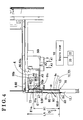
- Fig. 4 is a cross-sectional diagram illustrating the configuration of the exhaust passage of the outdoor power generating apparatus according to the first embodiment
- Fig. 5A is a cross-sectional diagram illustrating the configuration of the exhaust passage of the outdoor power generating apparatus according to the first embodiment
- Fig. 5B is an enlarged cross-sectional diagram of a shuttering portion according to a modified example of the power generating apparatus of the first embodiment.
- Fig. 6 is an enlarged perspective view illustrating an exhaust passage of an outdoor power generating apparatus according to another embodiment.
- a sound absorbing material which is used to configure a sound absorbing duct, has hydrophilicity or water repellency on a surface of the sound absorbing duct exposed to a curved passage.
- An area of an exhaust passage located relatively close to a generator chamber is formed to have the hydrophilicity.
- an area of the exhaust passage located relatively close to an exhaust port is formed to have hydrophobicity.
- the area of the exhaust passage located relatively close to the generator chamber is formed to have the hydrophobicity and the area of the exhaust passage located relatively close to the exhaust port is formed to have the hydrophilicity.
- the curved passage is formed so as to two-dimensionally or three-dimensionally curve. More specifically, the curved passage is curved so as to from an S-shape, an M-shape, a W-shape, an L-shape or the like. Furthermore, the sound absorbing material used for the sound absorbing duct does not necessarily have the hydrophilicity or the water repellency.
- a diversion passage is defined by an inner wall surface of a side wall of a housing so as to lead an exhaust gas to flow downwardly in a direction of gravity. More specifically, the diversion passage is formed so as to upwardly extend in a direction opposite to the direction of gravity along the inner wall surface of the side wall of the housing from the exhaust port of the housing. Furthermore, the diversion passage includes a sound absorbing body formed by a sound absorbing material. The sound absorbing body has the hydrophilicity or the water repellency on a surface thereof exposed to the diversion passage.
- the diversion passage is defined by the side wall of the housing and a diversion member facing the side wall of the housing.
- a value obtained by dividing LA by DA may be set in a range from five to one hundred (including five and one hundred). Accordingly, snow including powder snow and the like, rainwater and the like entering into the diversion passage from the exhaust port may not be allowed to pass through the diversion passage.
- the power generating apparatus is installed outdoor and is configured so that an engine 20 actuates a generator 22 (i.e. an engine-type generator). Furthermore, the power generating apparatus is adapted to a cogeneration system, which is configured so as to use exhausted heat of the engine 20. As illustrated in Fig. 1 , the power generating apparatus includes a housing 1, which is formed in a rectangular box shape and which includes a generator chamber 10 serving as an engine compartment (i.e. an engine room), a power generation source 2 provided at the generator chamber 10 of the housing 1, a ventilation fan 3 (see Fig.
- the housing 1 includes a first exterior panel 12 (a side wall portion) extending in a vertical direction of the housing 1 and a second exterior panel 14 (the side wall portion) extending in the vertical direction so as to be in parallel with the first exterior panel 12 while keeping a distance therefrom.
- An air intake port 120 is formed at an upper portion of the second exterior panel 14.
- the power generation source 2 is provided within the generator chamber 10 of the housing 1. Furthermore, the power generation source 2 includes the engine 20 and the generator 22.
- the engine 20 is configured so as to be driven in a manner where a gas fuel or a liquid fuel is combusted together with air.
- the generator 22 is provided within the generator chamber 10 of the housing 1 and is rotatably actuated by a driving shaft of the engine 20. Accordingly, in a case where the engine 20 is actuated and the generator 22 is driven in response to an actuation of the engine 20, an electric energy is generated.
- Illustrated in Fig. 2 is an exploded perspective view of the exhaust passage 4 through which the exhaust gas of the engine 20 is discharged into ambient air (i.e. outside air).
- the exhaust passage 4 includes a sound absorbing duct 5, a weir member 6, a weir passage 62, a diversion passage 7, and an exhaust port 8.
- the sound absorbing duct 5 is formed by a porous sound absorbing material (e.g. porous medium such as urethane form), which is used to form a curved passage 50.
- the curved passage 50 is formed to be in communication with the generator chamber 10 and so as to extend in a curved shape.
- the weir member 6 includes a shuttering portion 61, which is provided at a downstream side of the sound absorbing duct 5 and which is made of a sound absorbing material.
- the weir passage 62 is defined by the weir member 6 and the shuttering portion 61.
- the diversion passage 7 is provided at a downstream side of the shuttering portion 61. Furthermore, the diversion passage 7 is formed so as to change a direction of a flow of the exhaust gas (i.e. a direction indicated by arrows A5 and A6) from an outlet opening 50p of the curved passage 50 towards the weir passage 62 to a direction orthogonal to the direction of the flow of the exhaust gas (i.e. a direction indicated by an arrow A7, a downward direction of direction of gravity).
- the exhaust port 8 is provided at an end portion (e.g. a lower end portion) of the diversion passage 7 and opens at the first exterior panel 12 (the side wall) of the housing 1 so as to be exposed to the outside of the housing 1 (i.e. so as to be exposed to the ambient air). Furthermore, the exhaust port 8 is formed to open at a lower end portion 12d of the first exterior panel 12.
- the exhaust port 8 includes plural laterally-elongated holes 80, which are formed so as to extend in a lateral direction (i.e. a horizontal direction) while being in parallel with each other.
- the exhaust port 8 further includes plural cover portions 81 for covering an upper portion of respective laterally-elongated holes 80.
- each of the cover portions 81 is formed so as to downwardly incline in an outward direction in order to prevent the snow, the rainwater and the like from entering into the housing 1 from each of the laterally-elongated holes 80.
- a configuration of the exhaust port 8 is not limited to the above-described configuration example.
- the laterally-elongated holes 80 may be modified as vertical-elongated holes or round-shaped holes.
- the sound absorbing duct 5 includes a duct cover 51, a duct side wall portion 52 and a duct ceiling portion 54.
- the duct cover 51 which serves as a case, is made of metal or resin.
- the duct side wall portion 52 is lined at an inner wall surface of the duct cover 51 and is made of a porous and sound absorbing material (e.g. foamed urethane resin).
- the duct ceiling portion 54 includes an air regulation guide 53 having an inclined surface and made of a porous and sound absorbing material (e.g. foamed urethane resin).
- the duct ceiling portion 54 is fitted to an upper opening 52u of the duct side wall portion 52 while allowing the duct ceiling portion 54 to be attached to and detached from the upper opening 52u. In a case where the duct ceiling portion 54 is removed, the upper opening 52u of the duct side wall portion 52 is exposed, which may facilitate cleaning, maintenance and the like of the duct side wall portion 52.
- the air regulation guide 53 includes the inclined surface, which inclines upwardly relative to the horizontal direction indicated by an arrow A3 in order to smoothly guide the fuel gas to flow.
- the duct cover 51 includes first, second, third and fourth cover wall portions 51a, 51b, 51c and 51d, and a bottom wall portion 51e.
- the duct cover 51 also includes a fan opening 51 i opening downwardly so as to face the ventilation fan 3 and an outlet opening 51p opening laterally.
- the duct side wall portion 52 is made of the porous sound absorbing material.
- the duct side wall portion 52 includes the curved passage 50 bending in multiple directions, a first protruding wall portion 55, a second protruding wall portion 56, and a protruding wall portion 57.
- the first protruding wall portion 55 protrudes towards the curved passage 50.
- the second protruding wall portion 56 protrudes towards the curved passage 50 while facing the first protruding wall portion 55.
- the third protruding wall portion 57 protrudes towards the curved passage 50 while facing the first and second protruding wall portions 55 and 56.
- the curved passage 50 includes an S-shape passage 50s, an inlet opening 50i, and the outlet opening 50p.
- the S-shape passage 50s is formed to be curved in an S-shape in a plan view.
- the inlet opening 50i opens downward to the ventilation fan 3 in the vicinity of an inlet of the S-shape passage 50s so as to face the fan opening 51 i (which also serves as an inlet opening of the duct cover 51) of the duct cover 51.
- the outlet opening 50p opens laterally in the vicinity of an outlet of the S-shape passage 50s while facing the outlet opening 51p of the duct cover 51.
- the gas in the generator chamber 10 having heat flows upwardly in the direction indicated by the arrows A1 and then in a direction indicated by an arrow A2 through the inlet openings 50i and 51 i. Then, the gas entered into the sound absorbing duct 5 is guided to flow in the direction indicated by the arrow A3, in a direction indicated by an arrow A4, then in the direction indicated by the arrow A5 through the S-shape passage 50s while flow loss is controlled to be a minimum level by means of the air regulation guide 53 having the inclined surface. The gas is finally discharged from the outlet opening 50p.
- the exhaust gas flows three-dimensionally by turning multiple times within the duct side wall portion 52, a sufficient flow distance of the gas in the duct side wall portion 52 is ensured while achieving a downsize of the duct side wall portion 52 and increasing a sound absorption performance including a sound reduction.
- the first, second, and third protruding wall portions 55, 56, and 57 are provided at different portions at the curved passage 50 so as to face one another while forming the curved passage 50.
- a flow direction of the exhaust gas flowing through the exhaust passage 4 is changed multiple times, so that the sufficient flow distance of the exhaust gas may be ensured while achieving a downsize of the sound absorbing duct 5.
- the sound absorption performance including the sound reduction may be obtained.
- each of the first, second, and third protruding wall portions 55, 56, and 57 is formed to have a sufficient thickness and so as to extend in a height direction (i.e., in the direction of gravity, a direction indicated by an arrow G).
- the first, second, and third protruding wall portions 55, 56, and 57 have functions to forcibly change the direction of the exhaust gas flowing through the curved passage 50 and to reinforce the porous duct side wall portion 52.
- the diversion passage 7 is defined by an inner wall surface 12i of the first exterior panel 12 constituting the side wall of the housing 1, and a diversion member 70 formed in a thin frame shape.
- the diversion member 70 includes a frame body 71, a vertically elongated wall portion 72 and an opening portion 73.
- the frame body 71 is formed in a vertically elongated rectangular shape.
- the frame body 71 includes a flange portion 71a that extends outwardly.
- the vertically elongated wall portion 72 extends in the vertical direction (i.e. in the direction of gravity, the direction indicated by the arrow G) so as to cover an opening formed by the frame body 71.
- the opening portion 73 is formed at an upper portion of the vertically elongated wall portion 72. Furthermore, the opening portion 73 faces the weir passage 62 so as to be in communication therewith.
- a length of the diversion member 70 in the vertical direction i.e. the direction of gravity
- a length of the diversion member 70 in the direction orthogonal to the height direction of the first exterior panel 12 (the side wall portion) i.e. a thickness of the diversion member 70
- the length LA is set to be sufficiently greater than the thickness DA.
- the length DA corresponds to a size of the diversion member 70 in the direction orthogonal to the direction of gravity.
- the diversion member 70 is formed so as to extend in the height direction (i.e. the vertical direction, the direction of gravity).
- a value obtained by dividing the length LA by the thickness DA i.e. LA/DA
- LA/DA may be set to fall within a range from 5 and 100, specifically, from 5 and 50, more specifically, from 6 and 20.
- the diversion passage 7 formed by the diversion member 70 may be formed as a vertically elongated thin passage. Accordingly, the snow such as the powder snow, the rainwater and the like entering into the diversion passage 7 from the exhaust port 8 is unlikely to flow upwardly through the diversion passage 7.
- the power generating apparatus is configured so that the snow including the powder snow, the rainwater, and the like entering into the diversion passage 7 from the exhaust port 8 is discharged to the outside of the housing 1 from the laterally elongated hole 80 arranged at the lowest position out of plural laterally elongated holes 80.
- the diversion member 70 is formed into the vertically elongated shape in order to ensure the flow distance of the diversion member 70.
- the snow, the rainwater, and the like entering into the exhaust port 8 may be prevented from reaching the opening portion 73, the weir passage 62, the curved passage 50 in the housing 1, and further, the engine 20 and the generator 22 accommodated in the generator chamber 10 serving as the engine compartment.
- H 1 when a length from a lower end portion 8d of the exhaust port 8 to a lower end portion of the weir passage 62 (i.e. a top portion 61 m of the weir portion 61) is defined as H 1, the length H1 is set to be greater than the thickness DA and smaller than the length LA (LA>H1>DA).
- a value obtained by dividing the length H1 by the thickness DA may be set so as to be substantially equal to the value obtained by dividing the length LA by the thickness DA (LA/DA).
- the weir member 6 is positioned at the downstream side of the sound absorbing duct 5 and at the upstream side of the diversion member 70 in the flow direction (i.e. the direction indicated by the arrow A5 and the direction indicated by the arrow A6) of the exhaust gas from the engine 20.
- the weir member 6 includes a weir frame 60 having a rectangular shape, the shuttering portion 61 upwardly projecting from a lower portion 60d of the weir frame 60 to the top portion 61 m, and the weir passage 62 positioned above the shuttering portion 61 and opening laterally.
- the shuttering portion 61 may be made of the porous and sound absorbing material (e.g.
- the weir member 6 is arranged in the vicinity of the outlet opening 50p of the sound absorbing duct 5 so as to face the outlet opening 50p.
- a sound absorbing body 9 made of a sound absorbing material (e.g. a porous foam material such as a foamed resin, a foam metal and the like) is formed at the diversion passage 7.
- a porous material having foam cells intercommunicating with each other or a porous material having independent foam cells may be used as the porous foam material used for the sound absorbing body 9.
- the sound absorbing body 9 includes a first sound absorbing member 9f, a second sound absorbing member 9s and a third sound absorbing member 9t.
- the first sound absorbing member 9f is attached on the inner surface 12i of the first exterior panel 12 at a portion facing opposite to the outside of the housing 1 so as to be exposed to the diversion passage 7.
- the second sound absorbing member 9s is attached on an inner wall surface 72i of the vertically elongated wall portion 72 of the diversion member 70.
- the third sound absorbing member 9t is formed between the first sound absorbing member 9f and the second sound absorbing member 9S. Accordingly, the inner wall surface 72i of the diversion member 70 is covered with the sound absorbing material except for the opening portion 73.
- the diversion passage 7 is formed to have an elongated shape so as to extend in a height direction (i.e.
- the diversion passage 7 connects the exhaust port 8 of the housing 1 and the weir passage 62 so as to establish a communication therebetween.
- the diversion passage 7 is formed to extend towards the weir passage 62 in a direction opposite to the direction of gravity indicated by the arrow G along the inner wall surface 12i of the first exterior panel 12 (i.e. the side wall portion) of the housing 1 and the vertically elongated wall portion 72 of the diversion member 70.
- the power generating apparatus performs a power generating operation
- the fuel and the air used for a combustion operation are supplied to a combustion chamber of the engine 20, thereby driving the engine 20.
- the generator 22 is actuated in response to the actuation of the engine 20, thereby generating an electric power.
- Air which has heat emitted from the engine 20 and which remains within the generator chamber 10, is used as the exhaust gas and flows through the exhaust passage 4 in response to an actuation of the ventilation fan.
- the exhaust gas flows from the inlet opening 50i, the curved passage 50, the outlet opening 50p, the weir passage 62, the opening portion 73 and then to through the diversion passage 7 downwardly in the direction of gravity indicated by the arrow G, thereby being emitted to the outside of the housing 1 (emitted into the outside air) through the exhaust port 8 of the first exterior panel 12 of the housing 1.
- the exhaust gas flows in the directions indicated by the arrows A1, A2, A3, A4, A5, A6, A7 and A8 in the above-mentioned order.
- An outlet cross-sectional dimension i.e.
- the across-sectional dimension of a minimal flow passage) of the weir passage 62 may be formed to have an approximately equal dimension as a cross-sectional dimension of a minimal flow passage of the curved passage 50.
- the weir passage 62 is connected to the outside of the housing 1 through the diversion passage 7. Therefore, the sound (the noise) and the like may be avoided from leaking to the outside of the power generating apparatus while lowering flow resistance.
- the power generating apparatus is not limited to the configuration disclosed in this embodiment.
- the cross-sectional dimension of the fluid passage may be changed to any desired size along the upstream side to the downstream side of the flow direction of the exhaust gas.
- the sound absorbing body 9 or the sound absorbing material is provided at the exhaust passage 4. Furthermore, the sound absorbing duct 5, which is made of the sound absorbing material, is provided at the power generating apparatus. Still further, the shuttering portion 61 is made of the sound absorbing member. Therefore, an operation noise generated from the engine 20, the generator 22, and the ventilation fan 3 may be reduced. Still further, because the curved passage 50 is formed to extend in the S-shape when being viewed from above, a propagation distance of sound is secured so as to reduce the operation sound, while achieving the downsize of the power generating apparatus.
- the diversion passage 7, which is provided at the downstream side of the shuttering portion 61, is formed to change the flow direction of the exhaust gas so that the exhaust gas flows downwardly in the direction of gravity indicated by the arrow G so as to be orthogonal to the flow direction (i.e. the direction indicated by the arrows A5 and A6) along which the exhaust gas flows from the outlet opening 50p of the curved passage 50 towards the weir passage 62.
- the exhaust port 8 is provided so as to be located at a lower end portion (i.e. an edge portion) of the diversion passage 7. Therefore, even if the power generating apparatus is used under the adverse weather condition (i.e.
- the exhaust gas from the engine 20 flows through the exhaust passage 4 and accordingly, is emitted from the exhaust port 8 of the housing 1 as long as the engine 20 is driven. Accordingly, in this case, the snow (e.g. the powder snow and the like), the rainwater and the like in the outside air may be avoided from entering into the exhaust passage 4 from the exhaust port 8.
- the snow e.g. the powder snow and the like
- the rainwater and the like in the outside air may be avoided from entering into the exhaust passage 4 from the exhaust port 8.
- the exhaust gas from the engine 20 is not emitted to the outside air from the exhaust port 8 of the housing 1. Accordingly, generally, in the case of the adverse weather condition such as a heavy snowstorm and a heavy rain, the snow such as the powder snow, the rain and the like may enter into the diversion passage 7 of the housing 1 from the exhaust port 8. Furthermore, generally, even in a case where the engine 20 is driven to idle, the snow such as the powder snow, the rainwater and the like may enter into the diversion passage 7 from the exhaust port 8 in the case of the advert weather condition such as the heavy snowstorm, the heavy rain and the like depending on circumstances.
- the adverse weather condition such as a heavy snowstorm and a heavy rain
- the snow such as the powder snow, the rain and the like may enter into the diversion passage 7 from the exhaust port 8 in the case of the advert weather condition such as the heavy snowstorm, the heavy rain and the like depending on circumstances.
- the snow such as the powder snow, the rainwater and the like entered into the diversion passage 7 from the exhaust port 8 is not likely to enter into the weir passage 62 unless the snow such as the powder snow, the rainwater and the like upwardly move so as to resist against a gravity (i.e. in a direction opposite to the direction indicated by the arrow A7). Accordingly, the snow such as the powder snow, the rainwater and the like are prevented from entering into the curved passage 50 and further, into the engine 20 provided within the generator chamber 10.
- the diversion passage 7 is formed to have a narrow passage (a thin passage), the snow such as the powder snow, the rainwater and the like is not likely to move upwardly within the diversion passage 7 so as to resist against the gravity, even if the snow such as the powder snow, the rainwater and the like enters into the diversion passage 7 from the exhaust port 8.
- the shuttering portion 61 includes an upwardly extending wall surface 61a and an inclined wall surface 61c (i.e. an inclined portion).
- the upwardly extending wall surface 61 a is formed at the shuttering portion 61 so as to be located closer to the diversion passage 7.
- the inclined wall surface 61c is formed at the shuttering portion 61 so as to be located closer to the curved passage 50. More specifically, the upwardly extending wall surface 61 a is formed at the shuttering portion 61 so as to upwardly extend from the lower portion 60d of the weir frame 60 along the direction of gravity indicated by the arrow G.
- the upwardly extending wall surface 61 a upwardly protrudes in the vertical direction up to the top portion 61m.
- the inclined wall surface 61 c is formed to upwardly incline towards the top portion 61 m along the flow direction (i.e. the direction indicated by the arrows A5 and A6) of the exhaust gas. Accordingly, emission of the exhaust gas, which flows from the curved passage 50 towards the exhaust port 8, is ensured. As a result, ventilation of the exhaust gas, which is emitted from the engine 20, may be ensured.
- the upwardly extending wall surface 61a of the shuttering portion 61 is formed to as to upwardly protrude in the vertical direction from the lower portion 60d of the weir frame 60 so as to resist against the gravity as illustrated in Fig. 5A , the upwardly extending wall surface 61a ensures a blocking performance against the snow such as the powder snow, the rainwater and the like entered into the exhaust passage 4 from the exhaust port 8, and further, against a fine object such as grit, dust and the like. Accordingly, the snow such as the powder snow, the rainwater, the grit, the dust and the like may be appropriately and properly prevented from flowing towards the curved passage 50 from the exhaust port 8.
- the upwardly extending wall surface 61a is not limited to the above-explained example where the upwardly extending wall surface 61 a extends in the vertical direction.
- the upwardly extending wall surface 61a may be formed to incline in the same direction as the inclined wall surface 61 c inclines.
- a second embodiment of a power generating apparatus will be described below.
- the power generating apparatus according to the second embodiment has a similar configuration as the power generating apparatus according to the first embodiment, therefore, the power generating apparatus according to the second embodiment achieves advantages and merits similar to the power generating apparatus according to the first embodiment. Therefore, in the second embodiment, only the differences between the power generating apparatus according to the first embodiment and the power generating apparatus according to the first embodiment will be described below with reference to Figs. 1 to 5A .
- the sound absorbing material which is used for the duct side wall portion 52 of the exhaust passage 4, the sound absorbing body 9 and the shuttering member 61, may be formed to have a water repellent configuration having water repellency against moisture.
- the sound absorbing member itself which configures the duct side wall portion 52, the sound absorbing body 9 and the shuttering portion 61
- a water repellent film may be laminated (layered) on a surface of the sound absorbing material, which is used for each of the duct side wall portion 52, the sound absorbing body 9 and the shuttering portion 61.
- a water repellent film, onto which a fluorine-based material is coated may be formed on a surface of each of the duct side wall portion 52, the sound absorbing body 9 and the shuttering portion 61.
- the sound absorbing material which configures each of the duct side wall portion 52, the sound absorbing body 9 and the shuttering portion 61, may include the water repellency against water.
- the water repellency indicates a property of repelling the water. More specifically, the water repellency refers to a property in which a contact angle between an object and a water drop is great.
- a contact angle ⁇ of the water drop on a solid surface is used as a reference (an index).
- the solid surface is referred to have the water repellency (i.e. the hydrophobicity).
- the solid surface in a case where the contact angle ⁇ falls within a range between 110 degrees and 150 degrees, the solid surface is referred to have high water repellency. Still further, in a case where the contact angle ⁇ is equal to or greater than 150 degrees, the solid surface is referred to have super water repellency.
- the water repellency includes the high water repellency and the super water repellency.
- the snow such as the powder snow, the rainwater and the like enteres into the exhaust passage 4 from the exhaust port 8 of the first exterior panel 12 facing outdoor because of the adverse weather condition the snow such as the powder snow, the rainwater and the like entered into the exhaust passage 4 may remain within the exhaust passage 4 as water drops without being absorbed into the sound absorbing material, which configures each of the duct side wall portion 52, the sound absorbing body 9 and the shuttering portion 61.
- the water repellent material is used, the water drops on a water repelling surface of the exhaust passage 4 are easily repelled and moved.
- the moisture (i.e. the water drops and the like) remaining on the exhaust passage 4 may be forcibly and easily emitted into the outside air from the exhaust port 8 of the first exterior panel 12 via the exhaust passage 4 in response to the emission of the exhaust gas having the heat from the generator chamber 10 of the housing 1 towards the exhaust port 8 via the exhaust passage 4.
- the exhaust passage 4 is formed to have the water repellency, the water drops may be easily displaced along the exhaust passage 2 in response to the flow of the exhaust gas so as to be emitted into the outside air from the exhaust port 8. Therefore, a damage of a component, an equipment and the like provided within the housing 1 by corrosion caused by the moisture may be reduced.
- a third embodiment of a power generating apparatus will be described below.
- the power generating apparatus according to the third embodiment has a similar configuration as the power generating apparatus according to the first embodiment, therefore, the power generating apparatus according to the third embodiment achieves advantages and merits similar to the power generating apparatus according to the first embodiment. Accordingly, only the differences between the power generating apparatus according to the first embodiment and the power generating apparatus according to the second embodiment will be described below with reference to Figs. 1 to 5A .
- At least a surface of the sound absorbing material, which is used for the duct side wall portion 52 of the sound absorbing duct 5 is formed to have a hydrophilic configuration, so that the surface of the duct side wall portion 52 exposed to the curved passage 50 has the hydrophilicity.
- the hydrophilicity refers to property where the contact angle ⁇ of the water drop on the surface of the solid object is small and where the surface is hydrophilic. Generally, the contact angle ⁇ being less than 90 degrees is defined as the hydrophilicity.
- each of the duct side wall portion 52, the sound absorbing body 9 and the shuttering portion 61, which are provided at the exhaust passage 4 is formed to have the hydrophilicity, so that the water drops are less likely to be generated on the surface of each of the duct side wall portion 52, the sound absorbing body 9 and the shuttering portion 61 of the exhaust passage 4.
- the sound absorbing material which is used for each of the duct side wall portion 52, the sound absorbing body 9 and the shuttering portion 61 provided at the exhaust passage 4, is formed with a porous hydrophilic material.
- the porous hydrophilic material may be formed to have a water absorbable sponge-like property. More specifically, the porous hydrophilic material may be formed so that a ratio of foam cells that interconnect with neighboring foam cells is high. Furthermore, at least the surface of the sound absorbing material may be formed to be porous.
- the snow such as the powder snow, the rainwater and the like may be absorbed into the sound absorbing material, which is formed as the water absorbable porous material used for each of the duct side wall portion 52, the sound absorbing body 9 and the shuttering portion 61 of the exhaust passage 4, as the moisture.
- the sound absorbing material which is formed as the water absorbable porous material used for each of the duct side wall portion 52, the sound absorbing body 9 and the shuttering portion 61 of the exhaust passage 4, as the moisture.
- the exhaust gas which is exhausted from the generator chamber 10 of the housing 1 and which has the heat, passes through the exhaust passage 4 and then, the exhaust gas is emitted to the outside air from the exhaust port 8 of the first exterior panel 12 while the snow such as the powder snow, the rainwater and the like are absorbed into the sound absorbing material, which is used for the duct side wall portion 52, the sound absorbing body 9 and the shuttering portion 61 of the exhaust passage 4, as the moisture.
- the moisture absorbed into the sound absorbing material, which is used for the duct side wall portion 52, the sound absorbing body 9 and the shuttering portion 61 of the exhaust passage 4 may be appropriately and properly dried by the heat of the exhaust gas flowing through the exhaust passage 4.
- the moisture dried by the exhaust gas may be emitted into the ambient air together with the exhaust gas from the exhaust port 8. Therefore, the excessive amount of the water is prevented from entering into the engine 20, which is provided within the generator chamber 10. Still further, the damage of the component, the equipment and the like mounted within the housing 1 caused by the corrosion thereof may be avoided. Additionally, because drying the absorbed moisture accompanies latent heat of vaporization (i.e. absorption of heat), cooling performance of the power generating apparatus in the vicinity of the exhaust passage 4, the generator chamber 10 and the like may be increased. As a result, excessive heating of the exhaust passage 4, the generator chamber 10 and the like may be avoided.
- a fourth embodiment of a power generating apparatus will be described below.
- the power generating apparatus according to the fourth embodiment has a similar configuration as the power generating apparatus according to the first embodiment, therefore, the power generating apparatus according to the fourth embodiment achieves advantages and merits similar to the power generating apparatus according to the first embodiment. Therefore, only the differences between the power generating apparatus according to the first embodiment and the power generating apparatus according to the fourth embodiment will be described below with reference to Figs. 1 to 5A .
- an area of the exhaust passage 4 located relatively closer to the generator chamber 10 i.e. a downstream area of the exhaust passage 4
- an area of the exhaust passage 4 located relatively closer to the exhaust port 8 i.e.
- an upstream area of the exhaust passage 4 is formed to have the hydrophobicity.
- a length of the exhaust passage 4 corresponding to an entire flow passage of the exhaust passage 4 is relatively indicated as 100
- the area of the exhaust passage 4 located relatively closer to the generator chamber 10 corresponds to an area (a length) of zero (0) to fifty (50) from the generator chamber 10, or an area (a length) of zero (0) to forty (40).
- the area (the length) of the portion of the exhaust passage 4 located closer to the generator chamber 10 is not limited to the above-mentioned range.
- the power generating apparatus may be modified so that the sound absorbing material itself, which is used for the sound absorbing body 9 and the shuttering portion 61 (i.e. the area of the exhaust passage 4 located relatively closer to the exhaust port 8), may be formed to have the water repellency.
- the water repellent film may be laminated on the surface of the sound absorbing material, which is used to configure each of the sound absorbing body 9 and the shuttering portion 61.
- the sound absorbing material used for the duct side wall portion 52 i.e. the area of the exhaust passage 4 located relatively closer to the generator chamber 10) may be formed by the porous material so as to have the water absorbability, in other words, so as to have the hydrophilicity.
- the duct side wall portion 52 is located at a position closer to the generator chamber 10 relative to the diversion passage 7 and the weir passage 62. Therefore, in this case, the moisture flowing into the generator chamber 10 may be absorbed by the duct side wall portion 52 in order to avoid the moisture such as the water drops and the like from dropping into the generator chamber 10. Still further, a temperature of the exhaust gas flowing towards the exhaust port 8 from the generator chamber 10 is generally and relatively higher at an area of the duct side wall portion 52 located closer to the generator chamber 10. Therefore, the area of the duct side wall portion 52 located closer to the generator chamber 10 has a high drying performance. Moreover, drying the moisture accompanies the latent heat of vaporization (i.e. the absorption of heat), the cooling performance of the power generating apparatus in the vicinity of the generator chamber 10 and the like may be increased. As a result, the excessive heating of the generator chamber 10 and the like may be avoided.
- a fifth embodiment of a power generating apparatus will be described below with reference to Fig. 6 .
- the power generating apparatus according to the fifth embodiment has a similar configuration to the power generating apparatus according to the first embodiment, therefore, the power generating apparatus according to the fifth embodiment achieves advantages and merits similar to the power generating apparatus according to the first embodiment. Therefore, only the differences between the power generating apparatus according to the first embodiment and the power generating apparatus according to the fifth embodiment will be described below.
- a fuel cell 28 is provided within the generator chamber 10 of the housing 1 as a power generation source.
- the fuel cell 28 may be configured as a polymer electrolyte fuel cell (PEFC), a solid oxide fuel cell (SOFC) or a phosphoric acid fuel cell (PAFC).
- PEFC polymer electrolyte fuel cell
- SOFC solid oxide fuel cell
- PAFC phosphoric acid fuel cell
- the fuel cell may be configured as a low temperature-type fuel cell, a middle temperature-type fuel cell, or a high temperature-type fuel cell.
- an anode fluid e.g. a hydrogen gas, a hydrogen bearing gas and the like
- a cathode fluid e.g. an oxygen gas, an oxygen bearing gas and the like
- the ventilation fan 3 is actuated in response to an electric power generating performance of the fuel cell 28.
- the heat and the air within the generator chamber 10 of the housing 1 is emitted from the generator chamber 10 to the curved passage 50 of the sound absorbing duct 5 as the exhaust gas. Furthermore, the exhaust gas flows though the weir passage 62 and the diversion passage 7 so that the exhaust gas is emitted to the outside air from the exhaust port 8.
- the sound absorbing material which is used to form each of the duct side wall portion 52, the sound absorbing body 9 and the shuttering portion 61 of the exhaust passage 4, may be formed to have the hydrophilicity, the water absorbability, or the water repellency.
- the sound absorbing material which is used to configure the sound absorbing body 9 and the shuttering portion 61, may be formed so that at least the surface thereof has the water repellency.
- the water repellent film may be laminated on the surface of the sound absorbing material, which is used to form each of the sound absorbing body 9 and the shuttering portion 61.
- at least the surface of the sound absorbing material of the duct side wall portion 52 at the portion thereof located closer to the generator chamber 10 may be formed to have the water absorbing porous property, in other words, so as to have the hydrophilicity.
- the power generating apparatus is not limited to the above-described embodiments and examples.
- the power generating apparatus may be modified and changed without departing from the scope of the disclosure.
- the shuttering portion 61 is made of the porous sound absorbing material.
- a non-porous metal, a ceramic, a rigid resin or the like may be adapted as a material used for the shuttering portion 61.
- the shuttering portion 61 may be formed to extend vertically.
- the diversion passage 7 is provided with the first, second and third sound absorbing members 9f, 9s and 9t.
- the curved passage 50 is formed to three-dimensionally extend in the S-shape.
- the curved passage 50 may be extended to form an M-shape, an N-shape, a W-shape, a V-shape, an L-shape, a Z-shape or the like.
- a porous material having the sound absorbability but not having the water absorbability may be adapted.
Landscapes
- Engineering & Computer Science (AREA)
- Chemical & Material Sciences (AREA)
- Combustion & Propulsion (AREA)
- Mechanical Engineering (AREA)
- General Engineering & Computer Science (AREA)
- Physics & Mathematics (AREA)
- Acoustics & Sound (AREA)
- Exhaust Silencers (AREA)
- Fuel Cell (AREA)
Applications Claiming Priority (1)
| Application Number | Priority Date | Filing Date | Title |
|---|---|---|---|
| JP2010136092A JP5637360B2 (ja) | 2010-06-15 | 2010-06-15 | 屋外設置型発電装置 |
Publications (2)
| Publication Number | Publication Date |
|---|---|
| EP2397667A2 true EP2397667A2 (de) | 2011-12-21 |
| EP2397667A3 EP2397667A3 (de) | 2012-08-22 |
Family
ID=44582100
Family Applications (1)
| Application Number | Title | Priority Date | Filing Date |
|---|---|---|---|
| EP11169575A Withdrawn EP2397667A3 (de) | 2010-06-15 | 2011-06-10 | Außenstromerzeugungsvorrichtung |
Country Status (4)
| Country | Link |
|---|---|
| US (1) | US20110303482A1 (de) |
| EP (1) | EP2397667A3 (de) |
| JP (1) | JP5637360B2 (de) |
| CA (1) | CA2743130A1 (de) |
Cited By (2)
| Publication number | Priority date | Publication date | Assignee | Title |
|---|---|---|---|---|
| US9243586B2 (en) | 2010-10-20 | 2016-01-26 | Honda Motor Co., Ltd. | Ventilation outlet structure of cogeneration system |
| CN106996204A (zh) * | 2017-05-04 | 2017-08-01 | 中国航发沈阳发动机研究所 | 一种用于风扇/增压级气动噪声试验的消声室 |
Families Citing this family (11)
| Publication number | Priority date | Publication date | Assignee | Title |
|---|---|---|---|---|
| JP5637361B2 (ja) * | 2010-06-16 | 2014-12-10 | アイシン精機株式会社 | 屋外設置型発電装置 |
| JP2013170467A (ja) * | 2012-02-17 | 2013-09-02 | Honda Motor Co Ltd | エンジン駆動発電機 |
| JP2013256904A (ja) * | 2012-06-13 | 2013-12-26 | Nippon Sharyo Seizo Kaisha Ltd | エンジン作業機 |
| JP6040654B2 (ja) * | 2012-09-13 | 2016-12-07 | アイシン精機株式会社 | 屋外設置型発電装置 |
| CN105674460B (zh) * | 2016-04-12 | 2020-08-11 | 瑞安市源霸机械制造有限公司 | 排风机 |
| JP6770354B2 (ja) * | 2016-07-06 | 2020-10-14 | 日本車輌製造株式会社 | 吸気ダクト及びエンジン作業機 |
| US10962310B2 (en) | 2017-01-12 | 2021-03-30 | Kohler Co. | Remote radiator for a generator system |
| JP7484359B2 (ja) * | 2020-04-09 | 2024-05-16 | 株式会社アイシン | 筐体の換気構造 |
| JP7041908B1 (ja) | 2021-09-30 | 2022-03-25 | 一般社団法人発電機協会 | 発電装置 |
| WO2025170569A1 (en) * | 2024-02-05 | 2025-08-14 | Generac Power Systems, Inc. | Sound reduction system for a generator |
| JP2025181250A (ja) * | 2024-05-31 | 2025-12-11 | 三菱重工エンジン&ターボチャージャ株式会社 | エンジン、および発電セット |
Citations (3)
| Publication number | Priority date | Publication date | Assignee | Title |
|---|---|---|---|---|
| JPH11200951A (ja) | 1998-01-13 | 1999-07-27 | Kubota Corp | コージェネレーション装置 |
| JP2006009678A (ja) | 2004-06-25 | 2006-01-12 | Aisin Seiki Co Ltd | コージェネレーション装置 |
| JP2007172946A (ja) | 2005-12-20 | 2007-07-05 | Toshiba Fuel Cell Power Systems Corp | 燃料電池エンクロージャ及び防音パネル |
Family Cites Families (18)
| Publication number | Priority date | Publication date | Assignee | Title |
|---|---|---|---|---|
| US4951871A (en) * | 1988-10-04 | 1990-08-28 | Kubota Ltd. | Sound-proof type engine working machine with waste heat recovery apparatus |
| JPH04116221A (ja) * | 1990-09-04 | 1992-04-16 | Kubota Corp | エンジン収容ケースの冷却排風排出装置 |
| JPH08232677A (ja) * | 1994-12-27 | 1996-09-10 | Kubota Corp | 包囲型エンジンの騒音低減装置 |
| JPH08261009A (ja) * | 1995-03-27 | 1996-10-08 | Kubota Corp | 防音型エンジン |
| DE19821532A1 (de) * | 1998-05-14 | 1999-11-25 | Hp Chemie Pelzer Res & Dev | Wärme- und schalldämmende Verkleidung für den Motorraum von Kraftfahrzeugen sowie ein Verfahren zu dessen Herstellung |
| JP3984732B2 (ja) * | 1998-10-06 | 2007-10-03 | ヤンマー株式会社 | エンジン作業機のパッケージにおける駆動音低減装置 |
| US6463905B1 (en) * | 1998-10-06 | 2002-10-15 | Yanmar Diesel Engine Co., Ltd. | Low noise package storing type engine working machine |
| JP3375563B2 (ja) * | 1999-03-30 | 2003-02-10 | 株式会社クボタ | 防音型エンジン発電機 |
| JP2002070571A (ja) * | 2000-08-28 | 2002-03-08 | Mitsui Zosen Machinery & Service Inc | 自家発電装置 |
| JP2002129976A (ja) * | 2000-10-24 | 2002-05-09 | Nippon Sharyo Seizo Kaisha Ltd | 防音構造ケーシングの吸気ダクト構造 |
| JP3712664B2 (ja) * | 2001-07-10 | 2005-11-02 | ヤンマー株式会社 | 防音型発電装置 |
| DE10143167A1 (de) * | 2001-09-04 | 2003-03-27 | Hp Chem Pelzer Res & Dev Ltd | Wärme- und schalldämmende Verkleidung für den Motorraum von Kraftfahrzeugen |
| EP1536674B1 (de) * | 2002-06-24 | 2017-01-11 | Tabuchi Electric Co., Ltd. | Ausseninstallierte stromversorgungsaufbereitungseinrichtung |
| ITRE20040079A1 (it) * | 2004-07-06 | 2004-10-06 | Eurosystems Spa | Gruppo elettrogeno perfezionato |
| JP4950497B2 (ja) * | 2006-01-25 | 2012-06-13 | 東芝燃料電池システム株式会社 | 燃料電池発電装置およびその換気方法 |
| JP5162118B2 (ja) * | 2006-10-20 | 2013-03-13 | アイシン精機株式会社 | 燃料電池システム |
| JP2008192528A (ja) * | 2007-02-07 | 2008-08-21 | Toshiba Corp | 燃料電池発電装置およびその換気装置 |
| JP5637361B2 (ja) * | 2010-06-16 | 2014-12-10 | アイシン精機株式会社 | 屋外設置型発電装置 |
-
2010
- 2010-06-15 JP JP2010136092A patent/JP5637360B2/ja not_active Expired - Fee Related
-
2011
- 2011-06-10 EP EP11169575A patent/EP2397667A3/de not_active Withdrawn
- 2011-06-13 CA CA2743130A patent/CA2743130A1/en not_active Abandoned
- 2011-06-14 US US13/159,715 patent/US20110303482A1/en not_active Abandoned
Patent Citations (3)
| Publication number | Priority date | Publication date | Assignee | Title |
|---|---|---|---|---|
| JPH11200951A (ja) | 1998-01-13 | 1999-07-27 | Kubota Corp | コージェネレーション装置 |
| JP2006009678A (ja) | 2004-06-25 | 2006-01-12 | Aisin Seiki Co Ltd | コージェネレーション装置 |
| JP2007172946A (ja) | 2005-12-20 | 2007-07-05 | Toshiba Fuel Cell Power Systems Corp | 燃料電池エンクロージャ及び防音パネル |
Cited By (3)
| Publication number | Priority date | Publication date | Assignee | Title |
|---|---|---|---|---|
| US9243586B2 (en) | 2010-10-20 | 2016-01-26 | Honda Motor Co., Ltd. | Ventilation outlet structure of cogeneration system |
| CN106996204A (zh) * | 2017-05-04 | 2017-08-01 | 中国航发沈阳发动机研究所 | 一种用于风扇/增压级气动噪声试验的消声室 |
| CN106996204B (zh) * | 2017-05-04 | 2019-09-06 | 中国航发沈阳发动机研究所 | 一种用于风扇增压级气动噪声试验的消声室 |
Also Published As
| Publication number | Publication date |
|---|---|
| US20110303482A1 (en) | 2011-12-15 |
| JP5637360B2 (ja) | 2014-12-10 |
| EP2397667A3 (de) | 2012-08-22 |
| CA2743130A1 (en) | 2011-12-15 |
| JP2012002097A (ja) | 2012-01-05 |
Similar Documents
| Publication | Publication Date | Title |
|---|---|---|
| EP2397667A2 (de) | Außenstromerzeugungsvorrichtung | |
| EP2397666B1 (de) | Außenstromerzeugungsvorrichtung | |
| CN101981314B (zh) | 风力发电装置 | |
| CN115164281A (zh) | 一种空调室内机 | |
| CN111380106A (zh) | 柜式空调内机及具有其的空调器 | |
| KR20110095560A (ko) | 공냉식 연료 전지 | |
| CN215860456U (zh) | 一种利于机舱降温的散热器导风板组件 | |
| CN211476099U (zh) | 空调器 | |
| CN212585163U (zh) | 一种风道式恒温机房 | |
| CN219415150U (zh) | 风道组件、新风装置及新风空调 | |
| CN222663587U (zh) | 散热结构及车辆 | |
| CN223691204U (zh) | 加湿模块、空气处理部件和空调器 | |
| CN121047752B (zh) | 一种风电机舱排气消声器 | |
| CN116231487B (zh) | 预装式变电站 | |
| CN215921825U (zh) | 一种导风组件及驻车空调 | |
| CN214065251U (zh) | 一种低噪音商用空调用出风口机构 | |
| CN222813676U (zh) | 液冷装置、储能集装箱及机车 | |
| CN220229377U (zh) | 一种空调器 | |
| CN224151149U (zh) | 壳体组件和空调器 | |
| CN219339231U (zh) | 一种充电桩 | |
| CN111594971A (zh) | 一种排风装置及空调器 | |
| CN222597871U (zh) | 一种风管机及空调器 | |
| CN211575264U (zh) | 空调器 | |
| CN114523841B (zh) | 动力舱及具有其的工程机械 | |
| CN222911778U (zh) | 空调室内机 |
Legal Events
| Date | Code | Title | Description |
|---|---|---|---|
| AK | Designated contracting states |
Kind code of ref document: A2 Designated state(s): AL AT BE BG CH CY CZ DE DK EE ES FI FR GB GR HR HU IE IS IT LI LT LU LV MC MK MT NL NO PL PT RO RS SE SI SK SM TR |
|
| AX | Request for extension of the european patent |
Extension state: BA ME |
|
| PUAI | Public reference made under article 153(3) epc to a published international application that has entered the european phase |
Free format text: ORIGINAL CODE: 0009012 |
|
| PUAL | Search report despatched |
Free format text: ORIGINAL CODE: 0009013 |
|
| AK | Designated contracting states |
Kind code of ref document: A3 Designated state(s): AL AT BE BG CH CY CZ DE DK EE ES FI FR GB GR HR HU IE IS IT LI LT LU LV MC MK MT NL NO PL PT RO RS SE SI SK SM TR |
|
| AX | Request for extension of the european patent |
Extension state: BA ME |
|
| RIC1 | Information provided on ipc code assigned before grant |
Ipc: F02B 77/11 20060101ALI20120713BHEP Ipc: F02B 63/04 20060101AFI20120713BHEP |
|
| STAA | Information on the status of an ep patent application or granted ep patent |
Free format text: STATUS: THE APPLICATION IS DEEMED TO BE WITHDRAWN |
|
| 18D | Application deemed to be withdrawn |
Effective date: 20130223 |