EP2397631A2 - Installation de porte coulissante et procédé de montage d'une installation de porte coulissante - Google Patents
Installation de porte coulissante et procédé de montage d'une installation de porte coulissante Download PDFInfo
- Publication number
- EP2397631A2 EP2397631A2 EP11169213A EP11169213A EP2397631A2 EP 2397631 A2 EP2397631 A2 EP 2397631A2 EP 11169213 A EP11169213 A EP 11169213A EP 11169213 A EP11169213 A EP 11169213A EP 2397631 A2 EP2397631 A2 EP 2397631A2
- Authority
- EP
- European Patent Office
- Prior art keywords
- roller carriage
- sliding
- guide rail
- sliding door
- door system
- Prior art date
- Legal status (The legal status is an assumption and is not a legal conclusion. Google has not performed a legal analysis and makes no representation as to the accuracy of the status listed.)
- Ceased
Links
Images


Classifications
-
- E—FIXED CONSTRUCTIONS
- E05—LOCKS; KEYS; WINDOW OR DOOR FITTINGS; SAFES
- E05D—HINGES OR SUSPENSION DEVICES FOR DOORS, WINDOWS OR WINGS
- E05D15/00—Suspension arrangements for wings
- E05D15/06—Suspension arrangements for wings for wings sliding horizontally more or less in their own plane
- E05D15/0621—Details, e.g. suspension or supporting guides
- E05D15/0626—Details, e.g. suspension or supporting guides for wings suspended at the top
- E05D15/0652—Tracks
-
- E—FIXED CONSTRUCTIONS
- E05—LOCKS; KEYS; WINDOW OR DOOR FITTINGS; SAFES
- E05Y—INDEXING SCHEME ASSOCIATED WITH SUBCLASSES E05D AND E05F, RELATING TO CONSTRUCTION ELEMENTS, ELECTRIC CONTROL, POWER SUPPLY, POWER SIGNAL OR TRANSMISSION, USER INTERFACES, MOUNTING OR COUPLING, DETAILS, ACCESSORIES, AUXILIARY OPERATIONS NOT OTHERWISE PROVIDED FOR, APPLICATION THEREOF
- E05Y2600/00—Mounting or coupling arrangements for elements provided for in this subclass
-
- E—FIXED CONSTRUCTIONS
- E05—LOCKS; KEYS; WINDOW OR DOOR FITTINGS; SAFES
- E05Y—INDEXING SCHEME ASSOCIATED WITH SUBCLASSES E05D AND E05F, RELATING TO CONSTRUCTION ELEMENTS, ELECTRIC CONTROL, POWER SUPPLY, POWER SIGNAL OR TRANSMISSION, USER INTERFACES, MOUNTING OR COUPLING, DETAILS, ACCESSORIES, AUXILIARY OPERATIONS NOT OTHERWISE PROVIDED FOR, APPLICATION THEREOF
- E05Y2800/00—Details, accessories and auxiliary operations not otherwise provided for
- E05Y2800/69—Permanence of use
- E05Y2800/692—Temporary use, e.g. removable tools
-
- E—FIXED CONSTRUCTIONS
- E05—LOCKS; KEYS; WINDOW OR DOOR FITTINGS; SAFES
- E05Y—INDEXING SCHEME ASSOCIATED WITH SUBCLASSES E05D AND E05F, RELATING TO CONSTRUCTION ELEMENTS, ELECTRIC CONTROL, POWER SUPPLY, POWER SIGNAL OR TRANSMISSION, USER INTERFACES, MOUNTING OR COUPLING, DETAILS, ACCESSORIES, AUXILIARY OPERATIONS NOT OTHERWISE PROVIDED FOR, APPLICATION THEREOF
- E05Y2900/00—Application of doors, windows, wings or fittings thereof
Definitions
- the invention relates to a sliding door system according to the preamble of patent claim 1 and a method for assembling a sliding door system according to claim 9.
- roller carriage In practice, during installation of the sliding door system, situations occur in which the roller carriage is to be placed in the guide rail before the sliding leaf is mounted, or can only be removed from the guide rail after the sliding leaf has been removed. Then the roller carriage must be moved by a first person in his intended, i. the coupling of the sliding wing permitting position are held until a second person has introduced the sliding sash and made the connection between the roller carriage and the sliding sash. When using two roller carriages, even a third person may be required if the roller carriages have a relatively large distance from each other.
- the invention has for its object to provide a sliding door system which is easy to install, in particular with regard to the connection between the sliding leaf and the roller carriage.
- an auxiliary assembly device which can be arranged between the roller carriage and the guide rail, wherein the auxiliary assembly device with disassembled sliding wing fixed the roller carriage in its intended position, and wherein the auxiliary assembly device after the connection between the sliding leaf and the roller carriage can be disassembled.
- the assembly aid device can be connected without tools to the guide rail or the roller carriage, whereby the assembly of the sliding door system can be further simplified.
- the mounting aid comprises at least one handle portion, at least one cooperating with the roller carriage mounting area and at least one cooperating with the guide rail mounting area, a simple, well-defined handling of the mounting aid is guaranteed.
- the mounting areas of the auxiliary assembly device can cooperate with associated receiving areas of the guide rail and the roller carriage, resulting in a secure fit of the assembly aid.
- At least one of the mounting areas of the mounting auxiliary device may comprise at least one molding adapted to the receiving areas of the guide rail, e.g. have a rounding and / or edge, whereby a simple attachment or detachment of the mounting aid can be achieved, e.g. by a rotating movement of the grip area.
- At least two roller carriages which can be connected to one another by means of a coupling element, can be provided per sliding leaf.
- the assigned to the roller carriage receiving area for the auxiliary assembly device may be arranged on the coupling element, whereby the entire unit of the two roller carriage can be fixed by a single mounting aid in the guide rail.
- one receiving area for the auxiliary assembly device may be provided on each roller carriage.
- a single roller carriage can be provided with one-piece body and thereon receiving area for the assembly aid per sliding wing.
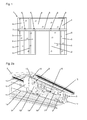
- a sliding door system 1 is shown in a schematic front view.
- the sliding door system 1 has two sliding panels 2 movable in opposite directions, the passage area of which is delimited laterally by a respective fixed field 3.
- a latch 5 which is part of a mullion-transom construction and is supported on a plurality of posts 6.
- a guide rail 7 is arranged, in which the sliding sash 2 are guided by roller carriage 8 slidably.
- the upper portion of the sliding door system 1 is formed by a plurality of skylights 4.
- a drive device not shown here.
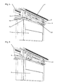
- the Fig. 2 shows in two views ( Fig. 2a and 2 B ), the guide rail 7 of the sliding door system 1 with two already inserted roller carriage 8, but even before the assembly of the sliding leaf 2.
- the profile of the guide rail 7 has an integrally formed, horizontal leg with a running rail 10 on which the rollers 9 of the roller carriage 8 roll ,
- the surface of the running rail 10 is convex shaped, and the running surfaces of the rollers 9 have correspondingly a complementary, concave cross-section.
- the rollers 9 and / or the running rail 10 may also have other, for a safe guidance of the rollers 9 suitable cross-sections.
- the roller carriage 8 also each have support rollers 11 which are intended to prevent jumping out of the rollers 9 of the running rail 10 and this roll on top of support surfaces 12, which are integrally formed on an upper horizontal leg of the guide rail.
- the roller carriage 8 also each comprise a bearing element 13 for supporting the axes of rotation of the rollers 9 and support rollers 11, which is connected via a connecting element 15 with a suspension element 14.
- the bearing element 13, the connecting element 15 and the suspension element 14 may also be formed in one piece.
- the suspension element 14 has means for connecting the sliding leaf 2, in this embodiment bores, which are penetrated by fastening screws for coupling the sliding leaf 2 can be.
- the two roller carriages 8 of a sliding leaf 2 are connected to each other in this embodiment by a coupling element 16.
- the roller carriage 8 may be formed separately from each other.
- roller carriage 8 To insert the already interconnected by the coupling element 16 roller carriage 8 in the guide rail 7, these can be tilted brought from obliquely down to the guide rail 7. After placing the running surfaces of the rollers 9 on the guide rail 10, the roller carriage 8 can then be pivoted in its final orientation upwards until the support rollers 11 are located below the support surfaces 12. In the illustrated mounting state, the roller carriages 8 are already inserted into the guide rail 7 in final alignment, i. the running surfaces of the rollers 9 and the support rollers 11 are in contact with the guide rail 10 and the support surfaces 12, respectively. In order to fix the roller carriage 8 in this intended position, a mounting aid 17 is then brought to this provided receiving areas 18, 19 of the guide rail 7 and the roller carriage 8. In the specific embodiment of the roller carriage 8 associated receiving area 19 is formed on the coupling element 16. The receiving areas 18, 19 are each formed as grooves, in which corresponding mounting portions 22, 23 of the auxiliary assembly 17 can engage.
- the two mounting areas 22, 23 are formed by a plate-shaped element, wherein one mounting area 22 has rounded edges 24 at the end and the other mounting area 23 has edges 25 at the end. Centered and perpendicular to the two mounting portions 22, 23 of the plate-shaped handle portion 21 is arranged.
- the auxiliary assembly device 17 has already been brought into tilted alignment with its mounting areas 22, 23 on the receiving areas 18, 19 of the guide rail 7 or the roller carriage 8, so that a rounding 24 of the upper mounting area 24 into the receiving area 18 of the guide rail 7 and an edge 25 of the lower mounting portion 25 projects into the receiving area 19 of the roller carriage 8.
- the person performing the installation can thus now release the roller carriage 8 fixed by the auxiliary installation device 17 and move the sliding panel 2 to the roller carriage 8, wherein the sliding panel 2 has a suspension element 20 for each roller carriage 8, each under the suspension element 14 of the corresponding roller carriage 8 is positioned and then a connection between the suspension elements 14, 20, for example by screws, is made.
- This mounting condition is in the Fig. 5 shown.
- the roller carriages 8 are now held in their alignment by the sliding leaf 2, ie the auxiliary assembly device 17 can now be re-rotated on the gripping device 21 with its mounting areas 22, 23 from the receiving areas 18, 19 Guide rail 7 and the roller carriage 8 are unscrewed and then removed.
- the then reached mounting state is in the Fig. 6 shown.
- the auxiliary assembly device 17 with respect to the configuration of its handle portion 21 and / or its mounting portions 22, 23 may be deviating, with the receiving areas 18, 19 of the guide rail 7 and the roller carriage 8 may be designed correspondingly different. It is essential that the assembly aid 17 tool-free, that can establish the fixation of the roller carriage 8 on the guide rail 7 by shifting their orientation.
Landscapes
- Engineering & Computer Science (AREA)
- Mechanical Engineering (AREA)
- Support Devices For Sliding Doors (AREA)
Applications Claiming Priority (1)
| Application Number | Priority Date | Filing Date | Title |
|---|---|---|---|
| DE201010030258 DE102010030258B3 (de) | 2010-06-18 | 2010-06-18 | Schiebetüranlage sowie Verfahren zur Montage einer Schiebetüranlage |
Publications (2)
| Publication Number | Publication Date |
|---|---|
| EP2397631A2 true EP2397631A2 (fr) | 2011-12-21 |
| EP2397631A3 EP2397631A3 (fr) | 2014-08-20 |
Family
ID=44484028
Family Applications (1)
| Application Number | Title | Priority Date | Filing Date |
|---|---|---|---|
| EP11169213.3A Ceased EP2397631A3 (fr) | 2010-06-18 | 2011-06-09 | Installation de porte coulissante et procédé de montage d'une installation de porte coulissante |
Country Status (2)
| Country | Link |
|---|---|
| EP (1) | EP2397631A3 (fr) |
| DE (1) | DE102010030258B3 (fr) |
Cited By (1)
| Publication number | Priority date | Publication date | Assignee | Title |
|---|---|---|---|---|
| DE102016217185A1 (de) | 2016-09-09 | 2018-03-15 | Roto Frank Ag | Arretierlehre zur Montage eines Schiebefensters oder einer Schiebetür |
Families Citing this family (1)
| Publication number | Priority date | Publication date | Assignee | Title |
|---|---|---|---|---|
| CN112218454A (zh) * | 2020-10-20 | 2021-01-12 | 华能青岛热电有限公司 | 一种zh-bfk型模块式变压器风冷智能控制柜 |
Citations (2)
| Publication number | Priority date | Publication date | Assignee | Title |
|---|---|---|---|---|
| DE19539956C2 (de) | 1995-10-26 | 1998-05-28 | Tuerautomation Fehraltorf Ag F | Laufschienenanordnung, insbesondere für eine automatische Schiebetür mit mindestens einem Flügel |
| US20090145039A1 (en) * | 2007-11-14 | 2009-06-11 | Maax Bath Inc. | Anti-derailing clip for track mounted doors |
Family Cites Families (3)
| Publication number | Priority date | Publication date | Assignee | Title |
|---|---|---|---|---|
| US6983512B2 (en) * | 2002-07-23 | 2006-01-10 | Masco Corporation | Movable door mounting assembly with trolley locking structure |
| DE202004001068U1 (de) * | 2004-01-23 | 2004-03-18 | Hettich-Heinze Gmbh & Co. Kg | Durch Einklipsen montierbares Laufwerkgehäuse für Schiebe- und Faltschiebetüren |
| DE202008005264U1 (de) * | 2008-04-17 | 2009-09-03 | Hettich-Heinze Gmbh & Co. Kg | Anschlag für ein Möbel |
-
2010
- 2010-06-18 DE DE201010030258 patent/DE102010030258B3/de active Active
-
2011
- 2011-06-09 EP EP11169213.3A patent/EP2397631A3/fr not_active Ceased
Patent Citations (2)
| Publication number | Priority date | Publication date | Assignee | Title |
|---|---|---|---|---|
| DE19539956C2 (de) | 1995-10-26 | 1998-05-28 | Tuerautomation Fehraltorf Ag F | Laufschienenanordnung, insbesondere für eine automatische Schiebetür mit mindestens einem Flügel |
| US20090145039A1 (en) * | 2007-11-14 | 2009-06-11 | Maax Bath Inc. | Anti-derailing clip for track mounted doors |
Cited By (2)
| Publication number | Priority date | Publication date | Assignee | Title |
|---|---|---|---|---|
| DE102016217185A1 (de) | 2016-09-09 | 2018-03-15 | Roto Frank Ag | Arretierlehre zur Montage eines Schiebefensters oder einer Schiebetür |
| DE102016217185B4 (de) | 2016-09-09 | 2026-03-26 | Roto Frank Ag | Montageanordnung mit einer Arretierlehre zur Montage eines Schiebefensters oder einer Schiebetür, Verwendung der Lehre und Verfahren zur Montage der Montageanordnung |
Also Published As
| Publication number | Publication date |
|---|---|
| DE102010030258B3 (de) | 2011-11-17 |
| EP2397631A3 (fr) | 2014-08-20 |
Similar Documents
| Publication | Publication Date | Title |
|---|---|---|
| EP2815136B2 (fr) | Système de montage | |
| AT519903B1 (de) | Schiene zur Führung eines Schlittens einer Möbeltüre | |
| DE102009046944A1 (de) | Montagesystem und Verfahren zur Montage einer Trennwand an eine Halteeinrichtung sowie Vorrichtung zum Trennen von Bereichen | |
| EP2159345B1 (fr) | Fixation pour éléments de revêtement | |
| DE102008026498A1 (de) | Befestigung von Solarmodulen auf Baukörpern | |
| EP0760880B1 (fr) | Dispositif de fixation d'un chassis au profile d'un troncon de rail pose | |
| DE3517443A1 (de) | Haltekonstruktion fuer hinterlueftete fassaden aus schalenfoermigen fassadenelementen | |
| EP2522800A2 (fr) | Agencement de porte coulissante | |
| EP3045638B1 (fr) | Système de battant coulissant et rotatif | |
| DE3238204A1 (de) | Vorrichtung zur haengenden anbringung von scheiben an einer laufschiene | |
| EP3295849B1 (fr) | Pince de porte de douche pour un système de porte coulissante de douche, composant connecté et procédé de couplage de la pince de porte de douche au moyen d'un chariot | |
| DE102016115404A1 (de) | System zur Festlegung wenigstens eines Wandverkleidungsteils | |
| DE102010030258B3 (de) | Schiebetüranlage sowie Verfahren zur Montage einer Schiebetüranlage | |
| DE202010004194U1 (de) | Hinterlüftetes Fassadensystem | |
| WO2014095389A1 (fr) | Système de porte | |
| DE102004003861B4 (de) | Vorrichtung zur lösbaren Halterung von einem Flächenelement, ein System mit wenigstens zwei solcher Vorrichtungen und deren Verwendung | |
| EP0033856A1 (fr) | Support pour la fixation de rails porteurs | |
| DE202010014922U1 (de) | Befestigung einer Antriebsschiene oder eines Antriebsschienenabschnittes mit einem Antriebskopf eines automatisierten Tores oder dergleichen | |
| DE202019102112U1 (de) | Profileinheit zur Rollladenführung und Befestigung wenigstens eines Absturzsicherungselements an einem Blendrahmen oder Pfosten eines Fensters | |
| AT517283B1 (de) | Duschabtrennung mit Schiebetüre und Führungselement | |
| EP2927390B1 (fr) | Dispositif de maintien de façades | |
| DE102008030319B4 (de) | Schiebetüranlage | |
| DE102015103814B4 (de) | Anordnung, System und Verfahren zur Montage für ein Fahrzeugdach | |
| WO2016004966A1 (fr) | Ensemble de rails de guidage et porte sectionnelle | |
| AT13746U1 (de) | Galerie-Vorhangschiene |
Legal Events
| Date | Code | Title | Description |
|---|---|---|---|
| AK | Designated contracting states |
Kind code of ref document: A2 Designated state(s): AL AT BE BG CH CY CZ DE DK EE ES FI FR GB GR HR HU IE IS IT LI LT LU LV MC MK MT NL NO PL PT RO RS SE SI SK SM TR |
|
| AX | Request for extension of the european patent |
Extension state: BA ME |
|
| PUAI | Public reference made under article 153(3) epc to a published international application that has entered the european phase |
Free format text: ORIGINAL CODE: 0009012 |
|
| PUAL | Search report despatched |
Free format text: ORIGINAL CODE: 0009013 |
|
| AK | Designated contracting states |
Kind code of ref document: A3 Designated state(s): AL AT BE BG CH CY CZ DE DK EE ES FI FR GB GR HR HU IE IS IT LI LT LU LV MC MK MT NL NO PL PT RO RS SE SI SK SM TR |
|
| AX | Request for extension of the european patent |
Extension state: BA ME |
|
| RIC1 | Information provided on ipc code assigned before grant |
Ipc: E05D 15/06 20060101AFI20140714BHEP |
|
| 17P | Request for examination filed |
Effective date: 20150217 |
|
| RBV | Designated contracting states (corrected) |
Designated state(s): AL AT BE BG CH CY CZ DE DK EE ES FI FR GB GR HR HU IE IS IT LI LT LU LV MC MK MT NL NO PL PT RO RS SE SI SK SM TR |
|
| 17Q | First examination report despatched |
Effective date: 20150717 |
|
| STAA | Information on the status of an ep patent application or granted ep patent |
Free format text: STATUS: THE APPLICATION HAS BEEN REFUSED |
|
| 18R | Application refused |
Effective date: 20160326 |