EP2396582B1 - Procédé de fabrication de modules d'irradiation - Google Patents
Procédé de fabrication de modules d'irradiation Download PDFInfo
- Publication number
- EP2396582B1 EP2396582B1 EP10702626.2A EP10702626A EP2396582B1 EP 2396582 B1 EP2396582 B1 EP 2396582B1 EP 10702626 A EP10702626 A EP 10702626A EP 2396582 B1 EP2396582 B1 EP 2396582B1
- Authority
- EP
- European Patent Office
- Prior art keywords
- hollow cylinder
- profiled
- gripping
- tube
- irradiation
- Prior art date
- Legal status (The legal status is an assumption and is not a legal conclusion. Google has not performed a legal analysis and makes no representation as to the accuracy of the status listed.)
- Active
Links
- 230000005855 radiation Effects 0.000 title description 31
- 238000004519 manufacturing process Methods 0.000 title description 8
- 238000000034 method Methods 0.000 claims description 46
- 230000002040 relaxant effect Effects 0.000 claims 1
- 239000012530 fluid Substances 0.000 description 18
- 239000000463 material Substances 0.000 description 14
- 230000006378 damage Effects 0.000 description 12
- 238000004804 winding Methods 0.000 description 10
- 241000700605 Viruses Species 0.000 description 9
- 238000009826 distribution Methods 0.000 description 9
- 230000005670 electromagnetic radiation Effects 0.000 description 8
- 239000007788 liquid Substances 0.000 description 8
- 239000000047 product Substances 0.000 description 8
- 238000004659 sterilization and disinfection Methods 0.000 description 8
- 244000005700 microbiome Species 0.000 description 7
- 229920001343 polytetrafluoroethylene Polymers 0.000 description 7
- 239000004810 polytetrafluoroethylene Substances 0.000 description 7
- 230000001954 sterilising effect Effects 0.000 description 7
- 239000011521 glass Substances 0.000 description 6
- 238000003780 insertion Methods 0.000 description 6
- 230000037431 insertion Effects 0.000 description 6
- VYPSYNLAJGMNEJ-UHFFFAOYSA-N Silicium dioxide Chemical compound O=[Si]=O VYPSYNLAJGMNEJ-UHFFFAOYSA-N 0.000 description 5
- 239000004033 plastic Substances 0.000 description 5
- 229920003023 plastic Polymers 0.000 description 5
- 244000089486 Phragmites australis subsp australis Species 0.000 description 4
- 230000007423 decrease Effects 0.000 description 4
- 238000013461 design Methods 0.000 description 4
- 230000002779 inactivation Effects 0.000 description 4
- 239000002245 particle Substances 0.000 description 4
- 206010016352 Feeling of relaxation Diseases 0.000 description 3
- 229960000074 biopharmaceutical Drugs 0.000 description 3
- 238000006243 chemical reaction Methods 0.000 description 3
- 235000013305 food Nutrition 0.000 description 3
- 238000011194 good manufacturing practice Methods 0.000 description 3
- 238000010438 heat treatment Methods 0.000 description 3
- 206010073306 Exposure to radiation Diseases 0.000 description 2
- 238000005299 abrasion Methods 0.000 description 2
- 238000005516 engineering process Methods 0.000 description 2
- 230000000415 inactivating effect Effects 0.000 description 2
- 239000000314 lubricant Substances 0.000 description 2
- 239000002184 metal Substances 0.000 description 2
- 210000002381 plasma Anatomy 0.000 description 2
- 238000002360 preparation method Methods 0.000 description 2
- 102000004169 proteins and genes Human genes 0.000 description 2
- 108090000623 proteins and genes Proteins 0.000 description 2
- 239000000126 substance Substances 0.000 description 2
- 241001136792 Alle Species 0.000 description 1
- 208000034656 Contusions Diseases 0.000 description 1
- 241001465754 Metazoa Species 0.000 description 1
- 239000013543 active substance Substances 0.000 description 1
- 239000012431 aqueous reaction media Substances 0.000 description 1
- 244000052616 bacterial pathogen Species 0.000 description 1
- 239000011324 bead Substances 0.000 description 1
- 238000005452 bending Methods 0.000 description 1
- 239000012620 biological material Substances 0.000 description 1
- 230000015572 biosynthetic process Effects 0.000 description 1
- 239000000919 ceramic Substances 0.000 description 1
- 238000004140 cleaning Methods 0.000 description 1
- 239000011248 coating agent Substances 0.000 description 1
- 238000000576 coating method Methods 0.000 description 1
- 230000000295 complement effect Effects 0.000 description 1
- 239000002131 composite material Substances 0.000 description 1
- 238000011109 contamination Methods 0.000 description 1
- 238000010924 continuous production Methods 0.000 description 1
- 230000001276 controlling effect Effects 0.000 description 1
- 238000007599 discharging Methods 0.000 description 1
- 230000035622 drinking Effects 0.000 description 1
- 239000003651 drinking water Substances 0.000 description 1
- 229940079593 drug Drugs 0.000 description 1
- 239000003814 drug Substances 0.000 description 1
- 238000010616 electrical installation Methods 0.000 description 1
- 238000009730 filament winding Methods 0.000 description 1
- 235000015203 fruit juice Nutrition 0.000 description 1
- 230000001678 irradiating effect Effects 0.000 description 1
- 239000007769 metal material Substances 0.000 description 1
- 230000000813 microbial effect Effects 0.000 description 1
- 235000013336 milk Nutrition 0.000 description 1
- 239000008267 milk Substances 0.000 description 1
- 210000004080 milk Anatomy 0.000 description 1
- 230000035515 penetration Effects 0.000 description 1
- 230000002093 peripheral effect Effects 0.000 description 1
- 239000000825 pharmaceutical preparation Substances 0.000 description 1
- 229940127557 pharmaceutical product Drugs 0.000 description 1
- -1 polytetrafluoroethylene Polymers 0.000 description 1
- 239000012460 protein solution Substances 0.000 description 1
- 239000010453 quartz Substances 0.000 description 1
- 239000012429 reaction media Substances 0.000 description 1
- 230000001105 regulatory effect Effects 0.000 description 1
- 230000002787 reinforcement Effects 0.000 description 1
- 238000007789 sealing Methods 0.000 description 1
- 239000000243 solution Substances 0.000 description 1
- 229910001220 stainless steel Inorganic materials 0.000 description 1
- 239000010935 stainless steel Substances 0.000 description 1
- BFKJFAAPBSQJPD-UHFFFAOYSA-N tetrafluoroethene Chemical group FC(F)=C(F)F BFKJFAAPBSQJPD-UHFFFAOYSA-N 0.000 description 1
- 238000012546 transfer Methods 0.000 description 1
- 230000009261 transgenic effect Effects 0.000 description 1
- 229960005486 vaccine Drugs 0.000 description 1
- 238000010200 validation analysis Methods 0.000 description 1
- 239000002351 wastewater Substances 0.000 description 1
- 239000002023 wood Substances 0.000 description 1
Images


Classifications
-
- B—PERFORMING OPERATIONS; TRANSPORTING
- B23—MACHINE TOOLS; METAL-WORKING NOT OTHERWISE PROVIDED FOR
- B23P—METAL-WORKING NOT OTHERWISE PROVIDED FOR; COMBINED OPERATIONS; UNIVERSAL MACHINE TOOLS
- B23P19/00—Machines for simply fitting together or separating metal parts or objects, or metal and non-metal parts, whether or not involving some deformation; Tools or devices therefor so far as not provided for in other classes
- B23P19/02—Machines for simply fitting together or separating metal parts or objects, or metal and non-metal parts, whether or not involving some deformation; Tools or devices therefor so far as not provided for in other classes for connecting objects by press fit or for detaching same
-
- F—MECHANICAL ENGINEERING; LIGHTING; HEATING; WEAPONS; BLASTING
- F16—ENGINEERING ELEMENTS AND UNITS; GENERAL MEASURES FOR PRODUCING AND MAINTAINING EFFECTIVE FUNCTIONING OF MACHINES OR INSTALLATIONS; THERMAL INSULATION IN GENERAL
- F16L—PIPES; JOINTS OR FITTINGS FOR PIPES; SUPPORTS FOR PIPES, CABLES OR PROTECTIVE TUBING; MEANS FOR THERMAL INSULATION IN GENERAL
- F16L11/00—Hoses, i.e. flexible pipes
- F16L11/04—Hoses, i.e. flexible pipes made of rubber or flexible plastics
- F16L11/11—Hoses, i.e. flexible pipes made of rubber or flexible plastics with corrugated wall
- F16L11/118—Hoses, i.e. flexible pipes made of rubber or flexible plastics with corrugated wall having arrangements for particular purposes, e.g. electrically conducting
-
- A—HUMAN NECESSITIES
- A61—MEDICAL OR VETERINARY SCIENCE; HYGIENE
- A61L—METHODS OR APPARATUS FOR STERILISING MATERIALS OR OBJECTS IN GENERAL; DISINFECTION, STERILISATION OR DEODORISATION OF AIR; CHEMICAL ASPECTS OF BANDAGES, DRESSINGS, ABSORBENT PADS OR SURGICAL ARTICLES; MATERIALS FOR BANDAGES, DRESSINGS, ABSORBENT PADS OR SURGICAL ARTICLES
- A61L2/00—Methods or apparatus for disinfecting or sterilising materials or objects other than foodstuffs or contact lenses; Accessories therefor
- A61L2/02—Methods or apparatus for disinfecting or sterilising materials or objects other than foodstuffs or contact lenses; Accessories therefor using physical phenomena
- A61L2/08—Radiation
- A61L2/10—Ultraviolet radiation
-
- B—PERFORMING OPERATIONS; TRANSPORTING
- B01—PHYSICAL OR CHEMICAL PROCESSES OR APPARATUS IN GENERAL
- B01J—CHEMICAL OR PHYSICAL PROCESSES, e.g. CATALYSIS OR COLLOID CHEMISTRY; THEIR RELEVANT APPARATUS
- B01J19/00—Chemical, physical or physico-chemical processes in general; Their relevant apparatus
- B01J19/08—Processes employing the direct application of electric or wave energy, or particle radiation; Apparatus therefor
- B01J19/12—Processes employing the direct application of electric or wave energy, or particle radiation; Apparatus therefor employing electromagnetic waves
- B01J19/122—Incoherent waves
- B01J19/123—Ultraviolet light
-
- B—PERFORMING OPERATIONS; TRANSPORTING
- B01—PHYSICAL OR CHEMICAL PROCESSES OR APPARATUS IN GENERAL
- B01J—CHEMICAL OR PHYSICAL PROCESSES, e.g. CATALYSIS OR COLLOID CHEMISTRY; THEIR RELEVANT APPARATUS
- B01J19/00—Chemical, physical or physico-chemical processes in general; Their relevant apparatus
- B01J19/24—Stationary reactors without moving elements inside
- B01J19/2415—Tubular reactors
- B01J19/242—Tubular reactors in series
-
- B—PERFORMING OPERATIONS; TRANSPORTING
- B29—WORKING OF PLASTICS; WORKING OF SUBSTANCES IN A PLASTIC STATE IN GENERAL
- B29C—SHAPING OR JOINING OF PLASTICS; SHAPING OF MATERIAL IN A PLASTIC STATE, NOT OTHERWISE PROVIDED FOR; AFTER-TREATMENT OF THE SHAPED PRODUCTS, e.g. REPAIRING
- B29C65/00—Joining or sealing of preformed parts, e.g. welding of plastics materials; Apparatus therefor
- B29C65/66—Joining or sealing of preformed parts, e.g. welding of plastics materials; Apparatus therefor by liberation of internal stresses, e.g. shrinking of one of the parts to be joined
-
- B—PERFORMING OPERATIONS; TRANSPORTING
- B29—WORKING OF PLASTICS; WORKING OF SUBSTANCES IN A PLASTIC STATE IN GENERAL
- B29C—SHAPING OR JOINING OF PLASTICS; SHAPING OF MATERIAL IN A PLASTIC STATE, NOT OTHERWISE PROVIDED FOR; AFTER-TREATMENT OF THE SHAPED PRODUCTS, e.g. REPAIRING
- B29C66/00—General aspects of processes or apparatus for joining preformed parts
- B29C66/01—General aspects dealing with the joint area or with the area to be joined
- B29C66/05—Particular design of joint configurations
- B29C66/10—Particular design of joint configurations particular design of the joint cross-sections
- B29C66/11—Joint cross-sections comprising a single joint-segment, i.e. one of the parts to be joined comprising a single joint-segment in the joint cross-section
- B29C66/112—Single lapped joints
- B29C66/1122—Single lap to lap joints, i.e. overlap joints
-
- B—PERFORMING OPERATIONS; TRANSPORTING
- B29—WORKING OF PLASTICS; WORKING OF SUBSTANCES IN A PLASTIC STATE IN GENERAL
- B29C—SHAPING OR JOINING OF PLASTICS; SHAPING OF MATERIAL IN A PLASTIC STATE, NOT OTHERWISE PROVIDED FOR; AFTER-TREATMENT OF THE SHAPED PRODUCTS, e.g. REPAIRING
- B29C66/00—General aspects of processes or apparatus for joining preformed parts
- B29C66/50—General aspects of joining tubular articles; General aspects of joining long products, i.e. bars or profiled elements; General aspects of joining single elements to tubular articles, hollow articles or bars; General aspects of joining several hollow-preforms to form hollow or tubular articles
- B29C66/51—Joining tubular articles, profiled elements or bars; Joining single elements to tubular articles, hollow articles or bars; Joining several hollow-preforms to form hollow or tubular articles
- B29C66/52—Joining tubular articles, bars or profiled elements
- B29C66/522—Joining tubular articles
- B29C66/5227—Joining tubular articles for forming multi-tubular articles by longitudinally joining elementary tubular articles wall-to-wall (e.g. joining the wall of a first tubular article to the wall of a second tubular article) or for forming multilayer tubular articles
- B29C66/52271—Joining tubular articles for forming multi-tubular articles by longitudinally joining elementary tubular articles wall-to-wall (e.g. joining the wall of a first tubular article to the wall of a second tubular article) or for forming multilayer tubular articles one tubular article being placed inside the other
- B29C66/52272—Joining tubular articles for forming multi-tubular articles by longitudinally joining elementary tubular articles wall-to-wall (e.g. joining the wall of a first tubular article to the wall of a second tubular article) or for forming multilayer tubular articles one tubular article being placed inside the other concentrically, e.g. for forming multilayer tubular articles
-
- B—PERFORMING OPERATIONS; TRANSPORTING
- B29—WORKING OF PLASTICS; WORKING OF SUBSTANCES IN A PLASTIC STATE IN GENERAL
- B29C—SHAPING OR JOINING OF PLASTICS; SHAPING OF MATERIAL IN A PLASTIC STATE, NOT OTHERWISE PROVIDED FOR; AFTER-TREATMENT OF THE SHAPED PRODUCTS, e.g. REPAIRING
- B29C66/00—General aspects of processes or apparatus for joining preformed parts
- B29C66/50—General aspects of joining tubular articles; General aspects of joining long products, i.e. bars or profiled elements; General aspects of joining single elements to tubular articles, hollow articles or bars; General aspects of joining several hollow-preforms to form hollow or tubular articles
- B29C66/51—Joining tubular articles, profiled elements or bars; Joining single elements to tubular articles, hollow articles or bars; Joining several hollow-preforms to form hollow or tubular articles
- B29C66/53—Joining single elements to tubular articles, hollow articles or bars
- B29C66/532—Joining single elements to the wall of tubular articles, hollow articles or bars
- B29C66/5324—Joining single elements to the wall of tubular articles, hollow articles or bars said single elements being substantially annular, i.e. of finite length
- B29C66/53241—Joining single elements to the wall of tubular articles, hollow articles or bars said single elements being substantially annular, i.e. of finite length said articles being tubular and said substantially annular single elements being of finite length relative to the infinite length of said tubular articles
-
- B—PERFORMING OPERATIONS; TRANSPORTING
- B29—WORKING OF PLASTICS; WORKING OF SUBSTANCES IN A PLASTIC STATE IN GENERAL
- B29C—SHAPING OR JOINING OF PLASTICS; SHAPING OF MATERIAL IN A PLASTIC STATE, NOT OTHERWISE PROVIDED FOR; AFTER-TREATMENT OF THE SHAPED PRODUCTS, e.g. REPAIRING
- B29C66/00—General aspects of processes or apparatus for joining preformed parts
- B29C66/70—General aspects of processes or apparatus for joining preformed parts characterised by the composition, physical properties or the structure of the material of the parts to be joined; Joining with non-plastics material
- B29C66/74—Joining plastics material to non-plastics material
- B29C66/746—Joining plastics material to non-plastics material to inorganic materials not provided for in groups B29C66/742 - B29C66/744
- B29C66/7465—Glass
-
- F—MECHANICAL ENGINEERING; LIGHTING; HEATING; WEAPONS; BLASTING
- F16—ENGINEERING ELEMENTS AND UNITS; GENERAL MEASURES FOR PRODUCING AND MAINTAINING EFFECTIVE FUNCTIONING OF MACHINES OR INSTALLATIONS; THERMAL INSULATION IN GENERAL
- F16L—PIPES; JOINTS OR FITTINGS FOR PIPES; SUPPORTS FOR PIPES, CABLES OR PROTECTIVE TUBING; MEANS FOR THERMAL INSULATION IN GENERAL
- F16L11/00—Hoses, i.e. flexible pipes
- F16L11/04—Hoses, i.e. flexible pipes made of rubber or flexible plastics
- F16L11/11—Hoses, i.e. flexible pipes made of rubber or flexible plastics with corrugated wall
- F16L11/118—Hoses, i.e. flexible pipes made of rubber or flexible plastics with corrugated wall having arrangements for particular purposes, e.g. electrically conducting
- F16L11/1185—Hoses, i.e. flexible pipes made of rubber or flexible plastics with corrugated wall having arrangements for particular purposes, e.g. electrically conducting electrically conducting
-
- F—MECHANICAL ENGINEERING; LIGHTING; HEATING; WEAPONS; BLASTING
- F16—ENGINEERING ELEMENTS AND UNITS; GENERAL MEASURES FOR PRODUCING AND MAINTAINING EFFECTIVE FUNCTIONING OF MACHINES OR INSTALLATIONS; THERMAL INSULATION IN GENERAL
- F16L—PIPES; JOINTS OR FITTINGS FOR PIPES; SUPPORTS FOR PIPES, CABLES OR PROTECTIVE TUBING; MEANS FOR THERMAL INSULATION IN GENERAL
- F16L11/00—Hoses, i.e. flexible pipes
- F16L11/04—Hoses, i.e. flexible pipes made of rubber or flexible plastics
- F16L11/12—Hoses, i.e. flexible pipes made of rubber or flexible plastics with arrangements for particular purposes, e.g. specially profiled, with protecting layer, heated, electrically conducting
-
- F—MECHANICAL ENGINEERING; LIGHTING; HEATING; WEAPONS; BLASTING
- F16—ENGINEERING ELEMENTS AND UNITS; GENERAL MEASURES FOR PRODUCING AND MAINTAINING EFFECTIVE FUNCTIONING OF MACHINES OR INSTALLATIONS; THERMAL INSULATION IN GENERAL
- F16L—PIPES; JOINTS OR FITTINGS FOR PIPES; SUPPORTS FOR PIPES, CABLES OR PROTECTIVE TUBING; MEANS FOR THERMAL INSULATION IN GENERAL
- F16L11/00—Hoses, i.e. flexible pipes
- F16L11/20—Double-walled hoses, i.e. two concentric hoses
-
- B—PERFORMING OPERATIONS; TRANSPORTING
- B01—PHYSICAL OR CHEMICAL PROCESSES OR APPARATUS IN GENERAL
- B01J—CHEMICAL OR PHYSICAL PROCESSES, e.g. CATALYSIS OR COLLOID CHEMISTRY; THEIR RELEVANT APPARATUS
- B01J2219/00—Chemical, physical or physico-chemical processes in general; Their relevant apparatus
- B01J2219/00002—Chemical plants
- B01J2219/00018—Construction aspects
- B01J2219/0002—Plants assembled from modules joined together
-
- B—PERFORMING OPERATIONS; TRANSPORTING
- B29—WORKING OF PLASTICS; WORKING OF SUBSTANCES IN A PLASTIC STATE IN GENERAL
- B29C—SHAPING OR JOINING OF PLASTICS; SHAPING OF MATERIAL IN A PLASTIC STATE, NOT OTHERWISE PROVIDED FOR; AFTER-TREATMENT OF THE SHAPED PRODUCTS, e.g. REPAIRING
- B29C66/00—General aspects of processes or apparatus for joining preformed parts
- B29C66/70—General aspects of processes or apparatus for joining preformed parts characterised by the composition, physical properties or the structure of the material of the parts to be joined; Joining with non-plastics material
- B29C66/71—General aspects of processes or apparatus for joining preformed parts characterised by the composition, physical properties or the structure of the material of the parts to be joined; Joining with non-plastics material characterised by the composition of the plastics material of the parts to be joined
-
- B—PERFORMING OPERATIONS; TRANSPORTING
- B29—WORKING OF PLASTICS; WORKING OF SUBSTANCES IN A PLASTIC STATE IN GENERAL
- B29L—INDEXING SCHEME ASSOCIATED WITH SUBCLASS B29C, RELATING TO PARTICULAR ARTICLES
- B29L2023/00—Tubular articles
- B29L2023/18—Pleated or corrugated hoses
-
- C—CHEMISTRY; METALLURGY
- C02—TREATMENT OF WATER, WASTE WATER, SEWAGE, OR SLUDGE
- C02F—TREATMENT OF WATER, WASTE WATER, SEWAGE, OR SLUDGE
- C02F1/00—Treatment of water, waste water, or sewage
- C02F1/30—Treatment of water, waste water, or sewage by irradiation
- C02F1/32—Treatment of water, waste water, or sewage by irradiation with ultraviolet light
- C02F1/325—Irradiation devices or lamp constructions
-
- C—CHEMISTRY; METALLURGY
- C02—TREATMENT OF WATER, WASTE WATER, SEWAGE, OR SLUDGE
- C02F—TREATMENT OF WATER, WASTE WATER, SEWAGE, OR SLUDGE
- C02F2201/00—Apparatus for treatment of water, waste water or sewage
- C02F2201/002—Construction details of the apparatus
- C02F2201/004—Seals, connections
-
- Y—GENERAL TAGGING OF NEW TECHNOLOGICAL DEVELOPMENTS; GENERAL TAGGING OF CROSS-SECTIONAL TECHNOLOGIES SPANNING OVER SEVERAL SECTIONS OF THE IPC; TECHNICAL SUBJECTS COVERED BY FORMER USPC CROSS-REFERENCE ART COLLECTIONS [XRACs] AND DIGESTS
- Y10—TECHNICAL SUBJECTS COVERED BY FORMER USPC
- Y10T—TECHNICAL SUBJECTS COVERED BY FORMER US CLASSIFICATION
- Y10T29/00—Metal working
- Y10T29/49—Method of mechanical manufacture
- Y10T29/49826—Assembling or joining
- Y10T29/49863—Assembling or joining with prestressing of part
- Y10T29/49867—Assembling or joining with prestressing of part of skin on frame member
- Y10T29/49869—Assembling or joining with prestressing of part of skin on frame member by flexing
-
- Y—GENERAL TAGGING OF NEW TECHNOLOGICAL DEVELOPMENTS; GENERAL TAGGING OF CROSS-SECTIONAL TECHNOLOGIES SPANNING OVER SEVERAL SECTIONS OF THE IPC; TECHNICAL SUBJECTS COVERED BY FORMER USPC CROSS-REFERENCE ART COLLECTIONS [XRACs] AND DIGESTS
- Y10—TECHNICAL SUBJECTS COVERED BY FORMER USPC
- Y10T—TECHNICAL SUBJECTS COVERED BY FORMER US CLASSIFICATION
- Y10T29/00—Metal working
- Y10T29/49—Method of mechanical manufacture
- Y10T29/49826—Assembling or joining
- Y10T29/49863—Assembling or joining with prestressing of part
- Y10T29/4987—Elastic joining of parts
-
- Y—GENERAL TAGGING OF NEW TECHNOLOGICAL DEVELOPMENTS; GENERAL TAGGING OF CROSS-SECTIONAL TECHNOLOGIES SPANNING OVER SEVERAL SECTIONS OF THE IPC; TECHNICAL SUBJECTS COVERED BY FORMER USPC CROSS-REFERENCE ART COLLECTIONS [XRACs] AND DIGESTS
- Y10—TECHNICAL SUBJECTS COVERED BY FORMER USPC
- Y10T—TECHNICAL SUBJECTS COVERED BY FORMER US CLASSIFICATION
- Y10T29/00—Metal working
- Y10T29/49—Method of mechanical manufacture
- Y10T29/49826—Assembling or joining
- Y10T29/49945—Assembling or joining by driven force fit
-
- Y—GENERAL TAGGING OF NEW TECHNOLOGICAL DEVELOPMENTS; GENERAL TAGGING OF CROSS-SECTIONAL TECHNOLOGIES SPANNING OVER SEVERAL SECTIONS OF THE IPC; TECHNICAL SUBJECTS COVERED BY FORMER USPC CROSS-REFERENCE ART COLLECTIONS [XRACs] AND DIGESTS
- Y10—TECHNICAL SUBJECTS COVERED BY FORMER USPC
- Y10T—TECHNICAL SUBJECTS COVERED BY FORMER US CLASSIFICATION
- Y10T29/00—Metal working
- Y10T29/53—Means to assemble or disassemble
- Y10T29/53987—Tube, sleeve or ferrule
Definitions
- the present invention is an apparatus and a method for applying flexible, profiled hollow cylinder on cylindrical body.
- Profiled hollow cylinders which are applied to a cylindrical body, form modules which are suitable for the irradiation of fluid media with electromagnetic radiation.
- the present invention therefore also provides a process for the production of radiation modules and irradiation modules produced by means of the process according to the invention.
- a cylinder is a body bounded by two parallel, flat surfaces (ground and top surface) and a lateral surface formed by parallel straight lines. It is created by shifting a flat surface or curve along a straight line that is not in this plane.
- a special embodiment of a cylinder is a circular cylinder. It is created by shifting a circle parallel to a straight line through the center of the circle, the line not being in the circle plane.
- a circular cylinder is limited by two parallel circular surfaces (base and top surface) and the so-called lateral surface.
- a hollow cylinder is understood here and below to mean a special embodiment of a cylinder, which is characterized in that a channel runs parallel to the lateral surface from the base surface to the top surface.
- a pipe is an example of a hollow cylinder.
- a flexible hollow cylinder is understood to be a hollow cylinder which can be bent and / or stretched to a certain extent. The degree of stretching and / or bending amounts to at least 1% of the length and / or the diameter of the hollow cylinder.
- An example of a flexible hollow cylinder is a hose.
- a profiled hollow cylinder is understood to mean a hollow cylinder which has a profile along its lateral surface. This profile can eg wavy or be helical.
- profiled hollow cylinders are corrugated hoses and corrugated pipes as well as spiral hoses and helical pipes.
- a flexible profiled hollow cylinder is characterized in that it can be stretched to some extent (at least 1% of the length and / or diameter of the hollow cylinder, preferably 5 to 20%) along its longitudinal axis.
- Corrugated hoses are used in the automotive industry, mechanical and plant engineering as well as in medical technology for the protection and bundling of electrical or other lines as well as for the flexible connection to peripheral devices.
- plastic corrugated tubes are mainly used as or instead of so-called empty conduits both in outdoor areas, but above all within building walls and ceilings.
- Corrugated pipes are used as heat exchangers (for example, stainless steel in buffer tanks or plastic for underfloor heating).
- the corrugated structure serves to enlarge the surface for the best possible heat transfer.
- Corrugated pipe pieces are used to compensate for axial offsets or to compensate for changes in length and angle.
- the profiled wood cylinders are applied to a cylindrical body.
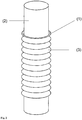
- a so-called irradiation module is described, which is characterized in that a helical tube is applied in a form-fitting manner via an inner support tube. This creates between the support tube and the helical tube, a channel helically from one end of the Spiral hose runs around the support tube to the other end of the spiral tube.
- Such a device is very well suited for the irradiation of fluid media flowing through the channel.
- one or more radiation sources are arranged in the support tube and / or the spiral tube, which irradiate the medium flowing in the channel preferably with UV radiation, particularly preferably with UV-C radiation. Irradiation leads to the reduction of microorganisms and / or viruses or to the chemical reaction in a photochemical reactor
- the distinguishing feature of the flow-through channel is an intensive, uniform over the entire length uniform cross-mixing perpendicular to the main direction of the product flow and a narrowed by turbulent product flow residence time distribution. Cross-mixing ensures that the fluid layers that are more remote from the radiation source and that receive little or no UV radiation, especially in the case of strongly light-absorbing media, undergo an intensive exchange with the UV-irradiated layers near the radiation source.
- This and the narrow residence time distribution mean that all fluid elements experience a uniform and uniform irradiation duration and intensity, which can be adapted to the respective needs by the flow rate and the intensity of the radiation source.
- an effective reduction of microorganisms and / or viruses takes place in the medium.
- the risk that an unfavorably broad residence time distribution leads to excessive exposure to radiation and thus partial damage is effectively reduced.
- the helical tube surrounds the support tube in a form-fitting manner and thus only a single channel is formed, which extends helically around the support tube. Cross flows between adjacent channel windings are to be avoided, as these would lead to a broadening of the residence time distribution.
- the production of the channel takes place in EP-A 1464342 by drawing a coiled hose onto a cylindrical support body.
- a suitable geometry of the relative to the support body in the inner diameter slightly reduced helical tube a tight, non-positive connection between the two elements is produced.
- the axial short-circuit currents otherwise caused by gaps between the channel windings and the associated widening of the residence time distribution can be prevented.
- a profiled hollow cylinder has due to its profiling of the lateral surface a number of bottlenecks (also referred to here as turns), which must be overcome when applied to a cylindrical body.
- the application is usually carried out in such a way that the cylindrical body is inserted into the channel of the profiled hollow cylinder and / or the profiled hollow cylinder is mounted on the cylindrical body.
- the task is to provide a method by which flexible, profiled hollow cylinder can be applied to cylindrical body, without any component in this case takes damage.
- the process sought should be at least partially automated. It should be easy and inexpensive to exercise.
- the task is to provide a device with which the desired method can be exercised.
- the sought device should be intuitive to use and also inexpensive.
- the sought-after method is intended to enable the reproducible production of irradiation devices that have well-defined channel geometries and thus effective and reproducible results in the irradiation of fluid media by means of electromagnetic radiation, for example can hardly prevent gaps between adjacent channel windings. The result is a poorly defined and non-reproducible irradiation device. In addition, too much friction can lead to particle abrasion. These particles are critical for various applications, such as in the pharmaceutical environment.
- DE-A 2061299 relates to a flexible corrugated filament winding tube.
- the flexible thread winding tube can be used in particular as a pipe or hose connector and it is designed so that there is a good sealing connection between two pipes or the like. causes.
- the tube is flexible and can be easily attached and detached, but still has sufficient strength to withstand high internal pressures, external pressures and longitudinal forces.
- the tube or hose is corrugated to ensure flexibility and good strength. Furthermore, the corrugation gives the tube stiffening ribs, so that the bore or the interior of the tube remains sufficiently open when the tube is bent or curved over its length.
- EP-A 1464342 in turn relates to a technique for the safe and gentle UV treatment and heat sterilization of liquid media and in particular microorganisms and / or viruses containing liquids, such as. Food, milk or fruit juice products, chemical or pharmaceutical products, virus vaccines, genetically engineered drugs or Proteins, active substances or proteins from transgenic animals or plants and blood plasma or products derived from blood plasma.
- liquid media such as. Food, milk or fruit juice products, chemical or pharmaceutical products, virus vaccines, genetically engineered drugs or Proteins, active substances or proteins from transgenic animals or plants and blood plasma or products derived from blood plasma.
- EP-A 1464342 is a continuous process for sterilization and optionally virus inactivation fluid, especially aqueous reaction media disclosed by a combined application of a heat and a UV treatment by irradiation, characterized in that the heat treatment of the reaction medium at a sterilization temperature of 40 ° C to 135 ° C and the irradiation at an irradiance of 5 to 300 W / m 2 takes place.
- the task is to provide a method by which flexible, profiled hollow cylinder can be applied to cylindrical body, without any component in this case takes damage.
- the process sought should be at least partially automated. It should be easy and inexpensive to exercise.
- the task is to provide a device with which the desired method can be exercised.
- the sought device should be intuitive to use and also inexpensive.
- the sought-after method is intended to enable the reproducible production of irradiation devices that have well-defined channel geometries and thus effective and reproducible results in the irradiation of fluid media by means of electromagnetic radiation, for example for the purpose of inactivating microorganisms and / or viruses with UV radiation.
- flexible, profiled hollow cylinders can be easily applied to a cylindrical body when the profiled hollow cylinders are elongated along the longitudinal axis (ie axially stretched).
- the present invention is therefore a method according to claim 1.
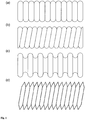
- the inventive method is applicable to flexible, profiled hollow cylinder whose profiling at least partially in the form of waves or grooves, which do not extend in the direction of the longitudinal axis. Examples of such flexible, profiled hollow cylinders are in FIG. 1 shown schematically. Further profiles are conceivable.
- the elongation of the hollow cylinder means that the hollow cylinder is stretched along its longitudinal axis, so that its length increases.
- the degree of elongation is from 1% to 30%, preferably from 5% to 20%, particularly preferably from 10 to 15%, so that the length of the hollow cylinder increases by the stated percentage.
- the smallest inner diameter of the hollow cylinder which is formed by the turns / constrictions of the profiling, increases as a result of an elongation according to the invention. If elongation exceeds a threshold, the smallest diameter may decrease again.
- the threshold value depends on the material and the profiling. The threshold can easily be determined empirically.
- the elongation of the invention in step (a) is not longer than two minutes, when the elongated hollow cylinder made of PTFE (polytetrafluoroethylene) and at room temperature (15 ° C to 25 ° C) is processed.
- PTFE polytetrafluoroethylene
- the elongation of the hollow cylinder according to the invention can be carried out by fixing the hollow cylinder at one end and gripping and stretching it at the other end.
- the hollow cylinder can be hung at one end.
- the own weight of the hollow cylinder already takes a certain lengthening. By applying weights and / or pulling on the other end, the elongation can be increased.
- the cylindrical body can be introduced from above or below in the elongated hollow cylinder.
- the elongation takes place by grasping the hollow cylinder at at least one point, preferably at least two points.
- Preferred locations for grasping the hollow cylinder are the two ends.
- one socket (the first) can be held while the other socket is removed from the first.
- both sockets move away from each other.
- the socket of the hollow cylinders takes place at several points along the hollow cylinder.
- the socket locations are preferably distributed uniformly over the length of the hollow cylinder.
- the optimum number of sockets depends on the length, shape and material of the hollow cylinder and can be determined empirically.
- the distance between two adjacent adjustment points is 300 mm to 500 mm when using a PTFE spiral hose with a diameter of 5 to 20 cm as a profiled hollow cylinder.
- step (b) of the method according to the invention it is irrelevant whether the body is pushed into the hollow cylinder or the hollow cylinder is pulled or pushed onto the body, or if a combination of movements and forces occurs.
- a corresponding device ensures that body and hollow cylinder reach each other in a predetermined position (example see below). If in the following it is said that the hollow cylinder is pulled or pushed onto the body or the body is pushed or pulled into the hollow cylinder, this always means a force and a resulting relative movement between the hollow cylinder and the body meant the hollow cylinder and body in one brings predetermined position to each other.
- step (b) is accomplished using a so-called centering device or introducer.
- the centering device or insertion aid is an attachment which is attached to the end of the cylindrical body with which the body is introduced into the hollow cylinder.
- the body to be introduced has sharp edges which, when the body is introduced into the hollow cylinder, can lead to shavings and / or scratches and / or cuts on the turns / constrictions of the profiling of the hollow cylinder.
- the elongated hollow cylinder can not be aligned in all cases along its entire length along its longitudinal axis. In a horizontal position of the elongated hollow cylinder of the flexible hollow cylinder between two positions, if necessary, a little down.
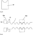
- the cylindrical body to be inserted could encounter windings / bottlenecks during insertion and cause damage. This is effectively prevented by the use of a centering device or insertion aid, which is preferably conical and introduces the Body leads.
- a centering device or insertion aid is shown in FIG FIG. 5 given.
- step (c) the force to elongate the hollow cylinder is released, so that the hollow cylinder relaxes and decreases in length.
- the smallest diameter of the hollow cylinder decreases again by this relaxation and the hollow cylinder encloses the cylindrical body.
- Step (c) takes place as evenly as possible over the entire length of the hollow cylinder, so that no stresses arise within the profiled hollow cylinder.
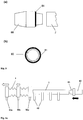
- the hollow cylinder should be uniformly and uniformly applied to the cylindrical body. This is done particularly effectively using so-called Matritzen, which lead the relaxation and facilitate the adjustment between the hollow cylinder and the cylindrical body.
- the matrices have a profile that corresponds to the "negative" of the hollow cylinder profile. This ensures that a maximum contact surface is created and the forces for elongation and adjustment can be uniformly introduced into the profiled hollow cylinder.
- the method according to the invention in a modified form is also suitable for introducing a flexible, profiled hollow cylinder into another hollow cylinder.
- inventive elongation of the profiled hollow cylinder not only its smallest inner diameter increases, but surprisingly also its largest outer diameter. If a flexible, profiled hollow cylinder to be introduced into a hollow cylinder, whose inner diameter is smaller than the largest outer diameter of the profiled hollow cylinder, the introduction can be accomplished by elongation according to the invention simply, with little effort and avoiding damage to the hollow cylinders. The considerations and solutions made here can therefore also be applied to this technical problem.
- An irradiation device is understood to mean a device through which a fluid medium flows, the medium being exposed to electromagnetic radiation.
- UV radiation such an irradiation device can be used e.g. for the reduction of microorganisms and / or viruses in fluid media.
- IR radiation such an irradiation device can be used e.g. to heat a fluid medium.
- Other uses are conceivable, such as reactors for photochemically activated and / or photochemical processes.
- a helical tube is used as the flexible, profiled hollow cylinder.
- the spiral tube is preferably made of a plastic, eg PTFE (perfluoroethylene).
- a tube transparent to electromagnetic radiation is preferably used.
- a quartz glass tube is used, which is transparent to UV radiation.
- the inventive method is particularly suitable for the production of such irradiation devices - hereinafter also called irradiation modules, which are characterized in that a helical tube is mounted on a support tube so that there is an interference fit between the helical tube and the support tube. Under press fit is understood that the smallest inner diameter of the spiral tube in the force-free state is smaller than the outer diameter of the cylindrical body.
- the smallest inner diameter of the helical tube is increased and reaches a value which is greater than the outer diameter of the support tube.
- a simple introduction of the support tube in the helical tube without excessive force application and thus without damaging the tube and the support tube is possible.
- the smallest inner diameter of the hose decreases and the turns of the hose enclose the quartz glass tube in a form-fitting and uniform manner. Due to the interference fit, the windings exert a pressure on the quartz glass, so that the hose can not slip off the quartz glass tube.
- the subject of the present invention is thus also a process for the preparation of radiation modules.
- irradiation modules which have been produced by means of the method according to the invention are the subject of the present invention.
- the radiation modules according to the invention can be e.g. for the irradiation of fluid media for the purpose of sterilization and / or virus inactivation.
- Sterilization or microbial reduction in fluid media is an important step in many processes. Contamination with active, ie reproducible, biological material such as microorganisms or viruses often poses a threat to product safety, which must be effectively counteracted.
- the germ reduction by inactivation with ultraviolet radiation has long been known and is widely practiced. Examples include surface disinfection as well as the treatment of liquid media such as drinking and wastewater.
- An essential technical challenge is given if, in addition to the microorganisms to be inactivated, valuable substances are also contained which, to a certain extent, can also be damaged by the radiation.
- Such requirements are typical for sterilization in the field of food and bio-pharmaceutical liquids, such as protein solutions. Additional difficulties arise when the turbidity of the processed liquid in the range of UV-C radiation high and thus the penetration of the inactivating Radiation is low.
- Such applications call for technical systems which, despite the high turbidity, can achieve homogeneous irradiation, that is to say a narrow dose distribution.
- a certain residence time in the irradiation zone equivalent to irradiation time, is additionally to be provided here.
- the system-specific residence time distribution also leads to a broad, that is to say inhomogeneous, dose distribution in the liquid.
- the radiation module according to the invention for the irradiation of fluids with electromagnetic radiation comprises a UV-transparent tube (cylindrical body) for receiving a centrally arranged, elongate radiation source and a spiral tube (profiled hollow cylinder) applied to the tube, such that between the turning tube and tube depending on Profiling one or more helical channels arise in which a processed fluid, during the residence time in the irradiation zone, can be irradiated.
- a helical channel forces the fluid flowing through into a helical flow.
- the distinguishing feature of the flow-through channel is an intensive, uniform over the entire length uniform (caused by so-called Dean vortex) cross-mixing perpendicular to the main direction of the product flow - even in laminar flow conditions. This ensures that the more distant from the radiation source fluid layers, which receive no or little UV radiation especially in strongly light-absorbing media, undergo an intensive exchange with the UV-irradiated layers near the radiation source.
- Such a channel particularly preferably has a rectangular (preferably with rounded corners), trapezoidal or semicircular cross-sectional profile.
- a channel has a depth of 1 to 100 mm, preferably of 2 to 50 mm, and an average width of 1 to 200 mm, preferably of 2 to 50 mm, in the cross-sectional profile.
- the profiling in a single inside along the lateral surface helically running channel which has a pitch of 2 to 20 ° (pitch angle), preferably from 4 to 10 °.
- the material of the tube, through which the irradiation of the liquid takes place should be largely radiolucent. Suitable materials are, depending on the wavelength range of the electromagnetic radiation, for example, glass or plastics. The material that forms the channel and is not irradiated should be dimensionally stable in particular. Suitable materials are, for example, metallic materials, plastics, ceramics, glass or composite materials. If this material should be at least largely transparent to the electromagnetic radiation used, complementary or alternative irradiation can also take place from outside through this component.
- Another embodiment may be a reflective coating on the inside of the profiled hollow cylinder, so that it comes to a reflection of the radiation and thus to an intensification of the radiation in the irradiation zone.
- the irradiation module according to the invention is produced by applying a spiral tube made of PTFE onto a support tube permeable to UV rays, wherein the smallest inner diameter of the spiral tube, given by the inner turns, is slightly smaller than the outer diameter of the support tube.
- slightly smaller it is understood that the smallest inner diameter of the helical tube by 0.01% to 5%, preferably by 0.1% to 3% smaller than the outer diameter of the support tube.
- the radiation input takes place via an elongated radiation source introduced centrally into the support tube or from the outside with radiation sources arranged around the helical tube.
- irradiation takes place by means of a radiation source mounted inside the support tube.
- the support tube is preferably designed for UV-C treatment as permeable to UV-C rays quartz tube. Since it is difficult to clean the channels because of their poor accessibility, in a preferred embodiment the irradiation modules according to the invention are designed as disposable elements which are packed sterile or with low germs. Disposable systems are particularly popular in the biopharmaceutical industry, as the use of disposable systems saves complex cleaning validations. The requirements of such disposable systems are that they can be produced inexpensively and have a reproducible quality.
- the quality refers in particular to constant dimensioning and consistent surface properties of the support tube (no lubricant, no film, no scratches).
- the irradiation modules according to the invention fulfill these requirements because the method according to the invention for the production of the irradiation modules provides reproducible results, can be automated and thus be carried out on an industrial scale, as well as inexpensive and manages without lubricant.
- the irradiation modules according to the invention furthermore have at least two connections for introducing and discharging a fluid into the helical irradiation space. Examples of how a spiral hose can be provided with connections on a support body can be found in FIG EP 1464342 A1 ,
- the subject of the present invention is also a device for applying flexible, profiled hollow cylinders to cylindrical bodies according to claim 9.
- the device according to the invention has means for mounting a flexible, profiled hollow cylinder at one or more locations, means for elongating the hollow cylinder and means for introducing the body in the profiled hollow cylinder.
- the socket of a hollow cylinder is preferably carried out in at least two places.
- the means for mounting the hollow cylinder (socket elements) hold a hollow cylinder preferably at the ends. In a particularly preferred embodiment, further socket elements are preferably distributed uniformly over the length of the hollow cylinder.
- All socket elements or all socket elements except one are designed to be movable, so that they can be moved against each other after grasping the hollow cylinder and so the hollow cylinder can be stretched (lengthened) along its longitudinal axis.
- the movement of the socket elements is done for example by stepper motors or the like.
- the device according to the invention has position encoders, which can determine the position of each socket element, so that the elongation and / or the adjustment and / or the relaxation runs regulated.
- the means for introducing the cylindrical body in the profiled hollow cylinder for example, consist of a motor-driven push rod, which introduces the example mounted on support elements body in the hollow cylinder.
- the device according to the invention further comprises means for temperature control to ensure constant process conditions. Further, it may be advantageous to heat the profiled hollow cylinder prior to elongation and / or relaxation, e.g. to increase its elasticity and thus prevent damage due to elongation.
- the device according to the invention further comprises means for adjustment between the hollow cylinder and the cylindrical body.
- An example is in FIG. 6c shown.
- the socket elements and / or means for adjustment at the contact point to the hollow cylinder also have a profiled contour corresponding to the negative contour of the profiled hollow cylinder.
- the width of a receptacle should be at least one, preferably two to ten, more preferably two to five profile turns.
- the device according to the invention further comprises means for increasing the internal pressure within the profiled hollow cylinder in order to widen the smallest inner diameter of the profiled hollow cylinder.
- the pressure increase can be carried out in support of the elongation.
- Further features of the device according to the invention are means for controlling the elongation and / or the adjustment of the profiled hollow cylinder and / or the introduction of the cylindrical body in the elongate hollow cylinder.
Landscapes
- Engineering & Computer Science (AREA)
- Mechanical Engineering (AREA)
- General Engineering & Computer Science (AREA)
- Chemical & Material Sciences (AREA)
- Chemical Kinetics & Catalysis (AREA)
- Organic Chemistry (AREA)
- Health & Medical Sciences (AREA)
- General Health & Medical Sciences (AREA)
- Inorganic Chemistry (AREA)
- Toxicology (AREA)
- Electromagnetism (AREA)
- Physics & Mathematics (AREA)
- Animal Behavior & Ethology (AREA)
- Veterinary Medicine (AREA)
- Public Health (AREA)
- Life Sciences & Earth Sciences (AREA)
- Epidemiology (AREA)
- Physical Or Chemical Processes And Apparatus (AREA)
- Materials For Medical Uses (AREA)
- Apparatus For Disinfection Or Sterilisation (AREA)
- Rigid Pipes And Flexible Pipes (AREA)
- Physical Water Treatments (AREA)
- External Artificial Organs (AREA)
- Diaphragms And Bellows (AREA)
Claims (13)
- Procédé pour appliquer un cylindre creux souple et profilé (1) sur un corps cylindrique (2), le procédé comportant au moins les étapes ci-dessous, exécutées dans l'ordre indiqué :(a) allongement du cylindre creux (1) par étirage axial de 1 % à 30 % le long de son axe longitudinal de manière à augmenter le plus petit diamètre intérieur du cylindre creux (1),(b) insertion du corps cylindrique (2) dans le cylindre creux (1) ainsi allongé et ensuite(c) relâchement du cylindre creux (1).
- Procédé selon la revendication 1, caractérisé en ce que la longueur du cylindre creux profilé augmente de 1 % à 20 % lors de son allongement.
- Procédé selon l'une des revendications 1 ou 2, caractérisé en ce que l'allongement s'effectue par saisie du cylindre creux en au moins deux emplacements, les emplacements de saisie s'écartant l'un de l'autre.
- Procédé selon l'une des revendications 1 à 3, caractérisé en ce que pour insérer le corps cylindrique, on utilise un ensemble de centrage (80).
- Procédé selon l'une des revendications 1 à 4, caractérisé en ce qu'avant et/ou pendant le relâchement s'effectue un ajustement entre le cylindre creux et le corps, de manière à réaliser un ajustement serré uniforme et une géométrie uniforme du canal.
- Procédé selon la revendication 5, caractérisé en ce que l'ajustement a lieu en recourant à des matrices (50d) dont le contour correspond au profil négatif du cylindre creux.
- Procédé de fabrication de modules d'irradiation, caractérisé en ce qu'un tuyau flexible spiralé (1) est appliqué sur un tube de soutien (2) au moyen d'un procédé selon l'une des revendications 1 à 6.
- Procédé selon la revendication 7, caractérisé en ce que le plus petit diamètre intérieur du tuyau flexible spiralé est de 1 % à 5 % plus petit que le diamètre extérieur du tube de soutien.
- Ensemble configuré spécialement en vue d'appliquer un cylindre flexible profilé creux sur un corps cylindrique au moyen d'un procédé selon l'une des revendications précédentes, l'ensemble comprenant au moins des moyens de saisie du cylindre creux en un ou plusieurs emplacements, des moyens d'allongement du cylindre creux le long de son axe longitudinal et des moyens d'insertion du corps dans le cylindre creux allongé.
- Ensemble selon la revendication 9, caractérisé en ce que les moyens de saisie comprennent au moins deux éléments de saisie (50a, 50c) qui reprennent le cylindre creux à ses deux extrémités et dont au moins l'un est configuré de manière à pouvoir être déplacé de telle sorte que les éléments de saisie puissent être éloignés l'un de l'autre pour allonger le cylindre creux.
- Ensemble selon l'une des revendications 9 ou 10, caractérisé en ce que les moyens de saisie du cylindre creux comprennent plus de deux éléments de saisie répartis régulièrement sur la longueur du cylindre creux et aptes à s'éloigner les uns des autres.
- Ensemble selon l'une des revendications 1 à 11, comprenant en outre des moyens d'ajustement du cylindre creux allongé par rapport au corps cylindrique.
- Ensemble selon l'une des revendications 9 à 12, comprenant en outre des moyens permettant d'amener et de maintenir le cylindre creux à une température contrôlée.
Priority Applications (1)
| Application Number | Priority Date | Filing Date | Title |
|---|---|---|---|
| PL10702626T PL2396582T3 (pl) | 2009-02-16 | 2010-02-03 | Sposób wytwarzania modułów radiacyjnych |
Applications Claiming Priority (2)
| Application Number | Priority Date | Filing Date | Title |
|---|---|---|---|
| DE102009009108A DE102009009108B3 (de) | 2009-02-16 | 2009-02-16 | Verfahren und Vorrichtung zum Verbinden eines flexiblen profilierten Hohlzylinders mit einem zylinderförmigen Körper, sowie danach hergestellte Bestrahlungsmodule |
| PCT/EP2010/000648 WO2010091815A1 (fr) | 2009-02-16 | 2010-02-03 | Procédé de fabrication de modules d'irradiation |
Publications (2)
| Publication Number | Publication Date |
|---|---|
| EP2396582A1 EP2396582A1 (fr) | 2011-12-21 |
| EP2396582B1 true EP2396582B1 (fr) | 2018-07-18 |
Family
ID=42034577
Family Applications (1)
| Application Number | Title | Priority Date | Filing Date |
|---|---|---|---|
| EP10702626.2A Active EP2396582B1 (fr) | 2009-02-16 | 2010-02-03 | Procédé de fabrication de modules d'irradiation |
Country Status (12)
| Country | Link |
|---|---|
| US (2) | US8869371B2 (fr) |
| EP (1) | EP2396582B1 (fr) |
| JP (1) | JP5603350B2 (fr) |
| KR (1) | KR101643019B1 (fr) |
| CN (1) | CN102317667B (fr) |
| AU (1) | AU2010213199B2 (fr) |
| CA (1) | CA2752450C (fr) |
| DE (1) | DE102009009108B3 (fr) |
| DK (1) | DK2396582T3 (fr) |
| ES (1) | ES2691715T3 (fr) |
| PL (1) | PL2396582T3 (fr) |
| WO (1) | WO2010091815A1 (fr) |
Families Citing this family (8)
| Publication number | Priority date | Publication date | Assignee | Title |
|---|---|---|---|---|
| DE102009009108B3 (de) * | 2009-02-16 | 2010-06-17 | Bayer Technology Services Gmbh | Verfahren und Vorrichtung zum Verbinden eines flexiblen profilierten Hohlzylinders mit einem zylinderförmigen Körper, sowie danach hergestellte Bestrahlungsmodule |
| JP6244080B2 (ja) * | 2012-02-06 | 2017-12-06 | 千代田工販株式会社 | 紫外線照射装置 |
| CA2872103A1 (fr) * | 2013-11-22 | 2015-05-22 | Schluter Systems L.P. | Dispositifs de chauffage par le sol et procedes associes |
| US9499415B2 (en) | 2014-08-14 | 2016-11-22 | Chiyoda Kohan Co., Ltd | Ultraviolet irradiation apparatus |
| DE102017202944A1 (de) | 2017-02-23 | 2018-08-23 | Fränkische Industrial Pipes GmbH & Co. KG | Schlauchkombination mit elektromagnetischer Abschirmung, Schlauch mit elektromagnetischer Abschirmung und Verwendung einer derartigen Schlauchkombination bzw. eines derartigen Schlauchs |
| CN107448693A (zh) * | 2017-09-30 | 2017-12-08 | 广西金盛科技发展有限公司 | Hdpe增强双壁波纹管 |
| EP4359349A1 (fr) * | 2021-06-25 | 2024-05-01 | Novolabs Limited | Procédé et appareil de traitement de liquide |
| CN114674464B (zh) * | 2022-01-05 | 2023-09-22 | 岭澳核电有限公司 | 用于辐照松弛检测的内应力测量装置和方法 |
Family Cites Families (31)
| Publication number | Priority date | Publication date | Assignee | Title |
|---|---|---|---|---|
| US1531973A (en) * | 1923-09-05 | 1925-03-31 | Guy L Pugh | Rim expander and contractor |
| US2645004A (en) * | 1948-01-27 | 1953-07-14 | Goodrich Co B F | Method of and apparatus for assembling flexible tubing upon mandrels |
| CH328680A (de) * | 1953-03-28 | 1958-03-31 | Pfistershammer Josef | Tragwerk mit ein Fachwerk bildenden hohlen Stäben |
| BE560655A (fr) * | 1956-09-20 | |||
| US3101962A (en) * | 1961-01-16 | 1963-08-27 | Pfaudler Permutit Inc | Apparatus for coupling shafts |
| US3547160A (en) * | 1968-12-30 | 1970-12-15 | Universal Oil Prod Co | Flexible corrugated filament wound tube |
| DE2061299A1 (en) * | 1970-12-12 | 1972-08-24 | Universal Oil Prod Co | Corrugated tube |
| US4126927A (en) * | 1977-05-23 | 1978-11-28 | Woodward Ellis C | Apparatus and method for inserting rigid cores into flexible tubing |
| JPS59141279U (ja) * | 1983-03-10 | 1984-09-20 | 株式会社 モルテン | 可撓性ホ−ス |
| SE440043B (sv) * | 1983-10-28 | 1985-07-15 | Sve Dan System Kb | Sett och anordning for att forse en kropp med en relativt tjock beleggning av elastiskt material |
| IT1199660B (it) * | 1984-02-24 | 1988-12-30 | Pirelli General Plc | Applicazione di un manicotto elastico su un corpo allungato |
| US4599784A (en) * | 1984-02-27 | 1986-07-15 | Anamet, Inc. | Method of assembling flexible conduit and fitting |
| US4769131A (en) * | 1986-05-09 | 1988-09-06 | Pure Water Technologies | Ultraviolet radiation purification system |
| US4935190A (en) * | 1987-07-10 | 1990-06-19 | William G. Whitney | Method of making balloon retention catheter |
| JPH0340822U (fr) * | 1989-08-30 | 1991-04-19 | ||
| JPH0541873U (ja) * | 1991-11-12 | 1993-06-08 | 國嗣 大木 | 筆キヤツプ |
| JP3149621B2 (ja) * | 1993-04-27 | 2001-03-26 | 豊田合成株式会社 | 締結具 |
| US5975143A (en) * | 1995-04-03 | 1999-11-02 | Uponor B.V. | Method for manufacturing a corrugated pipe, and a corrugated pipe manufactured by the method |
| DE29824837U1 (de) * | 1997-03-29 | 2002-11-21 | Uponor Innovation Ab | Mehrschicht-Kunststoffrohr |
| EP0969958A1 (fr) | 1997-03-29 | 2000-01-12 | Hewing GmbH | Tuyau en plastique a plusieurs couches |
| SE517177C2 (sv) * | 2000-03-09 | 2002-04-23 | Volvo Lastvagnar Ab | Axelkoppling |
| JP2001340461A (ja) * | 2000-05-31 | 2001-12-11 | Jiro Fukuda | スパイラルバルーンおよびその製造方法 |
| US6446661B2 (en) * | 2000-06-05 | 2002-09-10 | John G. Armenia | Push-on safety hose |
| AU2954502A (en) * | 2000-11-13 | 2002-05-21 | Bayer Ag | Method of inactivating microorganisms in a fluid using ultraviolet radiation |
| DE10056096A1 (de) * | 2000-11-13 | 2002-06-13 | Bayer Ag | Vorrichtung zur Bestrahlung von Flüssigkeiten |
| DE10312765A1 (de) * | 2003-03-21 | 2004-09-30 | Bayer Technology Services Gmbh | Vorrichtung und Verfahren zur Sterilisation flüssiger Medien mittels UV-Bestrahlung und Kurzzeiterhitzung |
| DE20310239U1 (de) * | 2003-07-03 | 2003-09-11 | Witzenmann Gmbh | Anschlussverbindung für ringgewellte Schlauchleitungen |
| DE102006008125A1 (de) * | 2006-02-20 | 2007-09-06 | Bayer Technology Services Gmbh | Reinigbare Wendelmodule |
| US8663271B2 (en) * | 2006-08-04 | 2014-03-04 | Northgate Technologies, Inc. | In-dwelling port for access into a body |
| DE102007047495B4 (de) | 2007-10-04 | 2009-07-16 | Contitech Kühner Gmbh & Cie. Kg | Wellrohrschlauchleitung sowie Verfahren zu deren Herstellung |
| DE102009009108B3 (de) * | 2009-02-16 | 2010-06-17 | Bayer Technology Services Gmbh | Verfahren und Vorrichtung zum Verbinden eines flexiblen profilierten Hohlzylinders mit einem zylinderförmigen Körper, sowie danach hergestellte Bestrahlungsmodule |
-
2009
- 2009-02-16 DE DE102009009108A patent/DE102009009108B3/de active Active
-
2010
- 2010-02-03 EP EP10702626.2A patent/EP2396582B1/fr active Active
- 2010-02-03 PL PL10702626T patent/PL2396582T3/pl unknown
- 2010-02-03 CA CA2752450A patent/CA2752450C/fr active Active
- 2010-02-03 DK DK10702626.2T patent/DK2396582T3/en active
- 2010-02-03 AU AU2010213199A patent/AU2010213199B2/en active Active
- 2010-02-03 JP JP2011549469A patent/JP5603350B2/ja active Active
- 2010-02-03 US US13/201,313 patent/US8869371B2/en active Active
- 2010-02-03 ES ES10702626.2T patent/ES2691715T3/es active Active
- 2010-02-03 CN CN201080007937.1A patent/CN102317667B/zh active Active
- 2010-02-03 KR KR1020117018825A patent/KR101643019B1/ko active IP Right Grant
- 2010-02-03 WO PCT/EP2010/000648 patent/WO2010091815A1/fr active Application Filing
-
2014
- 2014-07-22 US US14/337,737 patent/US9199347B2/en active Active
Non-Patent Citations (1)
| Title |
|---|
| None * |
Also Published As
| Publication number | Publication date |
|---|---|
| CA2752450A1 (fr) | 2010-08-19 |
| EP2396582A1 (fr) | 2011-12-21 |
| WO2010091815A1 (fr) | 2010-08-19 |
| PL2396582T3 (pl) | 2018-12-31 |
| AU2010213199B2 (en) | 2016-03-31 |
| CN102317667B (zh) | 2014-08-20 |
| AU2010213199A1 (en) | 2011-08-25 |
| CN102317667A (zh) | 2012-01-11 |
| KR20110126619A (ko) | 2011-11-23 |
| DE102009009108B3 (de) | 2010-06-17 |
| US8869371B2 (en) | 2014-10-28 |
| KR101643019B1 (ko) | 2016-07-26 |
| ES2691715T3 (es) | 2018-11-28 |
| JP2012518126A (ja) | 2012-08-09 |
| DK2396582T3 (en) | 2018-11-12 |
| US20140373328A1 (en) | 2014-12-25 |
| US20110314655A1 (en) | 2011-12-29 |
| JP5603350B2 (ja) | 2014-10-08 |
| CA2752450C (fr) | 2017-02-28 |
| US9199347B2 (en) | 2015-12-01 |
Similar Documents
| Publication | Publication Date | Title |
|---|---|---|
| EP2396582B1 (fr) | Procédé de fabrication de modules d'irradiation | |
| EP1339643B1 (fr) | Utilisation d'un dispositif permettant d'exposer des liquides a des rayonnements | |
| EP1989147A2 (fr) | Modules hélicoïdaux nettoyables | |
| DE10312765A1 (de) | Vorrichtung und Verfahren zur Sterilisation flüssiger Medien mittels UV-Bestrahlung und Kurzzeiterhitzung | |
| WO2015135844A1 (fr) | Dispositif et procédé d'inactivation continue de virus | |
| DE102009039655B3 (de) | UV-Desinfektionseinrichtung für Abwasser und Trinkwasser mit einer Reinigungsvorrichtung | |
| DE102008008892B4 (de) | Vorrichtung zur Aufbereitung von Flüssigkeiten | |
| EP1632562B1 (fr) | Photobioreacteur | |
| DE3905158C2 (fr) | ||
| DE3416967C2 (de) | Gegendruckvorrichtung | |
| EP1395520A1 (fr) | Dispositif d'irradiation uv con u pour le traitement de fluides et comportant un dispositif de nettoyage ameliore | |
| DE102015222247B4 (de) | Verfahren und Vorrichtung zum Bearbeiten von Kapillarrohren | |
| DE102008025171B4 (de) | Vorrichtung zur Reinigung, insbesondere Desinfektion und Entkeimung, von Flüssigkeiten | |
| EP3725334A1 (fr) | Dispositif et procédé de réduction du nombre de germes | |
| DE202019005677U1 (de) | Vorrichtung zur Reduzierung der Anzahl von Keimen | |
| DE102009020687A1 (de) | System zur Entkeimung und/oder Sterilisation flüssiger Medien | |
| DE102009029911A1 (de) | System zur Entkeimung und/oder Sterilisation flüssiger Medien |
Legal Events
| Date | Code | Title | Description |
|---|---|---|---|
| PUAI | Public reference made under article 153(3) epc to a published international application that has entered the european phase |
Free format text: ORIGINAL CODE: 0009012 |
|
| 17P | Request for examination filed |
Effective date: 20110916 |
|
| AK | Designated contracting states |
Kind code of ref document: A1 Designated state(s): AT BE BG CH CY CZ DE DK EE ES FI FR GB GR HR HU IE IS IT LI LT LU LV MC MK MT NL NO PL PT RO SE SI SK SM TR |
|
| DAX | Request for extension of the european patent (deleted) | ||
| RAP1 | Party data changed (applicant data changed or rights of an application transferred) |
Owner name: BAYER INTELLECTUAL PROPERTY GMBH |
|
| RAP1 | Party data changed (applicant data changed or rights of an application transferred) |
Owner name: BAYER AKTIENGESELLSCHAFT |
|
| RAP1 | Party data changed (applicant data changed or rights of an application transferred) |
Owner name: BAYER AKTIENGESELLSCHAFT |
|
| STAA | Information on the status of an ep patent application or granted ep patent |
Free format text: STATUS: EXAMINATION IS IN PROGRESS |
|
| 17Q | First examination report despatched |
Effective date: 20170728 |
|
| GRAP | Despatch of communication of intention to grant a patent |
Free format text: ORIGINAL CODE: EPIDOSNIGR1 |
|
| STAA | Information on the status of an ep patent application or granted ep patent |
Free format text: STATUS: GRANT OF PATENT IS INTENDED |
|
| INTG | Intention to grant announced |
Effective date: 20180321 |
|
| GRAS | Grant fee paid |
Free format text: ORIGINAL CODE: EPIDOSNIGR3 |
|
| GRAA | (expected) grant |
Free format text: ORIGINAL CODE: 0009210 |
|
| STAA | Information on the status of an ep patent application or granted ep patent |
Free format text: STATUS: THE PATENT HAS BEEN GRANTED |
|
| AK | Designated contracting states |
Kind code of ref document: B1 Designated state(s): AT BE BG CH CY CZ DE DK EE ES FI FR GB GR HR HU IE IS IT LI LT LU LV MC MK MT NL NO PL PT RO SE SI SK SM TR |
|
| REG | Reference to a national code |
Ref country code: GB Ref legal event code: FG4D Free format text: NOT ENGLISH |
|
| REG | Reference to a national code |
Ref country code: CH Ref legal event code: EP |
|
| REG | Reference to a national code |
Ref country code: IE Ref legal event code: FG4D Free format text: LANGUAGE OF EP DOCUMENT: GERMAN |
|
| REG | Reference to a national code |
Ref country code: AT Ref legal event code: REF Ref document number: 1019736 Country of ref document: AT Kind code of ref document: T Effective date: 20180815 |
|
| REG | Reference to a national code |
Ref country code: DE Ref legal event code: R096 Ref document number: 502010015164 Country of ref document: DE |
|
| REG | Reference to a national code |
Ref country code: NL Ref legal event code: FP |
|
| REG | Reference to a national code |
Ref country code: DK Ref legal event code: T3 Effective date: 20181106 |
|
| REG | Reference to a national code |
Ref country code: ES Ref legal event code: FG2A Ref document number: 2691715 Country of ref document: ES Kind code of ref document: T3 Effective date: 20181128 |
|
| REG | Reference to a national code |
Ref country code: LT Ref legal event code: MG4D |
|
| PG25 | Lapsed in a contracting state [announced via postgrant information from national office to epo] |
Ref country code: FI Free format text: LAPSE BECAUSE OF FAILURE TO SUBMIT A TRANSLATION OF THE DESCRIPTION OR TO PAY THE FEE WITHIN THE PRESCRIBED TIME-LIMIT Effective date: 20180718 Ref country code: LT Free format text: LAPSE BECAUSE OF FAILURE TO SUBMIT A TRANSLATION OF THE DESCRIPTION OR TO PAY THE FEE WITHIN THE PRESCRIBED TIME-LIMIT Effective date: 20180718 Ref country code: BG Free format text: LAPSE BECAUSE OF FAILURE TO SUBMIT A TRANSLATION OF THE DESCRIPTION OR TO PAY THE FEE WITHIN THE PRESCRIBED TIME-LIMIT Effective date: 20181018 Ref country code: NO Free format text: LAPSE BECAUSE OF FAILURE TO SUBMIT A TRANSLATION OF THE DESCRIPTION OR TO PAY THE FEE WITHIN THE PRESCRIBED TIME-LIMIT Effective date: 20181018 Ref country code: GR Free format text: LAPSE BECAUSE OF FAILURE TO SUBMIT A TRANSLATION OF THE DESCRIPTION OR TO PAY THE FEE WITHIN THE PRESCRIBED TIME-LIMIT Effective date: 20181019 Ref country code: IS Free format text: LAPSE BECAUSE OF FAILURE TO SUBMIT A TRANSLATION OF THE DESCRIPTION OR TO PAY THE FEE WITHIN THE PRESCRIBED TIME-LIMIT Effective date: 20181118 Ref country code: SE Free format text: LAPSE BECAUSE OF FAILURE TO SUBMIT A TRANSLATION OF THE DESCRIPTION OR TO PAY THE FEE WITHIN THE PRESCRIBED TIME-LIMIT Effective date: 20180718 |
|
| PG25 | Lapsed in a contracting state [announced via postgrant information from national office to epo] |
Ref country code: HR Free format text: LAPSE BECAUSE OF FAILURE TO SUBMIT A TRANSLATION OF THE DESCRIPTION OR TO PAY THE FEE WITHIN THE PRESCRIBED TIME-LIMIT Effective date: 20180718 Ref country code: LV Free format text: LAPSE BECAUSE OF FAILURE TO SUBMIT A TRANSLATION OF THE DESCRIPTION OR TO PAY THE FEE WITHIN THE PRESCRIBED TIME-LIMIT Effective date: 20180718 |
|
| REG | Reference to a national code |
Ref country code: DE Ref legal event code: R097 Ref document number: 502010015164 Country of ref document: DE |
|
| PG25 | Lapsed in a contracting state [announced via postgrant information from national office to epo] |
Ref country code: EE Free format text: LAPSE BECAUSE OF FAILURE TO SUBMIT A TRANSLATION OF THE DESCRIPTION OR TO PAY THE FEE WITHIN THE PRESCRIBED TIME-LIMIT Effective date: 20180718 Ref country code: RO Free format text: LAPSE BECAUSE OF FAILURE TO SUBMIT A TRANSLATION OF THE DESCRIPTION OR TO PAY THE FEE WITHIN THE PRESCRIBED TIME-LIMIT Effective date: 20180718 Ref country code: CZ Free format text: LAPSE BECAUSE OF FAILURE TO SUBMIT A TRANSLATION OF THE DESCRIPTION OR TO PAY THE FEE WITHIN THE PRESCRIBED TIME-LIMIT Effective date: 20180718 |
|
| PLBE | No opposition filed within time limit |
Free format text: ORIGINAL CODE: 0009261 |
|
| STAA | Information on the status of an ep patent application or granted ep patent |
Free format text: STATUS: NO OPPOSITION FILED WITHIN TIME LIMIT |
|
| PG25 | Lapsed in a contracting state [announced via postgrant information from national office to epo] |
Ref country code: SK Free format text: LAPSE BECAUSE OF FAILURE TO SUBMIT A TRANSLATION OF THE DESCRIPTION OR TO PAY THE FEE WITHIN THE PRESCRIBED TIME-LIMIT Effective date: 20180718 Ref country code: SM Free format text: LAPSE BECAUSE OF FAILURE TO SUBMIT A TRANSLATION OF THE DESCRIPTION OR TO PAY THE FEE WITHIN THE PRESCRIBED TIME-LIMIT Effective date: 20180718 |
|
| 26N | No opposition filed |
Effective date: 20190423 |
|
| PG25 | Lapsed in a contracting state [announced via postgrant information from national office to epo] |
Ref country code: SI Free format text: LAPSE BECAUSE OF FAILURE TO SUBMIT A TRANSLATION OF THE DESCRIPTION OR TO PAY THE FEE WITHIN THE PRESCRIBED TIME-LIMIT Effective date: 20180718 |
|
| GBPC | Gb: european patent ceased through non-payment of renewal fee |
Effective date: 20190203 |
|
| PG25 | Lapsed in a contracting state [announced via postgrant information from national office to epo] |
Ref country code: MC Free format text: LAPSE BECAUSE OF FAILURE TO SUBMIT A TRANSLATION OF THE DESCRIPTION OR TO PAY THE FEE WITHIN THE PRESCRIBED TIME-LIMIT Effective date: 20180718 Ref country code: LU Free format text: LAPSE BECAUSE OF NON-PAYMENT OF DUE FEES Effective date: 20190203 |
|
| PG25 | Lapsed in a contracting state [announced via postgrant information from national office to epo] |
Ref country code: GB Free format text: LAPSE BECAUSE OF NON-PAYMENT OF DUE FEES Effective date: 20190203 |
|
| PG25 | Lapsed in a contracting state [announced via postgrant information from national office to epo] |
Ref country code: TR Free format text: LAPSE BECAUSE OF FAILURE TO SUBMIT A TRANSLATION OF THE DESCRIPTION OR TO PAY THE FEE WITHIN THE PRESCRIBED TIME-LIMIT Effective date: 20180718 |
|
| PG25 | Lapsed in a contracting state [announced via postgrant information from national office to epo] |
Ref country code: MT Free format text: LAPSE BECAUSE OF FAILURE TO SUBMIT A TRANSLATION OF THE DESCRIPTION OR TO PAY THE FEE WITHIN THE PRESCRIBED TIME-LIMIT Effective date: 20180718 Ref country code: PT Free format text: LAPSE BECAUSE OF FAILURE TO SUBMIT A TRANSLATION OF THE DESCRIPTION OR TO PAY THE FEE WITHIN THE PRESCRIBED TIME-LIMIT Effective date: 20181118 |
|
| PG25 | Lapsed in a contracting state [announced via postgrant information from national office to epo] |
Ref country code: CY Free format text: LAPSE BECAUSE OF FAILURE TO SUBMIT A TRANSLATION OF THE DESCRIPTION OR TO PAY THE FEE WITHIN THE PRESCRIBED TIME-LIMIT Effective date: 20180718 |
|
| PG25 | Lapsed in a contracting state [announced via postgrant information from national office to epo] |
Ref country code: HU Free format text: LAPSE BECAUSE OF FAILURE TO SUBMIT A TRANSLATION OF THE DESCRIPTION OR TO PAY THE FEE WITHIN THE PRESCRIBED TIME-LIMIT; INVALID AB INITIO Effective date: 20100203 |
|
| PG25 | Lapsed in a contracting state [announced via postgrant information from national office to epo] |
Ref country code: MK Free format text: LAPSE BECAUSE OF FAILURE TO SUBMIT A TRANSLATION OF THE DESCRIPTION OR TO PAY THE FEE WITHIN THE PRESCRIBED TIME-LIMIT Effective date: 20180718 |
|
| PGFP | Annual fee paid to national office [announced via postgrant information from national office to epo] |
Ref country code: FR Payment date: 20230123 Year of fee payment: 14 Ref country code: DK Payment date: 20230213 Year of fee payment: 14 |
|
| PGFP | Annual fee paid to national office [announced via postgrant information from national office to epo] |
Ref country code: PL Payment date: 20230126 Year of fee payment: 14 Ref country code: IT Payment date: 20230126 Year of fee payment: 14 Ref country code: BE Payment date: 20230125 Year of fee payment: 14 |
|
| P01 | Opt-out of the competence of the unified patent court (upc) registered |
Effective date: 20230503 |
|
| PGFP | Annual fee paid to national office [announced via postgrant information from national office to epo] |
Ref country code: NL Payment date: 20240129 Year of fee payment: 15 |
|
| PGFP | Annual fee paid to national office [announced via postgrant information from national office to epo] |
Ref country code: ES Payment date: 20240305 Year of fee payment: 15 Ref country code: IE Payment date: 20240124 Year of fee payment: 15 |
|
| PGFP | Annual fee paid to national office [announced via postgrant information from national office to epo] |
Ref country code: AT Payment date: 20240125 Year of fee payment: 15 |
|
| PGFP | Annual fee paid to national office [announced via postgrant information from national office to epo] |
Ref country code: DE Payment date: 20240116 Year of fee payment: 15 Ref country code: CH Payment date: 20240301 Year of fee payment: 15 |