EP2395280A2 - Optische Einheit für Fahrzeugsbeleuchtungseinrichtung - Google Patents
Optische Einheit für Fahrzeugsbeleuchtungseinrichtung Download PDFInfo
- Publication number
- EP2395280A2 EP2395280A2 EP11168042A EP11168042A EP2395280A2 EP 2395280 A2 EP2395280 A2 EP 2395280A2 EP 11168042 A EP11168042 A EP 11168042A EP 11168042 A EP11168042 A EP 11168042A EP 2395280 A2 EP2395280 A2 EP 2395280A2
- Authority
- EP
- European Patent Office
- Prior art keywords
- shades
- shade
- light
- optical unit
- vehicle
- Prior art date
- Legal status (The legal status is an assumption and is not a legal conclusion. Google has not performed a legal analysis and makes no representation as to the accuracy of the status listed.)
- Withdrawn
Links
Images


Classifications
-
- B—PERFORMING OPERATIONS; TRANSPORTING
- B60—VEHICLES IN GENERAL
- B60Q—ARRANGEMENT OF SIGNALLING OR LIGHTING DEVICES, THE MOUNTING OR SUPPORTING THEREOF OR CIRCUITS THEREFOR, FOR VEHICLES IN GENERAL
- B60Q1/00—Arrangement of optical signalling or lighting devices, the mounting or supporting thereof or circuits therefor
- B60Q1/02—Arrangement of optical signalling or lighting devices, the mounting or supporting thereof or circuits therefor the devices being primarily intended to illuminate the way ahead or to illuminate other areas of way or environments
- B60Q1/04—Arrangement of optical signalling or lighting devices, the mounting or supporting thereof or circuits therefor the devices being primarily intended to illuminate the way ahead or to illuminate other areas of way or environments the devices being headlights
- B60Q1/06—Arrangement of optical signalling or lighting devices, the mounting or supporting thereof or circuits therefor the devices being primarily intended to illuminate the way ahead or to illuminate other areas of way or environments the devices being headlights adjustable, e.g. remotely-controlled from inside vehicle
- B60Q1/08—Arrangement of optical signalling or lighting devices, the mounting or supporting thereof or circuits therefor the devices being primarily intended to illuminate the way ahead or to illuminate other areas of way or environments the devices being headlights adjustable, e.g. remotely-controlled from inside vehicle automatically
- B60Q1/085—Arrangement of optical signalling or lighting devices, the mounting or supporting thereof or circuits therefor the devices being primarily intended to illuminate the way ahead or to illuminate other areas of way or environments the devices being headlights adjustable, e.g. remotely-controlled from inside vehicle automatically due to special conditions, e.g. adverse weather, type of road, badly illuminated road signs or potential dangers
-
- F—MECHANICAL ENGINEERING; LIGHTING; HEATING; WEAPONS; BLASTING
- F21—LIGHTING
- F21S—NON-PORTABLE LIGHTING DEVICES; SYSTEMS THEREOF; VEHICLE LIGHTING DEVICES SPECIALLY ADAPTED FOR VEHICLE EXTERIORS
- F21S41/00—Illuminating devices specially adapted for vehicle exteriors, e.g. headlamps
- F21S41/10—Illuminating devices specially adapted for vehicle exteriors, e.g. headlamps characterised by the light source
- F21S41/14—Illuminating devices specially adapted for vehicle exteriors, e.g. headlamps characterised by the light source characterised by the type of light source
- F21S41/141—Light emitting diodes [LED]
- F21S41/147—Light emitting diodes [LED] the main emission direction of the LED being angled to the optical axis of the illuminating device
- F21S41/148—Light emitting diodes [LED] the main emission direction of the LED being angled to the optical axis of the illuminating device the main emission direction of the LED being perpendicular to the optical axis
-
- F—MECHANICAL ENGINEERING; LIGHTING; HEATING; WEAPONS; BLASTING
- F21—LIGHTING
- F21S—NON-PORTABLE LIGHTING DEVICES; SYSTEMS THEREOF; VEHICLE LIGHTING DEVICES SPECIALLY ADAPTED FOR VEHICLE EXTERIORS
- F21S41/00—Illuminating devices specially adapted for vehicle exteriors, e.g. headlamps
- F21S41/30—Illuminating devices specially adapted for vehicle exteriors, e.g. headlamps characterised by reflectors
- F21S41/32—Optical layout thereof
- F21S41/321—Optical layout thereof the reflector being a surface of revolution or a planar surface, e.g. truncated
-
- F—MECHANICAL ENGINEERING; LIGHTING; HEATING; WEAPONS; BLASTING
- F21—LIGHTING
- F21S—NON-PORTABLE LIGHTING DEVICES; SYSTEMS THEREOF; VEHICLE LIGHTING DEVICES SPECIALLY ADAPTED FOR VEHICLE EXTERIORS
- F21S41/00—Illuminating devices specially adapted for vehicle exteriors, e.g. headlamps
- F21S41/30—Illuminating devices specially adapted for vehicle exteriors, e.g. headlamps characterised by reflectors
- F21S41/32—Optical layout thereof
- F21S41/36—Combinations of two or more separate reflectors
-
- F—MECHANICAL ENGINEERING; LIGHTING; HEATING; WEAPONS; BLASTING
- F21—LIGHTING
- F21S—NON-PORTABLE LIGHTING DEVICES; SYSTEMS THEREOF; VEHICLE LIGHTING DEVICES SPECIALLY ADAPTED FOR VEHICLE EXTERIORS
- F21S41/00—Illuminating devices specially adapted for vehicle exteriors, e.g. headlamps
- F21S41/40—Illuminating devices specially adapted for vehicle exteriors, e.g. headlamps characterised by screens, non-reflecting members, light-shielding members or fixed shades
- F21S41/43—Illuminating devices specially adapted for vehicle exteriors, e.g. headlamps characterised by screens, non-reflecting members, light-shielding members or fixed shades characterised by the shape thereof
-
- F—MECHANICAL ENGINEERING; LIGHTING; HEATING; WEAPONS; BLASTING
- F21—LIGHTING
- F21S—NON-PORTABLE LIGHTING DEVICES; SYSTEMS THEREOF; VEHICLE LIGHTING DEVICES SPECIALLY ADAPTED FOR VEHICLE EXTERIORS
- F21S41/00—Illuminating devices specially adapted for vehicle exteriors, e.g. headlamps
- F21S41/60—Illuminating devices specially adapted for vehicle exteriors, e.g. headlamps characterised by a variable light distribution
- F21S41/68—Illuminating devices specially adapted for vehicle exteriors, e.g. headlamps characterised by a variable light distribution by acting on screens
- F21S41/683—Illuminating devices specially adapted for vehicle exteriors, e.g. headlamps characterised by a variable light distribution by acting on screens by moving screens
- F21S41/686—Blades, i.e. screens moving in a vertical plane
-
- F—MECHANICAL ENGINEERING; LIGHTING; HEATING; WEAPONS; BLASTING
- F21—LIGHTING
- F21S—NON-PORTABLE LIGHTING DEVICES; SYSTEMS THEREOF; VEHICLE LIGHTING DEVICES SPECIALLY ADAPTED FOR VEHICLE EXTERIORS
- F21S41/00—Illuminating devices specially adapted for vehicle exteriors, e.g. headlamps
- F21S41/60—Illuminating devices specially adapted for vehicle exteriors, e.g. headlamps characterised by a variable light distribution
- F21S41/68—Illuminating devices specially adapted for vehicle exteriors, e.g. headlamps characterised by a variable light distribution by acting on screens
- F21S41/683—Illuminating devices specially adapted for vehicle exteriors, e.g. headlamps characterised by a variable light distribution by acting on screens by moving screens
- F21S41/689—Flaps, i.e. screens pivoting around one of their edges
-
- B—PERFORMING OPERATIONS; TRANSPORTING
- B60—VEHICLES IN GENERAL
- B60Q—ARRANGEMENT OF SIGNALLING OR LIGHTING DEVICES, THE MOUNTING OR SUPPORTING THEREOF OR CIRCUITS THEREFOR, FOR VEHICLES IN GENERAL
- B60Q2300/00—Indexing codes for automatically adjustable headlamps or automatically dimmable headlamps
- B60Q2300/05—Special features for controlling or switching of the light beam
- B60Q2300/056—Special anti-blinding beams, e.g. a standard beam is chopped or moved in order not to blind
-
- B—PERFORMING OPERATIONS; TRANSPORTING
- B60—VEHICLES IN GENERAL
- B60Q—ARRANGEMENT OF SIGNALLING OR LIGHTING DEVICES, THE MOUNTING OR SUPPORTING THEREOF OR CIRCUITS THEREFOR, FOR VEHICLES IN GENERAL
- B60Q2300/00—Indexing codes for automatically adjustable headlamps or automatically dimmable headlamps
- B60Q2300/40—Indexing codes relating to other road users or special conditions
- B60Q2300/41—Indexing codes relating to other road users or special conditions preceding vehicle
-
- B—PERFORMING OPERATIONS; TRANSPORTING
- B60—VEHICLES IN GENERAL
- B60Q—ARRANGEMENT OF SIGNALLING OR LIGHTING DEVICES, THE MOUNTING OR SUPPORTING THEREOF OR CIRCUITS THEREFOR, FOR VEHICLES IN GENERAL
- B60Q2300/00—Indexing codes for automatically adjustable headlamps or automatically dimmable headlamps
- B60Q2300/40—Indexing codes relating to other road users or special conditions
- B60Q2300/42—Indexing codes relating to other road users or special conditions oncoming vehicle
-
- B—PERFORMING OPERATIONS; TRANSPORTING
- B60—VEHICLES IN GENERAL
- B60Q—ARRANGEMENT OF SIGNALLING OR LIGHTING DEVICES, THE MOUNTING OR SUPPORTING THEREOF OR CIRCUITS THEREFOR, FOR VEHICLES IN GENERAL
- B60Q2300/00—Indexing codes for automatically adjustable headlamps or automatically dimmable headlamps
- B60Q2300/40—Indexing codes relating to other road users or special conditions
- B60Q2300/45—Special conditions, e.g. pedestrians, road signs or potential dangers
-
- F—MECHANICAL ENGINEERING; LIGHTING; HEATING; WEAPONS; BLASTING
- F21—LIGHTING
- F21S—NON-PORTABLE LIGHTING DEVICES; SYSTEMS THEREOF; VEHICLE LIGHTING DEVICES SPECIALLY ADAPTED FOR VEHICLE EXTERIORS
- F21S41/00—Illuminating devices specially adapted for vehicle exteriors, e.g. headlamps
- F21S41/20—Illuminating devices specially adapted for vehicle exteriors, e.g. headlamps characterised by refractors, transparent cover plates, light guides or filters
- F21S41/25—Projection lenses
- F21S41/255—Lenses with a front view of circular or truncated circular outline
Definitions
- the present disclosure relates to an optical unit, and particularly relates to a structure of an optical unit for a vehicle headlamp.
- a variable light distribution vehicle headlamp apparatus in which a low-beam light distribution pattern is formed by blocking light from a light source using a shade, and a high-beam light distribution pattern is formed when the light is not blocked by the shade.
- a headlamp apparatus which forms a light distribution pattern having a shape different from standard low beam or high beam in accordance with the surrounding situation.
- the high beam it is necessary to consider glare to an oncoming vehicle and a pedestrian as well as improving the view range of a driver.
- a vehicle lighting device disclosed in Patent Document 1 has a structure in which an illuminated area of the high beam can be optimally set in accordance with the presence or absence of a pedestrian, a leading vehicle, or an oncoming vehicle.
- Patent Document 1 Japanese Unexamined Patent Publication No, 2007-179969
- the vehicle lighting device of Patent Document 1 has a plurality of light sources, and the individual light sources illuminate different areas. Further, by combining turning on/off of the individual light sources, the illumination of, e.g., a part where a pedestrian is present is suppressed. Specifically, three light sources are mounted and three different illuminated areas can be formed. By controlling the three light sources, a turned-on state of all light sources, a turned-on state of two light sources, a turned-on state of one light source, and a turned-off state of all light sources are created to form various light distribution patterns.
- each of the areas to be or not to be illuminated requires the light source, which has led to an increase in the size of a casing, an increase in the cost of parts, and complication of control.
- required power has been increased.
- the development of an optical unit having a simple structure in which these points are improved is in demand.
- Exemplary embodiments of the present invention may provide an optical unit having a simple structure capable of forming light distribution patterns of which the number is not less than the number of types of light distribution patterns which can be realized only by turning on/off of a light source.
- An optical unit used in a vehicle lighting device comprises:
- different light distribution patterns can be formed by light blocking/non-light blocking by the first shade without changing the turned-on state of the light source. Since the plurality of first shades are disposed adjacent to each other, it is possible to further increase the number of types of the light distribution patterns by selecting the combination of the advanced position and the retreated position. In addition, the second shade covering the gap between the adjacent first shades is present. Since the second shade is driven by the first shade, even when the adjacent first shade move to the advanced position together, i.e., a light-blocking position, light leakage from between the adjacent first shades is prevented so that the quality of the light distribution pattern can be improved.
- the second shade is structured to be driven by the first shade, a drive mechanism is not additionally required so that the structure of the optical unit can be simplified. Furthermore, since the gap between the adjacent first shades is covered with the second shade, even when the adjacent first shades are disposed apart from each other, the light leakage can be prevented, and the smooth movement of the individual first shades can be realized without causing an abrasion resulting from the contact therebetween.
- a number of the second shades to be formed may be larger by one than a number of the first shades to be formed by one, and both of the end portions in the vehicle width direction of the at least one of the plurality of first shades may be engaged by one of the second shades.
- the second shades engaged at both ends of the first shade are driven.
- the first and second shades can be structured as simple plate-like members, the simplification of the optical unit can be facilitated.
- the at least one second shade may have an extended portion extending in an optical axis direction, the extended portion of the second shade being disposed between the adjacent first shades and may be formed with reflective surfaces to reflect the light from the light source to guide the reflected light forward of both surfaces thereof. Further, the extended portion of the second shade may be disposed at the end portion on a non-adjacent side of the first shade and may be formed with one of the reflective surfaces on an outside surface of the extended portion. In this case, since the light reflected by the reflective surface formed on the extended portion is guided to a part in the light distribution pattern to be superimposed thereon, it is possible to perform an adjustment of an increase of the luminous intensity in the light distribution pattern.
- the extended portion of the second shade is disposed at the end portion on the non-adjacent side of the first shade, a reduction in cost can be facilitated if the reflective surface is formed on the outside surface and the reflective surface on the inside surface is omitted,.
- the second shade may be disposed at the end portion on the non-adjacent side of the first shade and may be integrally formed with the first shade, and may have an L-shaped horizontal cross section. According to this structure, it becomes possible to reduce the number of parts.
- the movement mechanism may move the first shade to the retreated position when the movement mechanism is in a non-driven state.
- a non-driven standard attitude of the first shade can be set as an attitude for a high beam turned-on state.
- a fail-safe function can be implemented since an illumination state can be shifted to a low-beam illumination state by turning off the light source,. In other words, even when the movement mechanism fails, since the presence or absence of high-beam illumination can be controlled by turning on/off control of a bulb, it is possible to avoid the situation where a high-beam light distribution pattern can not be used.
- the optical unit may comprises:
- an optical unit having a simple structure capable of forming light distribution patterns of which the number is not less than the number of types of light distribution patterns which can be realized only by turning on/off of a light source.
- FIG. 1 is a schematic cross-sectional view explaining an internal structure of a vehicle headlamp apparatus 210 having an optical unit 10 according to the present embodiment mounted thereon.
- the vehicle headlamp apparatus 210 includes high-beam headlamps disposed on left and right sides in a vehicle width direction of a vehicle, and the structures of the one disposed on the left side and the other one disposed on the right side are substantially equal to each other so that the structure of a vehicle headlamp apparatus 210R disposed on the right side of the vehicle will be described as the representative.
- the vehicle headlamp apparatus for high beam 210 forms a high-beam light distribution pattern as a whole by superimposing a light distribution pattern on a low beam formed by a vehicle headlamp apparatus for low beam which is separately disposed.
- the vehicle headlamp apparatus 210R includes a lamp body 212 and a transparent cover 214.
- the lamp body 212 has an opening portion in the forward direction of the vehicle, and has a detachable cover 212a on the rear side which is detached at the time of maintenance.
- the transparent cover 214 is connected to the opening portion at the front of the lamp body 212, and a lighting chamber 216 is thereby formed.
- the lighting chamber 216 there is accommodate an optical unit 10 for emitting light in the forward direction of the vehicle.
- a lamp bracket 218 having a pivot mechanism 218a serving as a swing center of the optical unit 10.
- the lamp bracket 218 is screwed with an aiming adjustment screw 220, which is rotatably supported on a wall surface of the lamp body 212. Accordingly, the optical unit 10 is supported at a specific position in the lighting chamber 216 in a tilted attitude set by the adjustment state of the aiming adjustment screw 220.
- a rotation shaft 222a of a swivel actuator 222 is fixed, and the optical unit 10 is thereby rotatable in the horizontal direction.
- the swivel actuator 222 is fixed to a unit bracket 224.
- a leveling actuator 226 disposed outside the lamp body 212 is connected, and the optical unit 10 is thereby tiltable in the vertical direction.
- control section 228 On an inner wall surface of the lighting chamber 216, e.g., at a position below the optical unit 10, there is disposed a control section 228 which executes turning on/off control of the optical unit 10 and formation control of a light distribution pattern.
- the control section 228 may also execute control of the swivel actuator 222 and the leveling actuator 226. It is to be noted that the control section 228 may be provided outside the vehicle headlamp apparatus 210R. Further, the function thereof may be limited only to the function of relaying the control of the turning on/off or the like from the vehicle side.
- the optical unit 10 includes two types of shades (a first shade 12A and a second shade 12B described later), a movement mechanism 18, a bulb 14 as a light source, a lamp housing 17 which supports a reflector 16 on an inner wall, and a projection lens 20.
- the bulb 14 for example, an incandescent lamp, a halogen lamp, a discharge lamp, and an LED can be used.
- the present embodiment describes an example in which the bulb 14 is composed of an LED array.
- the reflector 16 reflects light emitted from the bulb 14. Subsequently, the light reflected by the reflector 16 is guided to the projection lens 20.
- the optical unit 10 of the present embodiment has a bulb 14a as a first light source and a bulb 14b as a second light source in a vehicle width direction W, and each of the bulbs 14a and 14b is subjected to the turning on/off control by the control section 228.
- dedicated reflectors 16a and 16b are disposed in correspondence to the bulbs 14a and 14b respectively, and guide the respective lights from the bulbs 14a and 14b toward respective specific directions.
- a plurality of the first shades 12A is disposed adjacent to each other in the vehicle width direction W.
- FIG 2 shows an example in which there are disposed a first shade 12A1 for blocking mainly the light from the bulb 14a and a first shade 12A2 for blocking mainly the light from the bulb 14b.
- first shades 12A1 and 12A2 are denoted as the first shades 12A in the following description.
- the bulbs 14a and 14b are denoted as the bulbs 14, and the reflectors 16a and 16b are denoted as the reflectors 16.
- the first shades 12A and the second shade 12B are structured to be rotated about a rotation shaft 18a so as to be movable between a position which blocks a part of the light travelling from the bulbs 14 toward the projection lens 20 (hereinbelow referred to as an advanced position) and a position which does not block the part of the light (hereinbelow referred to as a retreated position). It is to be noted that FIGS. 1 and 2 show a state where the first shades 12A and the second shade 12B are moved to the advanced position.
- the movement mechanism 18 includes an actuator which rotates the first shades 12A.
- first shades 12A are provided with biasing members, which return the first shades 12A to a specific attitude, e.g., the retreated position when the actuator is in a non-driven state.
- the biasing members can be structured of, e.g., coil springs or torsion springs.
- the second shade 12B is a shade which is driven by the movement operations of the first shades 12A, only a biasing member for returning the second shade 12B to, e.g., the retreated position is connected thereto and, an actuator for moving the second shade 12B to the advanced position is not connected thereto. Consequently, when the first shades 12A move to the advanced position, the second shade 12B also moves to the advanced position. Similarly, when the first shades 12A move to the retreated position, the second shade 12B also moves to the retreated position.
- each of the first shade 12A1 and the first shade 12A2 is a member having a substantially L-shaped cross section when viewed from above, and the shades are disposed at a specific interval in the vehicle width direction W.
- the second shade 12B is a flat plate-like member having a specific thickness in the vehicle width direction W, and is engaged with an end portion 22 in the vehicle width direction of the first shade 12A1 and an end portion 24 in the vehicle width direction of the first shade 12A2. As shown in FIG.
- the second shade 12B is disposed so as to cover a gap between the adjacent first shades 12A1 and 12A2, and prevents the light of the bulbs 14 from leaking from the gap at the time of light blocking when both of the first shades 12A1 and 12A2 have moved to the advanced position.
- the first shades 12A1 and 12A2 can be structured so as not to directly come in contact with each other in the vehicle width direction W.
- the movement operations of the first shades 12A1 and 12A2 do not interfere with each other, and the first shades 12A1 and 12A2 can be smoothly rotated about the rotation shaft 18a without causing an abrasion resulting from the contact therebetween.
- FIG. 1 shows the example in which the aiming mechanism and the leveling mechanism are provided in the vehicle headlamp apparatus for high beam 210
- the aiming mechanism and the leveling mechanism may be omitted.
- the vehicle headlamp apparatus for high beam 210 can be integrally combined with a vehicle headlamp apparatus for low beam.
- the aiming mechanism and the leveling mechanism can be provided in one of the vehicle headlamp apparatus for high beam or the vehicle headlamp apparatus for low beam, or can be provided in a base member on which both of the vehicle headlamp apparatuses are placed.
- the structure may also be adopted in which the aiming adjustment and the leveling adjustment can be simultaneously performed in both of the vehicle headlamp apparatuses.
- FIG. 4 is a schematic structural view explaining the first shades 12A, the second shade 12B, and the movement mechanism 18 of the optical unit 10 of the present embodiment.
- the optical unit 10 of the present embodiment has the first shade 12A1 and the first shade 12A2 as the first shades 12A disposed adjacent to each other in the vehicle width direction W via the specific gap.
- the first shades 12A1 and 12A2 are movable between the advanced position (a position reached by movement in a direction of an arrow N) and the retreated position (a position reached by movement in a direction of an arrow M) by operations of solenoids 26a and 26b included in the movement mechanism 18 independently of each other.
- the second shade 12B is engaged with the end portion in the vehicle width direction W of at least one of the first shades 12A1 and 12A2, and moves between the advanced position and the retreated position by being driven by the first shade with which the second shade 12B is engaged.
- FIG. 4 shows a state where each of the solenoids 26a and 26b is in a driven state, and the first shades 12A1 and 12A2 and the second shade 12B driven thereby are moved to the advanced position. That is, by driving the solenoids 26a and 26b, the optical unit 10 basically functioning as an optical unit for forming a complete high-beam light distribution pattern is adapted to form a special light distribution pattern in which a part of light is blocked.
- first shades 12A1 and 12A2 the second shade 12B, and the solenoids 26a and 26b are supported by a solenoid base 30 and a solenoid support 32 as a unit, they are capable of being easily mounted on optical units having other structures.
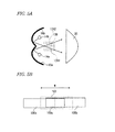
- FIG. 5 includes explanatory views each explaining the light distribution pattern formed by the bulbs 14a and 14b of the optical unit of the present embodiment.
- the optical unit 10 of the present embodiment has the two bulbs 14.
- the bulb 14a emits light in the forward direction of the vehicle via the projection lens 20, and is capable of forming a slender first illuminated area 100a extending in the vehicle width direction W, as shown in FIG. 5B .
- the other bulb 14b similarly emits light in the forward direction of the vehicle via the projection lens 20, and is capable of forming a slender second illuminated area 100b extending in the vehicle width direction W.
- the shape of the light source of the bulb 14a itself is formed into a shape in correspondence to the slender light distribution pattern of FIG.
- Each of the reflectors 16a and 16b is a reflector formed with reference to, e.g., a paraboloid of revolution or the like.
- the second illuminated area 100b is coupled to the first illuminated area 100a in overlapping relation in a lateral direction of the first illuminated area 100a relative to an optical axis O.
- FIG. 5B shows an example in which an end portion area of the first illuminated area 100a and an end portion area of the second illuminated area 100b overlap each other to form an overlapped portion 100c.
- the adjustment of the overlapped portion 100c can be performer by, e.g., position adjustment of the individual bulbs 14a and 14b and shape adjustment of the reflectors 16a and 16b.
- the lights are superimposed in the vicinity of the central portion so that the luminous intensity can be enhanced, and a dark portion is not formed in the coupled portion of the first and second illuminated areas 100a and 100b so that improvements in visibility and quality at the time of use of the high beam can be facilitated.
- the end portion areas of the first and second illuminated areas 100a and 100b are not necessarily required to be overlapped, and the end portion area of the first illuminated area 100a may be precisely coupled to the end portion area of the second illuminated area 100b without the overlapped portion.
- FIG. 5B shows the first and second illuminated areas 100a and 100b which are displaced from each other in the vertical direction in order to explain that the end portion areas of the first and second illuminated areas 100a and 100b are overlapped, they are actually disposed without the vertical displacement.
- FIG. 5B shows a light-blocked area 102 blocked by the first shades 12A1 and 12A2 and the second shade 12b in a broken line.
- the sizes of the first shades 12A1 and 12A2 are determined such that the light-blocked area 102 is larger than the overlapped portion 100c so as to completely cover the overlapped portion 100c.
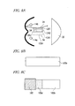
- FIG. 6 shows examples of a control state of the optical unit 10 and an image of the light distribution pattern to be formed.
- the light distribution patterns shown in FIG. 6 show states thereof each in which the light distribution pattern formed by the high-beam optical unit 10 is added to an upper portion of a low-beam light distribution pattern Lo formed by a low-beam optical unit.
- FIG. 6 shows examples in which the first shades 12A1 and 12A2 of the optical unit 10 for forming the light distribution patterns shown in FIG. 6 are different from those of the optical unit 10 shown in each of FIGS. 2 to 4 in the width in the vehicle width direction W and the disposition position. That is, FIG.
- the light distribution pattern can be changed also by changing the width and the disposition position of each of the first shades 12A1 and 12A2.
- the vehicle headlamp apparatus 210 of the present embodiment performs the turning on/off control of the bulbs 14a and 14b, and also performs control of advancement and retreat of the first shades 12A1 and 12A2 in accordance with the position or presence of a forward vehicle and a pedestrian in a forward area acquired by a forward visual recognition apparatus mounted on a vehicle side such as, e.g., a camera or the like to select the optimum light distribution pattern.
- a forward visual recognition apparatus mounted on a vehicle side such as, e.g., a camera or the like to select the optimum light distribution pattern.
- FIG 6 a description will be given by using, as an example, the case where only movement control of the first shades 12A1 and 12A2 is performed with the bulbs 14a and 14b remaining in the turned-on state.
- the control section 228 turns on the bulbs 14a and 14b, and brings the movement mechanism 18 into a non-controlled state in accordance with whether vehicles or the like are present in a forward area of a vehicle on which the vehicle headlamp apparatus is mounted to move the first shades 12A1 and 12A2 to the retreated position. That is, by bringing the vehicle headlamp apparatus into a completely non-light-blocking state, the first and second illuminated areas 100a and 100b including the overlapped portion 100c in FIG. 5B come to be illuminated. This state corresponds to a complete high-beam illumination state. Consequently, the visibility in a forward area of a driver of the vehicle can be improved. In addition, by the formation of the overlapped portion 100c, the luminous intensity in the vicinity of the center is enhanced, and the visibility is further improved.
- a control 2 creates a maximum light-blocking state in the turned-on state of the bulbs 14a and 14b.
- the control section 228 turns on the bulbs 14a and 14b, and controls the solenoids 26a and 26b of the control mechanism 18 in accordance with whether vehicles or the like are present in the forward area of a vehicle on which the vehicle headlamp apparatus is mounted to move the first shades 12A1 and 12A2 to the advanced position.
- By blocking light using the first shades 12A1 and 12A2 there is formed a special high-beam light distribution pattern Hi 2 in which high-beam light is not emitted to an area from the vicinity of the center ahead of the vehicle (long distance) to the vicinity of the center in the opposite lane (short distance).
- This light distribution pattern is a light distribution pattern which is preferably used, e.g., when a large number of oncoming vehicles are present in a long-distance area and in a short-distance area in the opposite lane, no leading vehicle is present in a short-distance area on the velaicle ⁇ s lane side, and no pedestrian is present on a road shoulder of the opposite lane. In this case, it is possible to prevent the glare to a forward vehicle present in the long-distance area and the oncoming vehicle present in the short-distance area on the opposite lane side, and improve the view range of a driver of the vehicle on the vehicle's lane side and the visibility in the road shoulder on the opposite lane side.
- a control 3 is a light distribution pattern which allows the prevention of the glare to the short-distance area in the opposite lane in the turned-on state of the bulbs 14a and 14b.
- the control section 228 turns on the bulbs 14a and 14b, and controls the solenoid 26b of the movement mechanism 18 in accordance with whether vehicles or the like are present in the forward area of a vehicle on which the vehicle headlamp apparatus is mounted to move only the first shade 12A2 to the advanced position.
- By blocking light using the first shade 12A2 there can be formed a special high-beam light distribution pattern Hi 3 in which the high-beam light is not emitted to the vicinity of the center in the opposite lane.
- This light distribution pattern is a light distribution pattern which is preferably used, e.g., when an oncoming vehicle is present in the short-distance area in the opposite lane, no leading vehicle is present in the long-distance area, and no pedestrian is present on the road shoulder of the opposite lane. In this case, it is possible to prevent the glare to the oncoming vehicle on the opposite lane side, especially in the short-distance area, and improve the view range of the driver of the vehicle on the vehicle's lane side and in the long-distance area, and the visibility in the road shoulder on the opposite lane side.
- a control 4 is a light distribution pattern which is preferably used when a forward vehicle is present in the vicinity of the center ahead of a vehicle on which the vehicle headlamp apparatus is mounted, no leading vehicle is present in the short-distance area on the vehicle's lane side, and no pedestrian is present on the opposite lane side in the turned-on state of the bulbs 14a. and 14b.
- the control section 228 turns on the bulbs 14a and 14b, and controls the solenoid 26a of the movement mechanism 18 in accordance with whether vehicles or the like are present in the forward area of the vehicle to move only the first shade 12A1 to the advanced position.
- This light distribution pattern is a light distribution pattern which is preferably used, e.g., when a forward vehicle is present in the vicinity of the center ahead of the vehicle (long distance), no oncoming vehicle is present in the short-distance area in the opposite lane, no leading vehicle is present in the short-distance area on the vehicle's lane side, and no pedestrian is present on the opposite lane side.
- the advancement and retreat of the first shades 12A1 and 12A2 it becomes possible to form the light distribution patterns which can not be realized only by the turning on/off control of the bulbs 14a and 14b. Further, besides the control of the first shades 12A1 and 12A2 in the controls 1 to 4, by adding the turning on/off control of the bulbs 14a and 14b, it is possible to form even more light distribution patterns. For example, in the control 2 explained using FIG. 6 , by turning on only the bulb 14a and turning off the bulb 14b, there can be formed what is called a "left-side high light distribution pattern" in which mainly the vehicle's lane side is brought into a high-beam state. Conversely, by turning on only the bulb 14b and turning off the bulb 14a, there can be formed a light distribution pattern substantially equal to the low-beam light distribution pattern in which mainly the view range in the road shoulder of the opposite lane is illuminated using the high beam.
- the "left-side high light distribution pattern" can be formed.
- a "right-side high light distribution pattern” which brings mainly the opposite lane side into the high-beam state.
- FIG 8 shows a modified example of the first shade 12A and the second shade 12B.
- the description has been given of the example in which the member having the substantially L-shaped cross section when viewed from above as shown in FIG 3 is employed.
- FIG. 7A shows the flat plate-like first shades 12A1 and 12A2 extending in the vehicle width direction W which are disposed adjacent to each other in the vehicle width direction W via a specific gap, and are movable between the advanced position which blocks a part of light emitted from the bulb and the retreated position which does not block the light.
- the second shade 12B is engaged with the end portions in the vehicle width direction W of the first shades 12A, driven by the first shades 12A to move between the advanced position and the retreated position, and covers the gap between the adjacent first shades 12A. Similar to the structure shown in FIG. 4 , the first shades 12A1 and 12A2 move between the advanced position and the retreated position using the solenoids 26a and 26b of the movement mechanism 18 independently of each other. Consequently, when the first shade 12A moves to the advanced position, the second shades 12B1 and 12B2 engaged with the first shade 12A1 are driven thereby. In addition, when the first shade 12A2 moves to the advanced position, the second shades 12B2 and 12B1 engaged with the first shade 12A2 are driven thereby.
- the second shades 12B1, 12B2, and 12B1 are driven thereby. That is, by moving the first shades 12A1 and 12A2, the same state as the state explained using FIG. 3 can be created.
- the number of second shades 12B to be formed is larger than the number of first shades 12A to be formed by one, and both end portions in the vehicle width direction of the first shade 12A are engageable.
- the second shades 12B each having the function of preventing light leakage can be reliably driven.
- first and second shades 12A and 12B can be structured as a simple plate-like member, the simplification of the optical unit 10 can be facilitated.
- the advantage is achieved that the number of parts can be reduced.
- the illuminated area of the high-beam light distribution pattern to be formed can be easily subdivided.
- the number of subdivided areas can be easily increased or decreased.
- FIG. 7C shows a modified example of the L-shaped first shades 12A1 and 12A2 shown in FIG. 3 , and the second shade 12B is also formed into the L shape.
- the light-blocked area can be formed also by the second shade 12B. That is, it becomes possible to change the light-blocked area, and further increase the number of types of the light distribution patterns.
- FIGS. 8A to 8C are explanatory views each explaining a state of reflection and a state of superimposition of reflected lights in the case where an extended portion 34 of the second shade 12B extending in the direction of the optical axis O has a reflective surface.
- the extended portion 34 of the second shade 12B2 disposed between the adjacent first shades 12A is formed with reflective surfaces on both surfaces thereof such that light from the light source is reflected and guided forward.
- the second shade 12B2 is disposed at the end portion on the non-adjacent side of the first shade 12A1 or the first shade 12A2 as the second shade 12B1
- the extended portion 34 of the second shade 12B2 is formed with the reflective surface only on one of the surfaces which serves as the outside surface.
- the reflective surface can be formed by, e.g., joining or coating of a reflective member. Since light from the bulbs 14 does not reach the inside surface of the second shade 12B1, the reflective surface is not necessary, and therefore the reflective surface is not formed on this surface, whereby the reduction in the cost of the parts can be facilitated.
- the surface state of the reflective surface is formed such that the light incident on the reflective surface on the side of the bulb 14a is guided to a specific position in the first illuminated area 100a of FIG. 3 .
- the surface state of the reflective surface is formed such that the light incident on the reflective surface on the side of the bulb 14b is guided to a specific position in the second illuminated area 100b,
- FIG. 8B shows the second illuminated area 100b formed when only the bulb 14b is turned on and the first shades 12A1 and 12A2 are moved to the retreated position (non-light-blocking state).
- FIG. 8C shows the second illuminated area 100b and the light-blocked area 102 formed when only the bulb 14b is turned on and the first shade 12A2 is moved to the light-blocking position.
- the reflected light reflected by the second shade 12B1 is superimposed on a position on the side of the light-blocked area 102 of the second illuminated area 100b, and a superimposed portion 100d is thereby formed.
- the angle or the position of the reflective surface may be adjustable. In this case, it becomes possible to change the position of the superimposed portion by the reflected light, and enhance the luminous intensity of the area in correspondence to the preference of the driver, and enhance a utility value of the reflected light.
- the second shades 12B, which are driven by the first shades 12A can be provided so as to cover the gap between the first shades 12A, which are disposed adjacent to each other, even when the shapes thereof are appropriately changed, it is possible to provide the optical unit, which smoothly operates without the abrasion of the individual first shades 12A resulting from the direct contact thereof, while also preventing the light leakage from between the adjacent first shades 12A.
- the drive system can be appropriately selected, and the similar effect can be obtained by using, e.g., a motor or a cam mechanism.
Landscapes
- Engineering & Computer Science (AREA)
- General Engineering & Computer Science (AREA)
- Mechanical Engineering (AREA)
- Physics & Mathematics (AREA)
- Microelectronics & Electronic Packaging (AREA)
- Optics & Photonics (AREA)
- Non-Portable Lighting Devices Or Systems Thereof (AREA)
Applications Claiming Priority (1)
| Application Number | Priority Date | Filing Date | Title |
|---|---|---|---|
| JP2010131712A JP2011258406A (ja) | 2010-06-09 | 2010-06-09 | 光学ユニット |
Publications (2)
| Publication Number | Publication Date |
|---|---|
| EP2395280A2 true EP2395280A2 (de) | 2011-12-14 |
| EP2395280A3 EP2395280A3 (de) | 2014-01-08 |
Family
ID=44487183
Family Applications (1)
| Application Number | Title | Priority Date | Filing Date |
|---|---|---|---|
| EP11168042.7A Withdrawn EP2395280A3 (de) | 2010-06-09 | 2011-05-30 | Optische Einheit für Fahrzeugsbeleuchtungseinrichtung |
Country Status (3)
| Country | Link |
|---|---|
| US (1) | US8511873B2 (de) |
| EP (1) | EP2395280A3 (de) |
| JP (1) | JP2011258406A (de) |
Cited By (2)
| Publication number | Priority date | Publication date | Assignee | Title |
|---|---|---|---|---|
| FR3022326A1 (fr) * | 2014-06-16 | 2015-12-18 | Valeo Vision | Module d'eclairage et/ou de signalisation rotatif |
| EP4360952A4 (de) * | 2021-06-21 | 2024-07-31 | Koito Mfg Co Ltd | Lichtverteilungssteuerungsvorrichtung, fahrzeuglichtsystem und lichtverteilungssteuerungsverfahren |
Families Citing this family (10)
| Publication number | Priority date | Publication date | Assignee | Title |
|---|---|---|---|---|
| US8840291B2 (en) * | 2011-10-26 | 2014-09-23 | Federal-Mogul Ignition Company | LED lamp assembly with heat sink |
| US9033562B2 (en) * | 2011-12-27 | 2015-05-19 | Ichikoh Industries, Ltd. | Vehicle headlamp |
| JP5828278B2 (ja) * | 2011-12-27 | 2015-12-02 | 市光工業株式会社 | 車両用前照灯 |
| JP6051533B2 (ja) * | 2012-02-02 | 2016-12-27 | 市光工業株式会社 | 車両用前照灯および車両用前照灯装置 |
| JP2014132546A (ja) * | 2012-12-04 | 2014-07-17 | Koito Mfg Co Ltd | 車両用照明装置 |
| TWI565604B (zh) * | 2012-12-25 | 2017-01-11 | 鴻海精密工業股份有限公司 | 車燈系統 |
| CN103900004A (zh) * | 2012-12-26 | 2014-07-02 | 鸿富锦精密工业(深圳)有限公司 | 车灯系统 |
| US9534759B2 (en) * | 2014-03-14 | 2017-01-03 | Ford Global Technologies, Llc | Lamp adjuster to control margins |
| JP6517556B2 (ja) * | 2015-03-24 | 2019-05-22 | スタンレー電気株式会社 | 車両用灯具 |
| US10207628B1 (en) * | 2018-02-20 | 2019-02-19 | Ford Global Technologies, Llc | Vehicle light assemblies |
Citations (1)
| Publication number | Priority date | Publication date | Assignee | Title |
|---|---|---|---|---|
| JP2007179969A (ja) | 2005-12-28 | 2007-07-12 | Koito Mfg Co Ltd | 車両用灯具 |
Family Cites Families (12)
| Publication number | Priority date | Publication date | Assignee | Title |
|---|---|---|---|---|
| FR1306770A (fr) * | 1961-09-27 | 1962-10-19 | Telefunken Patent | Installation d'éclairage de route pour véhicules automobiles équipée de phares à occultation partielle |
| JP3943260B2 (ja) * | 1998-09-17 | 2007-07-11 | 株式会社小糸製作所 | 車両用前照灯 |
| FR2841512B1 (fr) * | 2002-06-28 | 2005-01-07 | Valeo Vision | Dispositif projecteur pour vehicule automobile eclairant des points de portique |
| FR2883066B1 (fr) * | 2005-03-08 | 2007-05-11 | Valeo Vision Sa | Projecteur lumineux a plusieurs fonctions pour vehicule automobile |
| JP4400884B2 (ja) * | 2005-06-08 | 2010-01-20 | 株式会社小糸製作所 | 車輌用灯具 |
| JP4717696B2 (ja) * | 2006-04-20 | 2011-07-06 | 株式会社小糸製作所 | 車両用前照灯の灯具ユニット |
| DE102006031819A1 (de) * | 2006-07-07 | 2008-01-10 | Hella Kgaa Hueck & Co. | Projektionsscheinwerfer für Fahrzeuge |
| JP5106177B2 (ja) * | 2008-02-27 | 2012-12-26 | 株式会社小糸製作所 | 車輌用前照灯 |
| WO2009130655A2 (en) * | 2008-04-25 | 2009-10-29 | Philips Intellectual Property & Standards Gmbh | Lamp assembly |
| JP5442222B2 (ja) * | 2008-07-03 | 2014-03-12 | 株式会社小糸製作所 | 車両用前照灯 |
| JP2011100662A (ja) * | 2009-11-06 | 2011-05-19 | Koito Mfg Co Ltd | 車両用前照灯装置 |
| FR2953468B1 (fr) * | 2009-12-08 | 2012-05-25 | Valeo Vision | Module optique apte a generer un faisceau lumineux de type code et un faisceau lumineux selectif |
-
2010
- 2010-06-09 JP JP2010131712A patent/JP2011258406A/ja active Pending
-
2011
- 2011-05-24 US US13/114,194 patent/US8511873B2/en not_active Expired - Fee Related
- 2011-05-30 EP EP11168042.7A patent/EP2395280A3/de not_active Withdrawn
Patent Citations (1)
| Publication number | Priority date | Publication date | Assignee | Title |
|---|---|---|---|---|
| JP2007179969A (ja) | 2005-12-28 | 2007-07-12 | Koito Mfg Co Ltd | 車両用灯具 |
Cited By (3)
| Publication number | Priority date | Publication date | Assignee | Title |
|---|---|---|---|---|
| FR3022326A1 (fr) * | 2014-06-16 | 2015-12-18 | Valeo Vision | Module d'eclairage et/ou de signalisation rotatif |
| EP2957464A1 (de) * | 2014-06-16 | 2015-12-23 | Valeo Vision | Drehbares beleuchtungs- und/oder signalisierungsmodul |
| EP4360952A4 (de) * | 2021-06-21 | 2024-07-31 | Koito Mfg Co Ltd | Lichtverteilungssteuerungsvorrichtung, fahrzeuglichtsystem und lichtverteilungssteuerungsverfahren |
Also Published As
| Publication number | Publication date |
|---|---|
| EP2395280A3 (de) | 2014-01-08 |
| US20110305033A1 (en) | 2011-12-15 |
| JP2011258406A (ja) | 2011-12-22 |
| US8511873B2 (en) | 2013-08-20 |
Similar Documents
| Publication | Publication Date | Title |
|---|---|---|
| US8511873B2 (en) | Optical unit | |
| KR101239454B1 (ko) | 차량용 전조등 장치 | |
| CN100562685C (zh) | 车辆用前照灯 | |
| US10634303B2 (en) | Optical unit | |
| KR101315659B1 (ko) | 차량용 등기구 | |
| US6634778B2 (en) | Vehicular headlamp for controlling light distribution of vehicular headlamp having improved synthesized light distribution pattern | |
| US8182126B2 (en) | Automotive headlamp apparatus synthesizing light distribution patterns of right and left lamp units | |
| JP5398443B2 (ja) | 車両用前照灯装置 | |
| US7118258B2 (en) | Vehicular headlamp | |
| US20110002136A1 (en) | Optical device for a motor vehicle | |
| JP5107821B2 (ja) | 車両用前照灯装置 | |
| EP2695772A2 (de) | Fahrzeugscheinwerfer | |
| JP2010000957A (ja) | 車両用前照灯装置 | |
| JP7155124B2 (ja) | 灯具ユニットおよび車両用前照灯 | |
| EP2100771B1 (de) | Fahrzeugscheinwerfervorrichtung und Verfahren zu deren Steuerung | |
| JP2002304905A (ja) | 車両用灯具 | |
| JP5539796B2 (ja) | 車両用前照灯システム | |
| JP2010235108A (ja) | 車両用前照灯装置 | |
| KR20120011213A (ko) | 차량용 헤드 램프 | |
| JP6142541B2 (ja) | 車両用前照灯 | |
| JP5634406B2 (ja) | 車両用前照灯装置 | |
| JP4341538B2 (ja) | ヘッドランプ | |
| JP5636485B2 (ja) | 灯具ユニット | |
| KR20180107370A (ko) | 멀티 시그널부를 갖는 차량 전조등용 쉴드 구조체 및 이를 구비한 차량용 전조등 | |
| JP2010092754A (ja) | 車両用前照灯装置 |
Legal Events
| Date | Code | Title | Description |
|---|---|---|---|
| 17P | Request for examination filed |
Effective date: 20110530 |
|
| AK | Designated contracting states |
Kind code of ref document: A2 Designated state(s): AL AT BE BG CH CY CZ DE DK EE ES FI FR GB GR HR HU IE IS IT LI LT LU LV MC MK MT NL NO PL PT RO RS SE SI SK SM TR |
|
| AX | Request for extension of the european patent |
Extension state: BA ME |
|
| PUAI | Public reference made under article 153(3) epc to a published international application that has entered the european phase |
Free format text: ORIGINAL CODE: 0009012 |
|
| PUAL | Search report despatched |
Free format text: ORIGINAL CODE: 0009013 |
|
| AK | Designated contracting states |
Kind code of ref document: A3 Designated state(s): AL AT BE BG CH CY CZ DE DK EE ES FI FR GB GR HR HU IE IS IT LI LT LU LV MC MK MT NL NO PL PT RO RS SE SI SK SM TR |
|
| AX | Request for extension of the european patent |
Extension state: BA ME |
|
| RIC1 | Information provided on ipc code assigned before grant |
Ipc: F21V 14/08 20060101AFI20131202BHEP Ipc: F21S 8/12 20060101ALI20131202BHEP |
|
| STAA | Information on the status of an ep patent application or granted ep patent |
Free format text: STATUS: THE APPLICATION HAS BEEN WITHDRAWN |
|
| 18W | Application withdrawn |
Effective date: 20160401 |