EP2394884A1 - Appareil de direction assistée électrique - Google Patents
Appareil de direction assistée électrique Download PDFInfo
- Publication number
- EP2394884A1 EP2394884A1 EP11169431A EP11169431A EP2394884A1 EP 2394884 A1 EP2394884 A1 EP 2394884A1 EP 11169431 A EP11169431 A EP 11169431A EP 11169431 A EP11169431 A EP 11169431A EP 2394884 A1 EP2394884 A1 EP 2394884A1
- Authority
- EP
- European Patent Office
- Prior art keywords
- steering
- shaft
- elastic member
- rack
- steering wheel
- Prior art date
- Legal status (The legal status is an assumption and is not a legal conclusion. Google has not performed a legal analysis and makes no representation as to the accuracy of the status listed.)
- Granted
Links
Images







Classifications
-
- B—PERFORMING OPERATIONS; TRANSPORTING
- B62—LAND VEHICLES FOR TRAVELLING OTHERWISE THAN ON RAILS
- B62D—MOTOR VEHICLES; TRAILERS
- B62D1/00—Steering controls, i.e. means for initiating a change of direction of the vehicle
- B62D1/02—Steering controls, i.e. means for initiating a change of direction of the vehicle vehicle-mounted
- B62D1/16—Steering columns
-
- B—PERFORMING OPERATIONS; TRANSPORTING
- B62—LAND VEHICLES FOR TRAVELLING OTHERWISE THAN ON RAILS
- B62D—MOTOR VEHICLES; TRAILERS
- B62D3/00—Steering gears
- B62D3/02—Steering gears mechanical
- B62D3/12—Steering gears mechanical of rack-and-pinion type
-
- B—PERFORMING OPERATIONS; TRANSPORTING
- B62—LAND VEHICLES FOR TRAVELLING OTHERWISE THAN ON RAILS
- B62D—MOTOR VEHICLES; TRAILERS
- B62D7/00—Steering linkage; Stub axles or their mountings
- B62D7/22—Arrangements for reducing or eliminating reaction, e.g. vibration, from parts, e.g. wheels, of the steering system
- B62D7/224—Arrangements for reducing or eliminating reaction, e.g. vibration, from parts, e.g. wheels, of the steering system acting between the steering wheel and the steering gear, e.g. on the steering column
-
- B—PERFORMING OPERATIONS; TRANSPORTING
- B62—LAND VEHICLES FOR TRAVELLING OTHERWISE THAN ON RAILS
- B62D—MOTOR VEHICLES; TRAILERS
- B62D7/00—Steering linkage; Stub axles or their mountings
- B62D7/22—Arrangements for reducing or eliminating reaction, e.g. vibration, from parts, e.g. wheels, of the steering system
- B62D7/226—Arrangements for reducing or eliminating reaction, e.g. vibration, from parts, e.g. wheels, of the steering system acting on the steering gear
-
- B—PERFORMING OPERATIONS; TRANSPORTING
- B62—LAND VEHICLES FOR TRAVELLING OTHERWISE THAN ON RAILS
- B62D—MOTOR VEHICLES; TRAILERS
- B62D7/00—Steering linkage; Stub axles or their mountings
- B62D7/22—Arrangements for reducing or eliminating reaction, e.g. vibration, from parts, e.g. wheels, of the steering system
- B62D7/228—Arrangements for reducing or eliminating reaction, e.g. vibration, from parts, e.g. wheels, of the steering system acting between the steering gear and the road wheels, e.g. on tie-rod
Definitions
- the present invention relates to an electric power steering apparatus.
- Electric power steering apparatuses in which a steering wheel is coupled to tires through a steering shaft are provided to reduce a steering force to be generated by a driver with an auxiliary torque, generated by an electric motor according to a magnitude of an applied steering torque.
- the auxiliary torque is transmitted to the steering shaft in addition to the steering force by the driver.
- JP 2006-264621 A discloses an electric power steering apparatus including a rack shaft movable in a width direction of the vehicle, a rack housing for housing the rack shaft, first and second bearings installed between the rack shaft and the rack housing, and an elastic member, installed between the rack shaft and the rack housing, abutting the rack shaft and the rack housing.
- the elastic member suppresses vibrations in a radial direction of the rack shaft.
- JP2003-19967 A discloses a steering apparatus for a vehicle having a steering wheel returning mechanism including a left lever and a right lever rotating with linkage with steering the steering wheel, a spring intervened between ends of the left and right levers, and a center stopper pin on which the other end of the left or the right lever abut.
- the spring elongates until the other end of either of the left or the right lever abuts the center stop pin.
- the steering wheel returns in the opposite direction by an amount of elongation of the spring. Accordingly, a detection value of a steering wheel angle detection unit can be equalized to a turning angle detection of steering wheels. This stops an unnecessary current flowing in the electric power steering unit to save energy.
- An aspect of the present invention provides an electric power steering apparatus, including a motor generating, in accordance with a steering torque applied to a steering wheel, an assist torque transmitted to a steering shaft, for connecting the steering wheel to a tire, comprising:
- the steering shaft comprises a steering wheel shaft
- the housing comprises a column housing configured to house the steering wheel shaft.
- the elastic member is disposed between the steering wheel shaft and the column housing.
- the steering shaft comprises a rack and pinion mechanism including a rack shaft and a pinion shaft
- the housing comprises a rack housing configured to house the rack shaft.
- the elastic member may be disposed between the rack shaft and the rack housing.
- the elastic member may be installed between the steering shaft and the column housing.
- the elastic member When the steering shaft rotates in response to turning the steering wheel, the elastic member is deformed in accordance with rotation displacement or displacement in the width direction of the steering shaft.
- the elastic member When a rotation direction of the steering wheel is changed, the elastic member may restore to the original state (shape) with restoring force.
- the restoring force may be applied to the steering shaft, which returns the steering shaft in the opposite rotation direction such that the elastic member in the deformed state returns to the neutral state, so that a response to change in rotation direction of the steering wheel can be increased with a simple configuration.
- two bearings may be installed in the housing in such a state that the bearing contact the steering shaft, and the elastic member may be installed between the bearings, so that the steering shaft is firmly supported by the bearings. Accordingly, if an external force were applied to the steering shaft, the external force may be absorbed by the bearings, so that influence to the friction at the elastic member can be excluded. As a result, the returning force that returns the steering shaft may be stable, and a preferable steering feeling may provided with a simple configuration because the friction force at the elastic member may not vary between when the external force is applied to the steering shaft and when not applied.
- the annular channel may be formed in the steering shaft and have such a dimension that the elastic member is fitted thereinto, so that the elastic member can be easily attached to the steering shaft. This configuration can allow the elastic member to be easily attached to the steering shaft.
- the elastic member has a rectangular shape on the longitudinal cross section.
- the elastic member is formed to have a circle or similar shape on a longitudinal cross section, a contact area of the elastic member with the steering shaft or the housing may vary between when the external force is applied to the elastic member in a radial direction and when not applied.
- the elastic member may be formed to have a rectangular shape on a longitudinal cross section, so that the contact area does not vary between when the external force is applied to the elastic member in a radial direction and when not applied, which may result in stableness in returning force applied to the steering shaft.
- the elastic member comprises a rubber member.
- This configuration can provide an elastic deformation to such an extent that the returning force capable of returning the steering shaft in the opposite direction is surely generated.
- the rubber member has an attenuation coefficient, the rubber member can attenuate vibrations from the road and variations generated at engagement in the reduction mechanism and the rack and pinion mechanism.
- a torque sensor is provided in the steering shaft, and the elastic member is installed on a side of the tires from the torque sensor.
- This configuration may result in an accurate detection of the steering wheel torque Ts because the elastic member is not disposed between the steering wheel and the torque sensor, and a remaining torque due to a friction at the elastic member is not detected, so that the steering torque can be detected accurately.
- vibrations generated at engagement in the reduction mechanism and the rack and pinion mechanism can be absorbed by the elastic member, so that these variations cannot be easily detected, which may provide a higher accuracy in the torque sensor and a preferable steering feeling.
- the electric power steering apparatus further includes a supporting member, disposed between the steering shaft and the elastic member, configured to be displaced by a rotation of a predetermined angle or a predetermined distance in accordance with the rotation displacement or a displacement, in the width direction of the vehicle, of the steering shaft with slidable support for the steering shaft.
- the elastic member is fixed to the supporting member and abuts the housing. Accordingly, because the supporting member having the elastic member is displaced by a rotation of a predetermined angle or predetermined distance in accordance with the rotation displacement or a displacement, in the width direction of the vehicle, of the steering shaft with slidable support for the steering shaft, the elastic member can be elastically deformed and restored to the original shape when rotation direction of the steering wheel is changed.
- the elastic member abuts the housing as well as the supporting member provides slidable support for the steering shaft. Accordingly, the friction force between the elastic member and the housing, restricts rotation or a displacement of the supporting member in the vehicle width direction at a position after rotation of a predetermine angle and displacement of a predetermined distance in the vehicle width direction. Accordingly, the steering shaft can be rotated or displaced in the vehicle width direction while the steering shaft moves with slidable support by the supporting member. Accordingly, because the steering shaft can stably rotate and is displaced in a vehicle width direction with slidable support, the steering wheel can be stably returned. Accordingly, the vehicle can be stably controlled with a quick response steering.
- the supporting member is made of a plastic material.
- the supporting member has a relative low friction coefficient, so that the steering shaft can be supported with smoothly sliding, which results in smooth rotation or displacement of the steering shaft in the vehicle width direction.
- the housing comprises a connection part where the first rack housing is connected to the second rack housing.
- the elastic member and the supporting member are installed near the connection part between the first rack housing and the second rack housing. Accordingly, this makes it easier to install the elastic member and the supporting member in the first rack housing in manufacturing, so that work efficiency for installing the elastic member and supporting member increases.
- a predetermined gap is provided between the rack shaft and the first and second bearings, so that the first and second bearings do not support the rack shaft. Accordingly, when an external force is applied to the rack shaft from an outside of the first and second bearings, influence of the external force directly reach the elastic member. Therefore, the elastic member elastically deforms in a radial direction, so that a friction force of the elastic member generated when the rack shaft moves in the vehicle width direction varies. In other words, a problem is that a force returning the rack shaft in the opposite direction is unstable, so that a feeling in steering the steering wheel becomes worse because the friction force of the elastic member varies between when the external force is applied to the rack shaft and when not applied.
- a problem is that a load in steering the steering wheel varies between steering from when the left lever or the right lever hits the center stopper pin and steering after the left lever or the right lever hits the center stopper pin, so that steering feeling varies from light feeling to heavy feeling as well as the steering feeling becomes worse because the left lever or the right lever hits the center stopper pin.
- the steering wheel return mechanism disclosed in JP2003-19967 A has a problem of increase in the number of parts and a manufacturing cost due to a complicated mechanism because the steering wheel return mechanism is formed with the left lever, the right lever, a spring, the center stop pin, and the like.
- the present invention is developed in consideration of these circumstances and provides an electric power steering apparatus capable of providing a preferable steering feeling in addition to an improved response in switching of the turning direction of the steering wheel with a simple configuration.
- the electric power steering apparatus provides a preferable steering feeling with a higher responsibility in switching the direction of turning the steering wheel with a simple configuration.
- a detection accuracy of a torque sensor 1 can be increased, so that a preferable steering feeling is provided.
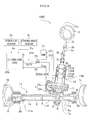
- Fig. 1 is a block diagram of an electric power steering apparatus according to a first embodiment of the present invention.
- an electric power steering apparatus 100A is an assist device for assisting steering with a steering wheel 3 to turn tires (front wheels) 1R, 1L using an electric motor 4.
- a steering wheel shaft 3a is provided with a steering wheel 3 at an upper end thereof, a shaft 3c, and a pinion shaft 7, which shafts are connected with two universal joints 3b, 3b.
- a pinion gear 7a installed at a lower end of the pinion shaft 7 is engaged with a rack gear 8a on a rack shaft 8 capable of reciprocating motion in a vehicle width direction (movable in an axial direction), and both ends of the rack shaft 8 are connected to the right and left tires 1R, 1L through tie rods 9, 9.
- the electric power steering apparatus 100A can change a traveling direction of the vehicle when the steering wheel 3 is turned.
- the rack shaft 8, the rack gear 8a, the tie rods 9, 9 form a turning mechanism.
- the pinion shaft 7 and the rack shaft 8 forms a rack and pinion mechanism.
- the steering wheel shaft 3a serving as a steering shaft is housed in a column housing 10 to be rotatably supported about the axis thereof in which an upper part, an intermediate part, and a lower part of the column housing 10 are rotatably supported by bearing 3d, 3e, and 3f respectively.
- the steering wheel shaft 3a is provided with a seal member 3g on an upper side of the bearing 3d to seal a space between the steering wheel shaft 3a and the column housing 10.
- the steering wheel shaft 3a is provided with a torque sensor 12 and an elastic member 6.
- the torque sensor 12 detects a steering wheel torque Ts generated on the steering wheel shaft 3a connected to the steering wheel 3 by a driver's operation of the steering wheel 3.
- the torque sensor 12 includes a first magnetostriction film 121A, a second magnetostriction film 121B, which are formed around an entire circumference of the steering wheel shaft 3a, a first detection coil 122A disposed around an outer face of the first magnetostriction film 121A with a predetermined gap, and a second detection coil 122B disposed around an outer face of the second magnetostriction film 121B with a predetermined gap.
- the first magnetostriction film 121A and the second magnetostriction film 121B comprise a magnetostriction member having a positive magnetostriction constant such as an Fe-Ni system or an Fe-Cr system and are disposed along the axial direction of the steering wheel shaft 3a with a gap.
- the first magnetostriction film 121A and the second magnetostriction film 121B are caused to have anisotropies in opposite direction and are formed to have a predetermined film thicknesses(for example, not greater than 30 ⁇ m) by, for example, a plating method or an evaporation method.
- a steering wheel torque Ts is generated and transmitted to the steering wheel shaft 3a.
- the transmitted steering wheel torque Ts is detected by the torque sensor 12 and outputted as detection signals, wherein the first detection coil 122A outputs a signal voltage VT1 and the second detection coil 122B outputs a signal voltage VT2.
- the signal voltages VT1 and VT2 outputted by the first detection coil 122A and the second detection coil 122B are amplified by a differential amplifier 21 and inputted into a steering control ECU 200 as a torque signal VT3.
- Fig. 2 is an enlarged longitudinal cross section of a part of the electric power steering apparatus around an elastic member 6, taken along (in parallel to) the axis AX1 (shown in Fig. 3C ) of the steering wheel shaft 3a.
- the elastic member 6 capable of being elastically deformed is fitted into an annular channel 3k formed in an outer circumferential surface of the steering wheel 3a to be mounted on the steering wheel shaft 3a.
- the elastic member 6 having a rectangular shape on the longitudinal cross section is a member for applying to the steering wheel shaft 3a a force returning the steering wheel shaft 3a in an opposite direction (to a neutral position) when a turning direction of the steering wheel is switched.
- the elastic member 6 comprises, for example, a rubber member, or a spring member and is provided between the steering wheel shaft 3a and the column housing 10 in such a state that an outer circumference of the elastic member 6 contacts an inner surface of the column housing 10.
- the elastic member 6 is installed between the steering wheel shaft 3a and the column housing 10 with a suitable pressure (compression state).
- a suitable pressure compression state
- a dimension of the elastic member 6 in radial direction of the steering wheel shaft 3a is made slightly greater than a distance between the steering wheel shaft 3a and the column housing 10 to provide the pressure.
- the elastic member 6 is mainly deformed by the pressure with an elastic deforming quantity in accordance with the pressure. More specifically, the greater the pressure becomes, the greater the elastic deformation quantity becomes, and the smaller the pressure becomes, the smaller the elastic deformation quantity becomes.
- the pressure can be controlled by adjusting a shape of the elastic member 6, or the distance between the steering wheel shaft 3a and the column housing 10.
- the elastic member 6 is installed on a side of the tires 1R, 1L from the torque sensor 12 and between the bearings 3d and 3e.
- the bearings 3d, 3e are disposed in the column housing 10 with a gap in a direction of the axis AX1 of the steering wheel 3a and contact an outer circumferential surface of the steering wheel shaft 3a.
- the bearings 3d, 3e rotatably support the steering wheel shaft 3a, i.e., the steering shaft.
- the pinion shaft 7 is housed in a steering gear box 11 to be rotatably supported about an axis thereof in which an intermediate part and a lower part of the pinion shaft 7 are rotatably supported by bearing 3h, 3i respectively.
- the pinion shaft 7 is provided with fastening parts 3j, 3j for connecting the universal joint 3b thereto.
- the pinion shaft 7 is provided with a seal member 3g to seal a space between the pinion shaft 7 and the steering gear box 11.
- the steering gear box 11 include a rack hosing 11A for housing and holding the rack shaft 8 and a lid part 11B for housing and holding the pinion shaft 7.
- the rack shaft 8 is provided at both ends thereof with rack ends 8b, 8b and the rack housing 11A is provided at both end thereof with housing ends 11a, 11a.
- the rack housing 11A installed are the pinion gear 7a, the rack shaft 8, a shaft bearing 3i, and a sliding bearing 14 which contacts and slidably holds the rack shaft 8.
- the electric motor 4 is a device for supplying an auxiliary steering force for reducing a steering force applied to the steering wheel 3.
- a worm gear 5a provided on the output shaft of the electric motor 4 is geared with a worm wheel gear 5b mounted on the steering wheel shaft 3a.
- the worm gear 5a and the worm wheel gear 5b form a reduction mechanism (an auxiliary torque transmission mechanism) 5.
- a rotor (not shown) of the electric motor 4, the worm gear 5a connected to the electric motor 4, the worm wheel gear 5b, the pinion shaft 7, the rack shaft 8, the rack gear 8a, and the tie rods 9, 9, etc. form a steering system.
- ⁇ M represents an angular velocity of the electric motor 4 and the term T M represents a generation torque of the electric motor 4.
- a steering wheel torque applied to the steering wheel 3 is assumed as Ts; an assist quantity assisted by a torque from the reduction mechanism 5 which boosts a torque T M generated by the electric motor 4 is assumed as A H ; and a coefficient of the assist quantity A H is assumed as k A (VS) varying as a function of, for example, a vehicle speed VS.
- Ts Th / 1 + k A VS
- the electric power steering apparatus 100A includes a motor driving circuit 23 for driving the electric motor 4, a resolver 25 for detecting a rotation angle of the electric motor 4 and generating a rotation angle signal ⁇ m , a differential amplifying circuit 21 for amplifying the outputs from the torque sensor 12 and generating a torque signal VT3, a steering angle sensor S T for detecting a steering angle of the steering wheel 3 and generating a steering angle signal ⁇ S , a vehicle speed sensor Sv for detecting a speed of a vehicle (vehicle speed VS), and a steering control ECU (Electric Control Unit) 200 for driving and controlling the electric motor 4.
- a motor driving circuit 23 for driving the electric motor 4
- a resolver 25 for detecting a rotation angle of the electric motor 4 and generating a rotation angle signal ⁇ m
- a differential amplifying circuit 21 for amplifying the outputs from the torque sensor 12 and generating a torque signal VT3, a steering angle sensor S T for detecting a steering angle of the
- the motor driving circuit 23 includes a plurality of switching elements such as a three-phase FET bridge circuit and generates voltage square waves using a DUTY signal (DUTY U, DUTY V, DUTY W) from the steering control ECU 200 to drive the electric motor 4.
- the motor driving circuit 23 has a function of detecting three phase motor currents I (IU, IV, IW) with Hall elements (not shown).
- the vehicle speed sensor Sv detects the vehicle speed VS of the vehicle as the number of pulses per unit time period.
- the steering control ECU 200 includes a computer having a CPU (Central Processing Unit), a ROM (Read Only Memory), and a RAM (Random Access Memory) and generates a DUTY signal applied to the motor driving circuit 23 to drive the electric motor 4 to have a generation torque T M by the electric motor 4 using the three phase motor currents I from the motor driving circuit 23, the rotation angle signal ⁇ mS from the resolver 25, the vehicle speed signal Vs from the vehicle speed sensor Sv, the steering angle signal ⁇ S , and the torque signal VT3 from the differential amplifying circuit 21.
- the motor driving circuit 23 drives the electric motor 4 with the generation torque T M .
- the electric power steering apparatus 100A according to a first embodiment of the present invention is configured as described above basically and will be described an operation and advantageous effects.
- the elastic member and displacement of the steering shaft when the steering angle is small will be described.
- the case where the steering angle is small is a steering state while the elastic member is being elastically deformed.
- the case where the steering angle is large is a steering status in which the elastic member is not deformed over a predetermined deformation quantity.
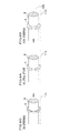
- Figs. 3A to 3C are illustrations for describing a deformation in the elastic member 6 and displacement of the steering wheel shaft 3a.
- Fig. 3A shows a neutral state
- Fig. 3B shows a counterclockwise rotation state in which the steering wheel shaft 3a rotates counterclockwise from the neutral state when a counterclockwise steering torque is applied
- Fig. 3C shows a clockwise rotation state in which the steering wheel shaft 3a rotates clockwise from the neutral state when a clockwise steering torque is applied.
- the steering wheel shaft 3a rotates counterclockwise, and the elastic member 6 disposed between the steering wheel shaft 3a and the column housing 10 is elastically deformed in accordance with rotation of the steering wheel shaft 3a. More specifically, the elastic member 6 is installed between the steering wheel shaft 3a and the column housing 10 with pressure (due to a larger dimensions than the distance between the steering wheel shaft 3a and the column housing 10) and has a friction between the column housing 10 and an outer circumferential surface thereof. Because the elastic member 6 is fitted into the annular channel 3k, the elastic member 6 as the whole does not rotate, but elastically deformed.
- the elastic member 6 restores to the original state (a shape in the neutral state as shown in Fig. 3A ).
- the restoring force is applied to the steering wheel shaft 3a, which returns the steering shaft in the opposite rotation direction such that the elastic member 6 in the deformed state returns to the neutral state, so that the steering wheel shaft 3a is returned toward the neutral state, and the steering wheel 3 is also returned toward the neutral state.
- Figs. 4A to 4E are illustrations for describing the elastic member 6 and displacement of the steering wheel shaft 3a.
- Fig. 4A shows a neutral state
- Figs. 4B and 4C show counterclockwise rotation states in which the steering wheel shaft 3a rotates counterclockwise from the neutral state when a counterclockwise steering torque is applied
- Figs. 4D and 4E show clockwise rotation states in which the steering wheel shaft 3a rotates clockwise from the neutral state when a clockwise steering torque is applied.
- the elastic member is not deformed over a predetermined deformation quantity and a slip occurs such that the elastic member 6 relatively slips on the steering wheel shaft 3a and the column housing 10. More specifically, until the steering wheel 3 reaches the predetermined steering angle the elastic member 6 is being deformed in accordance with the rotation of the steering wheel shaft 3a. When the steering wheel 3 reaches the predetermined steering angle, the elastic member 6 is not further deformed with a constant deformation quantity and rotates together with the steering wheel shaft 3a.
- the elastic member 6 restores to the original state (a shape in the neutral state as shown in Fig. 4A ).
- the restoring force is applied to the steering wheel shaft 3a, which returns the steering shaft in the opposite rotation direction such that the elastic member 6 in the deformed state returns to the neutral state, so that the steering wheel shaft 3a is returned toward the neutral state, and the steering wheel 3 is also returned toward the neutral state.
- the elastic member 6 is installed between the steering wheel shaft 3a and the column housing 10 in such a state that the elastic member 6 contacts the steering wheel shaft 3a and the column housing 10.
- the elastic member is deformed in accordance with rotation of the steering wheel shaft 3a.
- the elastic member 6 restores to the original state with restoring force.
- the restoring force is applied to the steering wheel shaft 3a, which returns the steering wheel shaft 3a in the opposite rotation direction such that the elastic member 6 in the deformed state returns to the neutral state, so that a response to change in rotation direction of the steering wheel 3 can be increased.
- two bearings 3d, 3e are installed in the column housing 10 in such a state that the bearing 3d, 3e contact the steering wheel shaft 3a, and the elastic member 6 is installed between the bearings 3d, 3e, so that the steering wheel shaft 3a is firmly supported by the bearings 3d, 3e. Accordingly, if an external force were applied to the steering wheel shaft 3a, the external force is absorbed by the bearings 3d, 3e, so that influence to the friction at the elastic member 6 can be excluded. As a result, the returning force that returns the steering wheel shaft 3a is stable, and a preferable steering feeling is provided with a simple configuration because the friction force at the elastic member 6 does not vary between when the external force is applied to the steering wheel shaft 3a and when not applied.
- annular channel 3k formed in the steering wheel shaft 3a has such a dimension that the elastic member 6 is fitted thereinto, so that the elastic member 6 can be easily attached to the steering wheel shaft 3a.
- the elastic member 6 is formed to have a cross section in a circle or similar shape, a contact area of the elastic member 6 with the steering wheel shaft 3a or the column housing 10 varies between when the external force is applied to the elastic member 6 in a radial direction and when not applied.
- the elastic member 6 is formed to have a rectangular shape on the longitudinal cross sectional, so that the contact area does not vary between when the external force is applied to the elastic member 6 in a radial direction and when not applied, which results in stable returning force applied to the steering wheel shaft 3a.
- the elastic member 6 may comprise a rubber member. This configuration can provide an elastic deformation to such an extent that the returning force capable of returning the steering wheel shaft 3a in the opposite direction is surely generated. In addition because the rubber member has an attenuation coefficient, the rubber member can attenuate vibrations from the road and variations generated at engagement in the reduction mechanism 5 and the rack and pinion mechanism.
- the elastic member 6 is installed on a side of the tires 1R, 1L from the torque sensor 12, so that the torque sensor 12 does not detect a remaining torque due to the friction force at the elastic member 6, which results in an accurate detection of the steering wheel torque Ts. Further, the elastic member 6 can absorb variation in engaging extents in the reduction mechanism 5 and the rack and pinion mechanism, so that a detection accuracy of the torque sensor 12 can be improved because the variation is not easily detected, which results in a preferable steering feeling.
- FIG. 5 With reference to Fig. 5 will be described an electric power steering apparatus according to the second embodiment of the present invention.
- points different from the first embodiment will be described in detail, but a duplicated description for the same or corresponding parts will be omitted.
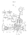
- Fig. 5 is a block diagram of an electric power steering apparatus according to a second embodiment of the present invention.
- the electric power steering apparatus is different from that of the first embodiment in that the elastic member 6 is installed between the rack shaft 8 and the rack housing 11A.
- the electric power steering apparatus is different from that of the first embodiment in that the electric motor 4 drives the pinion shaft 7 via the reduction mechanism 5 configured with the worm gear 5a and the worm wheel gear 5b and in that the column housing 10 is omitted by housing the reduction mechanism 5 and the torque sensor 12 are housed in the lid part 11B of the steering gear box 11.
- the rack housing 11A and the lid part 11B in the steering gear box 11 have different shapes from those in the first embodiment. However, these functions are the same.
- Fig. 6 is a longitudinal cross section view for describing a mechanism around the elastic member in the electric power steering apparatus shown in Fig. 5 .
- the rack shaft 8 as the steering shaft has an annular channel 8c formed in an outer circumferential surface of the rack shaft 8 into which an elastic member 6 capable of being elastically deformed is fitted as shown in Fig. 6 .
- the elastic member is a member for applying a returning force to the rack shaft 8 in the opposite direction when a rotation direction of the steering wheel 3 is changed and formed to have a rectangular shape on a longitudinal cross section in parallel to (or including) an axis AX2 of the rack shaft 8 (see Fig 8B ).
- the elastic member 6 comprises, for example, a rubber member, or a spring member and is provided between the rack shaft 8 and the rack housing 11A in such a state that an outer circumference of the elastic member 6 contacts an inner surface of the rack housing 11A.
- the elastic member 6 is installed between the rack shaft 8 and the rack housing 11A with a suitable pressure.
- a dimension in radial direction of the rack shaft 8 of the elastic member 6 is made slightly greater than a distance between the rack shaft 8 and the rack housing 11A to provide the pressure.
- the elastic member 6 is installed on a same side of the torque sensor 12 as the tires 1R, 1L and between the sliding bearing 14 and the rack gear 8a engaging with the pinion gear 7a.
- Fig. 7 is a cross section view taken along X-X line in Fig. 5 .
- the rack shaft 8 is slidably supported by a rack guide 31 in left and right directions.
- the rack guide 31 is pressurized toward the pinion gear 7a by a spring 33 so as to abut a back face of the rack shaft 8 (a face opposite to a face in which the rack gear 8a is formed).
- This configuration provides a preferable engagement between the rack gear 8a and the pinion gear 7a with allowing the rack shaft 8 to bend.
- the spring 33 is disposed between a hollow part 31a formed in the rack guide 31 and a hollow part 32a formed in a nut member 32.
- the slide bearing 14 and the pinion gear 7a are installed in the rack housing 11A with a gap in an axial direction of the rack shaft 8.
- the slide bearing 14 abuts an outer circumferential surface of the rack shaft 8.
- the pinion gear 7a is engaged with the rack gear 8a formed in an outer circumferential surface of the rack shaft 8 in corporation with the rack guide 31.
- the pinion gear 7a also serves as a bearing in addition to the slide bearing 14, and the rack shaft 8 corresponds to the steering shaft in the first embodiment regarding that the elastic member 8 is provided.
- the electric power steering apparatus 100B according to the second embodiment of the present invention is basically configured as described above. Next will be described the operation and an advantageous effect.
- Figs. 8A to 8C illustrate deformation of the elastic member 6 and displacement of the rack shaft 8 when the steering angle is small.
- Fig. 8A shows a neutral state
- Fig. 8B shows a state in which the rack shaft 8 is shifted in a left direction from the neutral state as a result of receiving a counterclockwise steering torque
- Fig. 8C shows a state in which the rack shaft 8 is shifted in a right direction from the neutral state as a result of receiving a clockwise steering torque.
- a dimension in radial direction of the rack shaft 8 of the elastic member 6 is made slightly greater than a distance between the rack shaft 8 and the rack housing 11A to provide the pressure. Accordingly, though the rack shaft 8 shifts, the elastic member 6 does not shift, but is elastically deformed (a contact surface side of the elastic member 6 with the rack shaft slightly shifts as deformation).
- the elastic member 6 restores to the original state (a shape in the neutral state as shown in Fig. 3A ).
- Figs. 9A to 9C are illustrations for describing the elastic member 6 and displacement of the rack shaft 8 when the steering angle is large.
- Fig. 9A shows a neutral state
- Figs. 9B and 9C show that the rack shaft 8 shifts in a left direction from the neutral state when a counterclockwise steering torque is applied.
- Figs. 10A to 10C are illustrations for describing the elastic member 6 and displacement of the rack shaft 8 when the steering angle is large.
- Fig. 10A shows a neutral state
- Figs. 10B and 10C show that the rack shaft 8 shifts in a right direction from the neutral state when a clockwise steering torque is applied.
- the elastic member 6 is being deformed in accordance with the rotation of the steering wheel shaft 3a.
- the elastic member 6 is not further deformed with a constant deformation quantity and rotates together with the rack shaft 8.
- the elastic member 6 restores to the original state (a shape in the neutral state as shown in Fig. 9A ).
- the restoring force is applied to the rack shaft 8, which returns the rack shaft 8 in the opposite rotation direction such that the elastic member 6 in the deformed state returns to the neutral state, so that the rack shaft 3a is returned toward the neutral state, and the steering wheel 3 is also returned toward the neutral state.
- the second embodiment as described above provides substantially the same advantageous effect as the first embodiment.
- Fig. 11 is a block diagram of an electric power steering apparatus according to a third embodiment of the present invention.
- Fig. 12A is a partial enlarged cross sectional view of a configuration around the elastic member and a supporting member of the electric power steering apparatus.
- Fig. 12B is a perspective view of the elastic member and the supporting member.
- the rack housing 11A is configured with two members.
- a hollow part 11b is provided in the rack housing 11A.
- the rack housing 11A is configured with two members, i.e., first rack housing 11A 1 and a second rack hosing 11A 2 .
- the rack housing 11A 1 as a first housing, a steel member having a hollow sleeve shape which can house a part of the rack shaft 8.
- the second rack housing 11A 2 as the second housing, installed between the first rack housing 11A 1 and a lid part 11B, is an aluminum casting member for housing and holding a part of the rack shaft 8 and the reduction mechanism, etc.
- the first rack housing 11A 1 is fixed (connected) to the second rack housing 11A 2 as a connection part by welding in a state where end parts thereof are overlapped.
- the first rack housing 11A 1 has a plurality of hollow parts 11b, 11b around the connection part 11C of the first rack housing 11A 1 and the second rack hosing 11A 2 .
- the hollow parts 11b are formed by hollowing parts of the first rack hosing 11A 1 in a direction (up and low direction) orthogonal with an axis of the rack housing 11A 1 relative to other parts.
- the hollow parts 11b are located at upper and lower parts of the first rack hosing 11A 1 in Fig. 12A one by one.
- the hollow parts 11b are disposed to oppose to each other and include a pair of side walls 11c and 11d extending along a direction orthogonal to the axial direction of the rack shaft 8 and a bottom 11e connecting one ends of the side walls 11c and 11d.
- a pair of side walls 11c, 11c function as positioning parts when the supporting member 15 is installed in the first rack housing 11A 1 . More specifically, the rack shaft 8 according to the third embodiments is easily positioned in the first housing 11A 1 by that a latch 15c is inserted into the hollow part 11b.
- the supporting member having a substantially sleeve shape is installed on an outer circumferential surface of the rack shaft 8 which is as a steering shaft.
- the supporting member 15 is a plastic member for slidably support the rack shaft 8 along an axial direction of the rack shaft 8.
- the supporting member 15 has a plurality of notches 15a, 15a extending in the axial direction of the rack shaft where the supporting member 15 is notched therethrough in a radial direction thereof (see Fig. 12A ).
- the notches 15a are formed plurally in the supporting member increases an elastic potential force in the radial direction of the supporting member 15 so that contact with the outer circumferential surface of the rack shaft 8 is enhanced. Accordingly, this causes that a force moving the rack shaft (displacement force) can be easily transmitted to the rack shaft 8, so that the elastic member attached to the supporting member can be preferably deformed when the rack shaft 8 moves.
- the latches 15c have a substantially columnar shape formed at the upper and lower parts of the supporting member 15 one by one. As shown in Fig. 12A , tips of the latches 15c, 15c are disposed in the hollow part 11b with predetermined clearances (gaps) to the side walls 11d and 11d. The clearances allow the supporting member 15 to move in the axial direction with a predetermined distance movement associated with movement of the rack shaft 8.
- the latch 15c is formed at an end of the supporting member 15 integrally. However, it is also possible to form the latch 15c separately from the supporting member 15 and is fixed to the end, in the axial direction, of the supporting member 15.
- the supporting member 15 is a member for supporting the rack shaft 8 slidably, the supporting member 15 is preferably formed with a plastic material having a relatively low friction coefficient.
- the supporting member can be also formed with a metal material such as copper to increase stiffness.
- the elastic member is fitted on an outer circumferential surface of the supporting member 15 in a channel 15b to be disposed between the supporting member 15 and the first rack housing 11A 1 .
- An inner circumferential surface of the elastic member 6 abuts the outer circumferential surface of the supporting member 15 and an outer circumferential surface of the elastic member t6 abuts an inner circumferential surface of the first rack housing 11A 1 .
- the elastic member 6 is installed between the rack shaft 8 and the rack housing 11A 1 with a suitable pressure (in a compressed state).
- a suitable pressure in a compressed state.
- a dimension in radial direction of the rack shaft 8 of the elastic member 6 is made slightly greater than a distance between the rack shaft 8 and the rack housing 11A to provide the pressure.
- a friction force F1 between the elastic member 6 and the first rack hosing 11A 1 is greater than a friction force F2 between the rack shaft 8 and the supporting member 15 (F1 > F2). Accordingly, the supporting member shifts (moves) with a shift (movement) of the rack shaft 8, so that the elastic member 6 is elastically deformed with a predetermined extent and then the movement of the supporting member along the axial direction is restricted. Accordingly, because the rack shaft 8 moves in the axial direction with slidable support by the supporting member 15, so that the rack shaft 8 can stably move.
- the status in which the elastic member 6 is elastically deformed with a predetermined extent (quantity) is that the elastic member 6 is elastically deformed such an extent that, when a rotation operation of the steering wheel 3 is changed in the rotation direction, a force returning the rack shaft 8 in the opposite direction is preferably applied to the rack shaft 8,
- this corresponds to a status in which elastic deformation of the elastic member 6 reaches a limit (a maximum friction).
- the electric power steering apparatus 100C according to the third embodiment of the present invention is basically configured as described above. Next will be described the operation and an advantageous effect.
- Figs. 13A to 13C illustrate deformation of the elastic member 6 and displacement of the rack shaft 8 when the steering angle is small.
- Fig. 13A shows a neutral state
- Fig. 13B shows a state in which the rack shaft moves in a left direction from the neutral state as a result of receiving a counterclockwise steering torque
- Fig. 13C shows a state in which the rack shaft 8 is moved in a right direction from the neutral state as a result of receiving a clockwise steering torque.
- the elastic member 6 restores to the original state (an original shape in the neutral state as shown in Fig. 13A ).
- This restoring force is applied to the rack shaft 8 as a return force applied to the rack shaft 8 in an opposite direction, so that the rack shaft 8 is returned to the neutral state and the steering wheel 3 is returned to the neutral position. It is noted that the elastic member 6 and the supporting member 15 do not restrict a movement distance of the rack shaft 8.
- Figs. 14A to 14E and 15A to 15E are illustrations for describing the elastic member 6 and displacement of the rack shaft 8 when the steering angle is large.
- Fig. 14A shows a neutral state
- Figs. 14B and 14C show that the rack shaft 8 shifts in a left direction from the neutral state when a counterclockwise steering torque is applied
- Figs. 14D and 14E show states in which the rack shaft 8 returns to the neutral state from the state in which the rack shaft 8 which has shifted in the left direction returns in response to release of the counterclockwise torque application.
- Figs. 15 to 15E are illustrations for describing deformation of the elastic member 6 and displacement of the rack shaft 8 when the steering angle is large.
- Fig. 15A shows a neutral state
- Figs. 15B and 15C show that the rack shaft 8 moves in a right direction from the neutral state when a clockwise steering torque is applied.
- Fig. 15D and 15E show states in which the rack shaft 8 returns to the neutral state from the state in which the rack shaft 8 which has shifted in the right direction returns to the neutral state in response to release of the clockwise torque application.
- Reference A in Figs. 14A to 14E and 15A to 15E is a center line being orthogonal to the axial direction of the rack shaft and passing through a center point of the latch in the axial direction of the latch in the neutral state.
- Reference B in Figs. 14A to 14E and 15A to 15E is a center line being orthogonal to the axial direction of the rack shaft and passing through a center point of the elastic member in the axial direction of the latch in the neutral state.
- the latch 15c when the elastic member 6 reaches a limit, the latch 15c does not abut the side wall 11c of the first rack housing 11A 1 , it is also possible to make the clearance between the latch 15c and the side walls 11c and 11d adjusted, so that the latch 15c abuts the side wall 11c of the first rack housing 11A 1 at the same time when the elastic deformation of the elastic member 6 reaches the limit.
- the third embodiment as described above provides substantially the same advantageous effect as the second embodiment.
- the supporting member 15 to which the elastic member 6 is fixed moves by a predetermined distance with the movement of the rack shaft 8, Accordingly, returning of the steering wheel 3 is smoothly started by the restoring force of the elastic member 6 with a quick response.
- the friction force F1 between the elastic member 6 deformed to a predetermined extent and the first rack housing 11A 1 is set to be greater than the friction force F2 between the rack shaft 8 and the supporting member 15, so that after the elastic member 6 is elastically deformed, the movement of the supporting member 15 in the axial direction is restricted. Accordingly, the rack shaft 8 can move with slidable support by the supporting member 15. Accordingly the rack shaft 8 stably moves and the steering wheel 3 can be stably returned. As a result, the vehicle can be stably controlled with a quick response in steering.
- the supporting member 15 is formed with a plastic material having a relatively low friction coefficient. This secures a smooth movement (operation) of the rack shaft 8.
- the rack housing 11A is configured by connecting the first rack housing 11A 1 to the second rack housing 11A 2 , as the connection part 11C.
- the elastic member 6 and the supporting member 15 are installed near the connection part 11C between the first rack housing 11A 1 and the second rack housing 11A 2 , which makes it easier to install the elastic member 6 and the supporting member 15 in the first rack housing 11A 1 in manufacturing, so that a work efficiency for installing the elastic member 6 and supporting member 15 increases.
- Fig. 16 is a block diagram of the modification of the electric power steering apparatus 100D according to the third embodiment.
- Fig. 17A is a partial enlarged cross sectional view of configuration around the elastic member and the supporting member of the electric power steering apparatus 100D.
- Fig. 17B is a perspective view of the elastic member and the supporting member.
- This modification is different from the third embodiment in configuration of the first rack housing 11A 1 and the second rack housing 11A 2 .
- the supporting member 15 in this modification is different from that in the third embodiment.
- one end of the second rack housing 11A 2 on the lower side extends toward a side of the slide bearing 14 by a predetermined length.
- An inner circumferential surface of the one end of the second rack hosing 11A 2 is enlarged in diameter thereof stepwise toward the side of the slide bearing 14. More specifically, as shown in Fig.
- a small diameter surface 11f having a constant inner diameter
- a middle diameter surface 11g having a constant inner diameter greater than the small diameter surface 11f
- a larger diameter surface 11h having a constant inner diameter greater than the middle diameter surface 11g
- a first step wall 11i being orthogonal with the axial direction and connecting the small diameter surface 11f to the middle diameter surface 11g
- a second step wall 11j being orthogonal with the axial direction and connecting the middle diameter surface 11g to the large diameter surface 11h, disposed in the axial direction
- the first rack housing 11A 1 and the second rack housing 11A 2 are fixed by welding in a state where the one end surface 11k, in the axial direction, of the first rack hosing 11A 1 abuts the second step wall 11j and an outer circumferential surface of the first rack housing abuts the larger diameter surface 11h of the first rack housing 11A 1 .
- an annular hollow part 11b is formed.
- the hollow part 11b is formed by being surrounded by the first step wall 11i, the middle diameter surface 11g, and the one end surface 11k in the axial direction.
- the first step wall 11i and the one end surface 11k serve as positioning parts in installing, in the first rack housing 11A 1 , the rack shaft 8 to which the supporting member 15 is attached.
- the rack shaft 8 according to this modification can be easily positioned in the first rack housing 11A 1 by inserting a latch part 15d of the supporting ember 15 (will be described later) into the hollow part 11b.
- the supporting member 15 On the outer circumferential surface of the rack shaft 8 as the steering shaft the supporting member 15 having a substantially circular sleeve shape is attached.
- the supporting member 15 is a plastic member for slidable supporting the rack shaft 8 in the axial direction.
- the supporting member 15 has a plurality of notches 15a, 15a extending in the axial direction of the rack shaft 8 where the supporting member 15 is notched therethrough in a radial direction thereof (see Fig. 17A ).
- a substantially annular latch 15d is formed of which diameter is enlarged than other parts by a predetermined length.
- An outer circumferential end of the latch 15d is disposed to have clearances in the axial direction to the first step wall 11i and the one end surface 11k in the axial direction. The clearances allow the supporting member 15 to move by a predetermined distances along the axial direction with the movement of the rack shaft 8. This allows the elastic member 6 to be elastically deformed and be restored to the original state.
- the latch 15d is formed at an end of the supporting member 15 integrally.
- the elastic member 6 is fitted on an outer circumferential surface of the supporting member 15 in a channel 15b to be disposed between the supporting member 15 and the first rack housing 11A 1 .
- An inner circumferential surface of the elastic member 6 contacts the outer circumferential surface of the supporting member 15 and an outer circumferential surface of the elastic member t6 is contacts an inner circumferential surface of the first rack housing 11A 1 .
- the elastic member 6 is installed between the rack shaft 8 and the rack housing 11A1 with an appropriate pressure.
- a dimension in radial direction of the rack shaft 8 of the elastic member 6 is made slightly greater than a distance between the rack shaft 8 and the rack housing 11A to provide the pressure.
- the friction force F1 between the elastic member 6 deformed to a predetermined extent and the first rack housing 11A 1 is set to be greater than the friction force F2 between the rack shaft 8 and the supporting member 15, so that after the elastic member 6 is elastically deformed, the movement of the supporting member 15 in the axial direction is restricted. Accordingly the rack shaft 8 moves along the axial direction with slidable support by the supporting member 15, so that the rack shaft 8 can stably move.
- the hollow part 11b and the latches 15c, 15d are provided. However, these can be omitted.
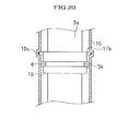
- Fig. 20 is a partial enlarged longitudinal cross section view of a part of the electric power steering apparatus according to a fourth embodiment.
- the hollow part 11b is formed in the column housing 10.
- the latch 15c is inserted in the hollow part 11b with predetermined clearances in a rotation direction (not shown in Fig 20 ) to provide a predetermined stroke of the latch 15c in the rotation direction.
- the supporting member 15 is provided between the steering shaft 3a and the elastic member 6.
- the elastic member 6 is fitted in a channel 3k. The operation is similar to the first to third embodiments.
- the elastic member 6 has a constant outer diameter over the whole circumference thereof.
- the present invention is not limited to this.
- the elastic member 6 is formed to have a plurality of notches in the outer circumference thereof in which the outer diameter varies to adjusts the (pressure force) acting thereon. This shape provides the elastic member of which the friction force acting thereon can be decreased, which may improve the steering feeling.
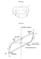
- FIG. 19 With reference to Fig. 19 , will be described an Example of the electric power steering apparatus according to the first and second embodiments ( Figs. 1 , 5 , and 11 ) in comparison with a comparative example having no elastic member regarding Lissajous' figure between the steering angle and steering torque.
- Fig. 19 illustrates Lissajous' waveforms between the steering angle and steering torque in the example and the comparative example.
- the axis of abscissa represents the steering angle ⁇ and the axis of coordinate represents the steering wheel torque Ts.
- the steering angle ⁇ on the axis of abscissa increases on a side of positive values thereof with increase in a distance to the coordinate on the right side from the origin where the axis of abscissa intersects the axis of ordinate (clockwise steering).
- the steering angle ⁇ on the axis of abscissa increases on a side of negative values thereof with increase in a distance to the coordinate on the left side from the origin (counterclockwise steering).
- the steering wheel torque Ts on the axis of ordinate increases on a side of positive values thereof with increase in a distance to the coordinate on the upper side from the origin.
- the steering wheel torque Ts on the axis of ordinate increases on a side of positive values thereof with increase in a distance to the coordinate on the upper side from the origin.
- the electric power steering apparatus having an elastic member provides a more rapid return when the turning direction of the steering wheel 3 is switched than the comparison example having no elastic member 6.
- installation of the elastic member 6 in the electric power steering apparatus increases a responsibility in switching of the turning direction of the steering wheel 3.
- an elastic member disposed between the steering shaft and the housing, configured to be elastically deformed in accordance with rotation or displacement in a vehicle width direction, of the steering shaft.
- At least two bearings disposed with a gap in an axial direction of the steering shaft, are configured to support the steering shaft.
- the elastic member is disposed between the bearings.
- a supporting member may be disposed between the steering shaft and the elastic member and configured to be displaced by a rotation of a predetermined angle or predetermined distance in accordance with the rotation or a displacement, in the width direction of the vehicle, of the steering shaft with slidable support for the steering shaft.
- the elastic member is fixed to the supporting member and abuts the housing.
Landscapes
- Engineering & Computer Science (AREA)
- Chemical & Material Sciences (AREA)
- Combustion & Propulsion (AREA)
- Transportation (AREA)
- Mechanical Engineering (AREA)
- Power Steering Mechanism (AREA)
Applications Claiming Priority (1)
| Application Number | Priority Date | Filing Date | Title |
|---|---|---|---|
| JP2010134342 | 2010-06-11 |
Publications (2)
| Publication Number | Publication Date |
|---|---|
| EP2394884A1 true EP2394884A1 (fr) | 2011-12-14 |
| EP2394884B1 EP2394884B1 (fr) | 2014-01-29 |
Family
ID=44454114
Family Applications (1)
| Application Number | Title | Priority Date | Filing Date |
|---|---|---|---|
| EP20110169431 Not-in-force EP2394884B1 (fr) | 2010-06-11 | 2011-06-10 | Appareil de direction assistée électrique |
Country Status (1)
| Country | Link |
|---|---|
| EP (1) | EP2394884B1 (fr) |
Cited By (2)
| Publication number | Priority date | Publication date | Assignee | Title |
|---|---|---|---|---|
| CN112758170A (zh) * | 2021-01-28 | 2021-05-07 | 上海海事大学 | 一种汽车转向杆的稳固装置 |
| CN112874627A (zh) * | 2019-11-29 | 2021-06-01 | 比亚迪股份有限公司 | 车辆和车辆转向方法 |
Citations (4)
| Publication number | Priority date | Publication date | Assignee | Title |
|---|---|---|---|---|
| DE4440725A1 (de) * | 1994-11-15 | 1996-05-23 | Schaeffler Waelzlager Kg | Lageranordnung zur spielfreien Einstellung einer Welle, insbesondere einer Lenkwelle in einer Lenksäule |
| GB2339610A (en) * | 1998-07-16 | 2000-02-02 | Nsk Ltd | Universal Joint |
| JP2003019967A (ja) | 2001-07-06 | 2003-01-21 | Nippon Yusoki Co Ltd | 車両の操舵装置 |
| JP2006264621A (ja) | 2005-03-25 | 2006-10-05 | Honda Motor Co Ltd | 電動パワーステアリング装置 |
-
2011
- 2011-06-10 EP EP20110169431 patent/EP2394884B1/fr not_active Not-in-force
Patent Citations (4)
| Publication number | Priority date | Publication date | Assignee | Title |
|---|---|---|---|---|
| DE4440725A1 (de) * | 1994-11-15 | 1996-05-23 | Schaeffler Waelzlager Kg | Lageranordnung zur spielfreien Einstellung einer Welle, insbesondere einer Lenkwelle in einer Lenksäule |
| GB2339610A (en) * | 1998-07-16 | 2000-02-02 | Nsk Ltd | Universal Joint |
| JP2003019967A (ja) | 2001-07-06 | 2003-01-21 | Nippon Yusoki Co Ltd | 車両の操舵装置 |
| JP2006264621A (ja) | 2005-03-25 | 2006-10-05 | Honda Motor Co Ltd | 電動パワーステアリング装置 |
Cited By (3)
| Publication number | Priority date | Publication date | Assignee | Title |
|---|---|---|---|---|
| CN112874627A (zh) * | 2019-11-29 | 2021-06-01 | 比亚迪股份有限公司 | 车辆和车辆转向方法 |
| CN112874627B (zh) * | 2019-11-29 | 2022-09-06 | 比亚迪股份有限公司 | 车辆和车辆转向方法 |
| CN112758170A (zh) * | 2021-01-28 | 2021-05-07 | 上海海事大学 | 一种汽车转向杆的稳固装置 |
Also Published As
| Publication number | Publication date |
|---|---|
| EP2394884B1 (fr) | 2014-01-29 |
Similar Documents
| Publication | Publication Date | Title |
|---|---|---|
| US8556023B2 (en) | Electric power steering apparatus | |
| US7472773B2 (en) | Electrically driven power steering apparatus | |
| US7219761B2 (en) | Motor-operated power steering apparatus | |
| EP2019020B1 (fr) | Appareil de direction assistée doté d'un dispositif de détection de défaillance pour capteurs d'angle de rotation | |
| JP4783352B2 (ja) | ラックアンドピニオン式電動パワーステアリング装置 | |
| EP1291264A2 (fr) | Dispositif et procédé de mesure de position absolue | |
| JP4979801B2 (ja) | ウォーム減速機及び電動式パワーステアリング装置 | |
| US12454311B2 (en) | Steer-by-wire steering device and method for controlling the same | |
| EP2444298B1 (fr) | Système de direction de véhicule à moteur | |
| KR102693164B1 (ko) | 스티어 바이 와이어식 조향장치 | |
| US12319364B2 (en) | Steer-by-wire steering apparatus | |
| US12473009B2 (en) | Steer by wire type steering apparatus | |
| EP2394884B1 (fr) | Appareil de direction assistée électrique | |
| JP2009171736A (ja) | 電動モータ | |
| JP2009202740A (ja) | パワーステアリング装置 | |
| US12454305B2 (en) | Steer by wire type steering apparatus | |
| JP5594523B2 (ja) | 車両用操舵装置 | |
| US20160200345A1 (en) | Steering apparatus | |
| JP2006168515A (ja) | 車両用ステアリングシステム | |
| EP2177420B1 (fr) | Dispositif de transmission de force de direction pour véhicule | |
| CN114379641A (zh) | 检测车轮传动装置的错误的转向装置及确定错误的方法 | |
| JPH10305778A (ja) | パワーステアリング装置 | |
| US12391310B2 (en) | Steering control device and method | |
| KR20120139968A (ko) | 토크 센서 시스템 및 이를 구비한 전동식 동력 보조 조향장치 | |
| JP4593318B2 (ja) | 電動ステアリング装置 |
Legal Events
| Date | Code | Title | Description |
|---|---|---|---|
| 17P | Request for examination filed |
Effective date: 20110610 |
|
| AK | Designated contracting states |
Kind code of ref document: A1 Designated state(s): AL AT BE BG CH CY CZ DE DK EE ES FI FR GB GR HR HU IE IS IT LI LT LU LV MC MK MT NL NO PL PT RO RS SE SI SK SM TR |
|
| AX | Request for extension of the european patent |
Extension state: BA ME |
|
| PUAI | Public reference made under article 153(3) epc to a published international application that has entered the european phase |
Free format text: ORIGINAL CODE: 0009012 |
|
| 17Q | First examination report despatched |
Effective date: 20121008 |
|
| GRAP | Despatch of communication of intention to grant a patent |
Free format text: ORIGINAL CODE: EPIDOSNIGR1 |
|
| INTG | Intention to grant announced |
Effective date: 20130912 |
|
| GRAS | Grant fee paid |
Free format text: ORIGINAL CODE: EPIDOSNIGR3 |
|
| GRAA | (expected) grant |
Free format text: ORIGINAL CODE: 0009210 |
|
| AK | Designated contracting states |
Kind code of ref document: B1 Designated state(s): AL AT BE BG CH CY CZ DE DK EE ES FI FR GB GR HR HU IE IS IT LI LT LU LV MC MK MT NL NO PL PT RO RS SE SI SK SM TR |
|
| REG | Reference to a national code |
Ref country code: GB Ref legal event code: FG4D |
|
| REG | Reference to a national code |
Ref country code: CH Ref legal event code: EP |
|
| REG | Reference to a national code |
Ref country code: AT Ref legal event code: REF Ref document number: 651438 Country of ref document: AT Kind code of ref document: T Effective date: 20140215 |
|
| REG | Reference to a national code |
Ref country code: IE Ref legal event code: FG4D |
|
| REG | Reference to a national code |
Ref country code: DE Ref legal event code: R096 Ref document number: 602011004848 Country of ref document: DE Effective date: 20140313 |
|
| REG | Reference to a national code |
Ref country code: AT Ref legal event code: MK05 Ref document number: 651438 Country of ref document: AT Kind code of ref document: T Effective date: 20140129 |
|
| REG | Reference to a national code |
Ref country code: NL Ref legal event code: VDEP Effective date: 20140129 |
|
| REG | Reference to a national code |
Ref country code: LT Ref legal event code: MG4D |
|
| PG25 | Lapsed in a contracting state [announced via postgrant information from national office to epo] |
Ref country code: NO Free format text: LAPSE BECAUSE OF FAILURE TO SUBMIT A TRANSLATION OF THE DESCRIPTION OR TO PAY THE FEE WITHIN THE PRESCRIBED TIME-LIMIT Effective date: 20140429 Ref country code: IS Free format text: LAPSE BECAUSE OF FAILURE TO SUBMIT A TRANSLATION OF THE DESCRIPTION OR TO PAY THE FEE WITHIN THE PRESCRIBED TIME-LIMIT Effective date: 20140529 Ref country code: LT Free format text: LAPSE BECAUSE OF FAILURE TO SUBMIT A TRANSLATION OF THE DESCRIPTION OR TO PAY THE FEE WITHIN THE PRESCRIBED TIME-LIMIT Effective date: 20140129 |
|
| PG25 | Lapsed in a contracting state [announced via postgrant information from national office to epo] |
Ref country code: NL Free format text: LAPSE BECAUSE OF FAILURE TO SUBMIT A TRANSLATION OF THE DESCRIPTION OR TO PAY THE FEE WITHIN THE PRESCRIBED TIME-LIMIT Effective date: 20140129 Ref country code: FI Free format text: LAPSE BECAUSE OF FAILURE TO SUBMIT A TRANSLATION OF THE DESCRIPTION OR TO PAY THE FEE WITHIN THE PRESCRIBED TIME-LIMIT Effective date: 20140129 Ref country code: PT Free format text: LAPSE BECAUSE OF FAILURE TO SUBMIT A TRANSLATION OF THE DESCRIPTION OR TO PAY THE FEE WITHIN THE PRESCRIBED TIME-LIMIT Effective date: 20140529 Ref country code: SE Free format text: LAPSE BECAUSE OF FAILURE TO SUBMIT A TRANSLATION OF THE DESCRIPTION OR TO PAY THE FEE WITHIN THE PRESCRIBED TIME-LIMIT Effective date: 20140129 Ref country code: ES Free format text: LAPSE BECAUSE OF FAILURE TO SUBMIT A TRANSLATION OF THE DESCRIPTION OR TO PAY THE FEE WITHIN THE PRESCRIBED TIME-LIMIT Effective date: 20140129 Ref country code: CY Free format text: LAPSE BECAUSE OF FAILURE TO SUBMIT A TRANSLATION OF THE DESCRIPTION OR TO PAY THE FEE WITHIN THE PRESCRIBED TIME-LIMIT Effective date: 20140129 Ref country code: AT Free format text: LAPSE BECAUSE OF FAILURE TO SUBMIT A TRANSLATION OF THE DESCRIPTION OR TO PAY THE FEE WITHIN THE PRESCRIBED TIME-LIMIT Effective date: 20140129 |
|
| PGFP | Annual fee paid to national office [announced via postgrant information from national office to epo] |
Ref country code: DE Payment date: 20140530 Year of fee payment: 4 |
|
| PG25 | Lapsed in a contracting state [announced via postgrant information from national office to epo] |
Ref country code: RS Free format text: LAPSE BECAUSE OF FAILURE TO SUBMIT A TRANSLATION OF THE DESCRIPTION OR TO PAY THE FEE WITHIN THE PRESCRIBED TIME-LIMIT Effective date: 20140129 Ref country code: LV Free format text: LAPSE BECAUSE OF FAILURE TO SUBMIT A TRANSLATION OF THE DESCRIPTION OR TO PAY THE FEE WITHIN THE PRESCRIBED TIME-LIMIT Effective date: 20140129 Ref country code: HR Free format text: LAPSE BECAUSE OF FAILURE TO SUBMIT A TRANSLATION OF THE DESCRIPTION OR TO PAY THE FEE WITHIN THE PRESCRIBED TIME-LIMIT Effective date: 20140129 Ref country code: BE Free format text: LAPSE BECAUSE OF FAILURE TO SUBMIT A TRANSLATION OF THE DESCRIPTION OR TO PAY THE FEE WITHIN THE PRESCRIBED TIME-LIMIT Effective date: 20140129 |
|
| REG | Reference to a national code |
Ref country code: DE Ref legal event code: R097 Ref document number: 602011004848 Country of ref document: DE |
|
| PG25 | Lapsed in a contracting state [announced via postgrant information from national office to epo] |
Ref country code: CZ Free format text: LAPSE BECAUSE OF FAILURE TO SUBMIT A TRANSLATION OF THE DESCRIPTION OR TO PAY THE FEE WITHIN THE PRESCRIBED TIME-LIMIT Effective date: 20140129 Ref country code: DK Free format text: LAPSE BECAUSE OF FAILURE TO SUBMIT A TRANSLATION OF THE DESCRIPTION OR TO PAY THE FEE WITHIN THE PRESCRIBED TIME-LIMIT Effective date: 20140129 Ref country code: EE Free format text: LAPSE BECAUSE OF FAILURE TO SUBMIT A TRANSLATION OF THE DESCRIPTION OR TO PAY THE FEE WITHIN THE PRESCRIBED TIME-LIMIT Effective date: 20140129 Ref country code: RO Free format text: LAPSE BECAUSE OF FAILURE TO SUBMIT A TRANSLATION OF THE DESCRIPTION OR TO PAY THE FEE WITHIN THE PRESCRIBED TIME-LIMIT Effective date: 20140129 |
|
| PG25 | Lapsed in a contracting state [announced via postgrant information from national office to epo] |
Ref country code: PL Free format text: LAPSE BECAUSE OF FAILURE TO SUBMIT A TRANSLATION OF THE DESCRIPTION OR TO PAY THE FEE WITHIN THE PRESCRIBED TIME-LIMIT Effective date: 20140129 Ref country code: SK Free format text: LAPSE BECAUSE OF FAILURE TO SUBMIT A TRANSLATION OF THE DESCRIPTION OR TO PAY THE FEE WITHIN THE PRESCRIBED TIME-LIMIT Effective date: 20140129 |
|
| PGFP | Annual fee paid to national office [announced via postgrant information from national office to epo] |
Ref country code: FR Payment date: 20140619 Year of fee payment: 4 |
|
| PLBE | No opposition filed within time limit |
Free format text: ORIGINAL CODE: 0009261 |
|
| STAA | Information on the status of an ep patent application or granted ep patent |
Free format text: STATUS: NO OPPOSITION FILED WITHIN TIME LIMIT |
|
| 26N | No opposition filed |
Effective date: 20141030 |
|
| PG25 | Lapsed in a contracting state [announced via postgrant information from national office to epo] |
Ref country code: MC Free format text: LAPSE BECAUSE OF FAILURE TO SUBMIT A TRANSLATION OF THE DESCRIPTION OR TO PAY THE FEE WITHIN THE PRESCRIBED TIME-LIMIT Effective date: 20140129 Ref country code: LU Free format text: LAPSE BECAUSE OF FAILURE TO SUBMIT A TRANSLATION OF THE DESCRIPTION OR TO PAY THE FEE WITHIN THE PRESCRIBED TIME-LIMIT Effective date: 20140610 |
|
| REG | Reference to a national code |
Ref country code: CH Ref legal event code: PL |
|
| REG | Reference to a national code |
Ref country code: DE Ref legal event code: R097 Ref document number: 602011004848 Country of ref document: DE Effective date: 20141030 |
|
| REG | Reference to a national code |
Ref country code: IE Ref legal event code: MM4A |
|
| PG25 | Lapsed in a contracting state [announced via postgrant information from national office to epo] |
Ref country code: CH Free format text: LAPSE BECAUSE OF NON-PAYMENT OF DUE FEES Effective date: 20140630 Ref country code: LI Free format text: LAPSE BECAUSE OF NON-PAYMENT OF DUE FEES Effective date: 20140630 Ref country code: IE Free format text: LAPSE BECAUSE OF NON-PAYMENT OF DUE FEES Effective date: 20140610 |
|
| PG25 | Lapsed in a contracting state [announced via postgrant information from national office to epo] |
Ref country code: SI Free format text: LAPSE BECAUSE OF FAILURE TO SUBMIT A TRANSLATION OF THE DESCRIPTION OR TO PAY THE FEE WITHIN THE PRESCRIBED TIME-LIMIT Effective date: 20140129 |
|
| REG | Reference to a national code |
Ref country code: DE Ref legal event code: R119 Ref document number: 602011004848 Country of ref document: DE |
|
| GBPC | Gb: european patent ceased through non-payment of renewal fee |
Effective date: 20150610 |
|
| PG25 | Lapsed in a contracting state [announced via postgrant information from national office to epo] |
Ref country code: MT Free format text: LAPSE BECAUSE OF FAILURE TO SUBMIT A TRANSLATION OF THE DESCRIPTION OR TO PAY THE FEE WITHIN THE PRESCRIBED TIME-LIMIT Effective date: 20140129 |
|
| REG | Reference to a national code |
Ref country code: FR Ref legal event code: ST Effective date: 20160229 |
|
| PG25 | Lapsed in a contracting state [announced via postgrant information from national office to epo] |
Ref country code: GB Free format text: LAPSE BECAUSE OF NON-PAYMENT OF DUE FEES Effective date: 20150610 Ref country code: SM Free format text: LAPSE BECAUSE OF FAILURE TO SUBMIT A TRANSLATION OF THE DESCRIPTION OR TO PAY THE FEE WITHIN THE PRESCRIBED TIME-LIMIT Effective date: 20140129 Ref country code: DE Free format text: LAPSE BECAUSE OF NON-PAYMENT OF DUE FEES Effective date: 20160101 |
|
| PG25 | Lapsed in a contracting state [announced via postgrant information from national office to epo] |
Ref country code: FR Free format text: LAPSE BECAUSE OF NON-PAYMENT OF DUE FEES Effective date: 20150630 |
|
| PG25 | Lapsed in a contracting state [announced via postgrant information from national office to epo] |
Ref country code: GR Free format text: LAPSE BECAUSE OF FAILURE TO SUBMIT A TRANSLATION OF THE DESCRIPTION OR TO PAY THE FEE WITHIN THE PRESCRIBED TIME-LIMIT Effective date: 20140430 Ref country code: IT Free format text: LAPSE BECAUSE OF FAILURE TO SUBMIT A TRANSLATION OF THE DESCRIPTION OR TO PAY THE FEE WITHIN THE PRESCRIBED TIME-LIMIT Effective date: 20140129 Ref country code: BG Free format text: LAPSE BECAUSE OF FAILURE TO SUBMIT A TRANSLATION OF THE DESCRIPTION OR TO PAY THE FEE WITHIN THE PRESCRIBED TIME-LIMIT Effective date: 20140129 |
|
| PG25 | Lapsed in a contracting state [announced via postgrant information from national office to epo] |
Ref country code: TR Free format text: LAPSE BECAUSE OF FAILURE TO SUBMIT A TRANSLATION OF THE DESCRIPTION OR TO PAY THE FEE WITHIN THE PRESCRIBED TIME-LIMIT Effective date: 20140129 Ref country code: HU Free format text: LAPSE BECAUSE OF FAILURE TO SUBMIT A TRANSLATION OF THE DESCRIPTION OR TO PAY THE FEE WITHIN THE PRESCRIBED TIME-LIMIT; INVALID AB INITIO Effective date: 20110610 |
|
| PG25 | Lapsed in a contracting state [announced via postgrant information from national office to epo] |
Ref country code: MK Free format text: LAPSE BECAUSE OF FAILURE TO SUBMIT A TRANSLATION OF THE DESCRIPTION OR TO PAY THE FEE WITHIN THE PRESCRIBED TIME-LIMIT Effective date: 20140129 |
|
| PG25 | Lapsed in a contracting state [announced via postgrant information from national office to epo] |
Ref country code: AL Free format text: LAPSE BECAUSE OF FAILURE TO SUBMIT A TRANSLATION OF THE DESCRIPTION OR TO PAY THE FEE WITHIN THE PRESCRIBED TIME-LIMIT Effective date: 20140129 |