EP2394843A2 - Système de suspension pneumatique pour véhicules et procédé d'amortissement pneumatique de pièces de véhicules - Google Patents
Système de suspension pneumatique pour véhicules et procédé d'amortissement pneumatique de pièces de véhicules Download PDFInfo
- Publication number
- EP2394843A2 EP2394843A2 EP11168453A EP11168453A EP2394843A2 EP 2394843 A2 EP2394843 A2 EP 2394843A2 EP 11168453 A EP11168453 A EP 11168453A EP 11168453 A EP11168453 A EP 11168453A EP 2394843 A2 EP2394843 A2 EP 2394843A2
- Authority
- EP
- European Patent Office
- Prior art keywords
- air
- air spring
- suspension system
- control device
- spring
- Prior art date
- Legal status (The legal status is an assumption and is not a legal conclusion. Google has not performed a legal analysis and makes no representation as to the accuracy of the status listed.)
- Granted
Links
Images


Classifications
-
- B—PERFORMING OPERATIONS; TRANSPORTING
- B60—VEHICLES IN GENERAL
- B60N—SEATS SPECIALLY ADAPTED FOR VEHICLES; VEHICLE PASSENGER ACCOMMODATION NOT OTHERWISE PROVIDED FOR
- B60N2/00—Seats specially adapted for vehicles; Arrangement or mounting of seats in vehicles
- B60N2/50—Seat suspension devices
- B60N2/501—Seat suspension devices actively controlled suspension, e.g. electronic control
-
- B—PERFORMING OPERATIONS; TRANSPORTING
- B60—VEHICLES IN GENERAL
- B60N—SEATS SPECIALLY ADAPTED FOR VEHICLES; VEHICLE PASSENGER ACCOMMODATION NOT OTHERWISE PROVIDED FOR
- B60N2/00—Seats specially adapted for vehicles; Arrangement or mounting of seats in vehicles
- B60N2/50—Seat suspension devices
- B60N2/502—Seat suspension devices attached to the base of the seat
-
- B—PERFORMING OPERATIONS; TRANSPORTING
- B60—VEHICLES IN GENERAL
- B60N—SEATS SPECIALLY ADAPTED FOR VEHICLES; VEHICLE PASSENGER ACCOMMODATION NOT OTHERWISE PROVIDED FOR
- B60N2/00—Seats specially adapted for vehicles; Arrangement or mounting of seats in vehicles
- B60N2/50—Seat suspension devices
- B60N2/505—Adjustable suspension including height adjustment
-
- B—PERFORMING OPERATIONS; TRANSPORTING
- B60—VEHICLES IN GENERAL
- B60N—SEATS SPECIALLY ADAPTED FOR VEHICLES; VEHICLE PASSENGER ACCOMMODATION NOT OTHERWISE PROVIDED FOR
- B60N2/00—Seats specially adapted for vehicles; Arrangement or mounting of seats in vehicles
- B60N2/50—Seat suspension devices
- B60N2/506—Seat guided by rods
- B60N2/508—Scissors-like structure
-
- B—PERFORMING OPERATIONS; TRANSPORTING
- B60—VEHICLES IN GENERAL
- B60N—SEATS SPECIALLY ADAPTED FOR VEHICLES; VEHICLE PASSENGER ACCOMMODATION NOT OTHERWISE PROVIDED FOR
- B60N2/00—Seats specially adapted for vehicles; Arrangement or mounting of seats in vehicles
- B60N2/50—Seat suspension devices
- B60N2/52—Seat suspension devices using fluid means
- B60N2/525—Seat suspension devices using fluid means using gas
Definitions
- the invention relates to a pneumatic suspension system for vehicles with at least a first and a second part, wherein both parts are mounted by means of at least one air spring vibrationally movable and pneumatically resilient to each other, according to the preamble of claim 1 and a method for pneumatic springs of vehicle parts according to the preamble of Claim 10.
- Pneumatic suspension systems for vehicles as well as methods for the pneumatic springing of vehicle parts are known from various areas of a vehicle.
- Pneumatic suspension systems are used in particular in pneumatically sprung vehicle seats, pneumatically sprung vehicle cabins and pneumatically sprung chassis of vehicles.
- the setting of a relatively stable level position of the vehicle seat is usually controlled in such air-suspension vehicle seats by means of a so-called open control.
- a strong compression of the air spring due to a strong initiation of a vibrational movement when driving over a driving surface elevation air is supplied, whereas when a pulling apart of the air spring during a strong initiation of vibration due to the passage of a trough in the roadway air is removed from the air spring.
- Another known counteracting measure is the adjustment of the vehicle seat in its height, so that the suspension system is again arranged in a middle position with respect to the available spring travel.
- this can in turn mean that the driver, if it is a small person, can no longer reliably operate the vehicle, since brake pedals, clutch pedals and the like can no longer be reliably reached with the foot.
- the present invention seeks to provide a pneumatic suspension system for vehicles and a method for pneumatic springs of vehicle parts available, in spite of a limited available Restfederweges the suspension system and in particular a pneumatic spring used for air suspension in the vehicle seated person experiences a high level of comfort.
- An essential point of the invention is that in a pneumatic suspension system for vehicles with at least a first and a second part, wherein both parts are mounted by means of at least one air spring vibrationally movable and pneumatically resilient to each other and a first control device for supplying and discharging air in and disposed from the air spring, which performs the discharge of air after a first Hubend Geb the suspension system, in which the air spring is in a compressed state, has been reached, and which performs the supply of air, after a second Hubend Scheme the suspension system in which the air spring is in an exploded state has been reached, a second control means for supplying air into the air spring and for switching off the discharge of air in the air spring for a predeterminable first period of time is arranged after a first ers ter Hubendanschlag has been achieved in the first Hubend Scheme.
- a third control means for removing air from the air spring and for switching off the supply of air in the air spring for a predeterminable second period of time after a first Hubendanschlag in the second Hubend Scheme has been achieved for the first time be arranged.
- the second control device which may be arranged separately or integrated in the first control device as well as the third control device, air in the air spring, at the same time the usual discharge of air from the air spring is turned off , This happens only during a predeterminable time period, that is to say during the predeterminable first period of time after the first stroke end stop has been reached, in order to limit this first time span during which strong oscillatory movements are initiated, damping the oscillation movement of the suspension system, in this case in a diverging air spring to obtain.
- air is then taken from the air spring by means of the third control device when reaching a top-side Hubendanschlages of the air spring, instead of supplying air, as would be the case with a normal waveform without the introduction of strong vibrations. This takes place until the predeterminable second time period has expired.
- This discharge of air by means of the third control means during a downward movement of the vehicle seat is performed alternately with the supply of air by the second control means during an upward movement of the vehicle seat until the respective first and second time periods have elapsed Duration depends on how long the initiation of the strong vibration movements takes place.
- the shut-off of the discharge of air during the supply of air by the second control means and the first control means as well as the shut-off of the supply of air by the first control means during the discharge of air by the third control means and by the first control means of the oscillation frequency the oscillating moving parts controlled. That is, as soon as, for example, an oscillation frequency of the suspension system and thus the swingingly mutually moving parts of more than 0.5 Hz occurs, a shutdown of the discharge of the air takes place after reaching the lower Hubendanschlages the vehicle seat. After reaching the upper Hubendanschlages, however, the supply of air is switched off just above a certain oscillation frequency of, for example, 0.5 Hz. The consequence of this is that after reaching the Hubendaneaun the residual spring travel increase and that until such time as no more stroke stops are touched. This results in the necessary for optimal vibration movement of the suspension system with the best possible avoidance of reaching the Hubendaneau residual spring travel.
- the second or third control device can also be used alone, ie without the third or the second control device. This has the consequence that a Restfederwegoptimierung is obtained only after reaching a lower Hubendanschlages or after reaching an upper Hubendanschlages.
- the resetting to the normal vibration control process in which only the first control means, but not directly the second and third control means are active, can in turn be made dependent on the vibration frequency of the vibration-movable parts.
- a reset frequency is performed at less than 0.8 Hz.
- the second control device to a first control valve preferably a 2/2-way valve, which in an exhaust duct, the Air spring connects to the first control device
- the third control device may comprise a second control valve, preferably a 2/2-way valve, which is arranged in an air supply line which connects the air spring with the first control device for switching on and off of the supply of air in the air spring.
- the second and the third control valve in each case by means of at least one movable element, which is movable by one of the vibration-movable elements, switchable.
- Each movable member is connected to a motion delay member for retarding the movable member against a spring loading force to a home position during the first and second time periods, respectively.
- the movable member is formed as a rack and the movement delay member is formed as a rotatable gear, which cooperates with the rack and can be acted upon by a predeterminable torque, wherein the torque of, for example, 10 Ncm only in a first rotational direction of the gear in the the rack moves from a deflection position to the starting position, acts.
- a torque of 0 Ncm is set so that the start of the first and second periods by moving the rack and simultaneously switching the first and / or second Control valve immediately after actuation by a vibration movable part, which is located shortly before the Hubendanschlag the suspension system takes place.
- an oscillation frequency switching means from a predeterminable oscillation frequency of the oscillatory moving parts performs the switching off of the discharge of air from the air spring at the beginning of the first period and the switching off of the supply of air in the air spring at the beginning of the second period.
- the suspension system according to the invention and the method according to the invention can be applied, for example, to vehicle seats, wherein the first part is a vehicle seat upper part and the second part is a vehicle seat bottom. Alternatively, it may be applied to vehicle cabins, the first part being the vehicle cab itself and the second part being, for example, the vehicle chassis. Likewise, it can be applied to chassis of vehicles, wherein the vehicle frame is the first part and the suspension is the second part.
- a method for pneumatic springs of vehicle parts having at least a first and a second part, wherein both parts by means of at least one air spring to move oscillating to each other and are mounted pneumatically resilient to each other, wherein a first control means in and out of the air spring and discharging air which performs after a first Hubend Geb the suspension system in which the air spring is in a compressed state, has been reached, and which performs the supply of air, after a second Hubend Scheme the suspension system in which the Air spring is located in an exploded state, has been achieved wherein air is supplied into the air spring by means of a second control device and the removal of air from the air spring is switched off during a predeterminable first period of time after a first stroke end stop has first been reached in the first stroke end region, and / or by means of a third control device for a predeterminable second time period air is discharged from the air spring and the supply of air is switched off in the air spring after a second Hubendanschlag has been achieved in the second Hubend
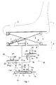
- Fig. 1 is shown in a schematic representation of the basic principle of the pneumatic suspension system based on a vehicle seat.
- the vehicle seat has a backrest 1 and a cushion seat part 2, which is arranged on an upper vehicle seat part 3.
- the vehicle seat part 3 is swingably mounted with respect to a lower vehicle seat part 4 pneumatically suspended and can oscillate up and down, as shown by the double arrow 9.
- the upper vehicle seat part 3 is spaced from the lower vehicle seat part 4.
- An air spring 8 is disposed between the scissor arm 5 and the lower vehicle seat part 4.
- An additional damper 7 is fastened on the one hand to the lower vehicle seat part 4 and on the other hand to the scissor arm 6.
- a first control device 10 serves to supply and discharge air to the air spring 8.
- the first control device 10 consists of a housing 11 with a piston-like element 12 arranged therein, which can be displaced in the longitudinal direction, as represented by the double arrow 13.
- the piston-like element 12 is comprised of two spaced-apart sealing elements 14 and 15 and sealingly mounted relative to the housing.
- Another input and output 18 serves to supply and remove air by means of the line 19 to and from the air spring eighth
- air can be supplied, air can be discharged or a closed system without air supply and discharge can be set. If, for example, the piston-like element 12 is displaced to the right, then air can be discharged from the air spring 8 into the inlet and outlet 18 via the line 19 and escape via the outlet 17. If, however, the piston-like element 12 is displaced to the left, then air 16a can be conducted via the inlet 16 past the sealing element 14 via the inlet and outlet 18 and the line 19 into the air spring 8.
- a second control device 20 essentially has a 2/2 control valve 21, which is arranged within an exhaust air line 22.
- the control valve 21 is deflected by means of the heel in the rack 23 and can thereby either interrupt the exhaust duct 22 or switch to passage.
- a gear is connected as a movement delay member, conventionally known as a honey motor, designated by the reference numeral 26.
- This gear can be moved according to the double arrow 27 to the left and right simultaneously with the displacement of the rack 23 by the teeth of the rack 23, which engage in the teeth of the gear 26, the gear 26 rotate.
- a third control device 30 is constructed similar to the second control device. Again, a control valve in the form of a 2/2-way control valve 31 is provided, which is arranged within a supply air line 32 in order to interrupt or turn on.
- a rack 33 which can be reciprocated along the double arrow 34 and, as well as the rack 23 with the spring 25 can be spring-loaded by the spring 35, as soon as a shift takes place, is arranged.
- the rack 33 in turn cooperates with a gear 36, which is designed as a time delay element and can be rotated along the double arrow 37.
- Both the gear 26 and the gear 36 have a torque of, for example, 10 Ncm, when the gear moves so that the rack 23, 33 is moved back to its original position, ie towards the center of the image.
- the torque counteracts the spring 25, 35, which is stretched by deflection of the rack 23, 33.
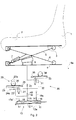
- Fig. 2 is also shown in a schematic representation of the basic principle of the pneumatic suspension system according to the invention according to an embodiment of the invention, this representation represents a state of the control devices and the vehicle seat, which is taken after first reaching a lower Hubendanschlages.
- This illustration shows that the vehicle seat is deflected downwards, as can be seen clearly by the compressed or compressed air spring 8.
- the air spring 8 or another part of the vehicle seat has already reached a Hubendanschlag, whereupon shortly after reaching the Hubendanschlages the second control device 20 is activated. This happens because the rack 23 has been deflected upon reaching the Hubendanschlages and has moved in the direction of arrow 24a. As a result, the control valve 21 is deflected, which has an interruption of the exhaust air line 22 result. This is clearly shown in the illustration.
- the third control device is unchanged so far.
- the piston-like element 12 is now shifted to the left, so that air 16a can flow out of the input and output 18 through the input 16 and flow through the line 19 and the valve 40 and the air supply line 32 in the air spring 8 can.
- the exhaust air line is interrupted and the supply air line 32 is turned on.
- Fig. 3 the basic principle of the pneumatic suspension system according to the invention with associated vehicle seat is shown in a further state after reaching the upper Hubendanschlages. Identical and equivalent parts are provided with the same reference numerals.
- the arrow 34a shows the movement of the rack for the deflection, ie for the movement in a deflection position and the arrow 37a shows the rotational movement of the gear 36, which is associated with the deflection movement of the rack 33.
- the period of time during which the honey-making motor allows the toothed rod 23, 33 to return to its initial position and thus to switch the valves 31, 21 into a switching-through mode is preferably adjustable between 0 and 10 seconds.
- Fig. 4 is shown in a schematic representation of the components of the spring system according to the invention. Identical and equivalent parts are provided with the same reference numerals.
- This illustration clearly shows that the positioning of the first control device 10 preferably takes place between the upper vehicle seat part 3 and the scissor arm 6.
- this illustration shows that the second and third control device 20 and 30 preferably in the form of separate components and subsequently can be arranged, said components z. B. with a roller-like element 6a, which is connected to the scissor arm 6, can interact, in which the roller-like element 6a is rolled to the left or to the right depending on the deflection of the scissor arm and instantaneous height adjustment of the vehicle seat.
- This roller-like element 6a will actuate an actuating element 20a, which interacts with the toothed rack 23, in the case of a predefinable stroke end stop in the second control device 20.
- the roller-like element 6a Upon reaching a lower Hubendanschlages the roller-like element 6a will interact with an actuator 30a of the third control device, which interacts with the rack 33.
- Fig. 5 is a schematic diagram of the waveform of the pneumatic suspension system according to the invention shown upon reaching a lower Hubendanschlages the suspension system.
- a vibration 50 which the pneumatic suspension system performs takes place above and below a normally existing zero line 51.
- a line 52 is reached with an upward deflection of the suspension system, normally takes place the discharge of air from the air spring instead of acting against the oscillatory motion in the direction of the zero line 51.
- a line 53 is exceeded, the supply of air takes place in order to counteract the oscillatory movement in the direction of the zero line 51. This applies to a normally occurring vibration, ie without reaching a Hubendanschlages.
- Such supplying of air instead of discharging air in an upward movement immediately after reaching the lower Hubendanschlages and of course a discharge of air instead of the supply of air in a downward movement is performed during a predetermined period 61.
- first and second Hubend Schemee 62 and 63 are shown.
Landscapes
- Engineering & Computer Science (AREA)
- Aviation & Aerospace Engineering (AREA)
- Transportation (AREA)
- Mechanical Engineering (AREA)
- Vehicle Body Suspensions (AREA)
- Vibration Prevention Devices (AREA)
Applications Claiming Priority (1)
| Application Number | Priority Date | Filing Date | Title |
|---|---|---|---|
| DE102010022959A DE102010022959A1 (de) | 2010-06-08 | 2010-06-08 | Pneumatische Federungssysteme für Fahrzeuge und Verfahren zum pneumatischen Federn von Fahrzeugteilen |
Publications (3)
| Publication Number | Publication Date |
|---|---|
| EP2394843A2 true EP2394843A2 (fr) | 2011-12-14 |
| EP2394843A3 EP2394843A3 (fr) | 2013-08-28 |
| EP2394843B1 EP2394843B1 (fr) | 2014-10-08 |
Family
ID=44118135
Family Applications (1)
| Application Number | Title | Priority Date | Filing Date |
|---|---|---|---|
| EP11168453.6A Active EP2394843B1 (fr) | 2010-06-08 | 2011-06-01 | Système de suspension pneumatique pour véhicules et procédé d'amortissement pneumatique de pièces de véhicules |
Country Status (3)
| Country | Link |
|---|---|
| US (1) | US8757600B2 (fr) |
| EP (1) | EP2394843B1 (fr) |
| DE (1) | DE102010022959A1 (fr) |
Families Citing this family (21)
| Publication number | Priority date | Publication date | Assignee | Title |
|---|---|---|---|---|
| US9061767B2 (en) * | 2009-11-20 | 2015-06-23 | La Nacion, Ministerio De Defensa | Vibrations reduction device in the chairs of helicopter pilots |
| DE102013104926A1 (de) * | 2013-05-14 | 2014-11-20 | Grammer Ag | Fahrzeugschwingungsvorrichtung, Fahrzeugsitz und Fahrzeugkabine |
| DE102013110370B4 (de) | 2013-06-04 | 2014-12-11 | Grammer Ag | Fahrzeugsitz |
| DE102013106709A1 (de) * | 2013-06-26 | 2014-12-31 | Grammer Ag | Vorrichtung mit einem Federungssystem |
| DE102013110927B4 (de) * | 2013-10-01 | 2020-09-03 | Grammer Aktiengesellschaft | Fahrzeugsitz oder Fahrzeugkabine mit einer Federungseinrichtung und Nutzkraftfahrzeug |
| DE102013110924B4 (de) | 2013-10-01 | 2018-02-08 | Grammer Ag | Fahrzeug mit kraftgesteuertem Dämpfer mit Regelventil |
| DE102013110920B4 (de) | 2013-10-01 | 2018-08-16 | Grammer Ag | Fahrzeugsitz mit kraftgesteuertem Dämpfer (2-Rohr-Dämpfer) |
| DE102013110919B4 (de) | 2013-10-01 | 2018-08-02 | Grammer Ag | Stoßdämpfer |
| DE102013110926B4 (de) * | 2013-10-01 | 2019-09-05 | Grammer Aktiengesellschaft | Fahrzeugsitz oder Fahrzeugkabine mit einer Federungseinrichtung und Nutzkraftfahrzeug |
| DE102013110923B4 (de) | 2013-10-01 | 2019-07-04 | Grammer Ag | Fahrzeugsitz oder Fahrzeugkabine mit einer Federungseinrichtung und Nutzkraftfahrzeug |
| DE102013021561B4 (de) | 2013-12-16 | 2020-09-03 | Grammer Ag | Fahrzeugsitz mit einer horizontal beweglichen Sitzfläche zum Aufnehmen einer Person |
| DE102014109191B8 (de) * | 2014-07-01 | 2018-12-20 | Grammer Aktiengesellschaft | Federungssystem für Fahrzeugsitze und Verfahren zum Federn von Fahrzeugsitzteilen |
| DE102015113176B4 (de) * | 2015-08-10 | 2021-12-30 | Grammer Aktiengesellschaft | Horizontalschwingungsvorrichtung für einen Fahrzeugsitz |
| FR3054535B1 (fr) | 2016-07-28 | 2020-06-26 | Universite Clermont Auvergne | Systeme elevateur permettant de monter ou descendre une plateforme |
| EP3732074A4 (fr) | 2017-12-27 | 2021-10-20 | Ergoair, Inc. | Support de siège pneumatique |
| US11618355B2 (en) * | 2018-06-15 | 2023-04-04 | Milsco, Llc | Low profile adjustable vehicle seat mount assembly |
| DE102018126404B4 (de) * | 2018-10-23 | 2021-02-25 | Grammer Aktiengesellschaft | Fahrzeugsitz mit einer Restfederwegsteuerung |
| CN110236324B (zh) * | 2019-04-11 | 2025-01-21 | 爱可优声学科技(苏州)有限公司 | 振动床腿、电动床及电动床的控制方法 |
| CN110722953B (zh) * | 2019-10-18 | 2021-10-12 | 安路普(北京)汽车技术有限公司 | 一种调节阻尼器的阻尼力的方法和系统 |
| US12448259B2 (en) * | 2022-01-05 | 2025-10-21 | Industry Sherpa, Inc. | Vertically stabilized platform |
| US12145490B2 (en) * | 2023-01-25 | 2024-11-19 | Lear Corporation | Seat vibration dampening system and method for controlling same |
Family Cites Families (20)
| Publication number | Priority date | Publication date | Assignee | Title |
|---|---|---|---|---|
| DE2753105A1 (de) * | 1977-11-29 | 1979-06-07 | Isringhausen Geb | Luftgefederter fahrzeugsitz |
| FR2409880B1 (fr) | 1977-11-29 | 1986-04-25 | Pietsch Helge | Siege suspendu de vehicule |
| DE3517505A1 (de) * | 1985-05-15 | 1986-11-20 | Grammer Sitzsysteme GmbH, 8450 Amberg | Abgefederter fahrzeugsitz |
| US4946145A (en) * | 1989-08-29 | 1990-08-07 | Tachi-S Co., Ltd. | Air suspension device for vehicle seat |
| DE4025183C1 (fr) * | 1990-08-09 | 1991-11-14 | Grammer Ag, 8450 Amberg, De | |
| DE4335199C1 (de) * | 1993-10-15 | 1995-05-11 | Grammer Ag | Abgefederter Fahrzeugsitz |
| US5975508A (en) * | 1995-09-06 | 1999-11-02 | Applied Power Inc. | Active vehicle seat suspension system |
| US5735509A (en) * | 1996-02-08 | 1998-04-07 | Sears Manufacturing Company | Seat suspension assembly |
| DE10301417A1 (de) * | 2003-01-16 | 2004-08-12 | Airbus Deutschland Gmbh | Mechanismus zum Betätigen eines Flugzeugventils |
| DE10317134B3 (de) | 2003-04-14 | 2004-06-24 | Grammer Ag | Vorrichtung und Verfahren zur Federung eines Fahrzeugsitzes |
| EP1468870B1 (fr) * | 2003-04-14 | 2006-06-07 | Grammer Ag | Dispositif et procédé de suspension d'un siège de véhicule. |
| ITPR20030059A1 (it) * | 2003-07-23 | 2005-01-24 | Biffi Italia | Attuatore sottomarino a semplice effetto per la manovra |
| DE102005023088B3 (de) * | 2005-05-13 | 2006-06-22 | Grammer Ag | Vorrichtung und Verfahren zur Federung eines Fahrzeugsitzes mittels Zusatzvolumina |
| DE102005023090B4 (de) * | 2005-05-13 | 2009-04-09 | Grammer Ag | Vorrichtung und Verfahren zur Federung einer Fahrzeugkabine mittels Zusatzvolumina |
| DE102005051228B4 (de) * | 2005-10-26 | 2007-08-09 | Grammer Ag | Vorrichtung und Verfahren zur schwingungsdämpfenden Höheneinstellung eines Fahrzeugsitzes |
| DE202007002243U1 (de) * | 2007-02-15 | 2007-04-19 | Festo Ag & Co | Höheneinstellvorrichtung eines Fahrzeugsitzes und damit ausgestatteter Fahrzeugsitz |
| DE102007056700B4 (de) | 2007-11-24 | 2012-03-29 | Grammer Aktiengesellschaft | Vorrichtung mit einem Federungssystem sowie Verfahren zur Einstellung eines Federungssystems |
| DE102008022045B3 (de) * | 2008-05-03 | 2009-07-30 | Grammer Ag | Fahrzeugsitz mit einer Einrichtung zur Steuerung eines pneumatisch geregelten Federungssystems |
| DE102008050192B4 (de) * | 2008-09-03 | 2015-10-29 | Grammer Aktiengesellschaft | Fahrzeugschwingungsdämpfungssystem |
| DE102009005381B4 (de) * | 2009-01-21 | 2013-05-08 | Grammer Aktiengesellschaft | Vorrichtung zum Federn einer Masse und Verfahren zum Einstellen und/oder Betreiben einer Fluidfeder |
-
2010
- 2010-06-08 DE DE102010022959A patent/DE102010022959A1/de not_active Withdrawn
-
2011
- 2011-06-01 EP EP11168453.6A patent/EP2394843B1/fr active Active
- 2011-06-07 US US13/155,221 patent/US8757600B2/en active Active
Non-Patent Citations (1)
| Title |
|---|
| None |
Also Published As
| Publication number | Publication date |
|---|---|
| US8757600B2 (en) | 2014-06-24 |
| EP2394843A3 (fr) | 2013-08-28 |
| DE102010022959A1 (de) | 2011-12-08 |
| US20110298266A1 (en) | 2011-12-08 |
| EP2394843B1 (fr) | 2014-10-08 |
Similar Documents
| Publication | Publication Date | Title |
|---|---|---|
| EP2394843B1 (fr) | Système de suspension pneumatique pour véhicules et procédé d'amortissement pneumatique de pièces de véhicules | |
| EP1721779B1 (fr) | Dispositif et méthode pour l'amortissement d'un siège de véhicule au moyen du volume additionnel | |
| DE102008052960B4 (de) | Federungsschwingungssystem zur Schwingungsreduzierung | |
| DE102014001890B4 (de) | Vorrichtung zum Abfedern eines Federungsoberteils in wenigstens einer Raumrichtung gegenüber einem relativ dazu bewegbaren Federungsunterteil, Sitz und Fahrzeug mit einer derartigen Vorrichtung | |
| DE102008016685B3 (de) | Fahrzeugsitz mit dynamischer Stabilisierung | |
| DE10354635B4 (de) | Fahrzeugsitz mit automatischer Höheneinstellung und Verfahren hierfür | |
| DE102005011856B3 (de) | Fahrzeugsitz mit einem horizontalen Federsystem sowie Verfahren zur Steuerung desselben | |
| EP2619030B1 (fr) | Siège de véhicule, notamment siège de véhicule utilitaire | |
| DE102017115347B4 (de) | Fahrzeugsitz mit einstellbarem Dämpfer und Nutzfahrzeug | |
| DE102015121764B4 (de) | Fahrzeugschwingungsvorrichtung | |
| EP2818345B1 (fr) | Dispositif équipé d'un système de ressort | |
| DE10200632B4 (de) | Luftfederbein | |
| DE10113193A1 (de) | Sitzaufhängungshöheneinstellgerät | |
| WO2007115729A1 (fr) | Systeme de suspension pour un siege de vehicule | |
| DE2753105A1 (de) | Luftgefederter fahrzeugsitz | |
| EP2619031B1 (fr) | Siège de véhicule, en particulier siège de véhicule utilitaire | |
| DE3403649A1 (de) | Radaufhaengungssystem fuer automobile und andere fahrzeuge | |
| DE19902224C1 (de) | Fahrzeugsitz | |
| DE102014114861A1 (de) | Fahrzeug-Aufhängungsvorrichtung mit einer Stange und einer Karosserie-Lastreaktionskomponente zum Regeln der Bodenfreiheit | |
| EP3939828A1 (fr) | Siège de véhicule doté d'un amortissement adaptatif d'une unité oscillante affectée au siège de véhicule et procédé de réglage de l'amortissement de l'unité oscillante | |
| DE102005051228B4 (de) | Vorrichtung und Verfahren zur schwingungsdämpfenden Höheneinstellung eines Fahrzeugsitzes | |
| DE102008050192A1 (de) | Fahrzeugschwingungsdämpfungssystem | |
| DE102011000508A1 (de) | Verfahren zur Einstellung der Dämpfkraft für mindestens einen Schwingungsdämpfer | |
| EP3733485A1 (fr) | Dispositif de montage d'une cabine de conducteur d'un véhicule automobile | |
| DE102008045493B4 (de) | Fahrzeugschwingungsdämpfungssystem mit Zusatzfederungselement |
Legal Events
| Date | Code | Title | Description |
|---|---|---|---|
| AK | Designated contracting states |
Kind code of ref document: A2 Designated state(s): AL AT BE BG CH CY CZ DE DK EE ES FI FR GB GR HR HU IE IS IT LI LT LU LV MC MK MT NL NO PL PT RO RS SE SI SK SM TR |
|
| AX | Request for extension of the european patent |
Extension state: BA ME |
|
| PUAI | Public reference made under article 153(3) epc to a published international application that has entered the european phase |
Free format text: ORIGINAL CODE: 0009012 |
|
| PUAL | Search report despatched |
Free format text: ORIGINAL CODE: 0009013 |
|
| AK | Designated contracting states |
Kind code of ref document: A3 Designated state(s): AL AT BE BG CH CY CZ DE DK EE ES FI FR GB GR HR HU IE IS IT LI LT LU LV MC MK MT NL NO PL PT RO RS SE SI SK SM TR |
|
| AX | Request for extension of the european patent |
Extension state: BA ME |
|
| RIC1 | Information provided on ipc code assigned before grant |
Ipc: B60N 2/52 20060101ALI20130722BHEP Ipc: B60N 2/50 20060101AFI20130722BHEP |
|
| 17P | Request for examination filed |
Effective date: 20131204 |
|
| RBV | Designated contracting states (corrected) |
Designated state(s): AL AT BE BG CH CY CZ DE DK EE ES FI FR GB GR HR HU IE IS IT LI LT LU LV MC MK MT NL NO PL PT RO RS SE SI SK SM TR |
|
| GRAP | Despatch of communication of intention to grant a patent |
Free format text: ORIGINAL CODE: EPIDOSNIGR1 |
|
| INTG | Intention to grant announced |
Effective date: 20140304 |
|
| GRAS | Grant fee paid |
Free format text: ORIGINAL CODE: EPIDOSNIGR3 |
|
| GRAA | (expected) grant |
Free format text: ORIGINAL CODE: 0009210 |
|
| AK | Designated contracting states |
Kind code of ref document: B1 Designated state(s): AL AT BE BG CH CY CZ DE DK EE ES FI FR GB GR HR HU IE IS IT LI LT LU LV MC MK MT NL NO PL PT RO RS SE SI SK SM TR |
|
| REG | Reference to a national code |
Ref country code: GB Ref legal event code: FG4D Free format text: NOT ENGLISH |
|
| REG | Reference to a national code |
Ref country code: CH Ref legal event code: EP Ref country code: AT Ref legal event code: REF Ref document number: 690399 Country of ref document: AT Kind code of ref document: T Effective date: 20141015 |
|
| REG | Reference to a national code |
Ref country code: IE Ref legal event code: FG4D Free format text: LANGUAGE OF EP DOCUMENT: GERMAN |
|
| REG | Reference to a national code |
Ref country code: DE Ref legal event code: R096 Ref document number: 502011004588 Country of ref document: DE Effective date: 20141120 |
|
| REG | Reference to a national code |
Ref country code: NL Ref legal event code: VDEP Effective date: 20141008 |
|
| REG | Reference to a national code |
Ref country code: LT Ref legal event code: MG4D |
|
| PG25 | Lapsed in a contracting state [announced via postgrant information from national office to epo] |
Ref country code: NL Free format text: LAPSE BECAUSE OF FAILURE TO SUBMIT A TRANSLATION OF THE DESCRIPTION OR TO PAY THE FEE WITHIN THE PRESCRIBED TIME-LIMIT Effective date: 20141008 |
|
| PG25 | Lapsed in a contracting state [announced via postgrant information from national office to epo] |
Ref country code: LT Free format text: LAPSE BECAUSE OF FAILURE TO SUBMIT A TRANSLATION OF THE DESCRIPTION OR TO PAY THE FEE WITHIN THE PRESCRIBED TIME-LIMIT Effective date: 20141008 Ref country code: PT Free format text: LAPSE BECAUSE OF FAILURE TO SUBMIT A TRANSLATION OF THE DESCRIPTION OR TO PAY THE FEE WITHIN THE PRESCRIBED TIME-LIMIT Effective date: 20150209 Ref country code: FI Free format text: LAPSE BECAUSE OF FAILURE TO SUBMIT A TRANSLATION OF THE DESCRIPTION OR TO PAY THE FEE WITHIN THE PRESCRIBED TIME-LIMIT Effective date: 20141008 Ref country code: IS Free format text: LAPSE BECAUSE OF FAILURE TO SUBMIT A TRANSLATION OF THE DESCRIPTION OR TO PAY THE FEE WITHIN THE PRESCRIBED TIME-LIMIT Effective date: 20150208 Ref country code: NO Free format text: LAPSE BECAUSE OF FAILURE TO SUBMIT A TRANSLATION OF THE DESCRIPTION OR TO PAY THE FEE WITHIN THE PRESCRIBED TIME-LIMIT Effective date: 20150108 Ref country code: ES Free format text: LAPSE BECAUSE OF FAILURE TO SUBMIT A TRANSLATION OF THE DESCRIPTION OR TO PAY THE FEE WITHIN THE PRESCRIBED TIME-LIMIT Effective date: 20141008 |
|
| PG25 | Lapsed in a contracting state [announced via postgrant information from national office to epo] |
Ref country code: GR Free format text: LAPSE BECAUSE OF FAILURE TO SUBMIT A TRANSLATION OF THE DESCRIPTION OR TO PAY THE FEE WITHIN THE PRESCRIBED TIME-LIMIT Effective date: 20150109 Ref country code: RS Free format text: LAPSE BECAUSE OF FAILURE TO SUBMIT A TRANSLATION OF THE DESCRIPTION OR TO PAY THE FEE WITHIN THE PRESCRIBED TIME-LIMIT Effective date: 20141008 Ref country code: CY Free format text: LAPSE BECAUSE OF FAILURE TO SUBMIT A TRANSLATION OF THE DESCRIPTION OR TO PAY THE FEE WITHIN THE PRESCRIBED TIME-LIMIT Effective date: 20141008 Ref country code: HR Free format text: LAPSE BECAUSE OF FAILURE TO SUBMIT A TRANSLATION OF THE DESCRIPTION OR TO PAY THE FEE WITHIN THE PRESCRIBED TIME-LIMIT Effective date: 20141008 Ref country code: SE Free format text: LAPSE BECAUSE OF FAILURE TO SUBMIT A TRANSLATION OF THE DESCRIPTION OR TO PAY THE FEE WITHIN THE PRESCRIBED TIME-LIMIT Effective date: 20141008 Ref country code: LV Free format text: LAPSE BECAUSE OF FAILURE TO SUBMIT A TRANSLATION OF THE DESCRIPTION OR TO PAY THE FEE WITHIN THE PRESCRIBED TIME-LIMIT Effective date: 20141008 Ref country code: PL Free format text: LAPSE BECAUSE OF FAILURE TO SUBMIT A TRANSLATION OF THE DESCRIPTION OR TO PAY THE FEE WITHIN THE PRESCRIBED TIME-LIMIT Effective date: 20141008 |
|
| REG | Reference to a national code |
Ref country code: DE Ref legal event code: R097 Ref document number: 502011004588 Country of ref document: DE |
|
| PG25 | Lapsed in a contracting state [announced via postgrant information from national office to epo] |
Ref country code: SK Free format text: LAPSE BECAUSE OF FAILURE TO SUBMIT A TRANSLATION OF THE DESCRIPTION OR TO PAY THE FEE WITHIN THE PRESCRIBED TIME-LIMIT Effective date: 20141008 Ref country code: RO Free format text: LAPSE BECAUSE OF FAILURE TO SUBMIT A TRANSLATION OF THE DESCRIPTION OR TO PAY THE FEE WITHIN THE PRESCRIBED TIME-LIMIT Effective date: 20141008 Ref country code: DK Free format text: LAPSE BECAUSE OF FAILURE TO SUBMIT A TRANSLATION OF THE DESCRIPTION OR TO PAY THE FEE WITHIN THE PRESCRIBED TIME-LIMIT Effective date: 20141008 Ref country code: CZ Free format text: LAPSE BECAUSE OF FAILURE TO SUBMIT A TRANSLATION OF THE DESCRIPTION OR TO PAY THE FEE WITHIN THE PRESCRIBED TIME-LIMIT Effective date: 20141008 Ref country code: EE Free format text: LAPSE BECAUSE OF FAILURE TO SUBMIT A TRANSLATION OF THE DESCRIPTION OR TO PAY THE FEE WITHIN THE PRESCRIBED TIME-LIMIT Effective date: 20141008 |
|
| PLBE | No opposition filed within time limit |
Free format text: ORIGINAL CODE: 0009261 |
|
| STAA | Information on the status of an ep patent application or granted ep patent |
Free format text: STATUS: NO OPPOSITION FILED WITHIN TIME LIMIT |
|
| 26N | No opposition filed |
Effective date: 20150709 |
|
| PG25 | Lapsed in a contracting state [announced via postgrant information from national office to epo] |
Ref country code: MC Free format text: LAPSE BECAUSE OF FAILURE TO SUBMIT A TRANSLATION OF THE DESCRIPTION OR TO PAY THE FEE WITHIN THE PRESCRIBED TIME-LIMIT Effective date: 20141008 |
|
| REG | Reference to a national code |
Ref country code: CH Ref legal event code: PL |
|
| GBPC | Gb: european patent ceased through non-payment of renewal fee |
Effective date: 20150601 |
|
| PG25 | Lapsed in a contracting state [announced via postgrant information from national office to epo] |
Ref country code: SI Free format text: LAPSE BECAUSE OF FAILURE TO SUBMIT A TRANSLATION OF THE DESCRIPTION OR TO PAY THE FEE WITHIN THE PRESCRIBED TIME-LIMIT Effective date: 20141008 Ref country code: LU Free format text: LAPSE BECAUSE OF FAILURE TO SUBMIT A TRANSLATION OF THE DESCRIPTION OR TO PAY THE FEE WITHIN THE PRESCRIBED TIME-LIMIT Effective date: 20150601 |
|
| REG | Reference to a national code |
Ref country code: IE Ref legal event code: MM4A |
|
| PG25 | Lapsed in a contracting state [announced via postgrant information from national office to epo] |
Ref country code: LI Free format text: LAPSE BECAUSE OF NON-PAYMENT OF DUE FEES Effective date: 20150630 Ref country code: IE Free format text: LAPSE BECAUSE OF NON-PAYMENT OF DUE FEES Effective date: 20150601 Ref country code: CH Free format text: LAPSE BECAUSE OF NON-PAYMENT OF DUE FEES Effective date: 20150630 Ref country code: GB Free format text: LAPSE BECAUSE OF NON-PAYMENT OF DUE FEES Effective date: 20150601 |
|
| REG | Reference to a national code |
Ref country code: FR Ref legal event code: PLFP Year of fee payment: 6 |
|
| PG25 | Lapsed in a contracting state [announced via postgrant information from national office to epo] |
Ref country code: MT Free format text: LAPSE BECAUSE OF FAILURE TO SUBMIT A TRANSLATION OF THE DESCRIPTION OR TO PAY THE FEE WITHIN THE PRESCRIBED TIME-LIMIT Effective date: 20141008 |
|
| PG25 | Lapsed in a contracting state [announced via postgrant information from national office to epo] |
Ref country code: HU Free format text: LAPSE BECAUSE OF FAILURE TO SUBMIT A TRANSLATION OF THE DESCRIPTION OR TO PAY THE FEE WITHIN THE PRESCRIBED TIME-LIMIT; INVALID AB INITIO Effective date: 20110601 Ref country code: BG Free format text: LAPSE BECAUSE OF FAILURE TO SUBMIT A TRANSLATION OF THE DESCRIPTION OR TO PAY THE FEE WITHIN THE PRESCRIBED TIME-LIMIT Effective date: 20141008 Ref country code: SM Free format text: LAPSE BECAUSE OF FAILURE TO SUBMIT A TRANSLATION OF THE DESCRIPTION OR TO PAY THE FEE WITHIN THE PRESCRIBED TIME-LIMIT Effective date: 20141008 |
|
| REG | Reference to a national code |
Ref country code: FR Ref legal event code: PLFP Year of fee payment: 7 |
|
| PG25 | Lapsed in a contracting state [announced via postgrant information from national office to epo] |
Ref country code: BE Free format text: LAPSE BECAUSE OF NON-PAYMENT OF DUE FEES Effective date: 20150630 |
|
| REG | Reference to a national code |
Ref country code: AT Ref legal event code: MM01 Ref document number: 690399 Country of ref document: AT Kind code of ref document: T Effective date: 20160601 |
|
| PG25 | Lapsed in a contracting state [announced via postgrant information from national office to epo] |
Ref country code: TR Free format text: LAPSE BECAUSE OF FAILURE TO SUBMIT A TRANSLATION OF THE DESCRIPTION OR TO PAY THE FEE WITHIN THE PRESCRIBED TIME-LIMIT Effective date: 20141008 |
|
| PG25 | Lapsed in a contracting state [announced via postgrant information from national office to epo] |
Ref country code: AT Free format text: LAPSE BECAUSE OF NON-PAYMENT OF DUE FEES Effective date: 20160601 |
|
| REG | Reference to a national code |
Ref country code: FR Ref legal event code: PLFP Year of fee payment: 8 |
|
| PG25 | Lapsed in a contracting state [announced via postgrant information from national office to epo] |
Ref country code: MK Free format text: LAPSE BECAUSE OF FAILURE TO SUBMIT A TRANSLATION OF THE DESCRIPTION OR TO PAY THE FEE WITHIN THE PRESCRIBED TIME-LIMIT Effective date: 20141008 |
|
| PG25 | Lapsed in a contracting state [announced via postgrant information from national office to epo] |
Ref country code: AL Free format text: LAPSE BECAUSE OF FAILURE TO SUBMIT A TRANSLATION OF THE DESCRIPTION OR TO PAY THE FEE WITHIN THE PRESCRIBED TIME-LIMIT Effective date: 20141008 |
|
| PGFP | Annual fee paid to national office [announced via postgrant information from national office to epo] |
Ref country code: DE Payment date: 20240617 Year of fee payment: 14 |
|
| PGFP | Annual fee paid to national office [announced via postgrant information from national office to epo] |
Ref country code: FR Payment date: 20240624 Year of fee payment: 14 |
|
| PGFP | Annual fee paid to national office [announced via postgrant information from national office to epo] |
Ref country code: IT Payment date: 20240628 Year of fee payment: 14 |
|
| REG | Reference to a national code |
Ref country code: DE Ref legal event code: R119 Ref document number: 502011004588 Country of ref document: DE |