EP2394843A2 - Pneumatic suspension system for vehicles and method for pneumatic suspension of vehicle sections - Google Patents
Pneumatic suspension system for vehicles and method for pneumatic suspension of vehicle sections Download PDFInfo
- Publication number
- EP2394843A2 EP2394843A2 EP11168453A EP11168453A EP2394843A2 EP 2394843 A2 EP2394843 A2 EP 2394843A2 EP 11168453 A EP11168453 A EP 11168453A EP 11168453 A EP11168453 A EP 11168453A EP 2394843 A2 EP2394843 A2 EP 2394843A2
- Authority
- EP
- European Patent Office
- Prior art keywords
- air
- air spring
- suspension system
- control device
- spring
- Prior art date
- Legal status (The legal status is an assumption and is not a legal conclusion. Google has not performed a legal analysis and makes no representation as to the accuracy of the status listed.)
- Granted
Links
Images


Classifications
-
- B—PERFORMING OPERATIONS; TRANSPORTING
- B60—VEHICLES IN GENERAL
- B60N—SEATS SPECIALLY ADAPTED FOR VEHICLES; VEHICLE PASSENGER ACCOMMODATION NOT OTHERWISE PROVIDED FOR
- B60N2/00—Seats specially adapted for vehicles; Arrangement or mounting of seats in vehicles
- B60N2/50—Seat suspension devices
- B60N2/501—Seat suspension devices actively controlled suspension, e.g. electronic control
-
- B—PERFORMING OPERATIONS; TRANSPORTING
- B60—VEHICLES IN GENERAL
- B60N—SEATS SPECIALLY ADAPTED FOR VEHICLES; VEHICLE PASSENGER ACCOMMODATION NOT OTHERWISE PROVIDED FOR
- B60N2/00—Seats specially adapted for vehicles; Arrangement or mounting of seats in vehicles
- B60N2/50—Seat suspension devices
- B60N2/502—Seat suspension devices attached to the base of the seat
-
- B—PERFORMING OPERATIONS; TRANSPORTING
- B60—VEHICLES IN GENERAL
- B60N—SEATS SPECIALLY ADAPTED FOR VEHICLES; VEHICLE PASSENGER ACCOMMODATION NOT OTHERWISE PROVIDED FOR
- B60N2/00—Seats specially adapted for vehicles; Arrangement or mounting of seats in vehicles
- B60N2/50—Seat suspension devices
- B60N2/505—Adjustable suspension including height adjustment
-
- B—PERFORMING OPERATIONS; TRANSPORTING
- B60—VEHICLES IN GENERAL
- B60N—SEATS SPECIALLY ADAPTED FOR VEHICLES; VEHICLE PASSENGER ACCOMMODATION NOT OTHERWISE PROVIDED FOR
- B60N2/00—Seats specially adapted for vehicles; Arrangement or mounting of seats in vehicles
- B60N2/50—Seat suspension devices
- B60N2/506—Seat guided by rods
- B60N2/508—Scissors-like structure
-
- B—PERFORMING OPERATIONS; TRANSPORTING
- B60—VEHICLES IN GENERAL
- B60N—SEATS SPECIALLY ADAPTED FOR VEHICLES; VEHICLE PASSENGER ACCOMMODATION NOT OTHERWISE PROVIDED FOR
- B60N2/00—Seats specially adapted for vehicles; Arrangement or mounting of seats in vehicles
- B60N2/50—Seat suspension devices
- B60N2/52—Seat suspension devices using fluid means
- B60N2/525—Seat suspension devices using fluid means using gas
Definitions
- the invention relates to a pneumatic suspension system for vehicles with at least a first and a second part, wherein both parts are mounted by means of at least one air spring vibrationally movable and pneumatically resilient to each other, according to the preamble of claim 1 and a method for pneumatic springs of vehicle parts according to the preamble of Claim 10.
- Pneumatic suspension systems for vehicles as well as methods for the pneumatic springing of vehicle parts are known from various areas of a vehicle.
- Pneumatic suspension systems are used in particular in pneumatically sprung vehicle seats, pneumatically sprung vehicle cabins and pneumatically sprung chassis of vehicles.
- the setting of a relatively stable level position of the vehicle seat is usually controlled in such air-suspension vehicle seats by means of a so-called open control.
- a strong compression of the air spring due to a strong initiation of a vibrational movement when driving over a driving surface elevation air is supplied, whereas when a pulling apart of the air spring during a strong initiation of vibration due to the passage of a trough in the roadway air is removed from the air spring.
- Another known counteracting measure is the adjustment of the vehicle seat in its height, so that the suspension system is again arranged in a middle position with respect to the available spring travel.
- this can in turn mean that the driver, if it is a small person, can no longer reliably operate the vehicle, since brake pedals, clutch pedals and the like can no longer be reliably reached with the foot.
- the present invention seeks to provide a pneumatic suspension system for vehicles and a method for pneumatic springs of vehicle parts available, in spite of a limited available Restfederweges the suspension system and in particular a pneumatic spring used for air suspension in the vehicle seated person experiences a high level of comfort.
- An essential point of the invention is that in a pneumatic suspension system for vehicles with at least a first and a second part, wherein both parts are mounted by means of at least one air spring vibrationally movable and pneumatically resilient to each other and a first control device for supplying and discharging air in and disposed from the air spring, which performs the discharge of air after a first Hubend Geb the suspension system, in which the air spring is in a compressed state, has been reached, and which performs the supply of air, after a second Hubend Scheme the suspension system in which the air spring is in an exploded state has been reached, a second control means for supplying air into the air spring and for switching off the discharge of air in the air spring for a predeterminable first period of time is arranged after a first ers ter Hubendanschlag has been achieved in the first Hubend Scheme.
- a third control means for removing air from the air spring and for switching off the supply of air in the air spring for a predeterminable second period of time after a first Hubendanschlag in the second Hubend Scheme has been achieved for the first time be arranged.
- the second control device which may be arranged separately or integrated in the first control device as well as the third control device, air in the air spring, at the same time the usual discharge of air from the air spring is turned off , This happens only during a predeterminable time period, that is to say during the predeterminable first period of time after the first stroke end stop has been reached, in order to limit this first time span during which strong oscillatory movements are initiated, damping the oscillation movement of the suspension system, in this case in a diverging air spring to obtain.
- air is then taken from the air spring by means of the third control device when reaching a top-side Hubendanschlages of the air spring, instead of supplying air, as would be the case with a normal waveform without the introduction of strong vibrations. This takes place until the predeterminable second time period has expired.
- This discharge of air by means of the third control means during a downward movement of the vehicle seat is performed alternately with the supply of air by the second control means during an upward movement of the vehicle seat until the respective first and second time periods have elapsed Duration depends on how long the initiation of the strong vibration movements takes place.
- the shut-off of the discharge of air during the supply of air by the second control means and the first control means as well as the shut-off of the supply of air by the first control means during the discharge of air by the third control means and by the first control means of the oscillation frequency the oscillating moving parts controlled. That is, as soon as, for example, an oscillation frequency of the suspension system and thus the swingingly mutually moving parts of more than 0.5 Hz occurs, a shutdown of the discharge of the air takes place after reaching the lower Hubendanschlages the vehicle seat. After reaching the upper Hubendanschlages, however, the supply of air is switched off just above a certain oscillation frequency of, for example, 0.5 Hz. The consequence of this is that after reaching the Hubendaneaun the residual spring travel increase and that until such time as no more stroke stops are touched. This results in the necessary for optimal vibration movement of the suspension system with the best possible avoidance of reaching the Hubendaneau residual spring travel.
- the second or third control device can also be used alone, ie without the third or the second control device. This has the consequence that a Restfederwegoptimierung is obtained only after reaching a lower Hubendanschlages or after reaching an upper Hubendanschlages.
- the resetting to the normal vibration control process in which only the first control means, but not directly the second and third control means are active, can in turn be made dependent on the vibration frequency of the vibration-movable parts.
- a reset frequency is performed at less than 0.8 Hz.
- the second control device to a first control valve preferably a 2/2-way valve, which in an exhaust duct, the Air spring connects to the first control device
- the third control device may comprise a second control valve, preferably a 2/2-way valve, which is arranged in an air supply line which connects the air spring with the first control device for switching on and off of the supply of air in the air spring.
- the second and the third control valve in each case by means of at least one movable element, which is movable by one of the vibration-movable elements, switchable.
- Each movable member is connected to a motion delay member for retarding the movable member against a spring loading force to a home position during the first and second time periods, respectively.
- the movable member is formed as a rack and the movement delay member is formed as a rotatable gear, which cooperates with the rack and can be acted upon by a predeterminable torque, wherein the torque of, for example, 10 Ncm only in a first rotational direction of the gear in the the rack moves from a deflection position to the starting position, acts.
- a torque of 0 Ncm is set so that the start of the first and second periods by moving the rack and simultaneously switching the first and / or second Control valve immediately after actuation by a vibration movable part, which is located shortly before the Hubendanschlag the suspension system takes place.
- an oscillation frequency switching means from a predeterminable oscillation frequency of the oscillatory moving parts performs the switching off of the discharge of air from the air spring at the beginning of the first period and the switching off of the supply of air in the air spring at the beginning of the second period.
- the suspension system according to the invention and the method according to the invention can be applied, for example, to vehicle seats, wherein the first part is a vehicle seat upper part and the second part is a vehicle seat bottom. Alternatively, it may be applied to vehicle cabins, the first part being the vehicle cab itself and the second part being, for example, the vehicle chassis. Likewise, it can be applied to chassis of vehicles, wherein the vehicle frame is the first part and the suspension is the second part.
- a method for pneumatic springs of vehicle parts having at least a first and a second part, wherein both parts by means of at least one air spring to move oscillating to each other and are mounted pneumatically resilient to each other, wherein a first control means in and out of the air spring and discharging air which performs after a first Hubend Geb the suspension system in which the air spring is in a compressed state, has been reached, and which performs the supply of air, after a second Hubend Scheme the suspension system in which the Air spring is located in an exploded state, has been achieved wherein air is supplied into the air spring by means of a second control device and the removal of air from the air spring is switched off during a predeterminable first period of time after a first stroke end stop has first been reached in the first stroke end region, and / or by means of a third control device for a predeterminable second time period air is discharged from the air spring and the supply of air is switched off in the air spring after a second Hubendanschlag has been achieved in the second Hubend
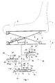
- Fig. 1 is shown in a schematic representation of the basic principle of the pneumatic suspension system based on a vehicle seat.
- the vehicle seat has a backrest 1 and a cushion seat part 2, which is arranged on an upper vehicle seat part 3.
- the vehicle seat part 3 is swingably mounted with respect to a lower vehicle seat part 4 pneumatically suspended and can oscillate up and down, as shown by the double arrow 9.
- the upper vehicle seat part 3 is spaced from the lower vehicle seat part 4.
- An air spring 8 is disposed between the scissor arm 5 and the lower vehicle seat part 4.
- An additional damper 7 is fastened on the one hand to the lower vehicle seat part 4 and on the other hand to the scissor arm 6.
- a first control device 10 serves to supply and discharge air to the air spring 8.
- the first control device 10 consists of a housing 11 with a piston-like element 12 arranged therein, which can be displaced in the longitudinal direction, as represented by the double arrow 13.
- the piston-like element 12 is comprised of two spaced-apart sealing elements 14 and 15 and sealingly mounted relative to the housing.
- Another input and output 18 serves to supply and remove air by means of the line 19 to and from the air spring eighth
- air can be supplied, air can be discharged or a closed system without air supply and discharge can be set. If, for example, the piston-like element 12 is displaced to the right, then air can be discharged from the air spring 8 into the inlet and outlet 18 via the line 19 and escape via the outlet 17. If, however, the piston-like element 12 is displaced to the left, then air 16a can be conducted via the inlet 16 past the sealing element 14 via the inlet and outlet 18 and the line 19 into the air spring 8.
- a second control device 20 essentially has a 2/2 control valve 21, which is arranged within an exhaust air line 22.
- the control valve 21 is deflected by means of the heel in the rack 23 and can thereby either interrupt the exhaust duct 22 or switch to passage.
- a gear is connected as a movement delay member, conventionally known as a honey motor, designated by the reference numeral 26.
- This gear can be moved according to the double arrow 27 to the left and right simultaneously with the displacement of the rack 23 by the teeth of the rack 23, which engage in the teeth of the gear 26, the gear 26 rotate.
- a third control device 30 is constructed similar to the second control device. Again, a control valve in the form of a 2/2-way control valve 31 is provided, which is arranged within a supply air line 32 in order to interrupt or turn on.
- a rack 33 which can be reciprocated along the double arrow 34 and, as well as the rack 23 with the spring 25 can be spring-loaded by the spring 35, as soon as a shift takes place, is arranged.
- the rack 33 in turn cooperates with a gear 36, which is designed as a time delay element and can be rotated along the double arrow 37.
- Both the gear 26 and the gear 36 have a torque of, for example, 10 Ncm, when the gear moves so that the rack 23, 33 is moved back to its original position, ie towards the center of the image.
- the torque counteracts the spring 25, 35, which is stretched by deflection of the rack 23, 33.
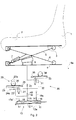
- Fig. 2 is also shown in a schematic representation of the basic principle of the pneumatic suspension system according to the invention according to an embodiment of the invention, this representation represents a state of the control devices and the vehicle seat, which is taken after first reaching a lower Hubendanschlages.
- This illustration shows that the vehicle seat is deflected downwards, as can be seen clearly by the compressed or compressed air spring 8.
- the air spring 8 or another part of the vehicle seat has already reached a Hubendanschlag, whereupon shortly after reaching the Hubendanschlages the second control device 20 is activated. This happens because the rack 23 has been deflected upon reaching the Hubendanschlages and has moved in the direction of arrow 24a. As a result, the control valve 21 is deflected, which has an interruption of the exhaust air line 22 result. This is clearly shown in the illustration.
- the third control device is unchanged so far.
- the piston-like element 12 is now shifted to the left, so that air 16a can flow out of the input and output 18 through the input 16 and flow through the line 19 and the valve 40 and the air supply line 32 in the air spring 8 can.
- the exhaust air line is interrupted and the supply air line 32 is turned on.
- Fig. 3 the basic principle of the pneumatic suspension system according to the invention with associated vehicle seat is shown in a further state after reaching the upper Hubendanschlages. Identical and equivalent parts are provided with the same reference numerals.
- the arrow 34a shows the movement of the rack for the deflection, ie for the movement in a deflection position and the arrow 37a shows the rotational movement of the gear 36, which is associated with the deflection movement of the rack 33.
- the period of time during which the honey-making motor allows the toothed rod 23, 33 to return to its initial position and thus to switch the valves 31, 21 into a switching-through mode is preferably adjustable between 0 and 10 seconds.
- Fig. 4 is shown in a schematic representation of the components of the spring system according to the invention. Identical and equivalent parts are provided with the same reference numerals.
- This illustration clearly shows that the positioning of the first control device 10 preferably takes place between the upper vehicle seat part 3 and the scissor arm 6.
- this illustration shows that the second and third control device 20 and 30 preferably in the form of separate components and subsequently can be arranged, said components z. B. with a roller-like element 6a, which is connected to the scissor arm 6, can interact, in which the roller-like element 6a is rolled to the left or to the right depending on the deflection of the scissor arm and instantaneous height adjustment of the vehicle seat.
- This roller-like element 6a will actuate an actuating element 20a, which interacts with the toothed rack 23, in the case of a predefinable stroke end stop in the second control device 20.
- the roller-like element 6a Upon reaching a lower Hubendanschlages the roller-like element 6a will interact with an actuator 30a of the third control device, which interacts with the rack 33.
- Fig. 5 is a schematic diagram of the waveform of the pneumatic suspension system according to the invention shown upon reaching a lower Hubendanschlages the suspension system.
- a vibration 50 which the pneumatic suspension system performs takes place above and below a normally existing zero line 51.
- a line 52 is reached with an upward deflection of the suspension system, normally takes place the discharge of air from the air spring instead of acting against the oscillatory motion in the direction of the zero line 51.
- a line 53 is exceeded, the supply of air takes place in order to counteract the oscillatory movement in the direction of the zero line 51. This applies to a normally occurring vibration, ie without reaching a Hubendanschlages.
- Such supplying of air instead of discharging air in an upward movement immediately after reaching the lower Hubendanschlages and of course a discharge of air instead of the supply of air in a downward movement is performed during a predetermined period 61.
- first and second Hubend Schemee 62 and 63 are shown.
Landscapes
- Engineering & Computer Science (AREA)
- Aviation & Aerospace Engineering (AREA)
- Transportation (AREA)
- Mechanical Engineering (AREA)
- Vehicle Body Suspensions (AREA)
- Vibration Prevention Devices (AREA)
Abstract
Die Erfindung betrifft ein pneumatisches Federungssystem für Fahrzeuge mit mindestens einem ersten und einem zweiten Teil (3, 4), wobei beide Teile (3, 4) mittels mindestens einer Luftfeder (8) schwingungsbeweglich und pneumatisch federnd zueinander gelagert sind, wobei eine erste Regelungseinrichtung (10) zum Zu- und Abführen von Luft in und aus der Luftfeder (8) angeordnet ist, welche das Abführen von Luft durchführt, nachdem ein erster Hubendbereich (62) des Federungssystems, bei dem sich die Luftfeder (8) in einem gestauchten Zustand befindet, erreicht worden ist, und welche das Zuführen von Luft durchführt, nachdem ein zweiter Hubendbereich (63) des Federungssystems, bei dem sich die Luftfeder (8) in einem auseinandergezogenen Zustand befindet, erreicht worden ist, wobei eine zweite Regelegungseinrichtung (20) zum Zuführen von Luft in die Luftfeder (8) und zum Abschalten des Abführens von Luft aus der Luftfeder (8), während einer vorbestimmbaren ersten Zeitspanne (61), nachdem erstmalig ein erster Hubendanschlag (58) in dem ersten Hubendbereich (62) erreicht worden ist, und/oder eine dritte Regelungseinrichtung (30) zum Abführen von Luft aus der Luftfeder (8) und zum Abschalten des Zuführens von Luft in die Luftfeder (8) während einer vorbestimmbaren zweiten Zeitspanne, nach dem erstmalig ein zweiter Hubendanschlag in dem zweiten Hubendbereich (63) erreicht worden ist.The invention relates to a pneumatic suspension system for vehicles with at least a first and a second part (3, 4), both parts (3, 4) being mounted such that they can move in a vibratory and pneumatic manner relative to one another by means of at least one air spring (8), a first control device ( 10) for supplying and discharging air into and out of the air spring (8), which carries out the removal of air, after a first stroke end region (62) of the suspension system, in which the air spring (8) is in a compressed state has been achieved and which performs the supply of air after a second stroke end region (63) of the suspension system, in which the air spring (8) is in an expanded state, has been reached, wherein a second control device (20) for supplying air into the air spring (8) and for switching off the removal of air from the air spring (8), during a predeterminable first period (61) after a first stroke end stop (58) in the first stroke end area (62) has been reached, and or a third control device (30) for discharging air from the air spring (8) and for switching off the supply of air into the air spring (8) during a predeterminable second period of time after a second stroke end stop has been reached in the second stroke end region (63) for the first time is.
Description
Die Erfindung betrifft ein pneumatisches Federungssystem für Fahrzeuge mit mindestens einem ersten und einem zweiten Teil, wobei beide Teile mittels mindestens einer Luftfeder schwingungsbeweglich und pneumatisch federnd zueinander gelagert sind, gemäß dem Oberbegriff des Patentanspruches 1 und ein Verfahren zum pneumatischen Federn von Fahrzeugteilen gemäß dem Oberbegriff des Patentanspruches 10.The invention relates to a pneumatic suspension system for vehicles with at least a first and a second part, wherein both parts are mounted by means of at least one air spring vibrationally movable and pneumatically resilient to each other, according to the preamble of
Pneumatische Federungssysteme für Fahrzeuge sowie Verfahren zum pneumatischen Federn von Fahrzeugteilen sind aus verschiedenen Bereichen eines Fahrzeuges bekannt. Pneumatische Federungssysteme werden insbesondere bei pneumatisch gefederten Fahrzeugsitzen, pneumatisch gefederten Fahrzeugkabinen und pneumatisch gefederten Fahrwerken von Fahrzeugen eingesetzt.Pneumatic suspension systems for vehicles as well as methods for the pneumatic springing of vehicle parts are known from various areas of a vehicle. Pneumatic suspension systems are used in particular in pneumatically sprung vehicle seats, pneumatically sprung vehicle cabins and pneumatically sprung chassis of vehicles.
Insbesondere bei pneumatisch gefederten Fahrzeugsitzen ergibt sich häufig das Problem, dass konstruktionsbedingt und aufgrund des begrenzt zur Verfügung stehenden Einbauraumes innerhalb von Fahrzeugen nur begrenzt Restfederwege von Luftfedern, die zur federnden Lagerung zwischen Fahrzeugsitzoberteilen und Fahrzeugsitzunterteilen eingebaut werden, zur Verfügung stehen. Dies trifft insbesondere dann zu, wenn vorab eine etwas niedrigere Sitzposition des Fahrzeugsitzes eingestellt wird, da sich beispielsweise eine kleinere Person auf dem Sitz befindet, die ebenso als Fahrer mit ihren Füßen einen ständigen Kontakt zu den Brems- und Gaspedalen des Fahrzeuges haben muss. In diesem Fall ist beim Befahren eines sehr unebenen Fahrweges die Gefahr groß, dass bei einer Einleitung einer Schwingung von unten, also bei einem Überfahren einer Erhebung auf der Fahrbahn, die Luftfeder derart stark gestaucht bzw. komprimiert wird, dass sie an ihren Hubendanschlag gelangt, wobei dieses Erreichen des Hubendanschlages nicht nur für eine Luftfeder zutreffen kann, sondern für jedes weitere schwingungsbewegliche Element innerhalb des Fahrzeugsitzes, welches ebenso in eine Hubendlage, beispielsweise aufgrund des begrenzten Bauraums, gelangen kann.Especially with pneumatically sprung vehicle seats often results in the problem that due to the design and due to the limited available installation space within vehicles only limited residual spring travel of air springs, which are installed for resilient mounting between the vehicle seat tops and vehicle seat bases are available. This is particularly true when a slightly lower seating position of the vehicle seat is set in advance, for example, because a smaller person is on the seat, as well as the driver with their feet must have a permanent contact with the brake and accelerator pedals of the vehicle. In this case, the Driving a very uneven roadway, the danger that when an initiation of a vibration from below, so when driving over a survey on the road, the air spring is so strong compressed or compressed that it reaches its Hubendanschlag, this reaching the Hubendanschlages can not apply only to an air spring, but for each additional vibrationally movable element within the vehicle seat, which can also go into a stroke end position, for example due to the limited space.
Das Einstellen einer relativ stabilen Niveaulage des Fahrzeugsitzes wird in der Regel bei derartigen luftgefederten Fahrzeugsitzen mittels einer so genannten offenen Steuerung geregelt. Dies bedeutet, dass mittels einer Steuerung bei Einleitung einer Schwingung in das Federungssystem entweder Druckluft in das Federungssystem und damit in die Luftfeder zugeführt oder aus diesem/dieser abgeführt wird. Beispielsweise wird bei einem starken Zusammendrücken der Luftfeder aufgrund einer starken Einleitung einer Schwingungsbewegung beim Überfahren einer Fahrbahnerhebung Luft zugeführt, wohingegen bei einem Auseinanderziehen der Luftfeder während einer starken Einleitung einer Schwingung aufgrund des Durchfahrens einer Mulde in der Fahrbahn Luft aus der Luftfeder abgeführt wird.The setting of a relatively stable level position of the vehicle seat is usually controlled in such air-suspension vehicle seats by means of a so-called open control. This means that either compressed air is supplied into the suspension system and thus into the air spring or discharged from this / this by means of a control upon initiation of a vibration in the suspension system. For example, in a strong compression of the air spring due to a strong initiation of a vibrational movement when driving over a driving surface elevation air is supplied, whereas when a pulling apart of the air spring during a strong initiation of vibration due to the passage of a trough in the roadway air is removed from the air spring.
Wenn nun im Federungssystem und damit der Luftfeder bei der Einleitung starker Schwingungsbewegungen ein nur geringer Federweg zum Ausgleich der Schwingungsbewegung zur Verfügung steht, besteht die Gefahr des Berührens des Hubendanschlags, welches für den Fahrer sehr schmerzhaft sein kann. Als Gegenmaßnahme werden häufig zusätzlich angeordnete hydraulische Dämpfer derart verstellt, dass sie eine harte Dämpfung aufweisen, um der Schwingungsbewegung entgegenzuwirken. Dies hat zur Folge, dass zwar die Hubendanschläge bzw. Hubendlagen nicht erreicht werden, jedoch auch eine schwache Abdämpfung der eingeleiteten Schwingungsbewegungen in dem Federungssystem und damit in dem Fahrzeugsitz für den Fahrer spürbar erfolgt.If now in the suspension system and thus the air spring at the initiation of strong vibration movements only a small spring travel to compensate for the vibration movement is available, there is a danger of touching the Hubendanschlags, which can be very painful for the driver. As a countermeasure, additionally arranged hydraulic dampers are often adjusted in such a way that they have a hard damping in order to counteract the oscillatory movement. This has the consequence that although the Hubendanschläge or Hubendlagen not be achieved, but also a slight attenuation of the introduced oscillatory movements in the suspension system and thus in the vehicle seat for the driver is noticeable.
Eine weitere bekannte entgegenwirkende Maßnahme ist die Verstellung des Fahrzeugsitzes in seiner Höhe, so dass das Federungssystem wieder in einer mittleren Position bezüglich des zur Verfügung stehenden Federweges angeordnet ist. Dies kann jedoch wiederum zur Folge haben, dass der Fahrer, wenn es sich um eine kleine Person handelt, nicht mehr das Fahrzeug zuverlässig bedienen kann, da Bremspedale, Kupplungspedale und dergleichen nicht mehr zuverlässig mit dem Fuß erreicht werden können.Another known counteracting measure is the adjustment of the vehicle seat in its height, so that the suspension system is again arranged in a middle position with respect to the available spring travel. However, this can in turn mean that the driver, if it is a small person, can no longer reliably operate the vehicle, since brake pedals, clutch pedals and the like can no longer be reliably reached with the foot.
Demzufolge liegt der vorliegenden Erfindung die Aufgabe zugrunde, ein pneumatisches Federungssystem für Fahrzeuge und ein Verfahren zum pneumatischen Federn von Fahrzeugteilen zur Verfügung zu stellen, bei dem trotz eines begrenzt zur Verfügung stehenden Restfederweges des Federungssystems und insbesondere einer zur pneumatischen Federung verwendeten Luftfeder eine in dem Fahrzeug sitzende Person einen hohen Sitzkomfort erfährt.Accordingly, the present invention seeks to provide a pneumatic suspension system for vehicles and a method for pneumatic springs of vehicle parts available, in spite of a limited available Restfederweges the suspension system and in particular a pneumatic spring used for air suspension in the vehicle seated person experiences a high level of comfort.
Diese Aufgabe wird vorrichtungsseitig durch die Merkmale des Patentanspruches 1 und verfahrensseitig durch die Merkmale des Patentanspruches 10 gelöst.This object is achieved by the device side by the features of
Ein wesentlicher Punkt der Erfindung liegt darin, dass bei einem pneumatischen Federungssystem für Fahrzeuge mit mindestens einem ersten und einem zweiten Teil, wobei beide Teile mittels mindestens einer Luftfeder schwingungsbeweglich und pneumatisch federnd zueinander gelagert sind und eine erste Regelungseinrichtung zum Zu- und Abführen von Luft in und aus der Luftfeder angeordnet ist, welche das Abführen von Luft durchführt, nachdem ein erster Hubendbereich des Federungssystems, bei dem sich die Luftfeder in einem gestauchten Zustand befindet, erreicht worden ist, und welche das Zuführen von Luft durchführt, nachdem ein zweiter Hubendbereich des Federungssystems, bei dem sich die Luftfeder in einem auseinandergezogenen Zustand befindet, erreicht worden ist, eine zweite Regelungseinrichtung zum Zuführen von Luft in die Luftfeder und zum Abschalten des Abführens von Luft in der Luftfeder während einer vorbestimmbaren ersten Zeitspanne angeordnet ist, nachdem erstmalig ein erster Hubendanschlag in dem ersten Hubendbereich erreicht worden ist. Zusätzlich oder alternativ kann eine dritte Regelungseinrichtung zum Abführen von Luft aus der Luftfeder und zum Abschalten des Zuführens von Luft in die Luftfeder während einer vorbestimmbaren zweiten Zeitspanne, nachdem erstmalig ein zweiter Hubendanschlag in dem zweiten Hubendbereich erreicht worden ist, angeordnet sein.An essential point of the invention is that in a pneumatic suspension system for vehicles with at least a first and a second part, wherein both parts are mounted by means of at least one air spring vibrationally movable and pneumatically resilient to each other and a first control device for supplying and discharging air in and disposed from the air spring, which performs the discharge of air after a first Hubendbereich the suspension system, in which the air spring is in a compressed state, has been reached, and which performs the supply of air, after a second Hubendbereich the suspension system in which the air spring is in an exploded state has been reached, a second control means for supplying air into the air spring and for switching off the discharge of air in the air spring for a predeterminable first period of time is arranged after a first ers ter Hubendanschlag has been achieved in the first Hubendbereich. Additionally or alternatively, a third control means for removing air from the air spring and for switching off the supply of air in the air spring for a predeterminable second period of time after a first Hubendanschlag in the second Hubendbereich has been achieved for the first time be arranged.
Mittels eines derartigen pneumatischen Federungssystems ist es erstmalig möglich, temporär, also für eine vorbestimmbare Zeitspanne, vorzugsweise für die Gesamtdauer von starken Einleitungen von Schwingungsbewegungen in das Federungssystem, die zur Verfügung stehenden Restfederwege bei Erreichen von Hubendanschlägen anzupassen. Denn eine derartige dynamische Federweganpassung für pneumatische Federungssysteme führt in einem Zustand der Luftfeder, in dem bisher das Abführen von Luft aus der Luftfeder zur Vermeidung eines Hubendanschlages der sich auseinanderbewegenden Luftfeder durchgeführt worden ist, die zweite Regelungseinrichtung, die separat oder integriert in der ersten Regelungseinrichtung ebenso wie die dritte Regelungseinrichtung angeordnet sein kann, Luft in die Luftfeder, wobei zugleich das bisher übliche Abführen von Luft aus der Luftfeder abgeschaltet wird. Dies geschieht lediglich während eines vorbestimmbaren Zeitraumes, also während der vorbestimmbaren ersten Zeitspanne, nachdem erstmalig der erste Hubendanschlag erreicht worden ist, um begrenzt auf diese erste Zeitspanne, während welcher die Einleitung von starken Schwingungsbewegungen stattfinden, eine Abdämpfung der Schwingungsbewegung des Federungssystems, in diesem Fall bei einer sich auseinanderbewegenden Luftfeder, zu erhalten. Dies trifft bei Fahrzeugsitzen dann zu, wenn der Fahrzeugsitz sich nach oben bewegt, also das Fahrzeugsitzoberteil sich gegenüber dem Fahrzeugsitzunterteil von diesem entfernt. Sobald diese Einleitung einer starken Schwingungsbewegung nachlässt und die vorbestimmbare Zeitspanne abgelaufen ist, findet wieder eine Rückkehr in den normalen Luftabführmodus statt und ein Zuführen der Luft in die Luftfeder wird während einer Nachobenbewegung des Fahrzeugsitzes nicht mehr durchgeführt.By means of such a pneumatic suspension system, it is possible for the first time, temporarily, so for a predeterminable period of time, preferably for the total duration of strong discharges of oscillatory movements in the suspension system to adjust the available residual spring travel when reaching Hubendanschlägen. Because such a dynamic suspension travel adjustment for pneumatic suspension systems leads in a state of the air spring, in the hitherto the removal of air from the air spring Avoiding Hubendanschlages of the moving apart spring has been performed, the second control device, which may be arranged separately or integrated in the first control device as well as the third control device, air in the air spring, at the same time the usual discharge of air from the air spring is turned off , This happens only during a predeterminable time period, that is to say during the predeterminable first period of time after the first stroke end stop has been reached, in order to limit this first time span during which strong oscillatory movements are initiated, damping the oscillation movement of the suspension system, in this case in a diverging air spring to obtain. This applies in the case of vehicle seats when the vehicle seat is moving upwards, that is to say the vehicle seat upper part is remote from the vehicle seat lower part. As soon as this initiation of a strong oscillating movement subsides and the predeterminable period of time has expired, a return to the normal air discharge mode takes place again and an introduction of the air into the air spring is no longer carried out during an upward movement of the vehicle seat.
Anders herum wird mittels der dritten Regelungseinrichtung bei einem Erreichen eines oberseitigen Hubendanschlages der Luftfeder anschließend Luft entnommen, anstatt Luft zuzuführen, wie es bei einem normalen Schwingungsverlauf ohne Einleitung starker Schwingungen der Fall wäre. Dies findet so lange statt, bis die vorbestimmbare zweite Zeitspanne abgelaufen ist. Während dieser zweiten Zeitspanne, also während der Einleitung starker Schwingungen für eine nach unten gerichtete Bewegung des Fahrzeugsitzes, die sich nach Erreichen des oberseitigen Hubendanschlages einstellt, und dann durchgeführt wird, wenn bei Erreichen des oberen Hubendanschlages eine Schwingung aufgrund des Durchfahrens einer stark ausgeprägten Mulde in der Fahrbahn eingeleitet wird, wird also entgegen den bisherigen Normalmodus nicht Luft zugeführt, wie es bei der Einleitung schwächerer Schwingungsbewegungen der Fall wäre, sondern es wird durch die dritte Regelungseinrichtung die Luft abgeführt, unmittelbar nachdem der Endanschlag erreicht worden ist. Dieses Abführen von Luft mittels der dritten Regelungseinrichtung während einer nach unten gerichteten Bewegung des Fahrzeugsitzes wird abwechselnd mit dem Zuführen von Luft durch die zweite Regelungseinrichtung während einer nach oben gerichteten Bewegung des Fahrzeugsitzes so lange durchgeführt, bis die jeweiligen ersten und zweiten Zeitspannen abgelaufen sind, deren Dauer sich danach richtet, wie lange die Einleitung der starken Schwingungsbewegungen stattfindet.On the other hand, air is then taken from the air spring by means of the third control device when reaching a top-side Hubendanschlages of the air spring, instead of supplying air, as would be the case with a normal waveform without the introduction of strong vibrations. This takes place until the predeterminable second time period has expired. During this second period, ie during the initiation of strong vibrations for a downward movement of the vehicle seat, which occurs after reaching the top Hubendanschlages, and then carried out when reaching the upper Hubendanschlages an oscillation due to the passage of a pronounced trough in the lane is initiated, so is not supplied contrary to the previous normal mode air, as would be the case with the introduction of weaker vibration movements, but it is discharged through the third control device, the air immediately after the end stop has been reached. This discharge of air by means of the third control means during a downward movement of the vehicle seat is performed alternately with the supply of air by the second control means during an upward movement of the vehicle seat until the respective first and second time periods have elapsed Duration depends on how long the initiation of the strong vibration movements takes place.
Vorzugsweise wird das Abschalten des Abführens von Luft während des Zuführens von Luft durch die zweite Regelungseinrichtung und die erste Regelungseinrichtung ebenso wie das Abschalten des Zuführens von Luft durch die erste Regelungseinrichtung während des Abführens von Luft durch die dritte Regelungseinrichtung und durch die erste Regelungseinrichtung von der Schwingungsfrequenz der schwingend zueinander beweglichen Teile gesteuert. Das heißt, sobald beispielsweise eine Schwingungsfrequenz des Federungssystems und damit der schwingend zueinander beweglichen Teile von mehr als 0,5 Hz auftritt, findet eine Abschaltung des Abführens der Luft nach Erreichen des unteren Hubendanschlages des Fahrzeugsitzes statt. Nach Erreichen des oberen Hubendanschlages hingegen wird ebenso ab einer bestimmten Schwingungsfrequenz von beispielsweise 0,5 Hz das Zuführen der Luft abgeschaltet. Die Folge daraus ist, dass sich nach Erreichen der Hubendanschläge die Restfederwege erhöhen und zwar so lange, bis keine Hubanschläge mehr berührt werden. Hieraus ergibt sich der für eine optimale Schwingungsbewegung des Federungssystems unter bestmöglicher Vermeidung des Erreichens der Hubendanschläge erforderliche Restfederweg.Preferably, the shut-off of the discharge of air during the supply of air by the second control means and the first control means as well as the shut-off of the supply of air by the first control means during the discharge of air by the third control means and by the first control means of the oscillation frequency the oscillating moving parts controlled. That is, as soon as, for example, an oscillation frequency of the suspension system and thus the swingingly mutually moving parts of more than 0.5 Hz occurs, a shutdown of the discharge of the air takes place after reaching the lower Hubendanschlages the vehicle seat. After reaching the upper Hubendanschlages, however, the supply of air is switched off just above a certain oscillation frequency of, for example, 0.5 Hz. The consequence of this is that after reaching the Hubendanschlägen the residual spring travel increase and that until such time as no more stroke stops are touched. This results in the necessary for optimal vibration movement of the suspension system with the best possible avoidance of reaching the Hubendanschläge residual spring travel.
Nach Erreichen des oberen Hubendanschlages des Fahrzeugsitzes, also einem Sichnachobenbewegen des Fahrzeugsitzes wird nicht, wie bei Erreichen des unteren Hubendanschlages, das Abführen der Luft abgeschaltet, sondern das Zuführen der Luft.After reaching the upper Hubendanschlages the vehicle seat, so a Sichnachobenbewegen the vehicle seat is not, as when reaching the lower Hubendanschlages, the discharge of the air off, but the supply of air.
Selbstverständlich können die zweite oder dritte Regelungseinrichtung auch alleine, also ohne die dritte bzw. die zweite Regelungseinrichtung verwendet werden. Dies hat zur Folge, dass eine Restfederwegoptimierung lediglich nach Erreichen eines unteren Hubendanschlages oder nach Erreichen eines oberen Hubendanschlages erhalten wird.Of course, the second or third control device can also be used alone, ie without the third or the second control device. This has the consequence that a Restfederwegoptimierung is obtained only after reaching a lower Hubendanschlages or after reaching an upper Hubendanschlages.
Das Zurücksetzen in den normalen Schwingungsregelungsvorgang, in dem lediglich die erste Regelungseinrichtung, jedoch nicht direkt die zweite und dritte Regelungseinrichtung aktiv sind, kann wiederum von der Schwingungsfrequenz der schwingungsbeweglichen Teile abhängig gemacht werden. Vorzugsweise wird eine derartige Rücksetzfrequenz bei weniger als 0,8 Hz durchgeführt.The resetting to the normal vibration control process, in which only the first control means, but not directly the second and third control means are active, can in turn be made dependent on the vibration frequency of the vibration-movable parts. Preferably, such a reset frequency is performed at less than 0.8 Hz.
Gemäß einer bevorzugten Ausführungsform weist die zweite Regelungseinrichtung ein erstes Regelventil auf, vorzugsweise ein 2/2-Wege-Ventil, welches in einer Abluftleitung, die die Luftfeder mit der ersten Regelungseinrichtung verbindet, zum Ein- und Abschalten des Abführens von Luft aus der Luftfeder angeordnet ist. Ebenso kann die dritte Regelungseinrichtung ein zweites Regelventil, vorzugsweise ein 2/2-Wege-Ventil aufweisen, welches in einer Zuluftleitung, die die Luftfeder mit der ersten Regelungseinrichtung verbindet, zum Ein- und Abschalten des Zuführens von Luft in die Luftfeder angeordnet ist.According to a preferred embodiment, the second control device to a first control valve, preferably a 2/2-way valve, which in an exhaust duct, the Air spring connects to the first control device, is arranged to turn on and off the discharge of air from the air spring. Likewise, the third control device may comprise a second control valve, preferably a 2/2-way valve, which is arranged in an air supply line which connects the air spring with the first control device for switching on and off of the supply of air in the air spring.
Gemäß einer bevorzugten Ausführungsform sind das zweite und das dritte Regelventil jeweils mittels mindestens einem beweglichen Element, das durch eines der schwingungsbeweglichen Elemente bewegbar ist, schaltbar.According to a preferred embodiment, the second and the third control valve in each case by means of at least one movable element, which is movable by one of the vibration-movable elements, switchable.
Jedes bewegliche Element ist mit einem Bewegungsverzögerungsglied verbunden, um während der ersten bzw. zweiten Zeitspanne das bewegliche Element entgegen einer Federbeaufschlagungskraft verzögert in eine Ausgangsposition zurückzubewegen.Each movable member is connected to a motion delay member for retarding the movable member against a spring loading force to a home position during the first and second time periods, respectively.
Gemäß einer Weiterbildung der Erfindung ist das bewegliche Element als Zahnstange ausgebildet und das Bewegungsverzögerungsglied als drehbares Zahnrad ausgebildet, welches mit der Zahnstange zusammenwirkt und mit einem vorbestimmbaren Drehmoment beaufschlagbar ist, wobei das Drehmoment von beispielsweise 10 Ncm nur in eine erste Drehrichtung des Zahnrades, bei der sich die Zahnstange von einer Auslenkposition in die Ausgangsposition bewegt, wirkt. Wird hingegen die Zahnstange von der Ausgangsposition in die Auslenkposition bewegt, wird ein Drehmoment von 0 Ncm angesetzt, so dass der Beginn der ersten und der zweiten Zeitspanne durch Bewegen bzw. Verschieben der Zahnstange und dem zeitgleichen Schalten bzw. Betätigen des ersten und/oder zweiten Regelventils unmittelbar nach Betätigen durch ein schwingungsbewegliches Teil, welches sich kurz vor dem Hubendanschlag des Federungssystems befindet, erfolgt.According to one embodiment of the invention, the movable member is formed as a rack and the movement delay member is formed as a rotatable gear, which cooperates with the rack and can be acted upon by a predeterminable torque, wherein the torque of, for example, 10 Ncm only in a first rotational direction of the gear in the the rack moves from a deflection position to the starting position, acts. On the other hand, when the rack is moved from the home position to the deflected position, a torque of 0 Ncm is set so that the start of the first and second periods by moving the rack and simultaneously switching the first and / or second Control valve immediately after actuation by a vibration movable part, which is located shortly before the Hubendanschlag the suspension system takes place.
Gemäß einer bevorzugten Ausführungsform führt eine Schwingungsfrequenzschalteinrichtung ab einer vorbestimmbaren Schwingungsfrequenz der schwingungsbeweglichen Teile das Abschalten des Abführens von Luft aus der Luftfeder zu Beginn der ersten Zeitspanne und das Abschalten des Zuführens von Luft in die Luftfeder zu Beginn der zweiten Zeitspanne durch.According to a preferred embodiment, an oscillation frequency switching means from a predeterminable oscillation frequency of the oscillatory moving parts performs the switching off of the discharge of air from the air spring at the beginning of the first period and the switching off of the supply of air in the air spring at the beginning of the second period.
Das erfindungsgemäße Federungssystem sowie das erfindungsgemäße Verfahren können beispielsweise auf Fahrzeugsitze angewendet werden, wobei das erste Teil ein Fahrzeugsitzoberteil und das zweite Teil ein Fahrzeugsitzunterteil ist. Alternativ kann es für Fahrzeugkabinen angewendet werden, wobei das erste Teil die Fahrzeugkabine an sich und das zweite Teil beispielsweise das Fahrzeuggrundgestell ist. Ebenso kann es auf Fahrwerke von Fahrzeugen angewendet werden, wobei der Fahrzeugrahmen das erste Teil und die Radaufhängung das zweite Teil darstellt.The suspension system according to the invention and the method according to the invention can be applied, for example, to vehicle seats, wherein the first part is a vehicle seat upper part and the second part is a vehicle seat bottom. Alternatively, it may be applied to vehicle cabins, the first part being the vehicle cab itself and the second part being, for example, the vehicle chassis. Likewise, it can be applied to chassis of vehicles, wherein the vehicle frame is the first part and the suspension is the second part.
Es wird ebenso gezeigt ein Verfahren zum pneumatischen Federn von Fahrzeugteilen mit mindestens einem ersten und einem zweiten Teil, wobei beide Teile mittels mindestens einer Luftfeder sich schwingend zueinander bewegen und pneumatisch federnd zueinander gelagert sind, wobei eine erste Regelungseinrichtung Luft in und aus der Luftfeder zu und abführt, welche das Abführen von Luft durchführt, nachdem ein erster Hubendbereich des Federungssystems, bei dem sich die Luftfeder in einem gestauchten Zustand befindet, erreicht worden ist, und welche das Zuführen von Luft durchführt, nachdem ein zweiter Hubendbereich des Federungssystems, bei dem sich die Luftfeder in einem auseinandergezogenenen Zustand befindet, erreicht worden ist,
wobei mittels einer zweiten Regelungseinrichtung Luft in die Luftfeder zugeführt wird und das Abführen von Luft aus der Luftfeder während einer vorbestimmbaren ersten Zeitspanne abgeschaltet wird, nachdem erstmalig ein erster Hubendanschlag in dem ersten Hubendbereich erreicht worden ist,
und/oder mittels einer dritten Regelungseinrichtung während einer vorbestimmbaren zweiten Zeitspanne Luft aus der Luftfeder abgeführt wird und das Zuführen von Luft in die Luftfeder abgeschaltet wird, nachdem erstmalig ein zweiter Hubendanschlag in dem zweiten Hubendbereich erreicht worden ist.It is also shown a method for pneumatic springs of vehicle parts having at least a first and a second part, wherein both parts by means of at least one air spring to move oscillating to each other and are mounted pneumatically resilient to each other, wherein a first control means in and out of the air spring and discharging air which performs after a first Hubendbereich the suspension system in which the air spring is in a compressed state, has been reached, and which performs the supply of air, after a second Hubendbereich the suspension system in which the Air spring is located in an exploded state, has been achieved
wherein air is supplied into the air spring by means of a second control device and the removal of air from the air spring is switched off during a predeterminable first period of time after a first stroke end stop has first been reached in the first stroke end region,
and / or by means of a third control device for a predeterminable second time period air is discharged from the air spring and the supply of air is switched off in the air spring after a second Hubendanschlag has been achieved in the second Hubendbereich first time.
Weitere vorteilhafte Ausführungsformen ergeben sich aus den Unteransprüchen und der nachfolgenden Beschreibung in Verbindung mit der Zeichnung, wobei diese zeigen:
- Fig. 1
- in einer schematischen Darstellung grundsätzlich die Funktion des erfindungsgemäßen pneumatischen Federungssystems gemäß einer Ausführungsform der Erfindung während einer normalen Schwingungsbewegung ohne Erreichen eines Hubendanschlages;
- Fig. 2
- in einer schematischen Darstellung das pneumatische Federungssystem gemäß der Ausführungsform nach Erreichen eines unteren Hubendanschlages;
- Fig. 3
- in einer schematischen Darstellung das erfindungsgemäße pneumatische Federungssystem gemäß der Ausführungsform der Erfindung nach Erreichen des oberen Hubendanschlages;
- Fig. 4
- in einer schematischen Darstellung einen Fahrzeugsitz mit dem pneumatischen Federungssystem gemäß einer Ausführungsform der Erfindung; und
- Fig. 5
- in einem Diagramm den Verlauf einer Schwingungsbewegung gemäß dem erfindungsgemäßen Verfahren, wie es durch das pneumatische Federungssystem durchgeführt werden kann, nach Erreichen eines unteren Hubendanschlages.
- Fig. 1
- in a schematic representation, in principle, the function of the pneumatic suspension system according to the invention according to an embodiment of the invention during a normal oscillation movement without reaching a Hubendanschlages;
- Fig. 2
- in a schematic representation of the pneumatic suspension system according to the embodiment after reaching a lower Hubendanschlages;
- Fig. 3
- in a schematic representation of the pneumatic suspension system according to the invention according to the embodiment of the invention after reaching the upper Hubendanschlages;
- Fig. 4
- in a schematic representation of a vehicle seat with the pneumatic suspension system according to an embodiment of the invention; and
- Fig. 5
- in a diagram, the course of a vibrational movement according to the inventive method, as it can be performed by the pneumatic suspension system, after reaching a lower Hubendanschlages.
In
Mittels eines Scherengestelles mit den Scherenarmen 5, 6 ist das obere Fahrzeugsitzteil 3 gegenüber dem unteren Fahrzeugsitzteil 4 beabstandet. Eine Luftfeder 8 ist zwischen dem Scherenarm 5 und dem unteren Fahrzeugsitzteil 4 angeordnet. Ein zusätzlicher Dämpfer 7 ist einerseits am unteren Fahrzeugsitzteil 4 und andererseits am Scherenarm 6 befestigt.By means of a scissors rack with the
Eine erste Regelungseinrichtung 10 dient dazu, der Luftfeder 8 Luft zuzuführen und abzuführen. Die erste Regelungseinrichtung 10 besteht aus einem Gehäuse 11 mit einem darin angeordneten kolbenartigen Element 12, welches sich in Längsrichtung verschieben lässt, wie es durch den Doppelpfeil 13 dargestellt wird.A
Das kolbenartige Element 12 ist von zwei voneinander beabstandeten Abdichtungselementen 14 und 15 umfasst und gegenüber dem Gehäuse abdichtend gelagert.The piston-
An einer Eingangsöffnung 16 wird Luft 16a zugeführt und an einem Ausgang 17 wird Luft 17a abgeführt.At an
Ein weiterer Ein- und Ausgang 18 dient zum Zu- und Abführen von Luft mittels der Leitung 19 zu und von der Luftfeder 8.Another input and
Je nachdem, wo das kolbenartige Element 12 gerade angeordnet ist, kann entweder Luft zugeführt werden, Luft abgeführt werden oder ein geschlossenes System ohne Luftzu- und Abführung eingestellt werden. Wird beispielsweise das kolbenartige Element 12 nach rechts verschoben, so kann über die Leitung 19 Luft aus der Luftfeder 8 in den Ein- und Ausgang 18 abgeleitet werden und über den Ausgang 17 entweichen. Wird hingegen das kolbenartige Element 12 nach links verschoben, so kann Luft 16a über den Eingang 16 an dem Abdichtungselement 14 vorbei über den Ein- und Ausgang 18 und die Leitung 19 in die Luftfeder 8 geleitet werden.Depending on where the piston-
Eine zweite Regelungseinrichtung 20 weist im Wesentlichen ein 2/2-Regelventil 21 auf, welches innerhalb einer Abluftleitung 22 angeordnet ist. Durch Bewegen bzw. Verschieben einer Zahnstange 23, wie es durch den Doppelpfeil 24 gezeigt wird, wird das Regelventil 21 mittels des Absatzes in der Zahnstange 23 ausgelenkt und kann hierdurch die Abluftleitung 22 entweder unterbrechen oder auf Durchlass schalten.A
Zusammenwirkend mit der Zahnstange 23 ist ein Zahnrad als Bewegungsverzögerungsglied, herkömmlicherweise als Honigmotor bekannt, mit dem Bezugszeichen 26 bezeichnet, verbunden. Dieses Zahnrad kann gemäß dem Doppelpfeil 27 nach links und rechts zeitgleich mit dem Verschieben der Zahnstange 23 bewegt werden, indem die Zähne der Zahnstange 23, welche in die Zähne des Zahnrades 26 eingreifen, das Zahnrad 26 verdrehen.Cooperating with the
Ebenso ist eine dritte Regelungseinrichtung 30 ähnlich zu der zweiten Regelungseinrichtung aufgebaut. Wiederum ist ein Regelventil in Form eines 2/2-Regelventils 31 vorhanden, welches innerhalb einer Zuluftleitung 32 angeordnet ist, um diese zu unterbrechen oder durchzuschalten.Likewise, a
Auch eine Zahnstange 33, die entlang des Doppelpfeils 34 hin- und herverschoben werden kann und, ebenso wie die Zahnstange 23 mit der Feder 25, durch die Feder 35 federbeaufschlagt werden kann, sobald eine Verschiebung stattfindet, ist angeordnet. Die Zahnstange 33 wirkt wiederum mit einem Zahnrad 36 zusammen, welches als Zeitverzögerungsglied ausgebildet ist und entlang des Doppelpfeils 37 verdreht werden kann.Also, a
Sowohl das Zahnrad 26 als auch das Zahnrad 36 weisen ein Drehmoment von beispielsweise 10 Ncm auf, wenn das Zahnrad sich derart bewegt, dass die Zahnstange 23, 33 zurück in ihre Ausgangslage, also in Richtung Bildmitte, verschoben wird. Dem Drehmoment entgegen wirkt die Feder 25, 35, die durch Auslenkung der Zahnstange 23, 33 gespannt wird.Both the
In
Gleiche und gleichbedeutende Teile sind mit gleichem Bezugszeichen versehen.Identical and equivalent parts are provided with the same reference numerals.
Dieser Darstellung ist zu entnehmen, dass der Fahrzeugsitz nach unten ausgelenkt ist, wie es durch die gestauchte bzw. zusammengedrückte Luftfeder 8 deutlich zu erkennen ist. Die Luftfeder 8 oder ein anderes Teil des Fahrzeugsitzes hat bereits einen Hubendanschlag erreicht, woraufhin kurz nach Erreichen des Hubendanschlages die zweite Regelungseinrichtung 20 aktiviert wird. Dies geschieht dadurch, dass die Zahnstange 23 bei Erreichen des Hubendanschlages ausgelenkt worden ist und sich in Richtung des Pfeils 24a bewegt hat. Hierdurch wird das Regelventil 21 ausgelenkt, welches eine Unterbrechung der Abluftleitung 22 zur Folge hat. Dies ist deutlich der Darstellung zu entnehmen.This illustration shows that the vehicle seat is deflected downwards, as can be seen clearly by the compressed or compressed
Zugleich wird die Feder 25 aufgrund der Verschiebung der Zahnstange 23 gespannt.At the same time, the
Ebenso hat sich das Zahnrad 26 um seine Achse gedreht, und zwar in Richtung des Pfeils 27a.Similarly, the
Die dritte Regelungseinrichtung hingegen ist bisher unverändert.The third control device, however, is unchanged so far.
In der ersten Regelungseinrichtung 10 ist nun das kolbenartige Element 12 nach links verschoben, so dass Luft 16a durch den Eingang 16 aus dem Ein- und Ausgang 18 ausströmen kann und über die Leitung 19 und das Ventil 40 sowie die Zuluftleitung 32 in die Luftfeder 8 einströmen kann. Somit ist in diesem Zustand - wie beabsichtigt - die Abluftleitung unterbrochen und die Zuluftleitung 32 durchgeschaltet.In the
In
Dieser Darstellung ist zu entnehmen, dass nun die dritte Regelungseinrichtung 30 aktiviert worden ist, wohingegen die zweite Regelungseinrichtung 20 inaktiv ist, in dem die Zahnstange 23 nicht ausgelenkt ist. Die Zahnstange 33 hingegen ist entgegen der Spannkraft der Feder 35 ausgelenkt. Hierdurch ist das Regelventil 31 geschaltet worden und unterbricht somit die Luftzufuhrleitung 32, wie es der Darstellung deutlich zu entnehmen ist.This illustration shows that now the
Der Pfeil 34a zeigt die Bewegung der Zahnstange für die Auslenkung, also für die Bewegung in eine Auslenkposition und der Pfeil 37a zeigt die Drehbewegung des Zahnrades 36, welche mit der Auslenkbewegung der Zahnstange 33 einhergeht.The
Gleichzeitig ist in der ersten Regelungseinrichtung 10 das kolbenartige Element 12 nach rechts verschoben, wie es durch den Pfeil 13b dargestellt wird. Hierdurch kann Luft 17a über den Ausgang 17, den Ein- und Ausgang 18 und die Leitung 19 sowie die Abluftleitung 22 und das Rückschlagventil 41 entweichen.At the same time, the piston-
Nach einer derartigen Auslenkung der Zahnstange 33 in
Die Zeitspanne, innerhalb welcher der Honigmotor das Zurückkehren der Zahnstange 23, 33 in ihre Ausgangsposition und somit das Umschalten der Ventile 31, 21 in einen Durchschaltmodus zulässt, ist vorzugsweise zwischen 0 und 10 Sekunden einstellbar.The period of time during which the honey-making motor allows the
In
Dieser Darstellung ist deutlich zu entnehmen, dass die Positionierung der ersten Regelungseinrichtung 10 vorzugsweise zwischen oberen Fahrzeugsitzteil 3 und dem Scherenarm 6 geschieht. Ebenso ist dieser Darstellung zu entnehmen, dass die zweite und dritte Regelungseinrichtung 20 und 30 vorzugsweise in Form von separaten Bauteilen auch nachträglich anordbar sind, wobei diese Bauteile z. B. mit einem rollenartigen Element 6a, welches mit dem Scherenarm 6 verbunden ist, wechselwirken können, in dem das rollenartige Element 6a nach links oder nach rechts je nach Auslenkung des Scherenarmes und momentane Höheneinstellung des Fahrzeugsitzes gerollt wird.This illustration clearly shows that the positioning of the
Dieses rollenartige Element 6a wird bei einem vordefinierbaren Hubendanschlag in der zweiten Regelungseinrichtung 20 ein Betätigungselement 20a betätigen, welches mit der Zahnstange 23 wechselwirkt. Bei Erreichen eines unteren Hubendanschlages wird das rollenartige Element 6a mit einem Betätigungselement 30a der dritten Regelungseinrichtung wechselwirken, welches mit der Zahnstange 33 wechselwirkt.This roller-like element 6a will actuate an
In
Dieser Zeichnung deutlich zu entnehmen, dass eine Schwingung 50, die das pneumatische Federungssystem durchführt, ober- und unterhalb einer normalerweise existierenden Nulllinie 51 stattfindet. Sobald bei einer nach oben gerichteten Auslenkung des Federungssystems eine Linie 52 erreicht wird, findet normalerweise das Abführen von Luft aus der Luftfeder statt, um gegen die Schwingungsbewegung in Richtung der Nulllinie 51 zu wirken. Ebenso findet bei einer Überschreitung einer Linie 53 das Zuführen von Luft statt, um entgegen der Schwingungsbewegung in Richtung der Nulllinie 51 zu wirken. Dies trifft für eine normal stattfindende Schwingung, also ohne Erreichen eines Hubendanschlages, zu.It can be seen clearly from this drawing that a
Wird jedoch ein oberer Hubendanschlag 54 oder ein unterer Hubendanschlag 55 erreicht, wie es in dieser Darstellung für das Erreichen des unteren Hubendanschlages dargestellt ist, also wiederum eine Bewegung in Richtung des Pfeils 56 oder 57 stattfindet, so wird bei Erreichen des unteren Hubendanschlages 58 unmittelbar danach in dem Kurvenabschnitt 59 nicht Luft abgeführt wie es - wie zuvor beschrieben - normalerweise passiert, sondern Luft zugeführt. Dies führt dazu, dass die Nulllinie 51 sich anschließend anhebt bzw. verschiebt, wie es aus der Linie 60 hervorgeht.However, if an
Ein derartiges Zuführen von Luft anstelle des Abführens von Luft bei einer nach oben gerichteten Bewegung unmittelbar nach Erreichen des unteren Hubendanschlages und natürlich auch ein Abführen von Luft anstelle des Zuführens von Luft bei einer nach unten gerichteten Bewegung wird während einer vorbestimmbaren Zeitspanne 61 durchgeführt.Such supplying of air instead of discharging air in an upward movement immediately after reaching the lower Hubendanschlages and of course a discharge of air instead of the supply of air in a downward movement is performed during a
In dieser Darstellung sind ebenso erste und zweite Hubendbereiche 62 und 63 dargestellt.In this illustration also first and second Hubendbereiche 62 and 63 are shown.
Sämtliche in den Anmeldungsunterlagen offenbarten Merkmale werden als erfindungswesentlich beansprucht, sofern sie einzeln oder in Kombination gegenüber dem Stand der Technik neu sind.All disclosed in the application documents features are claimed as essential to the invention, provided they are new individually or in combination over the prior art.
- 11
- Rückenlehnebackrest
- 22
- Sitzteilseat part
- 33
- oberes Fahrzeugsitzteilupper vehicle seat part
- 44
- unteres Fahrzeugsitzteillower vehicle seat part
- 5, 65, 6
- Scherenarmescissor arms
- 6a6a
- rollenartiges Elementroll-like element
- 77
- Dämpferdamper
- 88th
- Luftfederair spring
- 1010
- erste Regelungseinrichtungfirst control device
- 1111
- Gehäusecasing
- 1212
- kolbenartiges Elementpiston-like element
- 1313
- Doppelpfeildouble arrow
- 13b13b
- Pfeilarrow
- 14, 1514, 15
- Abdichtungselementesealing elements
- 1616
- Eingangsöffnungentrance opening
- 16a16a
- Luftair
- 1717
- Ausgangoutput
- 17a17a
- Luftair
- 1818
- Ein- und AusgangInput and output
- 1919
- Leitungmanagement
- 2020
- zweite Regelungseinrichtungsecond control device
- 20a20a
- Betätigungselementactuator
- 2121
- 2/2-Regelventil2/2-regulating valve
- 2222
- Abluftleitungexhaust duct
- 2323
- Zahnstangerack
- 2424
- Doppelpfeildouble arrow
- 24a24a
- Pfeilarrow
- 2525
- Federfeather
- 2626
- Honigmotorhoney engine
- 2727
- Doppelpfeildouble arrow
- 27a27a
- Pfeilarrow
- 3030
- dritte Regelungseinrichtungthird control device
- 30a30a
- Betätigungselementactuator
- 3131
- 2/2-Regelventil2/2-regulating valve
- 3232
- Zuluftleitungair supply
- 3333
- Zahnstangerack
- 3434
- Doppelpfeildouble arrow
- 34a34a
- Pfeilarrow
- 3535
- Federfeather
- 3636
- Zahnradgear
- 3737
- Doppelpfeildouble arrow
- 37a37a
- Pfeilarrow
- 4040
- VentilValve
- 4141
- Rückschlagventilcheck valve
- 5050
- Schwingungvibration
- 5151
- Nullliniezero line
- 52, 5352, 53
- Linieline
- 5454
- oberer Hubendanschlagupper stroke end stop
- 55, 5855, 58
- unterer Hubendanschlaglower stroke end stop
- 56, 5756, 57
- Pfeilarrow
- 5959
- Kurvenabschnittcurve section
- 6060
- Linieline
- 6161
- vorbestimmbaren Zeitspannepredeterminable time span
- 62, 6362, 63
- erste und zweite Hubendbereichefirst and second Hubendbereiche
Claims (10)
und welche das Zuführen von Luft durchführt, nachdem ein zweiter Hubendbereich (63) des Federungssystems, bei dem sich die Luftfeder (8) in einem auseinandergezogenen Zustand befindet, erreicht worden ist,
gekennzeichnet durch
eine zweite Regelegungseinrichtung (20) zum Zuführen von Luft in die Luftfeder (8) und zum Abschalten des Abführens von Luft aus der Luftfeder (8), während einer vorbestimmbaren ersten Zeitspanne (61), nachdem erstmalig ein erster Hubendanschlag (58) in dem ersten Hubendbereich (62) erreicht worden ist,
und/oder
eine dritte Regelungseinrichtung (30) zum Abführen von Luft aus der Luftfeder (8) und zum Abschalten des Zuführens von Luft in die Luftfeder (8) während einer vorbestimmbaren zweiten Zeitspanne, nach dem erstmalig ein zweiter Hubendanschlag in dem zweiten Hubendbereich (63) erreicht worden ist.Pneumatic suspension system for vehicles having at least a first and a second part (3, 4), wherein both parts (3, 4) by means of at least one air spring (8) are mounted vibrationally movable and pneumatically resilient to each other, wherein a first control device (10) for and discharging air into and out of the air spring (8) is arranged, which performs the discharge of air, after a first Hubendbereich (62) of the suspension system, in which the air spring (8) is in an upset state has been reached .
and which carries out the supply of air after a second stroke end region (63) of the suspension system, in which the air spring (8) is in an exploded state, has been reached,
marked by
a second control means (20) for supplying air to the air spring (8) and shutting off the discharge of air from the air spring (8) for a predeterminable first period of time (61) after a first stroke end stop (58) in the first Hubendbereich (62) has been achieved
and or
a third control means (30) for discharging air from the air spring (8) and for switching off the supply of air in the air spring (8) during a predetermined second period of time, after the first Hubendanschlag a second Hubendbereich (63) has been achieved is.
dadurch gekennzeichnet, dass
die zweite Regelungseinrichtung (20) ein erstes Regelventil (21), vorzugsweise ein 2/2-Wege-Ventil aufweist, welches in einer Abluftleitung (22), welche die Luftfeder (8) mit der ersten Regelungseinrichtung (10) verbindet, zum Ein- und Abschalten des Abführens von Luft aus der Luftfeder (8) angeordnet ist.Suspension system according to claim 1,
characterized in that
the second control device (20) has a first control valve (21), preferably a 2/2-way valve, which is connected in an exhaust air line (22) which connects the air spring (8) to the first control device (10). and switching off the discharge of air from the air spring (8) is arranged.
dadurch gekennzeichnet, dass
die dritte Regelungseinrichtung (30) ein zweites Regelventil (31), vorzugsweise ein 2/2-Wege-Ventil aufweist, welches in einer Zuluftleitung (32), welche die Luftfeder (8) mit der ersten Regelungseinrichtung (10) verbindet, zum Ein- und Abschalten des Zuführens von Luft in die Luftfeder (8) angeordnet ist.Suspension system according to one of the preceding claims,
characterized in that
the third control device (30) has a second control valve (31), preferably a 2/2-way valve, which is connected in an air supply line (32) which connects the air spring (8) to the first control device (10). and switching off the supply of air in the air spring (8) is arranged.
dadurch gekennzeichnet, dass
das zweite und das dritte Regelventil (20, 30) jeweils mittels mindestens einem beweglichen Element (23, 33), das durch eines der schwingungsbeweglichen Teile (3, 4, 5, 6, 6a) bewegbar ist, schaltbar ist.Suspension system according to claim 2 or 3,
characterized in that
the second and the third control valve (20, 30) in each case by means of at least one movable element (23, 33) which is movable by one of the vibration-movable parts (3, 4, 5, 6, 6a), is switchable.
dadurch gekennzeichnet, dass
jedes bewegliches Element (23, 33) mit einem Bewegungsverzögerungsglied (26, 36) verbunden ist, um während der ersten bzw. der zweiten Zeitspanne (61) das bewegliche Element (23, 33) entgegen einer Federbeaufschlagungskraft verzögert in eine Ausgangsposition zurückzubewegen.Suspension system according to claim 4,
characterized in that
each movable member (23, 33) is connected to a motion delay member (26, 36) for retarding, during the first and second time periods (61), the movable member (23, 33) against a spring loading force to an initial position.
dadurch gekennzeichnet, dass
das bewegliche Element eine Zahnstange (23, 33) und das Bewegungsverzögerungsglied ein damit zusammenwirkendes mit einem vorbestimmbaren Drehmoment beaufschlagbares drehbares Zahnrad (26, 36) ist.Suspension system according to claim 4 or 5,
characterized in that
the movable member is a rack (23, 33) and the movement delay member is a rotatable gear (26, 36) cooperating therewith and subject to a predeterminable torque.
dadurch gekennzeichnet, dass
das Drehmoment nur in eine erste Drehrichtung des Zahnrades (26, 36), bei der sich die Zahnstange (23, 33) von einer Auslenkposition in die Ausgangsposition bewegt, wirkt.Suspension system according to claim 6,
characterized in that
the torque acts only in a first rotational direction of the gear (26, 36), in which the rack (23, 33) moves from a deflection position to the starting position.
dadurch gekennzeichnet, dass
die erste Regelungseinrichtung (10) ab einer vorbestimmbaren Schwingungsfrequenz der schwingungsbeweglichen Teile (3, 4) das Abschalten des Abführens von Luft aus der Luftfeder (8) zu Beginn der ersten Zeitspanne (61) und das Abschalten des Zuführens von Luft in die Luftfeder (8) zu Beginn der zweiten Zeitspanne durchführt.Suspension system according to one of the preceding claims,
characterized in that
the first control device (10) from a predeterminable oscillation frequency of the oscillatory moving parts (3, 4) switching off the discharge of air from the air spring (8) at the beginning of the first period (61) and switching off the supply of air into the air spring (8 ) at the beginning of the second time period.
dadurch gekennzeichnet, dass
das erste Teil ein Fahrzeugsitzoberteil (3) und das zweite Teil ein Fahrzeugsitzunterteil (4) ist.Suspension system according to one of the preceding claims,
characterized in that
the first part is a vehicle seat upper part (3) and the second part is a vehicle seat bottom part (4).
dadurch gekennzeichnet, dass
mittels einer zweiten Regelungseinrichtung (20) Luft in die Luftfeder (8) zugeführt wird und das Abführen von Luft aus der Luftfeder (8) während einer vorbestimmbaren ersten Zeitspanne (61) abgeschaltet wird, nachdem erstmalig ein erster Hubendanschlag (58) in dem ersten Hubendbereich (62) erreicht worden ist,
und/oder
mittels einer dritten Regelungseinrichtung (30) während einer vorbestimmbaren zweiten Zeitspanne Luft aus der Luftfeder (8) abgeführt wird und das Zuführen von Luft in die Luftfeder (8) abgeschaltet wird, nachdem erstmalig ein zweiter Hubendanschlag in dem zweiten Hubendbereich (63) erreicht worden ist.Method for the pneumatic springing of vehicle parts with at least one first and one second part (3, 4), wherein both parts (3, 4) move oscillatingly relative to one another by means of at least one air spring (8) and are mounted so as to be pneumatically resilient to each other, wherein a first control device (10) Supplying and discharging air in and out of the air spring (8) which performs the discharge of air after a first stroke end region (62) of the suspension system in which the air spring (8) is in an upset state has been reached , and which performs the supply of air after a second Hubendbereich (63) of the suspension system, in which the air spring (8) is in an exploded state has been reached,
characterized in that
by means of a second control device (20) air in the air spring (8) is supplied and the removal of air from the air spring (8) during a predeterminable first period (61) is turned off, after a first Hubendanschlag first (58) in the first Hubendbereich (62) has been reached,
and or
by means of a third control device (30) for a predeterminable second time period air is discharged from the air spring (8) and the supply of air in the air spring (8) is switched off after a second Hubendanschlag in the second Hubendbereich (63) has been achieved for the first time ,
Applications Claiming Priority (1)
| Application Number | Priority Date | Filing Date | Title |
|---|---|---|---|
| DE102010022959A DE102010022959A1 (en) | 2010-06-08 | 2010-06-08 | Pneumatic suspension systems for vehicles and methods for pneumatic suspension of vehicle parts |
Publications (3)
| Publication Number | Publication Date |
|---|---|
| EP2394843A2 true EP2394843A2 (en) | 2011-12-14 |
| EP2394843A3 EP2394843A3 (en) | 2013-08-28 |
| EP2394843B1 EP2394843B1 (en) | 2014-10-08 |
Family
ID=44118135
Family Applications (1)
| Application Number | Title | Priority Date | Filing Date |
|---|---|---|---|
| EP11168453.6A Active EP2394843B1 (en) | 2010-06-08 | 2011-06-01 | Pneumatic suspension system for vehicles and method for pneumatic suspension of vehicle sections |
Country Status (3)
| Country | Link |
|---|---|
| US (1) | US8757600B2 (en) |
| EP (1) | EP2394843B1 (en) |
| DE (1) | DE102010022959A1 (en) |
Families Citing this family (21)
| Publication number | Priority date | Publication date | Assignee | Title |
|---|---|---|---|---|
| US9061767B2 (en) * | 2009-11-20 | 2015-06-23 | La Nacion, Ministerio De Defensa | Vibrations reduction device in the chairs of helicopter pilots |
| DE102013104926A1 (en) * | 2013-05-14 | 2014-11-20 | Grammer Ag | Vehicle vibration device, vehicle seat and vehicle cabin |
| DE102013110370B4 (en) | 2013-06-04 | 2014-12-11 | Grammer Ag | vehicle seat |
| DE102013106709A1 (en) * | 2013-06-26 | 2014-12-31 | Grammer Ag | Device with a suspension system |
| DE102013110927B4 (en) * | 2013-10-01 | 2020-09-03 | Grammer Aktiengesellschaft | Vehicle seat or vehicle cabin with a suspension device and commercial vehicle |
| DE102013110924B4 (en) | 2013-10-01 | 2018-02-08 | Grammer Ag | Vehicle with force-controlled damper with control valve |
| DE102013110920B4 (en) | 2013-10-01 | 2018-08-16 | Grammer Ag | Vehicle seat with force-controlled damper (2-pipe damper) |
| DE102013110919B4 (en) | 2013-10-01 | 2018-08-02 | Grammer Ag | shock absorber |
| DE102013110926B4 (en) * | 2013-10-01 | 2019-09-05 | Grammer Aktiengesellschaft | Vehicle seat or vehicle cabin with a suspension device and utility vehicle |
| DE102013110923B4 (en) | 2013-10-01 | 2019-07-04 | Grammer Ag | Vehicle seat or vehicle cabin with a suspension device and utility vehicle |
| DE102013021561B4 (en) | 2013-12-16 | 2020-09-03 | Grammer Ag | Vehicle seat with a horizontally movable seat surface to accommodate a person |
| DE102014109191B8 (en) * | 2014-07-01 | 2018-12-20 | Grammer Aktiengesellschaft | Suspension system for vehicle seats and method for springing vehicle seat parts |
| DE102015113176B4 (en) * | 2015-08-10 | 2021-12-30 | Grammer Aktiengesellschaft | Horizontal vibration device for a vehicle seat |
| FR3054535B1 (en) | 2016-07-28 | 2020-06-26 | Universite Clermont Auvergne | LIFT SYSTEM FOR MOUNTING OR LOWERING A PLATFORM |
| EP3732074A4 (en) | 2017-12-27 | 2021-10-20 | Ergoair, Inc. | PNEUMATIC SEAT SUPPORT |
| US11618355B2 (en) * | 2018-06-15 | 2023-04-04 | Milsco, Llc | Low profile adjustable vehicle seat mount assembly |
| DE102018126404B4 (en) * | 2018-10-23 | 2021-02-25 | Grammer Aktiengesellschaft | Vehicle seat with residual spring travel control |
| CN110236324B (en) * | 2019-04-11 | 2025-01-21 | 爱可优声学科技(苏州)有限公司 | Vibrating bed legs, electric bed and control method of electric bed |
| CN110722953B (en) * | 2019-10-18 | 2021-10-12 | 安路普(北京)汽车技术有限公司 | Method and system for adjusting damping force of damper |
| US12448259B2 (en) * | 2022-01-05 | 2025-10-21 | Industry Sherpa, Inc. | Vertically stabilized platform |
| US12145490B2 (en) * | 2023-01-25 | 2024-11-19 | Lear Corporation | Seat vibration dampening system and method for controlling same |
Family Cites Families (20)
| Publication number | Priority date | Publication date | Assignee | Title |
|---|---|---|---|---|
| DE2753105A1 (en) * | 1977-11-29 | 1979-06-07 | Isringhausen Geb | AIR-SUSPENSION VEHICLE SEAT |
| FR2409880B1 (en) | 1977-11-29 | 1986-04-25 | Pietsch Helge | VEHICLE SUSPENDED SEAT |
| DE3517505A1 (en) * | 1985-05-15 | 1986-11-20 | Grammer Sitzsysteme GmbH, 8450 Amberg | CUSHIONED SEAT |
| US4946145A (en) * | 1989-08-29 | 1990-08-07 | Tachi-S Co., Ltd. | Air suspension device for vehicle seat |
| DE4025183C1 (en) * | 1990-08-09 | 1991-11-14 | Grammer Ag, 8450 Amberg, De | |
| DE4335199C1 (en) * | 1993-10-15 | 1995-05-11 | Grammer Ag | Vehicle seat with spring suspension |
| US5975508A (en) * | 1995-09-06 | 1999-11-02 | Applied Power Inc. | Active vehicle seat suspension system |
| US5735509A (en) * | 1996-02-08 | 1998-04-07 | Sears Manufacturing Company | Seat suspension assembly |
| DE10301417A1 (en) * | 2003-01-16 | 2004-08-12 | Airbus Deutschland Gmbh | Mechanism for operating an aircraft valve |
| DE10317134B3 (en) | 2003-04-14 | 2004-06-24 | Grammer Ag | Spring suspension device for commercial vehicle seat, uses air spring with different gradient of force/displacement spring characteristic in different ranges |
| EP1468870B1 (en) * | 2003-04-14 | 2006-06-07 | Grammer Ag | Device and method for the suspension of a vehicle seat. |
| ITPR20030059A1 (en) * | 2003-07-23 | 2005-01-24 | Biffi Italia | SUBMARINE ACTUATOR WITH SIMPLE EFFECT FOR MANEUVERING |
| DE102005023088B3 (en) * | 2005-05-13 | 2006-06-22 | Grammer Ag | Suspension for e.g. tractor seat, has controller, where removal and discharging of additional volumes is switched on or deactivated by controller so that distribution of force path spring characteristic line has no or small gradient |
| DE102005023090B4 (en) * | 2005-05-13 | 2009-04-09 | Grammer Ag | Device and method for suspension of a vehicle cabin by means of additional volumes |
| DE102005051228B4 (en) * | 2005-10-26 | 2007-08-09 | Grammer Ag | Device and method for vibration-damping height adjustment of a vehicle seat |
| DE202007002243U1 (en) * | 2007-02-15 | 2007-04-19 | Festo Ag & Co | Height adjusting device for a vehicle seat comprises control connecting links arranged on a control carriage which moves linearly in the direction of a linear switching movement |
| DE102007056700B4 (en) | 2007-11-24 | 2012-03-29 | Grammer Aktiengesellschaft | Device with a suspension system and method for adjusting a suspension system |
| DE102008022045B3 (en) * | 2008-05-03 | 2009-07-30 | Grammer Ag | Vehicle seat has device for controlling pneumatically controlled suspension system, by which vehicle seat is supported against vehicle body part |
| DE102008050192B4 (en) * | 2008-09-03 | 2015-10-29 | Grammer Aktiengesellschaft | Vehicle vibration damping system |
| DE102009005381B4 (en) * | 2009-01-21 | 2013-05-08 | Grammer Aktiengesellschaft | Device for springing a mass and method for adjusting and / or operating a fluid spring |
-
2010
- 2010-06-08 DE DE102010022959A patent/DE102010022959A1/en not_active Withdrawn
-
2011
- 2011-06-01 EP EP11168453.6A patent/EP2394843B1/en active Active
- 2011-06-07 US US13/155,221 patent/US8757600B2/en active Active
Non-Patent Citations (1)
| Title |
|---|
| None |
Also Published As
| Publication number | Publication date |
|---|---|
| US8757600B2 (en) | 2014-06-24 |
| EP2394843A3 (en) | 2013-08-28 |
| DE102010022959A1 (en) | 2011-12-08 |
| US20110298266A1 (en) | 2011-12-08 |
| EP2394843B1 (en) | 2014-10-08 |
Similar Documents
| Publication | Publication Date | Title |
|---|---|---|
| EP2394843B1 (en) | Pneumatic suspension system for vehicles and method for pneumatic suspension of vehicle sections | |
| EP1721779B1 (en) | Device and method for damping a vehicle seat by means of the additional volume | |
| DE102008052960B4 (en) | Suspension vibration system for vibration reduction | |
| DE102014001890B4 (en) | Device for cushioning a suspension upper part in at least one spatial direction relative to a relatively movable lower suspension part, seat and vehicle with such a device | |
| DE102008016685B3 (en) | Vehicle seat has height adjustable seat frame, which has two seat frame sections moved relative to each other, and valve unit has inertia element for temporary supply and discharge of fluid flow | |
| DE10354635B4 (en) | Vehicle seat with automatic height adjustment and method for this | |
| DE102005011856B3 (en) | Seat with horizontal suspension for vehicle has a vertical or pneumatic shock absorber of vertical system connected to that of the horizontal system | |
| EP2619030B1 (en) | Vehicle seat, especially utility vehicle seat | |
| DE102017115347B4 (en) | Vehicle seat with adjustable damper and commercial vehicle | |
| DE102015121764B4 (en) | vehicle vibration device | |
| EP2818345B1 (en) | Device with a suspension system | |
| DE10200632B4 (en) | Air spring strut | |
| DE10113193A1 (en) | Seat suspension height adjuster | |
| WO2007115729A1 (en) | Spring system for a vehicle seat | |
| DE2753105A1 (en) | AIR-SUSPENSION VEHICLE SEAT | |
| EP2619031B1 (en) | Vehicle seat, in particular commercial vehicle seat | |
| DE3403649A1 (en) | Wheel suspension system for motor vehicles and other vehicles | |
| DE19902224C1 (en) | Motor vehicle seat has sprung lower part on a base part, two-arm lever attached to base part carrying wt. on one arm and actuating switch with other arm to adjust seat damping characteristic | |
| DE102014114861A1 (en) | A vehicle suspension device comprising a rod and a body load reaction component for controlling ground clearance | |
| EP3939828A1 (en) | Vehicle seat with adaptive damping of an oscillating unit associated with the vehicle seat and method for controlling the damping of the oscillating unit | |
| DE102005051228B4 (en) | Device and method for vibration-damping height adjustment of a vehicle seat | |
| DE102008050192A1 (en) | Vehicle vibration damping system for tractor, has inertia element whose inertia force works during arising of vibratory movements from upper part on actuators for readjusting of parameter of suspension element to change transfer function | |
| DE102011000508A1 (en) | Method for adjusting the damping force for at least one vibration damper | |
| EP3733485A1 (en) | Device for mounting a driver's cab of a motor vehicle | |
| DE102008045493B4 (en) | Vehicle vibration damping system with additional suspension element |
Legal Events
| Date | Code | Title | Description |
|---|---|---|---|
| AK | Designated contracting states |
Kind code of ref document: A2 Designated state(s): AL AT BE BG CH CY CZ DE DK EE ES FI FR GB GR HR HU IE IS IT LI LT LU LV MC MK MT NL NO PL PT RO RS SE SI SK SM TR |
|
| AX | Request for extension of the european patent |
Extension state: BA ME |
|
| PUAI | Public reference made under article 153(3) epc to a published international application that has entered the european phase |
Free format text: ORIGINAL CODE: 0009012 |
|
| PUAL | Search report despatched |
Free format text: ORIGINAL CODE: 0009013 |
|
| AK | Designated contracting states |
Kind code of ref document: A3 Designated state(s): AL AT BE BG CH CY CZ DE DK EE ES FI FR GB GR HR HU IE IS IT LI LT LU LV MC MK MT NL NO PL PT RO RS SE SI SK SM TR |
|
| AX | Request for extension of the european patent |
Extension state: BA ME |
|
| RIC1 | Information provided on ipc code assigned before grant |
Ipc: B60N 2/52 20060101ALI20130722BHEP Ipc: B60N 2/50 20060101AFI20130722BHEP |
|
| 17P | Request for examination filed |
Effective date: 20131204 |
|
| RBV | Designated contracting states (corrected) |
Designated state(s): AL AT BE BG CH CY CZ DE DK EE ES FI FR GB GR HR HU IE IS IT LI LT LU LV MC MK MT NL NO PL PT RO RS SE SI SK SM TR |
|
| GRAP | Despatch of communication of intention to grant a patent |
Free format text: ORIGINAL CODE: EPIDOSNIGR1 |
|
| INTG | Intention to grant announced |
Effective date: 20140304 |
|
| GRAS | Grant fee paid |
Free format text: ORIGINAL CODE: EPIDOSNIGR3 |
|
| GRAA | (expected) grant |
Free format text: ORIGINAL CODE: 0009210 |
|
| AK | Designated contracting states |
Kind code of ref document: B1 Designated state(s): AL AT BE BG CH CY CZ DE DK EE ES FI FR GB GR HR HU IE IS IT LI LT LU LV MC MK MT NL NO PL PT RO RS SE SI SK SM TR |
|
| REG | Reference to a national code |
Ref country code: GB Ref legal event code: FG4D Free format text: NOT ENGLISH |
|
| REG | Reference to a national code |
Ref country code: CH Ref legal event code: EP Ref country code: AT Ref legal event code: REF Ref document number: 690399 Country of ref document: AT Kind code of ref document: T Effective date: 20141015 |
|
| REG | Reference to a national code |
Ref country code: IE Ref legal event code: FG4D Free format text: LANGUAGE OF EP DOCUMENT: GERMAN |
|
| REG | Reference to a national code |
Ref country code: DE Ref legal event code: R096 Ref document number: 502011004588 Country of ref document: DE Effective date: 20141120 |
|
| REG | Reference to a national code |
Ref country code: NL Ref legal event code: VDEP Effective date: 20141008 |
|
| REG | Reference to a national code |
Ref country code: LT Ref legal event code: MG4D |
|
| PG25 | Lapsed in a contracting state [announced via postgrant information from national office to epo] |
Ref country code: NL Free format text: LAPSE BECAUSE OF FAILURE TO SUBMIT A TRANSLATION OF THE DESCRIPTION OR TO PAY THE FEE WITHIN THE PRESCRIBED TIME-LIMIT Effective date: 20141008 |
|
| PG25 | Lapsed in a contracting state [announced via postgrant information from national office to epo] |
Ref country code: LT Free format text: LAPSE BECAUSE OF FAILURE TO SUBMIT A TRANSLATION OF THE DESCRIPTION OR TO PAY THE FEE WITHIN THE PRESCRIBED TIME-LIMIT Effective date: 20141008 Ref country code: PT Free format text: LAPSE BECAUSE OF FAILURE TO SUBMIT A TRANSLATION OF THE DESCRIPTION OR TO PAY THE FEE WITHIN THE PRESCRIBED TIME-LIMIT Effective date: 20150209 Ref country code: FI Free format text: LAPSE BECAUSE OF FAILURE TO SUBMIT A TRANSLATION OF THE DESCRIPTION OR TO PAY THE FEE WITHIN THE PRESCRIBED TIME-LIMIT Effective date: 20141008 Ref country code: IS Free format text: LAPSE BECAUSE OF FAILURE TO SUBMIT A TRANSLATION OF THE DESCRIPTION OR TO PAY THE FEE WITHIN THE PRESCRIBED TIME-LIMIT Effective date: 20150208 Ref country code: NO Free format text: LAPSE BECAUSE OF FAILURE TO SUBMIT A TRANSLATION OF THE DESCRIPTION OR TO PAY THE FEE WITHIN THE PRESCRIBED TIME-LIMIT Effective date: 20150108 Ref country code: ES Free format text: LAPSE BECAUSE OF FAILURE TO SUBMIT A TRANSLATION OF THE DESCRIPTION OR TO PAY THE FEE WITHIN THE PRESCRIBED TIME-LIMIT Effective date: 20141008 |
|
| PG25 | Lapsed in a contracting state [announced via postgrant information from national office to epo] |
Ref country code: GR Free format text: LAPSE BECAUSE OF FAILURE TO SUBMIT A TRANSLATION OF THE DESCRIPTION OR TO PAY THE FEE WITHIN THE PRESCRIBED TIME-LIMIT Effective date: 20150109 Ref country code: RS Free format text: LAPSE BECAUSE OF FAILURE TO SUBMIT A TRANSLATION OF THE DESCRIPTION OR TO PAY THE FEE WITHIN THE PRESCRIBED TIME-LIMIT Effective date: 20141008 Ref country code: CY Free format text: LAPSE BECAUSE OF FAILURE TO SUBMIT A TRANSLATION OF THE DESCRIPTION OR TO PAY THE FEE WITHIN THE PRESCRIBED TIME-LIMIT Effective date: 20141008 Ref country code: HR Free format text: LAPSE BECAUSE OF FAILURE TO SUBMIT A TRANSLATION OF THE DESCRIPTION OR TO PAY THE FEE WITHIN THE PRESCRIBED TIME-LIMIT Effective date: 20141008 Ref country code: SE Free format text: LAPSE BECAUSE OF FAILURE TO SUBMIT A TRANSLATION OF THE DESCRIPTION OR TO PAY THE FEE WITHIN THE PRESCRIBED TIME-LIMIT Effective date: 20141008 Ref country code: LV Free format text: LAPSE BECAUSE OF FAILURE TO SUBMIT A TRANSLATION OF THE DESCRIPTION OR TO PAY THE FEE WITHIN THE PRESCRIBED TIME-LIMIT Effective date: 20141008 Ref country code: PL Free format text: LAPSE BECAUSE OF FAILURE TO SUBMIT A TRANSLATION OF THE DESCRIPTION OR TO PAY THE FEE WITHIN THE PRESCRIBED TIME-LIMIT Effective date: 20141008 |
|
| REG | Reference to a national code |
Ref country code: DE Ref legal event code: R097 Ref document number: 502011004588 Country of ref document: DE |
|
| PG25 | Lapsed in a contracting state [announced via postgrant information from national office to epo] |
Ref country code: SK Free format text: LAPSE BECAUSE OF FAILURE TO SUBMIT A TRANSLATION OF THE DESCRIPTION OR TO PAY THE FEE WITHIN THE PRESCRIBED TIME-LIMIT Effective date: 20141008 Ref country code: RO Free format text: LAPSE BECAUSE OF FAILURE TO SUBMIT A TRANSLATION OF THE DESCRIPTION OR TO PAY THE FEE WITHIN THE PRESCRIBED TIME-LIMIT Effective date: 20141008 Ref country code: DK Free format text: LAPSE BECAUSE OF FAILURE TO SUBMIT A TRANSLATION OF THE DESCRIPTION OR TO PAY THE FEE WITHIN THE PRESCRIBED TIME-LIMIT Effective date: 20141008 Ref country code: CZ Free format text: LAPSE BECAUSE OF FAILURE TO SUBMIT A TRANSLATION OF THE DESCRIPTION OR TO PAY THE FEE WITHIN THE PRESCRIBED TIME-LIMIT Effective date: 20141008 Ref country code: EE Free format text: LAPSE BECAUSE OF FAILURE TO SUBMIT A TRANSLATION OF THE DESCRIPTION OR TO PAY THE FEE WITHIN THE PRESCRIBED TIME-LIMIT Effective date: 20141008 |
|
| PLBE | No opposition filed within time limit |
Free format text: ORIGINAL CODE: 0009261 |
|
| STAA | Information on the status of an ep patent application or granted ep patent |
Free format text: STATUS: NO OPPOSITION FILED WITHIN TIME LIMIT |
|
| 26N | No opposition filed |
Effective date: 20150709 |
|
| PG25 | Lapsed in a contracting state [announced via postgrant information from national office to epo] |
Ref country code: MC Free format text: LAPSE BECAUSE OF FAILURE TO SUBMIT A TRANSLATION OF THE DESCRIPTION OR TO PAY THE FEE WITHIN THE PRESCRIBED TIME-LIMIT Effective date: 20141008 |
|
| REG | Reference to a national code |
Ref country code: CH Ref legal event code: PL |
|
| GBPC | Gb: european patent ceased through non-payment of renewal fee |
Effective date: 20150601 |
|
| PG25 | Lapsed in a contracting state [announced via postgrant information from national office to epo] |
Ref country code: SI Free format text: LAPSE BECAUSE OF FAILURE TO SUBMIT A TRANSLATION OF THE DESCRIPTION OR TO PAY THE FEE WITHIN THE PRESCRIBED TIME-LIMIT Effective date: 20141008 Ref country code: LU Free format text: LAPSE BECAUSE OF FAILURE TO SUBMIT A TRANSLATION OF THE DESCRIPTION OR TO PAY THE FEE WITHIN THE PRESCRIBED TIME-LIMIT Effective date: 20150601 |
|
| REG | Reference to a national code |
Ref country code: IE Ref legal event code: MM4A |
|
| PG25 | Lapsed in a contracting state [announced via postgrant information from national office to epo] |
Ref country code: LI Free format text: LAPSE BECAUSE OF NON-PAYMENT OF DUE FEES Effective date: 20150630 Ref country code: IE Free format text: LAPSE BECAUSE OF NON-PAYMENT OF DUE FEES Effective date: 20150601 Ref country code: CH Free format text: LAPSE BECAUSE OF NON-PAYMENT OF DUE FEES Effective date: 20150630 Ref country code: GB Free format text: LAPSE BECAUSE OF NON-PAYMENT OF DUE FEES Effective date: 20150601 |
|
| REG | Reference to a national code |
Ref country code: FR Ref legal event code: PLFP Year of fee payment: 6 |
|
| PG25 | Lapsed in a contracting state [announced via postgrant information from national office to epo] |
Ref country code: MT Free format text: LAPSE BECAUSE OF FAILURE TO SUBMIT A TRANSLATION OF THE DESCRIPTION OR TO PAY THE FEE WITHIN THE PRESCRIBED TIME-LIMIT Effective date: 20141008 |
|
| PG25 | Lapsed in a contracting state [announced via postgrant information from national office to epo] |
Ref country code: HU Free format text: LAPSE BECAUSE OF FAILURE TO SUBMIT A TRANSLATION OF THE DESCRIPTION OR TO PAY THE FEE WITHIN THE PRESCRIBED TIME-LIMIT; INVALID AB INITIO Effective date: 20110601 Ref country code: BG Free format text: LAPSE BECAUSE OF FAILURE TO SUBMIT A TRANSLATION OF THE DESCRIPTION OR TO PAY THE FEE WITHIN THE PRESCRIBED TIME-LIMIT Effective date: 20141008 Ref country code: SM Free format text: LAPSE BECAUSE OF FAILURE TO SUBMIT A TRANSLATION OF THE DESCRIPTION OR TO PAY THE FEE WITHIN THE PRESCRIBED TIME-LIMIT Effective date: 20141008 |
|
| REG | Reference to a national code |
Ref country code: FR Ref legal event code: PLFP Year of fee payment: 7 |
|
| PG25 | Lapsed in a contracting state [announced via postgrant information from national office to epo] |
Ref country code: BE Free format text: LAPSE BECAUSE OF NON-PAYMENT OF DUE FEES Effective date: 20150630 |
|
| REG | Reference to a national code |
Ref country code: AT Ref legal event code: MM01 Ref document number: 690399 Country of ref document: AT Kind code of ref document: T Effective date: 20160601 |
|
| PG25 | Lapsed in a contracting state [announced via postgrant information from national office to epo] |
Ref country code: TR Free format text: LAPSE BECAUSE OF FAILURE TO SUBMIT A TRANSLATION OF THE DESCRIPTION OR TO PAY THE FEE WITHIN THE PRESCRIBED TIME-LIMIT Effective date: 20141008 |
|
| PG25 | Lapsed in a contracting state [announced via postgrant information from national office to epo] |
Ref country code: AT Free format text: LAPSE BECAUSE OF NON-PAYMENT OF DUE FEES Effective date: 20160601 |
|
| REG | Reference to a national code |
Ref country code: FR Ref legal event code: PLFP Year of fee payment: 8 |
|
| PG25 | Lapsed in a contracting state [announced via postgrant information from national office to epo] |
Ref country code: MK Free format text: LAPSE BECAUSE OF FAILURE TO SUBMIT A TRANSLATION OF THE DESCRIPTION OR TO PAY THE FEE WITHIN THE PRESCRIBED TIME-LIMIT Effective date: 20141008 |
|
| PG25 | Lapsed in a contracting state [announced via postgrant information from national office to epo] |
Ref country code: AL Free format text: LAPSE BECAUSE OF FAILURE TO SUBMIT A TRANSLATION OF THE DESCRIPTION OR TO PAY THE FEE WITHIN THE PRESCRIBED TIME-LIMIT Effective date: 20141008 |
|
| PGFP | Annual fee paid to national office [announced via postgrant information from national office to epo] |
Ref country code: DE Payment date: 20240617 Year of fee payment: 14 |
|
| PGFP | Annual fee paid to national office [announced via postgrant information from national office to epo] |
Ref country code: FR Payment date: 20240624 Year of fee payment: 14 |
|
| PGFP | Annual fee paid to national office [announced via postgrant information from national office to epo] |
Ref country code: IT Payment date: 20240628 Year of fee payment: 14 |
|
| REG | Reference to a national code |
Ref country code: DE Ref legal event code: R119 Ref document number: 502011004588 Country of ref document: DE |