EP2394070B1 - Lastdrehmomentsperre sowie aggregat mit lastdrehmomentsperre - Google Patents
Lastdrehmomentsperre sowie aggregat mit lastdrehmomentsperre Download PDFInfo
- Publication number
- EP2394070B1 EP2394070B1 EP10701523.2A EP10701523A EP2394070B1 EP 2394070 B1 EP2394070 B1 EP 2394070B1 EP 10701523 A EP10701523 A EP 10701523A EP 2394070 B1 EP2394070 B1 EP 2394070B1
- Authority
- EP
- European Patent Office
- Prior art keywords
- load torque
- carrier
- torque lock
- sling
- lock according
- Prior art date
- Legal status (The legal status is an assumption and is not a legal conclusion. Google has not performed a legal analysis and makes no representation as to the accuracy of the status listed.)
- Not-in-force
Links
- 229910052751 metal Inorganic materials 0.000 claims description 55
- 239000002184 metal Substances 0.000 claims description 44
- 229920003023 plastic Polymers 0.000 claims description 20
- 239000004033 plastic Substances 0.000 claims description 20
- 238000005452 bending Methods 0.000 claims description 9
- 230000000903 blocking effect Effects 0.000 claims description 7
- 230000005540 biological transmission Effects 0.000 claims description 2
- 238000001746 injection moulding Methods 0.000 claims description 2
- 239000000463 material Substances 0.000 claims description 2
- 230000000694 effects Effects 0.000 description 3
- 230000015572 biosynthetic process Effects 0.000 description 2
- 238000002347 injection Methods 0.000 description 2
- 239000007924 injection Substances 0.000 description 2
- 238000010276 construction Methods 0.000 description 1
- 238000011161 development Methods 0.000 description 1
- 230000018109 developmental process Effects 0.000 description 1
- 230000000977 initiatory effect Effects 0.000 description 1
- 230000002093 peripheral effect Effects 0.000 description 1
- 230000007704 transition Effects 0.000 description 1
Images




Classifications
-
- F—MECHANICAL ENGINEERING; LIGHTING; HEATING; WEAPONS; BLASTING
- F16—ENGINEERING ELEMENTS AND UNITS; GENERAL MEASURES FOR PRODUCING AND MAINTAINING EFFECTIVE FUNCTIONING OF MACHINES OR INSTALLATIONS; THERMAL INSULATION IN GENERAL
- F16D—COUPLINGS FOR TRANSMITTING ROTATION; CLUTCHES; BRAKES
- F16D41/00—Freewheels or freewheel clutches
- F16D41/20—Freewheels or freewheel clutches with expandable or contractable clamping ring or band
-
- F—MECHANICAL ENGINEERING; LIGHTING; HEATING; WEAPONS; BLASTING
- F16—ENGINEERING ELEMENTS AND UNITS; GENERAL MEASURES FOR PRODUCING AND MAINTAINING EFFECTIVE FUNCTIONING OF MACHINES OR INSTALLATIONS; THERMAL INSULATION IN GENERAL
- F16D—COUPLINGS FOR TRANSMITTING ROTATION; CLUTCHES; BRAKES
- F16D41/00—Freewheels or freewheel clutches
- F16D41/20—Freewheels or freewheel clutches with expandable or contractable clamping ring or band
- F16D41/206—Freewheels or freewheel clutches with expandable or contractable clamping ring or band having axially adjacent coils, e.g. helical wrap-springs
-
- F—MECHANICAL ENGINEERING; LIGHTING; HEATING; WEAPONS; BLASTING
- F16—ENGINEERING ELEMENTS AND UNITS; GENERAL MEASURES FOR PRODUCING AND MAINTAINING EFFECTIVE FUNCTIONING OF MACHINES OR INSTALLATIONS; THERMAL INSULATION IN GENERAL
- F16D—COUPLINGS FOR TRANSMITTING ROTATION; CLUTCHES; BRAKES
- F16D41/00—Freewheels or freewheel clutches
- F16D41/02—Freewheels or freewheel clutches disengaged by contact of a part of or on the freewheel or freewheel clutch with a stationarily-mounted member
-
- F—MECHANICAL ENGINEERING; LIGHTING; HEATING; WEAPONS; BLASTING
- F16—ENGINEERING ELEMENTS AND UNITS; GENERAL MEASURES FOR PRODUCING AND MAINTAINING EFFECTIVE FUNCTIONING OF MACHINES OR INSTALLATIONS; THERMAL INSULATION IN GENERAL
- F16D—COUPLINGS FOR TRANSMITTING ROTATION; CLUTCHES; BRAKES
- F16D41/00—Freewheels or freewheel clutches
- F16D41/12—Freewheels or freewheel clutches with hinged pawl co-operating with teeth, cogs, or the like
-
- E—FIXED CONSTRUCTIONS
- E05—LOCKS; KEYS; WINDOW OR DOOR FITTINGS; SAFES
- E05F—DEVICES FOR MOVING WINGS INTO OPEN OR CLOSED POSITION; CHECKS FOR WINGS; WING FITTINGS NOT OTHERWISE PROVIDED FOR, CONCERNED WITH THE FUNCTIONING OF THE WING
- E05F11/00—Man-operated mechanisms for operating wings, including those which also operate the fastening
- E05F11/38—Man-operated mechanisms for operating wings, including those which also operate the fastening for sliding windows, e.g. vehicle windows, to be opened or closed by vertical movement
- E05F11/50—Crank gear with clutches or retaining brakes, for operating window mechanisms
- E05F11/505—Crank gear with clutches or retaining brakes, for operating window mechanisms for vehicle windows
-
- E—FIXED CONSTRUCTIONS
- E05—LOCKS; KEYS; WINDOW OR DOOR FITTINGS; SAFES
- E05Y—INDEXING SCHEME ASSOCIATED WITH SUBCLASSES E05D AND E05F, RELATING TO CONSTRUCTION ELEMENTS, ELECTRIC CONTROL, POWER SUPPLY, POWER SIGNAL OR TRANSMISSION, USER INTERFACES, MOUNTING OR COUPLING, DETAILS, ACCESSORIES, AUXILIARY OPERATIONS NOT OTHERWISE PROVIDED FOR, APPLICATION THEREOF
- E05Y2900/00—Application of doors, windows, wings or fittings thereof
- E05Y2900/50—Application of doors, windows, wings or fittings thereof for vehicles
- E05Y2900/53—Type of wing
- E05Y2900/55—Windows
Definitions
- the invention relates to a load torque lock, in particular for motor vehicle applications, according to the preamble of claim 1, and to an assembly, in particular an auxiliary and comfort unit, preferably for motor vehicle applications, with a load torque lock according to claim 15.
- a load torque lock is known, which is installed in a drive train and automatically locks the initiated from the output torques when the drive is stopped.
- the torques introduced from the drive side are transmitted in both directions.
- a wrap cooperates frictionally with a brake body.
- the well-known load torque lock has proven itself.
- there are efforts to make the load torque lock more robust since it can come in particular in the contact area of the wrap spring to the Kunststoffmit Meeting to deformations of the plastic, which are due to inadmissible occurring in operation surface pressures and relatively high bending stresses.
- Lastmomentformatsperren are also from the JP-59-029822 or GB2 211 565 known.
- the invention is therefore based on the object to provide a robust load torque lock, which has an increased life.
- the load torque lock should be inexpensive to produce and more preferably can be realized in lightweight construction.
- the object is to provide an aggregate with a correspondingly optimized load torque lock.
- the invention is based on the idea that at least one contact region of the driver, on which the wrap element rests in the case of blocking or is supported, equipped with means that cause a reduction in the bending stress in the at least one contact region.
- two contact regions of the driver which each interact with a free end of the snare element, are at least partially formed of metal.
- a trained according to the concept of the invention load torque lock is particularly suitable for automotive applications, such as sunroof drives, seat adjusters, windows, windscreen wiper drives, gear and clutch plates and electric steering systems and for use in actuators in general.
- the application of a trained according to the concept of the invention load torque lock is not limited thereto and can basically be used in all engines or drives and machines.
- the driver coupled to the drive wheel preferably by axial engagement
- the driver is designed in several parts, preferably such that it comprises a plastic base body, on which at least one metal element is defined to form at least one contact area ,
- the driver or the body is to a plastic injection molded part. Due to the multi-part of the driver (plastic and metal protection), it is possible to distribute the contact pressure to the looping element so that the plastic base body withstands the stresses and overall a cost-manufacturable system is obtained.
- the manner of fixing the at least one metal element on the plastic portion of the driver preferably on a base body of the driver
- the metal element with the plastic portion can be latched or clipped onto this and can be subsequently attached to this in a simple manner.
- the metal element there are different possibilities.
- the snare element is designed as a, in particular metallic, wrap spring, wherein the wrap preferably cooperates with two spaced apart in the axial direction, preferably radially inwardly bent, free ends, each with a metallic contact region of the driver.
- the snare element for example as Schlinggliederkette, Schlingband, Schlingseil, or the like. possible.
- the snare element is arranged such that its free ends in the circumferential direction against each other and away from each other are movable to bring the wrapper for the locking case frictionally radially inwardly or radially outwardly in frictional engagement with the brake body.
- the brake body has a cylindrical friction surface (inner or outer lateral surface), wherein both an embodiment can be realized in which the snare element cooperates with the inner periphery of the brake body, ie with a friction surface formed on the inner circumference, or surrounds the brake body and in this case frictionally cooperates frictionally with an outer periphery of the brake body in the blocking case.
- the invention also leads to an aggregate, preferably an auxiliary or comfort unit, in particular for motor vehicle applications.
- the unit may be, for example, a motor and / or a machine. It is very particularly preferably an adjustment drive, such as a sunroof drive, a window lift drive, a seat adjustment drive, a windshield wiper drive or a transmission and / or clutch actuator. It may also be an electrical vehicle steering system, etc.
- the unit is characterized in that it is provided with at least one formed according to the concept of the invention load torque lock.
- Fig. 1 is a possible embodiment of a permanently coupled, ie not decoupled, load torque lock 1 shown.
- This comprises a trained as a metallic wrap spring looping element 12.
- the looping element 12 is received in a hollow cylindrical brake body 13 and acts in the blocking case with its outer periphery with the inner peripheral surface of the brake body 13 together.
- the snare element 12 cooperates with its inner circumference with the, preferably cylindrical, outer circumference of a brake body.
- the load torque lock 1 comprises a drive wheel 14 designed as a worm wheel which can be driven in both circumferential directions by a gear worm (not shown) driven by an electric motor.
- the drive wheel 14 is coupled to a driver 15 which engages in receiving pockets 16 of the drive wheel 14 in the axial direction.
- the driver 15 in turn serves to transmit the drive side introduced torque to an adjustment mechanism, such as a cable mechanism of a window lift drive.
- the looping element 12 has two axially spaced free ends, of which in Fig. 1 only an upper, radially inwardly bent free end 17 is shown.
- the drive wheel 14 cooperates with the driver 15 such that, when the drive side, ie from the drive wheel 14, a torque is introduced, this is transmitted to the driver 15.
- the looping element 12 then drives through, ie it is adjusted together with the drive wheel 14 and the driver 15 relative to the fixed brake body 13.
- a metal element 20 is provided on each axial extension 18 (only one shown), by means of which the driver 15 engages axially in the receiving pockets 16, to each of which a free end 17 of the loop element 12 for Blocking the output torque is supported.
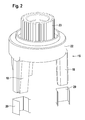
- Fig. 2 shows in a perspective view of the multipart constructed driver 15.
- This comprises a manufactured as an injection molded body 22 made of plastic.
- an outer toothing 23 in order on the driver 15 of the drive wheel 14 (see. Fig. 1 ) transmitted torque on, for example, to a cable mechanism to be able to transfer.
- the driver 15, more precisely the base body 22, has two circumferentially spaced apart by 180 ° axial, pin-like projections 18 which serve to transmit torque, on the one hand for introducing a driven-side torque in the snare element 12 according to Fig. 1 and on the other hand for receiving a drive side via the drive wheel 14 (see. Fig. 1 ) introduced torque.
- the driver 15 comprises two clippable metal elements 20 for fixing to the extensions 18, with the aim of increasing the robustness of the multi-part carrier 15.
- the free ends 17 of the snare element 12 are not supported directly on the extensions 18, but only indirectly on the projections 18 on the metal elements 9, the immediate, i. directly, with the free ends 17 of the snare element 12 cooperate.
- the driver 15 is shown in the assembled state. It can be seen that the metal elements 20 are arranged offset in the axial direction. This is due to the fact that the free ends 17 designed as a wrap spring snare element 12 are spaced apart in the axial direction.
- the metal elements 20 each enclose a plastic section 13 of the main body 22 formed by a respective extension section.
- Fig. 4 results in the metal elements 20 on a common side in each case a contact region 25 for direct contact each of a free end 17 of the loop element 12.
- impermissible surface pressures as they could occur in the case of pure plastic projections 18 in case of blocking, can be reliably avoided.
- the bending stresses in the extensions 18 are reduced by the metal elements 20, that the forces originating from the free ends 17 are introduced into the extensions 18 over a larger area.
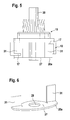
- the metal element 20a has a plate-like central region 27 with a passage opening 28. By means of the passage opening 28, the metal element 20a is mounted in a drive journal 30 of the driver 15.
- the central region 27 is arranged in a plane below the driver 15 or its extensions 18. From the central region 27 project in its outer region two, offset by 180 ° to each other arranged contact portions 31 in the direction of the extensions 18, wherein the two contact portions 31 are formed differently long according to the different axial arrangement of the two free ends 17 of the loop element 12.
- the contact portions 31 are in this case arranged between the free ends 17 and the extensions 18 in the receiving pockets 16 of the driver.
- the driver 15a has means for reducing the bending stresses due to the introduction of force of the free ends 17 of the loop element 12 in the driver 15a. These means consist in a special geometric design of the driver 15a.
- the driver 15a has a modified extension 18a which, viewed in a plane transverse to the longitudinal direction of the driver 15a, has an angular range of at least approximately 10 °, in particular between 30 ° and 120 °, up to the illustrated occupies about 180 °.
- the two end faces 33, 34 delimiting the extension 18a serve as a counterpart or contact surface for the two free ends 17 of the looping element 12.
- the extension 18a which is generally wider than the extensions 18, in particular the bending stress of the extension 18a on the base 35 of the carrier 15a is reduced.
- the driver 15a is shown, as it additionally cooperates with a metal element 20b, which substantially in the Fig. 2 to 4 represented metal element 20 corresponds.
- FIGS. 9 and 10 is a modified metal element 20c for use on the driver 15a (alternatively, an insert on the driver 15 is possible) is shown.
- the metal element 20c on an additional support portion 38 which engages through an opening formed in the driver 15a opening 39 and rests against the underside 40 of the driver 15a.
- a bending moment transmitted by the free end 17 of the loop element 12 is transmitted via the support section 38 to the catch 15a, as a result of which an at least partial relief of the extension 18a is effected.
- a modified metal element 20d for use with the driver 15 is shown.
- the metal element 20d is formed like a bow and comprises the extension 18 of the driver 15.
- the metal element 20d on the side opposite the contact region 25 has a support portion 38d, which rests on the upper side 41 of the driver 15.
- modified metal element 20e for the driver 15 represents a combination of the metal elements 20c and 20d.
- the metal element 20e has two, arranged on opposite sides support portions 43, 44 which cooperate with the top and bottom of the driver 15.
- the metal elements 20, 20a to 20e are made in particular as a stamped and bent part from sheet metal. Furthermore, it may be provided in the metal elements 20c, 20d, 20e that the support portions 38, 38d, 43, 44 are also surrounded by the plastic of the driver 15, 15a. As a result, the metal elements 20c, 20d, 20e are additionally anchored in the driver 15, 15a, so that additional holding measures on the carrier 15, 15a may possibly be dispensed with.
Landscapes
- Engineering & Computer Science (AREA)
- General Engineering & Computer Science (AREA)
- Mechanical Engineering (AREA)
- Braking Arrangements (AREA)
- Mechanical Operated Clutches (AREA)
- Window Of Vehicle (AREA)
- Power-Operated Mechanisms For Wings (AREA)
Description
- Die Erfindung betrifft eine Lastdrehmomentsperre, insbesondere für Kraftfahrzeuganwendungen, gemäß dem Oberbegriff des Anspruchs 1, sowie ein Aggregat, insbesondere ein Hilfs- und Komfortaggregat, vorzugsweise für Kraftfahrzeuganwendungen, mit einer Lastdrehmomentsperre gemäß Anspruch 15.
- Aus der
DE 197 53 106 C2 ist eine Lastdrehmomentsperre bekannt, die in einem Antriebsstrang eingebaut ist und beim Stillstand des Antriebs selbstständig die vom Abtrieb eingeleiteten Drehmomente sperrt. Die von der Antriebsseite eingeleiteten Drehmomente werden in beide Richtungen übertragen. Zum Blockieren des abtriebsseitigen Drehmomentes wirkt eine Schlingfeder reibschlüssig mit einem Bremskörper zusammen. Die bekannte Lastdrehmomentsperre hat sich bewährt. Es bestehen jedoch Bestrebungen, die Lastdrehmomentsperre robuster zu gestalten, da es insbesondere im Kontaktbereich der Schlingfeder zu dem Kunststoffmitnehmer zu Deformationen des Kunststoffs kommen kann, die auf unzulässige, im Betrieb auftretende Flächenpressungen sowie relativ hohe Biegespannungen zurückzuführen sind. - Weitere Lastmomentdrehsperren sind ebenso aus der
JP-59-029822 GB2 211 565 - Der Erfindung liegt daher die Aufgabe zugrunde, eine robuste Lastdrehmomentsperre anzugeben, die eine erhöhte Lebensdauer aufweist. Bevorzugt soll die Lastdrehmomentsperre kostengünstig herstellbar sein und weiter bevorzugt in Leichtbauweise realisiert werden können. Ferner besteht die Aufgabe darin, ein Aggregat mit einer entsprechend optimierten Lastdrehmomentsperre anzugeben.
- Diese Aufgabe wird hinsichtlich der Lastdrehmomentsperre mit den Merkmalen des Anspruchs 1 sowie hinsichtlich des Aggregates mit den Merkmalen des Anspruchs 15 gelöst. Vorteilhafte Weiterbildungen der Erfindung sind in den Unteransprüchen angegeben. In den Rahmen der Erfindung fallen sämtliche Kombinationen aus zumindest zwei von in der Beschreibung, den Ansprüchen und/oder den Figuren offenbarten Merkmalen.
- Der Erfindung liegt der Gedanke zugrunde, den mindestens einen Kontaktbereich des Mitnehmers, an dem das Schlingelement im Blockierfall anliegt bzw. sich abstützt, mit Mitteln auszustatten, die eine Reduzierung der Biegespannung in dem wenigstens einen Kontaktbereich bewirken.
- Besonders bevorzugt ist eine Ausführungsform, bei der zwei Kontaktbereiche des Mitnehmers, die jeweils mit einem freien Ende des Schlingelementes zusammenwirken, zumindest zum Teil aus Metall ausgebildet sind. Durch eine zumindest teilweise Ausbildung des mindestens einen Kontaktbereichs des Mitnehmers aus Metall können unzulässige Flächenpressungen sowie eine hohe Biegebeanspruchung vermieden werden, wodurch eine Beschädigung des Mitnehmers bei der Einleitung eines zu blockierenden Drehmomentes sicher verhindert werden kann.
- Eine nach dem Konzept der Erfindung ausgebildete Lastdrehmomentsperre eignet sich insbesondere für Kraftfahrzeuganwendungen, wie Schiebedachantriebe, Sitzversteller, Fensterheber, Scheibenwischerantriebe, Getriebe- und Kupplungssteller sowie für elektrische Lenkungen und für den Einsatz in Stellantrieben im Allgemeinen. Die Anwendung einer nach dem Konzept der Erfindung ausgebildeten Lastdrehmomentsperre ist hierauf jedoch nicht beschränkt und kann grundsätzlich bei sämtlichen Motoren bzw. Antrieben und Maschinen eingesetzt werden.
- Ganz besonders bevorzugt ist eine Ausführungsform der Lastdrehmomentsperre, bei der der mit dem Antriebsrad, vorzugsweise durch axiales Eingreifen, gekoppelte Mitnehmer mehrteilig ausgeführt ist, vorzugsweise derart, dass er einen Kunststoff-Grundkörper umfasst, an dem mindestens ein Metallelement zur Bildung mindestens eines Kontaktbereichs festgelegt ist. Ganz besonders bevorzugt handelt es sich bei dem Mitnehmer bzw. bei dem Grundkörper um ein Kunststoff-Spritzgussteil. Durch die Mehrteiligkeit des Mitnehmers (Kunststoffund Metallschutz) wird es möglich, den Kontaktdruck zum Schlingelement so zu verteilen, dass der Grundkörper aus Kunststoff den Belastungen standhält und insgesamt ein kostengünstig herstellbares System erhalten wird.
- Im Hinblick auf die Art und Weise der Festlegung des mindestens einen Metallelementes am Kunststoffabschnitt des Mitnehmers, vorzugsweise an einem Grundkörper des Mitnehmers, gibt es die unterschiedlichsten Möglichkeiten. So ist es beispielsweise möglich, das Metallelement im Spritzgussverfahren teilweise zu umspritzen und auf diese Weise festzulegen. Bei einer alternativen Ausführungsform ist das Metallelement mit dem Kunststoffabschnitt verrastbar bzw. auf diesen aufklipsbar und kann im Nachhinein an diesem auf einfache Weise befestigt werden.
- Auch im Hinblick auf die Ausbildung des Metallelementes gibt es unterschiedliche Möglichkeiten. So ist es beispielsweise möglich, das Metallelement als Hülse oder als einseitig, insbesondere bodenseitig, geschlossenen Topf auszubilden und derart anzuordnen, dass das Metallelement den Kunststoffabschnitt zumindest teilweise abdeckt bzw. umschließt. Auch ist es möglich das Metallelement derart auszubilden, das es von dem Kunststoff des Mitnehmers zumindest teilweise umspritzt ist.
- Darüber hinaus gibt es auch im Hinblick auf die konkrete Ausbildung des Schlingelementes unterschiedliche Möglichkeiten. Besonders bevorzugt ist eine Ausführungsform, bei der das Schlingelement als, insbesondere metallische, Schlingfeder ausgebildet ist, wobei die Schlingfeder bevorzugt mit zwei in axialer Richtung voneinander beabstandeten, vorzugsweise nach radial innen gebogenen, freien Enden mit jeweils einem metallischen Kontaktbereich des Mitnehmers zusammenwirkt. Es sind auch alternative Ausführungsformen des Schlingelementes, beispielsweise als Schlinggliederkette, Schlingband, Schlingseil, od.dgl. möglich. Bevorzugt ist das Schlingelement derart angeordnet, dass dessen freie Enden in Umfangsrichtung gegeneinander sowie voneinander weg bewegbar sind, um das Schlingelement für den Sperrfall reibschlüssig radial innen oder radial außen in Reibschluss mit dem Bremskörper zu bringen.
- Auch im Hinblick auf die Ausbildung des Bremskörpers gibt es unterschiedliche Möglichkeiten. Besonders bevorzugt ist es, wenn der Bremskörper eine zylindrische Reibfläche (Innen- oder Außenmantelfläche) aufweist, wobei sowohl eine Ausführungsform realisierbar ist, bei der das Schlingelement mit dem Innenumfang des Bremskörpers, also mit einer am Innenumfang ausgebildeten Reibfläche, zusammenwirkt oder den Bremskörper umgibt und in diesem Fall reibschlüssig mit einem Außenumfang des Bremskörpers im Blockierfall reibschlüssig zusammenwirkt.
- Die Erfindung führt auch auf ein Aggregat, vorzugsweise ein Hilfs- oder Komfortaggregat, insbesondere für Kraftfahrzeuganwendungen. Bei dem Aggregat kann es sich beispielsweise um einen Motor und/oder eine Maschine handeln. Ganz besonders bevorzugt handelt es sich um einen Verstellantrieb, wie einen Schiebedachantrieb, einen Fensterheberantrieb, einen Sitzverstellantrieb, einen Scheibenwischerantrieb oder einen Getriebe- und/oder Kupplungssteller. Es kann sich auch um eine elektrische Fahrzeuglenkung, etc. handeln. Das Aggregat zeichnet sich dadurch aus, dass dieses mit mindestens einer nach dem Konzept der Erfindung ausgebildeten Lastdrehmomentsperre versehen ist.
- Weitere Vorteile, Merkmale und Einzelheiten der Erfindung ergeben sich aus der nachfolgenden Beschreibung bevorzugter Ausführungsbeispiele sowie anhand der Zeichnungen.
- Diese zeigen in:
- Fig. 1
- in einer perspektivischen, teilgeschnittenen Darstellung eine mögliche Ausführungsform einer Lastdrehmomentsperre (Sperrkupplung),
- Fig. 2
- eine Explosionsdarstellung eines Mitnehmers, bestehend aus einem Kunststoff-Grundkörper und zwei aufklipsbaren Metallelementen,
- Fig. 3
- eine Seitenansicht eines fertig montierten Mitnehmers,
- Fig. 4
- eine in Bezug auf
Fig. 3 um 180° gedrehte Seitenansicht des montierten Mitnehmers, - Fig. 5
- einen Teil der Lastdrehmomentsperre in einer teilweisen geschnittenen perspektivischen Ansicht mit einem modifizierten Metallelement,
- Fig. 6
- das Metallelement gemäß der
Fig. 5 in einer perspektivischen Ansicht, - Fig. 7
- einen modifizierten Mitnehmer in einer perspektivischen Ansicht,
- Fig. 8
- den Mitnehmer gemäß der
Fig. 7 mit einem zusätzlichen Metallelement, ebenfalls in einer perspektivischen Ansicht, - Fig. 9
- ein weiteres modifiziertes Metallelement mit einem Stützabschnitt in perspektivischer Darstellung,
- Fig. 10
- das Metallelement gemäß der
Fig. 10 bei auf dem Mitnehmer montiertem Zustand in perspektivischer Ansicht, - Fig. 11
- ein weiteres modifiziertes Metallelement mit einem Stützabschnitt in perspektivischer Darstellung,
- Fig. 12
- das Metallelement gemäß der
Fig. 11 bei auf dem Mitnehmer montiertem Zustand in perspektivischer Ansicht, - Fig. 13
- ein weiteres modifiziertes Metallelement mit einem Stützabschnitt in perspektivischer Darstellung und
- Fig. 14
- das Metallelement gemäß der
Fig. 13 bei auf dem Mitnehmer montiertem Zustand in perspektivischer Ansicht. - In den Figuren sind gleiche Elemente und Elemente mit der gleichen Funktion mit den gleichen Bezugszeichen gekennzeichnet.
- In
Fig. 1 ist eine mögliche Ausführungsform einer dauergekuppelten, d.h. nicht entkuppelbaren, Lastdrehmomentsperre 1 gezeigt. Diese umfasst ein als metallische Schlingfeder ausgebildetes Schlingelement 12. Das Schlingelement 12 ist in einem hohlzylindrischen Bremskörper 13 aufgenommen und wirkt im Blockierfall mit seinem Außenumfang mit der inneren Umfangsfläche des Bremskörpers 13 zusammen. Bei einer alternativen, an sich bekannten, nicht dargestellten Ausführungsvariante wirkt das Schlingelement 12 mit seinem Innenumfang mit dem, vorzugsweise zylindrischen, Außenumfang eines Bremskörpers zusammen. - Die Lastdrehmomentsperre 1 umfasst ein als Schneckenrad ausgebildetes Antriebsrad 14, das von einer nicht dargestellten, elektromotorisch angetriebenen Getriebeschnecke in beide Umfangsrichtungen antreibbar ist. Das Antriebsrad 14 ist gekoppelt mit einem Mitnehmer 15, der in axialer Richtung in Aufnahmetaschen 16 des Antriebsrades 14 eingreift. Der Mitnehmer 15 dient wiederum zur Übertragung des antriebsseitig eingeleiteten Drehmoments an einen Verstellmechanismus, beispielsweise einen Seilzugmechanismus eines Fensterheberantriebs.
- Das Schlingelement 12 weist zwei in axialer Richtung voneinander beabstandete freie Enden auf, von denen in
Fig. 1 nur ein oberes, nach radial innen gebogenes freies Ende 17 gezeigt ist. Das Antriebsrad 14 wirkt derart mit dem Mitnehmer 15 zusammen, dass, wenn antriebsseitig, d.h. von dem Antriebsrad 14, ein Drehmoment eingeleitet wird, dieses auf den Mitnehmer 15 übertragen wird. Das Schlingelement 12 treibt dann durch, d.h. es wird zusammen mit dem Antriebsrad 14 und dem Mitnehmer 15 relativ zu dem feststehenden Bremskörper 13 verstellt. Für den Fall der abtriebsseitigen Drehmomenteinleitung, also der Drehmomenteinleitung über den Mitnehmer 15, werden die freien Enden 17 des Schlingelementes 12 auseinander bewegt, derart, dass sich der Außenumfang des Schlingelementes 12 vergrößert, wodurch das Schlingelement 12 reibschlüssig mit seinem Außenumfang mit dem Innenumfang des Bremskörpers 13 zusammenwirkt und somit das abtriebsseitige Drehmoment sperrt, also nicht weiter auf das Antriebsrad 14 und damit in Richtung Antriebsmotor, insbesondere einen Elektromotor (nicht dargestellt), übertragen wird. - Bei einer nicht dargestellten Ausführungsvariante einer Lastdrehmomentsperre 1, bei der das Schlingelement 12 mit dem Außenumfang eines Bremskörpers 13 zusammenwirkt, müssen die freien Enden 17, wie zuvor beschrieben, jedoch mit umgekehrten Vorzeichen zueinander verstellt werden, um den Bremseffekt zu bewirken.
- Um die Robustheit der Lastdrehmomentsperre 1 zu erhöhen, ist an jedem axialen Fortsatz 18 (nur einer dargestellt), mittels denen der Mitnehmer 15 axial in die Aufnahmetaschen 16 eingreift, ein Metallelement 20 vorgesehen, an dem sich jeweils ein freies Ende 17 des Schlingelementes 12 zum Blockieren des abtriebsseitigen Drehmomentes abstützt.
- Im Folgenden wird eine erste bevorzugte Ausführungsform des mehrteilig ausgebildeten Mitnehmers 15 anhand der perspektivischen Darstellungen gemäß den
Fig. 2 bis Fig. 4 im Detail erläutert. -
Fig. 2 zeigt in einer perspektivischen Darstellung den mehrteilig aufgebauten Mitnehmer 15. Dieser umfasst einen als Spritzgussteil hergestellten Grundkörper 22 aus Kunststoff. In einem oberen Abschnitt ist der Grundkörper 22 mit einer Außenverzahnung 23 versehen, um das auf den Mitnehmer 15 von dem Antriebsrad 14 (vgl.Fig. 1 ) übertragene Drehmoment weiter, beispielsweise an einen Seilzugmechanismus, übertragen zu können. - Der Mitnehmer 15, genauer der Grundkörper 22, weist zwei in Umfangsrichtung um 180° voneinander beabstandete axiale, zapfenartige Fortsätze 18 auf, die zur Drehmomentübertragung dienen, einerseits zum Einleiten eines abtriebsseitigen Drehmomentes in das Schlingelement 12 gemäß
Fig. 1 und andererseits zur Aufnahme eines antriebsseitig über das Antriebsrad 14 (vgl.Fig. 1 ) eingeleiteten Drehmomentes. - Ferner umfasst der Mitnehmer 15 zwei aufklipsbare Metallelemente 20 zum Festlegen an den Fortsätzen 18, mit dem Ziel, die Robustheit des mehrteiligen Mitnehmers 15 zu erhöhen. Im Gegensatz zum Stand der Technik stützen sich die freien Enden 17 des Schlingelementes 12 nicht unmittelbar an den Fortsätzen 18, sondern nur mittelbar an diesen über die Metallelemente 9 ab, die unmittelbar, d.h. direkt, mit den freien Enden 17 des Schlingelementes 12 zusammenwirken.
- In den
Fig. 3 und Fig. 4 ist jeweils der Mitnehmer 15 im fertig montierten Zustand dargestellt. Zu erkennen ist, dass die Metallelemente 20 in axialer Richtung versetzt angeordnet sind. Dies ist darauf zurückzuführen, dass auch die freien Enden 17 des als Schlingfeder ausgebildeten Schlingelementes 12 in axialer Richtung voneinander beabstandet sind. - Die Metallelemente 20 umschließen jeweils einen von jeweils einem Fortsatzabschnitt gebildeten Kunststoffabschnitt 13 des Grundkörpers 22.
- Wie sich aus
Fig. 4 ergibt, bilden die Metallelemente 20 auf einer gemeinsamen Seite jeweils einen Kontaktbereich 25 zur unmittelbaren Anlage jeweils eines freien Endes 17 des Schlingelementes 12. Auf diese Weise können unzulässige Flächenpressungen, wie sie im Blockierfall bei reinen Kunststoff-Fortsätzen 18 auftreten könnten, sicher vermieden werden. Weiterhin werden durch die Metallelemente 20 die Biegespannungen in den Fortsätzen 18 reduziert, das die von den freien Enden 17 herrührenden Kräfte über einen größeren Bereich in die Fortsätze 18 eingeleitet werden. - In den
Figuren 5 und 6 ist ein modifiziertes Metallelement 20a dargestellt. Das Metallelement 20a weist einen plattenartigen Mittelbereich 27 mit einer Durchgangsöffnung 28 auf. Mittels der Durchgangsöffnung 28 ist das Metallelement 20a in einem Antriebszapfen 30 des Mitnehmers 15 gelagert. Der Mittelbereich 27 ist in einer Ebene unterhalb des Mitnehmers 15 bzw. dessen Fortsätzen 18 angeordnet. Vom Mittelbereich 27 ragen in seinem äußeren Bereich zwei, um 180° zueinander versetzt angeordnete Kontaktabschnitte 31 in Richtung der Fortsätze 18 ab, wobei die beiden Kontaktabschnitte 31 entsprechend der unterschiedlichen axialen Anordnung der beiden freien Enden 17 des Schlingelements 12 unterschiedlich lang ausgebildet sind. Die Kontaktabschnitte 31 sind hierbei zwischen den freien Enden 17 und den Fortsätzen 18 in den Aufnahmetaschen 16 des Mitnehmers angeordnet. - In der
Figur 7 ist ein modifizierter Mitnehmer 15a dargestellt. Der Mitnehmer 15a weist Mittel zur Reduktion der Biegespannungen aufgrund der Krafteinleitung der freien Enden 17 des Schlingelements 12 in den Mitnehmer 15a auf. Diese Mittel bestehen in einer besonderen geometrischen Ausbildung des Mitnehmers 15a. - Hierzu weist der Mitnehmer 15a einen modifizierten Fortsatz 18a auf, der in einer Ebene quer zur Längsrichtung des Mitnehmers 15a betrachtet, einen Winkelbereich von wenigstens etwa 10°, insbesondere zwischen 30° und 120°, bis hin zu den dargestellten etwa 180° einnimmt. Dabei ergibt sich der angesprochene Winkelbereich je nach Beanspruchung bzw. zu übertragenden Kräften sowie in u.a. in Abhängigkeit von dem verwendeten Material. Wesentlich bei dem Mitnehmer 15a ist, dass die beiden den Fortsatz 18a begrenzenden Stirnflächen 33, 34 als Gegen- bzw. Anlagefläche für die beiden freien Enden 17 des Schlingelements 12 dienen. Durch die gegenüber den Fortsätzen 18 üblicherweise breitete Ausbildung des Fortsatzes 18a wird insbesondere die Biegebeanspruchung des Fortsatzes 18a am Grund 35 des Mitnehmers 15a reduziert. Weiterhin kann hierzu bevorzugt vorgesehen sein, dass zumindest im Übergangsbereich des Grundes 35 zu den Stirnflächen 33, 34 jeweils ein Radius 36 ausgebildet ist, der die Biegebeanspruchung bzw. die Kerbwirkung weiter reduziert.
- In der
Fig. 8 ist der Mitnehmer 15a dargestellt, wie er zusätzlich mit einem Metallelement 20b zusammenwirkt, das im Wesentlichen dem in denFig. 2 bis 4 dargestellten Metallelement 20 entspricht. - In den
Fig. 9 und 10 ist ein modifiziertes Metallelement 20c zur Verwendung an dem Mitnehmer 15a (alternativ hierzu ist auch ein Einsatz an dem Mitnehmer 15 möglich) dargestellt. Hierbei weist das Metallelement 20c einen zusätzlichen Stützabschnitt 38 auf, der einen in dem Mitnehmer 15a ausgebildeten Durchbruch 39 durchgreift und sich an der Unterseite 40 des Mitnehmers 15a anliegt. Hierdurch wird ein von dem freien Ende 17 des Schlingelements 12 übertragenes Biegemoment über den Stützabschnitt 38 auf den Mitnehmer 15a übertragen, wodurch eine zumindest teilweise Entlastung des Fortsatzes 18a bewirkt wird. - In den
Fig. 11 und 12 ist ein modifiziertes Metallelement 20d zur Verwendung am Mitnehmer 15 dargestellt. Hierbei ist das Metallelement 20d bügelartig ausgebildet und umfasst den Fortsatz 18 des Mitnehmers 15. Weiterhin weist das Metallelement 20d auf der dem Kontaktbereich 25 gegenüberliegenden Seite einen Stützabschnitt 38d auf, der an der Oberseite 41 des Mitnehmers 15 aufliegt. - Das in den
Fig. 13 und 14 dargestellte modifizierte Metallelement 20e für den Mitnehmer 15 stellt eine Kombination der Metallelemente 20c und 20d dar. Hierzu weist das Metallelement 20e zwei, auf gegenüberliegenden Seiten angeordnete Stützbereiche 43, 44 auf, die mit der Ober- bzw. Unterseite des Mitnehmers 15 zusammenwirken. - Ergänzend wird erwähnt, dass die Metallelemente 20, 20a bis 20e insbesondere als Stanzbiegeteil aus Blech hergestellt sind. Weiterhin kann es bei den Metallelementen 20c, 20d, 20e vorgesehen sein, dass die Stützabschnitte 38, 38d, 43, 44 auch vom Kunststoff des Mitnehmers 15, 15a umschlossen sind. Dadurch werden die Metallelemente 20c, 20d, 20e zusätzlich in dem Mitnehmer 15, 15a verankert, so dass auf zusätzliche Haltemaßnahmen am Mitnehmer 15, 15a ggf. verzichtet werden kann.
Claims (14)
- Lastdrehmomentsperre (1), umfassend ein zum Sperren eines Drehmomentes mit einem Bremskörper (13) reibschlüssig zusammenwirkendes Schlingelement (12), sowie ein Antriebsrad (14), welches drehmomentübertragend mit einem axial in das Antriebsrad (14) eingreifenden, mindestens einen Kontaktbereich (25) zum Schlingelement (12) aufweisenden Mitnehmer (15; 15a) gekoppelt ist, mit dem ein zu blockierendes Drehmoment in das Schlingelement (12) einleitbar ist, und das Schlingelement (12) als Schlingfeder ausgebildet ist, wobei die Schlingfeder mit zwei in axialer Richtung voneinander beabstandeten, nach radial innen gebogenen, freien Enden (17) mit jeweils einem Kontaktbereich (25) des Mitnehmers (15, 15a) zusammenwirkt, wobei die freien Enden (17) in Umfangsrichtung gegeneinander, sowie voneinander weg bewegbar sind, um das Schlingelement (12) für den Sperrfall reibschlüssig radial innen oder radial außen in Reibschluss mit dem Bremskörper (13) zu bringen,
dadurch gekennzeichnet, dass
der Mitnehmer (15;15a) Mittel zur Reduzierung der Biegespannung in dem wenigsten einen Kontaktbereich (25) aufweist, wobei ein Grundkörper des Mitnehmers (15;15a) aus Kunststoff und der Kontaktbereich des Mitnehmers (15;15a) aus Metal ausgebildet ist. - Lastdrehmomentsperre nach Anspruch 1,
dadurch gekennzeichnet,
dass der Kontaktbereich (25) von einem an einem Kunststoffabschnitt (24) des Mitnehmers (15; 15a) angeordneten Metallelement (20, 20a bis 20e) gebildet ist. - Lastdrehmomentsperre nach einem der Ansprüche 2 oder 3,
dadurch gekennzeichnet,
dass der Mitnehmer (15; 15a) bis auf das mindestens eine, mindestens einen Kontaktbereich (25) bildende Metallelemente (20, 20a bis 20e) vollständig aus Kunststoff, insbesondere als Kunststoffspritzgussteil, ausgebildet ist. - Lastdrehmomentsperre nach Anspruch 3,
dadurch gekennzeichnet,
dass das Metallelement (20, 20a bis 20e) auf den Kunststoffabschnitt (24) aufgeklipst ist. - Lastdrehmomentsperre nach einem der Ansprüche 2 bis 4,
dadurch gekennzeichnet,
dass das Metallelement (20, 20a bis 20e) als den Kunststoffabschnitt (24) zumindest teilweise umschließende Hülse oder Topf ausgebildet ist. - Lastdrehmomentsperre nach Anspruch 5,
dadurch gekennzeichnet,
dass das Metallelement (20c; 20d; 20e) wenigstens einen, insbesondere senkrecht zum Kontaktbereich (25) angeordneten Stützabschnitt (38; 38d; 43, 44) aufweist, der in dem Mitnehmer (15; 15a) eingebettet ist oder sich an einer Oberfläche des Mitnehmers (15; 15a) abstützt. - Lastdrehmomentsperre nach Anspruch 2 oder 3,
dadurch gekennzeichnet,
dass das Metallelemente (20a) auf einem Lagerzapfen (30) für den Mitnehmer (15) drehbar gelagert ist und, dass das Metallelement (20a) wenigstens einen achsparallel zum Lagerzapfen (30) angeordneten Kontaktabschnitt (31) aufweist, der mit dem wenigstens einen Kontaktbereich (25) des Mitnehmers (15) zusammenwirkt. - Lastdrehmomentsperre nach Anspruch 7,
dadurch gekennzeichnet,
dass das Metallelement (20a) einen Mittelbereich (27) aufweist, an dessen äußerem Bereich jeweils ein Kontaktabschnitt (31) angeordnet ist. - Lastdrehmomentsperre nach Anspruch 8,
dadurch gekennzeichnet,
dass der Mittelbereich (27) in einer Ebene unterhalb des Mitnehmers (15) angeordnet ist. - Lastdrehmomentsperre nach einem der Ansprüche 2 bis 9,
dadurch gekennzeichnet,
dass das Metallelement (20, 20a bis 20e) als Stanzbiegeteil ausgebildet ist. - Lastdrehmomentsperre nach Anspruch 1,
dadurch gekennzeichnet,
dass die als Kontaktflächen wirkenden Stirnflächen (33, 34) an einem Fortsatz (18a) eines einzigen Mitnehmers (15a) angeordnet ist und, dass im Übergangsbereich von den Stirnflächen (33, 34) zu einem Grund (35) des Mitnehmers (15a) zumindest an der Seite der Stimflächen (33, 34) ein Radius (36) ausgebildet ist. - Lastdrehmomentsperre nach Anspruch 11,
dadurch gekennzeichnet,
dass der Fortsatz (18a) quer zur Längsachse des Mitnehmers (15a) betrachtet einen Winkelbereich von wenigstens 10" überdeckt. - Lastdrehmomentsperre nach einem der vorhergehenden Ansprüche,
dadurch gekennzeichnet,
dass das Schlingelement (12) als Schlingfeder, Schlinggliederkette, Schlingband, oder Schlingseil ausgebildet ist. - Aggregat, insbesondere für Kraftfahrzeuganwendungen, insbesondere Motor, Maschine, Verstellantrieb, Schiebedachantrieb, Fensterheberantrieb, Scheibenwischerantrieb, Getriebe- und/oder Kupplungssteller, elektrische Kraftfahrzeuglenkung, mit einer Lastdrehmomentsperre (1) nach einem der vorhergehenden Ansprüche.
Applications Claiming Priority (3)
| Application Number | Priority Date | Filing Date | Title |
|---|---|---|---|
| DE102009000563 | 2009-02-03 | ||
| DE102010001245A DE102010001245A1 (de) | 2009-02-03 | 2010-01-27 | Lastdrehmomentsperre sowie Aggregat mit Lastdrehmomentsperre |
| PCT/EP2010/050885 WO2010089232A1 (de) | 2009-02-03 | 2010-01-27 | Lastdrehmomentsperre sowie aggregat mit lastdrehmomentsperre |
Publications (2)
| Publication Number | Publication Date |
|---|---|
| EP2394070A1 EP2394070A1 (de) | 2011-12-14 |
| EP2394070B1 true EP2394070B1 (de) | 2014-10-01 |
Family
ID=42077524
Family Applications (1)
| Application Number | Title | Priority Date | Filing Date |
|---|---|---|---|
| EP10701523.2A Not-in-force EP2394070B1 (de) | 2009-02-03 | 2010-01-27 | Lastdrehmomentsperre sowie aggregat mit lastdrehmomentsperre |
Country Status (7)
| Country | Link |
|---|---|
| US (1) | US8857595B2 (de) |
| EP (1) | EP2394070B1 (de) |
| KR (1) | KR101712806B1 (de) |
| CN (1) | CN102301150B (de) |
| BR (1) | BRPI1007898A2 (de) |
| DE (1) | DE102010001245A1 (de) |
| WO (1) | WO2010089232A1 (de) |
Families Citing this family (19)
| Publication number | Priority date | Publication date | Assignee | Title |
|---|---|---|---|---|
| DE102010003657A1 (de) * | 2010-04-06 | 2011-10-06 | Robert Bosch Gmbh | Lastdrehmomentsperre und Aggregat mit einer Lastdrehmomentsperre |
| US9457768B2 (en) | 2011-04-21 | 2016-10-04 | Pylon Manufacturing Corp. | Vortex damping wiper blade |
| WO2013016493A1 (en) | 2011-07-28 | 2013-01-31 | Pylon Manufacturing Corp. | Windshield wiper adapter, connector and assembly |
| US9108595B2 (en) | 2011-07-29 | 2015-08-18 | Pylon Manufacturing Corporation | Windshield wiper connector |
| US20130219649A1 (en) | 2012-02-24 | 2013-08-29 | Pylon Manufacturing Corp. | Wiper blade |
| US10723322B2 (en) | 2012-02-24 | 2020-07-28 | Pylon Manufacturing Corp. | Wiper blade with cover |
| CA2865292C (en) | 2012-02-24 | 2018-03-13 | Pylon Manufacturing Corp. | Wiper blade |
| US10829092B2 (en) | 2012-09-24 | 2020-11-10 | Pylon Manufacturing Corp. | Wiper blade with modular mounting base |
| EP2971822A4 (de) * | 2013-03-15 | 2017-07-26 | Eaton Corporation | Verbesserte konstruktionen für lasttragende strukturen, vorteilhafte metall-kunststoff-verbundkörperkonstruktionen, verfahren zur herstellung davon und anordnung, systeme und verfahren |
| US10166951B2 (en) | 2013-03-15 | 2019-01-01 | Pylon Manufacturing Corp. | Windshield wiper connector |
| US9505380B2 (en) | 2014-03-07 | 2016-11-29 | Pylon Manufacturing Corp. | Windshield wiper connector and assembly |
| DE102015205870A1 (de) * | 2015-04-01 | 2016-10-06 | Robert Bosch Gmbh | Wischerarmanbindung |
| US10363905B2 (en) | 2015-10-26 | 2019-07-30 | Pylon Manufacturing Corp. | Wiper blade |
| CN109311451B (zh) | 2016-05-19 | 2022-08-23 | 电缆塔制造有限公司 | 挡风玻璃雨刮器片 |
| WO2017201458A1 (en) | 2016-05-19 | 2017-11-23 | Pylon Manufacturing Corp. | Windshield wiper connector |
| AU2017268008A1 (en) | 2016-05-19 | 2018-11-22 | Pylon Manufacturing Corp. | Windshield wiper connector |
| WO2017201485A1 (en) | 2016-05-19 | 2017-11-23 | Pylon Manufacturing Corp. | Windshield wiper connector |
| US11040705B2 (en) | 2016-05-19 | 2021-06-22 | Pylon Manufacturing Corp. | Windshield wiper connector |
| DE102022130072B3 (de) * | 2022-11-14 | 2024-03-28 | Thyssenkrupp Ag | Zahnriemenscheibe für einen Zahnriementrieb einer Kraftfahrzeuglenkung, Lenkantrieb für ein Lenksystem eines Kraftfahrzeugs und Lenksystem für ein Kraftfahrzeug |
Citations (1)
| Publication number | Priority date | Publication date | Assignee | Title |
|---|---|---|---|---|
| JPS5929822A (ja) * | 1982-08-10 | 1984-02-17 | Toshiba Corp | スプリングクラツチ装置 |
Family Cites Families (12)
| Publication number | Priority date | Publication date | Assignee | Title |
|---|---|---|---|---|
| US1877288A (en) * | 1929-02-01 | 1932-09-13 | Ternstedt Mfg Co | Antirattling device for alpha window regulator clutch |
| JPS58191327A (ja) * | 1982-05-04 | 1983-11-08 | Aisin Seiki Co Ltd | スプリングカツプラ装置 |
| JPS60245841A (ja) * | 1984-05-16 | 1985-12-05 | Nippon Denso Co Ltd | 逆転防止装置 |
| DE3633337A1 (de) * | 1986-10-01 | 1988-04-07 | Teves Gmbh Alfred | Bolzen- bzw. daempfungselement fuer schwimmsattel-teilbelagscheibenbremsen, insbesondere fuer kraftfahrzeuge |
| US4926987A (en) | 1987-01-13 | 1990-05-22 | Ohi Seisakusho Co., Ltd. | One-way transmission device |
| JP2803933B2 (ja) * | 1991-12-05 | 1998-09-24 | 三田工業株式会社 | バネクラッチ構造 |
| JP2547620Y2 (ja) * | 1991-12-17 | 1997-09-10 | 株式会社ミツバ | 逆転防止装置 |
| US5177662A (en) * | 1992-02-05 | 1993-01-05 | Johnson Service Company | Capacitance humidity sensor |
| DE19753106C2 (de) | 1996-12-09 | 2000-05-04 | Guido Schneider | Lastdrehmomentsperre |
| CN1107819C (zh) * | 1999-07-13 | 2003-05-07 | 王跃 | 自动离合器 |
| JP2006090533A (ja) | 2004-09-27 | 2006-04-06 | Gkn ドライブライン トルクテクノロジー株式会社 | トルク伝達装置 |
| DE102010003657A1 (de) * | 2010-04-06 | 2011-10-06 | Robert Bosch Gmbh | Lastdrehmomentsperre und Aggregat mit einer Lastdrehmomentsperre |
-
2010
- 2010-01-27 EP EP10701523.2A patent/EP2394070B1/de not_active Not-in-force
- 2010-01-27 KR KR1020117018145A patent/KR101712806B1/ko not_active Expired - Fee Related
- 2010-01-27 CN CN201080006365.5A patent/CN102301150B/zh not_active Expired - Fee Related
- 2010-01-27 US US13/147,064 patent/US8857595B2/en not_active Expired - Fee Related
- 2010-01-27 BR BRPI1007898-3A patent/BRPI1007898A2/pt not_active IP Right Cessation
- 2010-01-27 DE DE102010001245A patent/DE102010001245A1/de not_active Withdrawn
- 2010-01-27 WO PCT/EP2010/050885 patent/WO2010089232A1/de not_active Ceased
Patent Citations (1)
| Publication number | Priority date | Publication date | Assignee | Title |
|---|---|---|---|---|
| JPS5929822A (ja) * | 1982-08-10 | 1984-02-17 | Toshiba Corp | スプリングクラツチ装置 |
Also Published As
| Publication number | Publication date |
|---|---|
| EP2394070A1 (de) | 2011-12-14 |
| US8857595B2 (en) | 2014-10-14 |
| KR20110122673A (ko) | 2011-11-10 |
| CN102301150A (zh) | 2011-12-28 |
| CN102301150B (zh) | 2014-06-04 |
| DE102010001245A1 (de) | 2010-08-05 |
| WO2010089232A1 (de) | 2010-08-12 |
| BRPI1007898A2 (pt) | 2015-09-01 |
| US20120152690A1 (en) | 2012-06-21 |
| KR101712806B1 (ko) | 2017-03-07 |
Similar Documents
| Publication | Publication Date | Title |
|---|---|---|
| EP2394070A1 (de) | Lastdrehmomentsperre sowie aggregat mit lastdrehmomentsperre | |
| EP1552097A1 (de) | Getriebevorrichtung, insbesondere für verstelleinrichtungen in kraftfahrzeugen | |
| WO2003024740A1 (de) | Beschlag für einen fahrzeugsitz | |
| DE102012103147A1 (de) | Loslager für ein lenkgetriebe | |
| DE102009046080A1 (de) | Getriebe-Antriebseinheit | |
| DE10342074B4 (de) | Getriebeeinheit und Motor-Getriebeeinheit für Seil-Fensterheber | |
| EP3839186B1 (de) | Fensterheberbaugruppe mit sicherungselement und sicherungsabschnitt für die sicherung eines zugmittels | |
| EP1716306B1 (de) | Gehäuse zur aufnahme einer seiltrommel | |
| EP2235311B1 (de) | Getriebeeinheit sowie antriebs-getriebeeinheit | |
| DE102015102141B4 (de) | Transmitter für ein Schaltgetriebe für ein Kraftfahrzeug, Baugruppe mit Transmitter, Getriebewelle und Gangrad sowie Getriebe | |
| DE10346967A1 (de) | Gurtaufroller für Sicherheitsgurtvorrichtungen | |
| EP3700802B1 (de) | Vorspanneinrichtung | |
| EP2466163B1 (de) | Lastdrehmomentsperre für eine Getriebe-Antriebseinheit und Aggregat mit einer Lastdrehmomentsperre | |
| EP1589244B1 (de) | Mitnehmereinheit mit axial vorgespannter Mitnehmerscheibe | |
| EP2556266B1 (de) | Lastdrehmomentsperre und aggregat mit einer lastdrehmomentsperre | |
| DE10203006A1 (de) | Beschlag für einen Fahrzeugsitz | |
| DE102005060796B4 (de) | Neigungseinstellbeschlag für Lehnen von Sitzen, insbesondere Kraftfahrzeugsitzen | |
| EP1899628B1 (de) | Getriebe-antriebseinheit | |
| DE102013206941A1 (de) | Lastdrehmomentsperre und Getriebe-Antriebseinrichtung mit einer Lastdrehmomentsperre | |
| EP3759374B1 (de) | Fliehkraftpendeleinrichtung mit gewellter federscheibe; kupplungsscheibe sowie antriebsstrang | |
| DE102006014763A1 (de) | Zahnrad | |
| DE102012216987A1 (de) | Getriebe-Antriebseinheit | |
| WO2014067820A1 (de) | Antriebsvorrichtung für ein verstellbares element eines fahrzeugs | |
| DE102013207565A1 (de) | Lastdrehmomentsperre und Aggregat mit einer Lastdrehmomentsperre | |
| DE102012211329A1 (de) | Getriebe-Antriebseinheit |
Legal Events
| Date | Code | Title | Description |
|---|---|---|---|
| PUAI | Public reference made under article 153(3) epc to a published international application that has entered the european phase |
Free format text: ORIGINAL CODE: 0009012 |
|
| 17P | Request for examination filed |
Effective date: 20110905 |
|
| AK | Designated contracting states |
Kind code of ref document: A1 Designated state(s): AT BE BG CH CY CZ DE DK EE ES FI FR GB GR HR HU IE IS IT LI LT LU LV MC MK MT NL NO PL PT RO SE SI SK SM TR |
|
| DAX | Request for extension of the european patent (deleted) | ||
| 17Q | First examination report despatched |
Effective date: 20130507 |
|
| GRAP | Despatch of communication of intention to grant a patent |
Free format text: ORIGINAL CODE: EPIDOSNIGR1 |
|
| INTG | Intention to grant announced |
Effective date: 20140710 |
|
| GRAS | Grant fee paid |
Free format text: ORIGINAL CODE: EPIDOSNIGR3 |
|
| GRAA | (expected) grant |
Free format text: ORIGINAL CODE: 0009210 |
|
| AK | Designated contracting states |
Kind code of ref document: B1 Designated state(s): AT BE BG CH CY CZ DE DK EE ES FI FR GB GR HR HU IE IS IT LI LT LU LV MC MK MT NL NO PL PT RO SE SI SK SM TR |
|
| REG | Reference to a national code |
Ref country code: GB Ref legal event code: FG4D Free format text: NOT ENGLISH |
|
| REG | Reference to a national code |
Ref country code: AT Ref legal event code: REF Ref document number: 689693 Country of ref document: AT Kind code of ref document: T Effective date: 20141015 Ref country code: CH Ref legal event code: EP |
|
| REG | Reference to a national code |
Ref country code: IE Ref legal event code: FG4D Free format text: LANGUAGE OF EP DOCUMENT: GERMAN |
|
| REG | Reference to a national code |
Ref country code: DE Ref legal event code: R096 Ref document number: 502010007980 Country of ref document: DE Effective date: 20141113 |
|
| REG | Reference to a national code |
Ref country code: NL Ref legal event code: VDEP Effective date: 20141001 |
|
| REG | Reference to a national code |
Ref country code: LT Ref legal event code: MG4D |
|
| PG25 | Lapsed in a contracting state [announced via postgrant information from national office to epo] |
Ref country code: NL Free format text: LAPSE BECAUSE OF FAILURE TO SUBMIT A TRANSLATION OF THE DESCRIPTION OR TO PAY THE FEE WITHIN THE PRESCRIBED TIME-LIMIT Effective date: 20141001 |
|
| PG25 | Lapsed in a contracting state [announced via postgrant information from national office to epo] |
Ref country code: IS Free format text: LAPSE BECAUSE OF FAILURE TO SUBMIT A TRANSLATION OF THE DESCRIPTION OR TO PAY THE FEE WITHIN THE PRESCRIBED TIME-LIMIT Effective date: 20150201 Ref country code: NO Free format text: LAPSE BECAUSE OF FAILURE TO SUBMIT A TRANSLATION OF THE DESCRIPTION OR TO PAY THE FEE WITHIN THE PRESCRIBED TIME-LIMIT Effective date: 20150101 Ref country code: LT Free format text: LAPSE BECAUSE OF FAILURE TO SUBMIT A TRANSLATION OF THE DESCRIPTION OR TO PAY THE FEE WITHIN THE PRESCRIBED TIME-LIMIT Effective date: 20141001 Ref country code: PT Free format text: LAPSE BECAUSE OF FAILURE TO SUBMIT A TRANSLATION OF THE DESCRIPTION OR TO PAY THE FEE WITHIN THE PRESCRIBED TIME-LIMIT Effective date: 20150202 Ref country code: CZ Free format text: LAPSE BECAUSE OF FAILURE TO SUBMIT A TRANSLATION OF THE DESCRIPTION OR TO PAY THE FEE WITHIN THE PRESCRIBED TIME-LIMIT Effective date: 20141001 Ref country code: FI Free format text: LAPSE BECAUSE OF FAILURE TO SUBMIT A TRANSLATION OF THE DESCRIPTION OR TO PAY THE FEE WITHIN THE PRESCRIBED TIME-LIMIT Effective date: 20141001 Ref country code: ES Free format text: LAPSE BECAUSE OF FAILURE TO SUBMIT A TRANSLATION OF THE DESCRIPTION OR TO PAY THE FEE WITHIN THE PRESCRIBED TIME-LIMIT Effective date: 20141001 |
|
| PG25 | Lapsed in a contracting state [announced via postgrant information from national office to epo] |
Ref country code: PL Free format text: LAPSE BECAUSE OF FAILURE TO SUBMIT A TRANSLATION OF THE DESCRIPTION OR TO PAY THE FEE WITHIN THE PRESCRIBED TIME-LIMIT Effective date: 20141001 Ref country code: CY Free format text: LAPSE BECAUSE OF FAILURE TO SUBMIT A TRANSLATION OF THE DESCRIPTION OR TO PAY THE FEE WITHIN THE PRESCRIBED TIME-LIMIT Effective date: 20141001 Ref country code: LV Free format text: LAPSE BECAUSE OF FAILURE TO SUBMIT A TRANSLATION OF THE DESCRIPTION OR TO PAY THE FEE WITHIN THE PRESCRIBED TIME-LIMIT Effective date: 20141001 Ref country code: HR Free format text: LAPSE BECAUSE OF FAILURE TO SUBMIT A TRANSLATION OF THE DESCRIPTION OR TO PAY THE FEE WITHIN THE PRESCRIBED TIME-LIMIT Effective date: 20141001 Ref country code: GR Free format text: LAPSE BECAUSE OF FAILURE TO SUBMIT A TRANSLATION OF THE DESCRIPTION OR TO PAY THE FEE WITHIN THE PRESCRIBED TIME-LIMIT Effective date: 20150102 Ref country code: SE Free format text: LAPSE BECAUSE OF FAILURE TO SUBMIT A TRANSLATION OF THE DESCRIPTION OR TO PAY THE FEE WITHIN THE PRESCRIBED TIME-LIMIT Effective date: 20141001 |
|
| PG25 | Lapsed in a contracting state [announced via postgrant information from national office to epo] |
Ref country code: BE Free format text: LAPSE BECAUSE OF NON-PAYMENT OF DUE FEES Effective date: 20150131 |
|
| REG | Reference to a national code |
Ref country code: DE Ref legal event code: R097 Ref document number: 502010007980 Country of ref document: DE |
|
| PG25 | Lapsed in a contracting state [announced via postgrant information from national office to epo] |
Ref country code: SK Free format text: LAPSE BECAUSE OF FAILURE TO SUBMIT A TRANSLATION OF THE DESCRIPTION OR TO PAY THE FEE WITHIN THE PRESCRIBED TIME-LIMIT Effective date: 20141001 Ref country code: DK Free format text: LAPSE BECAUSE OF FAILURE TO SUBMIT A TRANSLATION OF THE DESCRIPTION OR TO PAY THE FEE WITHIN THE PRESCRIBED TIME-LIMIT Effective date: 20141001 Ref country code: RO Free format text: LAPSE BECAUSE OF FAILURE TO SUBMIT A TRANSLATION OF THE DESCRIPTION OR TO PAY THE FEE WITHIN THE PRESCRIBED TIME-LIMIT Effective date: 20141001 Ref country code: EE Free format text: LAPSE BECAUSE OF FAILURE TO SUBMIT A TRANSLATION OF THE DESCRIPTION OR TO PAY THE FEE WITHIN THE PRESCRIBED TIME-LIMIT Effective date: 20141001 |
|
| PLBE | No opposition filed within time limit |
Free format text: ORIGINAL CODE: 0009261 |
|
| STAA | Information on the status of an ep patent application or granted ep patent |
Free format text: STATUS: NO OPPOSITION FILED WITHIN TIME LIMIT |
|
| REG | Reference to a national code |
Ref country code: CH Ref legal event code: PL |
|
| PG25 | Lapsed in a contracting state [announced via postgrant information from national office to epo] |
Ref country code: LU Free format text: LAPSE BECAUSE OF FAILURE TO SUBMIT A TRANSLATION OF THE DESCRIPTION OR TO PAY THE FEE WITHIN THE PRESCRIBED TIME-LIMIT Effective date: 20150127 |
|
| 26N | No opposition filed |
Effective date: 20150702 |
|
| GBPC | Gb: european patent ceased through non-payment of renewal fee |
Effective date: 20150127 |
|
| PG25 | Lapsed in a contracting state [announced via postgrant information from national office to epo] |
Ref country code: MC Free format text: LAPSE BECAUSE OF FAILURE TO SUBMIT A TRANSLATION OF THE DESCRIPTION OR TO PAY THE FEE WITHIN THE PRESCRIBED TIME-LIMIT Effective date: 20141001 |
|
| PG25 | Lapsed in a contracting state [announced via postgrant information from national office to epo] |
Ref country code: LI Free format text: LAPSE BECAUSE OF NON-PAYMENT OF DUE FEES Effective date: 20150131 Ref country code: GB Free format text: LAPSE BECAUSE OF NON-PAYMENT OF DUE FEES Effective date: 20150127 Ref country code: CH Free format text: LAPSE BECAUSE OF NON-PAYMENT OF DUE FEES Effective date: 20150131 |
|
| REG | Reference to a national code |
Ref country code: IE Ref legal event code: MM4A |
|
| REG | Reference to a national code |
Ref country code: FR Ref legal event code: PLFP Year of fee payment: 7 |
|
| PG25 | Lapsed in a contracting state [announced via postgrant information from national office to epo] |
Ref country code: IE Free format text: LAPSE BECAUSE OF NON-PAYMENT OF DUE FEES Effective date: 20150127 |
|
| PG25 | Lapsed in a contracting state [announced via postgrant information from national office to epo] |
Ref country code: SI Free format text: LAPSE BECAUSE OF FAILURE TO SUBMIT A TRANSLATION OF THE DESCRIPTION OR TO PAY THE FEE WITHIN THE PRESCRIBED TIME-LIMIT Effective date: 20141001 |
|
| REG | Reference to a national code |
Ref country code: AT Ref legal event code: MM01 Ref document number: 689693 Country of ref document: AT Kind code of ref document: T Effective date: 20150127 |
|
| PG25 | Lapsed in a contracting state [announced via postgrant information from national office to epo] |
Ref country code: AT Free format text: LAPSE BECAUSE OF NON-PAYMENT OF DUE FEES Effective date: 20150127 |
|
| PG25 | Lapsed in a contracting state [announced via postgrant information from national office to epo] |
Ref country code: MT Free format text: LAPSE BECAUSE OF FAILURE TO SUBMIT A TRANSLATION OF THE DESCRIPTION OR TO PAY THE FEE WITHIN THE PRESCRIBED TIME-LIMIT Effective date: 20141001 |
|
| REG | Reference to a national code |
Ref country code: FR Ref legal event code: PLFP Year of fee payment: 8 |
|
| PG25 | Lapsed in a contracting state [announced via postgrant information from national office to epo] |
Ref country code: BG Free format text: LAPSE BECAUSE OF FAILURE TO SUBMIT A TRANSLATION OF THE DESCRIPTION OR TO PAY THE FEE WITHIN THE PRESCRIBED TIME-LIMIT Effective date: 20141001 Ref country code: HU Free format text: LAPSE BECAUSE OF FAILURE TO SUBMIT A TRANSLATION OF THE DESCRIPTION OR TO PAY THE FEE WITHIN THE PRESCRIBED TIME-LIMIT; INVALID AB INITIO Effective date: 20100127 Ref country code: SM Free format text: LAPSE BECAUSE OF FAILURE TO SUBMIT A TRANSLATION OF THE DESCRIPTION OR TO PAY THE FEE WITHIN THE PRESCRIBED TIME-LIMIT Effective date: 20141001 |
|
| PG25 | Lapsed in a contracting state [announced via postgrant information from national office to epo] |
Ref country code: TR Free format text: LAPSE BECAUSE OF FAILURE TO SUBMIT A TRANSLATION OF THE DESCRIPTION OR TO PAY THE FEE WITHIN THE PRESCRIBED TIME-LIMIT Effective date: 20141001 |
|
| REG | Reference to a national code |
Ref country code: FR Ref legal event code: PLFP Year of fee payment: 9 |
|
| PGFP | Annual fee paid to national office [announced via postgrant information from national office to epo] |
Ref country code: IT Payment date: 20180126 Year of fee payment: 9 |
|
| PG25 | Lapsed in a contracting state [announced via postgrant information from national office to epo] |
Ref country code: MK Free format text: LAPSE BECAUSE OF FAILURE TO SUBMIT A TRANSLATION OF THE DESCRIPTION OR TO PAY THE FEE WITHIN THE PRESCRIBED TIME-LIMIT Effective date: 20141001 |
|
| PGFP | Annual fee paid to national office [announced via postgrant information from national office to epo] |
Ref country code: FR Payment date: 20190122 Year of fee payment: 10 |
|
| REG | Reference to a national code |
Ref country code: DE Ref legal event code: R084 Ref document number: 502010007980 Country of ref document: DE |
|
| PG25 | Lapsed in a contracting state [announced via postgrant information from national office to epo] |
Ref country code: IT Free format text: LAPSE BECAUSE OF NON-PAYMENT OF DUE FEES Effective date: 20190127 |
|
| PG25 | Lapsed in a contracting state [announced via postgrant information from national office to epo] |
Ref country code: FR Free format text: LAPSE BECAUSE OF NON-PAYMENT OF DUE FEES Effective date: 20200131 |
|
| PGFP | Annual fee paid to national office [announced via postgrant information from national office to epo] |
Ref country code: DE Payment date: 20220324 Year of fee payment: 13 |
|
| REG | Reference to a national code |
Ref country code: DE Ref legal event code: R119 Ref document number: 502010007980 Country of ref document: DE |
|
| PG25 | Lapsed in a contracting state [announced via postgrant information from national office to epo] |
Ref country code: DE Free format text: LAPSE BECAUSE OF NON-PAYMENT OF DUE FEES Effective date: 20230801 |