EP2393749B1 - Energieeffiziente getränkeabgabeeinrichtung und verfahren zur energieeffizienten getränkabgabe - Google Patents
Energieeffiziente getränkeabgabeeinrichtung und verfahren zur energieeffizienten getränkabgabe Download PDFInfo
- Publication number
- EP2393749B1 EP2393749B1 EP10710183.4A EP10710183A EP2393749B1 EP 2393749 B1 EP2393749 B1 EP 2393749B1 EP 10710183 A EP10710183 A EP 10710183A EP 2393749 B1 EP2393749 B1 EP 2393749B1
- Authority
- EP
- European Patent Office
- Prior art keywords
- heat
- beverage
- sensor
- flow
- absorption ability
- Prior art date
- Legal status (The legal status is an assumption and is not a legal conclusion. Google has not performed a legal analysis and makes no representation as to the accuracy of the status listed.)
- Not-in-force
Links
Images
Classifications
-
- B—PERFORMING OPERATIONS; TRANSPORTING
- B67—OPENING, CLOSING OR CLEANING BOTTLES, JARS OR SIMILAR CONTAINERS; LIQUID HANDLING
- B67D—DISPENSING, DELIVERING OR TRANSFERRING LIQUIDS, NOT OTHERWISE PROVIDED FOR
- B67D1/00—Apparatus or devices for dispensing beverages on draught
- B67D1/08—Details
- B67D1/0857—Cooling arrangements
- B67D1/0858—Cooling arrangements using compression systems
- B67D1/0861—Cooling arrangements using compression systems the evaporator acting through an intermediate heat transfer means
- B67D1/0864—Cooling arrangements using compression systems the evaporator acting through an intermediate heat transfer means in the form of a cooling bath
-
- B—PERFORMING OPERATIONS; TRANSPORTING
- B67—OPENING, CLOSING OR CLEANING BOTTLES, JARS OR SIMILAR CONTAINERS; LIQUID HANDLING
- B67D—DISPENSING, DELIVERING OR TRANSFERRING LIQUIDS, NOT OTHERWISE PROVIDED FOR
- B67D1/00—Apparatus or devices for dispensing beverages on draught
- B67D1/08—Details
- B67D1/0878—Safety, warning or controlling devices
- B67D1/0882—Devices for controlling the dispensing conditions
- B67D1/0884—Means for controlling the parameters of the state of the liquid to be dispensed, e.g. temperature, pressure
-
- B—PERFORMING OPERATIONS; TRANSPORTING
- B67—OPENING, CLOSING OR CLEANING BOTTLES, JARS OR SIMILAR CONTAINERS; LIQUID HANDLING
- B67D—DISPENSING, DELIVERING OR TRANSFERRING LIQUIDS, NOT OTHERWISE PROVIDED FOR
- B67D1/00—Apparatus or devices for dispensing beverages on draught
- B67D1/08—Details
- B67D1/0888—Means comprising electronic circuitry (e.g. control panels, switching or controlling means)
-
- F—MECHANICAL ENGINEERING; LIGHTING; HEATING; WEAPONS; BLASTING
- F25—REFRIGERATION OR COOLING; COMBINED HEATING AND REFRIGERATION SYSTEMS; HEAT PUMP SYSTEMS; MANUFACTURE OR STORAGE OF ICE; LIQUEFACTION SOLIDIFICATION OF GASES
- F25D—REFRIGERATORS; COLD ROOMS; ICE-BOXES; COOLING OR FREEZING APPARATUS NOT OTHERWISE PROVIDED FOR
- F25D31/00—Other cooling or freezing apparatus
- F25D31/002—Liquid coolers, e.g. beverage cooler
- F25D31/003—Liquid coolers, e.g. beverage cooler with immersed cooling element
Definitions
- the invention relates to a beverage dispensing device for a beverage with a heat exchanger, which is in operative connection with a heat transfer medium, in particular water, and has a control unit.
- the invention relates to a method for controlling a beverage dispensing device for a beverage with a heat exchanger, which is in operative connection with a heat transfer medium, in particular water, and has a control unit.
- Out JP 2002203275 A is a method for controlling beverage dispensers known.
- the beverage dispenser has a cooling coil, a circulation device and a cooling water tank.
- a sensor measures the ice thickness of a layer of ice that absorbs the heat of the drink. Depending on the ice thickness The cooling performance of the beverage dispensing device is driven up or down. In addition, it is provided that the cooling capacity is adjusted depending on the previous beverage tax, since it is assumed that the previous beverage tax in the near future is approximately equal.
- Adjusting the cooling capacity as a function of the ice thickness has the following advantage over a device which constantly supplies the same cooling capacity. This reduces the problem that the beverage leaves the dispenser too hot or too hot. In addition, it prevents the cooling water tank completely iced up, which could lead to damage to the tank. Above all, you also save energy.
- US2003 / 0200757 a beverage dispensing device with a control arrangement for controlling a cooling device.
- This document shows a device comprising a heat exchanger, which is in operative connection with a heat carrier, and a control unit.
- the control unit communicates with a sensor unit having individual sensors. These sensors detect the thickness of a layer of ice that forms around the cooling coils of the heat exchanger.
- the control unit still communicates with a sensor that detects ambient conditions and with a sensor that determines the temperature at dispensing valves. But this can be determined no beverage flow.
- JP 2002203275 A provided to adjust the cooling capacity as a function of the previous levy. However, this only works as long as the current beverage tax is not too different from the previous beverage tax. Because of not optimal but you have to accept a too high energy consumption.
- the invention has for its object to reduce energy consumption in a beverage dispenser.
- control unit in response to a beverage flow and an actual heat capacity of the heat carrier at least one unit controls and regulates the desired heat capacity.
- the beverage flow is an ideal indicator for the beverage delivery, because it measures directly and immediately. In practice, however, the skilled person will be particularly interested in the consumption of the beverage dispenser. Consumption represents the accumulated flow over a certain period of time. For example, the consumption can be the number of glasses tapped per hour.
- the control unit can control the unit taking into account the beverage flow rate and the heat capacity. By controlling the heat absorption capacity of the heat carrier, the following effect is achieved: the heat / cold reservoir, which is available to the heat transfer medium for heat exchange, changes. You can use as a heat carrier, for example, water. The heat absorption capacity of water already changes by cooling part of the water to ice.
- the ice content of the water acts in the beverage dispenser as a cold / heat reservoir: If you cool the drink by heat exchange with the partially frozen water, so is a Melt part of the ice. With a high flow / consumption you need a lot of stock ice, but with a low one you do not need much.
- By constantly measuring the actual heat capacity so for example by measuring the thickness of ice, and regulating a desired heat capacity, so for example by adjusting the thickness of ice, you have a sufficient cold / heat reservoir and can minimize energy consumption at the same time.
- At least one unit is designed as a display, in particular as a lamp.
- a display may indicate to an operator the current status of the beverage delivery.
- an electric light indicator or a lamp can be used.
- this display can also be switched on and off continuously, i. be dimmed.
- all components of the beverage dispensing device are conceivable, in particular a compressor. But there are also external aggregates conceivable.
- At least one unit is designed as a circulation device.
- the circulating device which is arranged within the container of the beverage dispensing device, serves to circulate the heat carrier and thus ensures a uniform temperature distribution within the beverage dispensing device. It can the Circulating also serve to control the amount of heat that is withdrawn from the drink, and thus to influence the output temperature of the drink.
- a temperature gradient between the heat exchanger and, for example, a wall of the container will be set which is higher than when the circulating device is actuated. This also affects the heat output of the beverage within the heat exchanger.
- another heat exchanger is in operative connection with the heat transfer medium.
- the heat carrier itself can be cooled.
- supply and discharge lines can be provided, which carry away the heat of the heat carrier.
- a solids content of the heat carrier in particular ice
- a solid fraction initially forms on a surface of the heat carrier.
- an ice layer will form on the surface of the heat exchanger.
- This ice layer represents a cold reservoir, since it requires, for example, for the conversion of 0 ° cold ice into 0 ° cold water 333 kJ / kg.
- the heat absorption capacity of the water is increased.
- a heat receiving capacity sensor measures a thickness of a solid portion of the heat carrier, in particular an ice thickness.
- the heat-absorption capacity of water can be measured, for example, by that the ice content and the water content and their respective temperature are measured.
- a heat-absorbing capacity sensor is formed as at least one ultrasonic sensor, or as at least one conductivity sensor, or as at least one pressure sensor, or as at least one laser sensor or as at least one thermal sensor in the beverage dispenser or as a combination of said sensors to measure the heat capacity.
- a heat absorption measurement can be carried out with the aid of one of the above-mentioned sensors. But it is also conceivable, for example, that one attaches a whole field of heat sensors, so that part of the heat sensors of ice and a part of water is surrounded. Due to the ratio of heat sensors, which are in the ice or not in the ice, so on the heat capacity can be closed.
- the heat carrier is designed as a coolant.
- water or glycol / water offer themselves as a coolant.
- the above object is achieved by a method of the type mentioned in that at least one unit is controlled in response to a beverage flow rate and an actual heat capacity of the heat carrier and the target heat capacity is controlled.
- the control unit knowing the beverage flow rate and the heat capacity, can control the device so that energy consumption and cooling capacity are optimal.
- the heat absorption capacity must be adjusted.
- An adaptation of the heat absorption capacity can be effected, for example, by cooling or heating the heat carrier.
- an aggregate is regulated, which can be done for example via the control unit.
- the aggregate to be controlled can be for example a compressor, a display and / or a circulation device. But also not belonging to the beverage dispenser unit is conceivable. In particular, the adjustment of the power and the running time must be counted for the regulation.
- the unit is controlled so that at a low beverage flow low heat absorption, in particular a small thickness of ice at medium flow a medium heat capacity, especially a medium ice thickness, at a large flow, a large heat capacity, especially a large ice thickness is generated.
- the heat carrier must maintain a different heat reservoir at the same inlet temperature of the beverage in order to reliably cool the beverage to the same temperature. In order to save energy, it is therefore sensible to set the heat-absorbing capacity, in particular the ice thickness, just so great that a sufficient cooling effect is achieved.
- the heat absorption capacity is controlled by changing a solids content, in particular an ice thickness fraction of the heat carrier, in particular water.
- the heat absorption capacity of the heat carrier can be increased, for example, by increases the solids content. So you have to muster extra energy, for example, to bring ice into a liquid state.
- the beverage flow or average beverage flow or weighted beverage flow over a period of time is determined to determine consumption, average consumption or weighted consumption.
- the consumption is the size in relation to the flow, which interests the professional in particular. If no large fluctuations in consumption are to be expected, the formation of a simple average offers itself, in order to make a statement for the future consumption.
- a weighting tends to weight the last consumption higher than the penultimate one, as the last consumption should be a good indicator of future consumption.
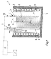
- Fig. 1 shows a beverage dispenser 1 with a beverage 2 and a container 12 which is filled with a heat transfer medium 4.
- the heat transfer medium 4 may be a coolant, in particular water, air or a saline solution.
- Via a supply line 13 the beverage 2 is passed into a heat exchanger 3.
- the supply line 13 is connected to a reservoir, not shown here. From the heat exchanger 3, the beverage 2 is guided via a discharge line 14 to a dispensing valve, not shown.
- the heat exchanger 3 is formed in a spiral shape. In this case, it surrounds a circulation device 6.
- the circulation device 6, which may have, for example, a stirrer, ensures a homogeneous temperature distribution in the container 12.
- Fig. 1 is indicated by two arrows as the heat transfer medium 4 is moved by the circulation device 6.
- the heat transfer medium 4 is not only connected to the heat exchanger 3 in connection, but in addition to a further heat exchanger 8.
- the further heat exchanger 8 may be formed as a cooling device. In Fig. 1 the further heat exchanger is shown as a line spiral. On a contact surface of the further heat exchanger 8 with the heat transfer medium 4, a solid portion 9 of the heat carrier 4 can form. If water is used as the heat carrier 4, an ice layer will form.
- the solids content 9 then serves as a heat / cold reservoir for the heat transfer medium 4.
- the solids content 9 should never be 100% of the heat transfer medium 4, since otherwise damage to one of the components of the beverage discharge device could occur.
- a heat capacity of the heat carrier 4 can be measured by a heat receiving ability sensor 10 become.
- the heat-absorbing capacity sensor 10 can be embodied as at least one ultrasonic sensor, or as at least one conductivity sensor, or as at least one pressure sensor, or as at least one laser sensor or as at least one thermal sensor. In this case, the heat-absorbing capacity sensor 10 can measure the solids content 9 of the heat carrier 4.
- thermal sensor not only a thermal sensor but also an entire array of thermal sensors can be provided.
- a part of this field can be surrounded by the solid state portion 9, while a part of the field is in a non-solid part of the heat carrier. Due to the relative proportion of heat sensors, which are arranged in the solid state portion 9, one can thus determine the solids content 9.
- a beverage flow sensor 11 is provided, which in Fig. 1 is arranged in the inlet and outlet 13 and 14.
- beverage flow sensor 11 a plurality of sensors is conceivable. For example, with a heat sensor or a rotary wheel, beverage flow can be measured.
- the size of the beverage flow and the heat capacity are then transmitted to a control unit 5.
- the control unit 5 then controls an aggregate 6 or 7.
- the aggregate 6 or 7 may be, for example, the circulation device 6 or a display 7.
- the display may be, for example, a lamp or a complex electronic display panel. But it is also possible that the power of the further heat exchanger 8 is changed by a flow in the other heat exchanger 8 is adjusted. But it is also conceivable a variety of other devices that are operated by the control unit in dependence on the beverage flow and the heat capacity. External devices that are in operative connection with the dispenser are conceivable.
- the beverage 2 When the dispensing valve is opened, the beverage 2 is conveyed from the reservoir through the supply line 13, through the heat exchanger 3 and the discharge line 14 to the dispensing valve.
- the beverage 2 is brought in the heat exchanger 3 to the desired temperature.
- the heat exchanger 3 in turn is in the heat exchange in the heat transfer medium 4.
- the heat absorption capacity of the heat carrier 4 is also determined by the temperature and the state of aggregation.
- the desired heat capacity is controlled by the control unit 5, the further heat exchanger 8 controls, and so the temperature and the solids content 9 of the heat carrier 6 sets.
- control unit 5 can be done by the control unit 5 so that only the desired heat capacity of the heat carrier is always set, which is at least necessary to obtain the desired temperature of the beverage.
- control unit 5 uses the size of the beverage flow rate and the heat absorption capacity and then controls the further heat exchanger 8. In this way, energy can be saved in the beverage dispenser.
- the control unit can also drive a variety of other devices to reduce their energy consumption.
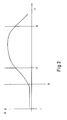
- Fig. 2 the beverage flow A is shown as a function of time t.
- the flow A is low and the control unit 5 controls the heat absorption capacity so that only a small solid fraction 9 is formed.
- the beverage flow is medium, so that a medium-sized solid content is formed.
- the flow and the solids content is finally maximum.
- the flow is again medium-sized and thus also the solids content.
Landscapes
- Engineering & Computer Science (AREA)
- Physics & Mathematics (AREA)
- Thermal Sciences (AREA)
- Chemical & Material Sciences (AREA)
- Combustion & Propulsion (AREA)
- Mechanical Engineering (AREA)
- General Engineering & Computer Science (AREA)
- Devices That Are Associated With Refrigeration Equipment (AREA)
- Filling Of Jars Or Cans And Processes For Cleaning And Sealing Jars (AREA)
- Apparatus For Making Beverages (AREA)
Applications Claiming Priority (2)
| Application Number | Priority Date | Filing Date | Title |
|---|---|---|---|
| DE200910007654 DE102009007654B4 (de) | 2009-02-05 | 2009-02-05 | Energieeffiziente Getränkeabgabeeinrichtung und Verfahren zur energieeffizienten Getränkeabgabe |
| PCT/EP2010/000681 WO2010089108A1 (de) | 2009-02-05 | 2010-02-04 | Energieeffiziente getränkeabgabeeinrichtung und verfahren zur energieeffizienten getränkabgabe |
Publications (2)
| Publication Number | Publication Date |
|---|---|
| EP2393749A1 EP2393749A1 (de) | 2011-12-14 |
| EP2393749B1 true EP2393749B1 (de) | 2013-05-01 |
Family
ID=42126439
Family Applications (1)
| Application Number | Title | Priority Date | Filing Date |
|---|---|---|---|
| EP10710183.4A Not-in-force EP2393749B1 (de) | 2009-02-05 | 2010-02-04 | Energieeffiziente getränkeabgabeeinrichtung und verfahren zur energieeffizienten getränkabgabe |
Country Status (5)
| Country | Link |
|---|---|
| EP (1) | EP2393749B1 (ru) |
| DE (1) | DE102009007654B4 (ru) |
| EA (1) | EA201101170A1 (ru) |
| UA (1) | UA101092C2 (ru) |
| WO (1) | WO2010089108A1 (ru) |
Families Citing this family (2)
| Publication number | Priority date | Publication date | Assignee | Title |
|---|---|---|---|---|
| GB2529222B (en) | 2014-08-14 | 2021-06-30 | Heineken Uk Ltd | Beverage dispense systems |
| JP6916488B2 (ja) | 2017-12-11 | 2021-08-11 | アサヒビール株式会社 | 液体品質管理装置 |
Family Cites Families (5)
| Publication number | Priority date | Publication date | Assignee | Title |
|---|---|---|---|---|
| US4939908A (en) * | 1987-05-15 | 1990-07-10 | Ewing Leonard G | Apparatus for adjustably controlling the size of an ice bank |
| JP2000207631A (ja) * | 1999-01-13 | 2000-07-28 | Sanyo Electric Co Ltd | 飲料供給装置 |
| JP4288550B2 (ja) * | 2000-06-16 | 2009-07-01 | 富士電機リテイルシステムズ株式会社 | 蓄氷式飲料冷却装置の運転方法 |
| JP2002203275A (ja) * | 2000-12-28 | 2002-07-19 | Fuji Electric Co Ltd | 蓄氷式飲料冷却装置の運転制御方法 |
| US6662573B2 (en) * | 2002-04-30 | 2003-12-16 | Lancer Partnership, Ltd. | Cooling bank control assembly for a beverage dispensing system |
-
2009
- 2009-02-05 DE DE200910007654 patent/DE102009007654B4/de not_active Expired - Fee Related
-
2010
- 2010-02-04 WO PCT/EP2010/000681 patent/WO2010089108A1/de active Application Filing
- 2010-02-04 EA EA201101170A patent/EA201101170A1/ru unknown
- 2010-02-04 UA UAA201110705A patent/UA101092C2/ru unknown
- 2010-02-04 EP EP10710183.4A patent/EP2393749B1/de not_active Not-in-force
Also Published As
| Publication number | Publication date |
|---|---|
| UA101092C2 (ru) | 2013-02-25 |
| DE102009007654B4 (de) | 2013-05-16 |
| WO2010089108A1 (de) | 2010-08-12 |
| EP2393749A1 (de) | 2011-12-14 |
| EA201101170A1 (ru) | 2012-02-28 |
| DE102009007654A1 (de) | 2010-11-11 |
Similar Documents
| Publication | Publication Date | Title |
|---|---|---|
| DE60020429T2 (de) | Wärmeaustauschsystem mit geschlossenem Kreislauf und Verfahren mit niedrigem Wasserverbrauch | |
| EP2331880B1 (de) | Verfahren und vorrichtung zur bereitstellung nutzbarer wärmeenergie | |
| EP3355717B1 (de) | Anlage und verfahren für die pasteurisierung von lebensmitteln | |
| DE2900372C2 (ru) | ||
| AT411890B (de) | Verfahren zum beheizen und kühlen von extruderzylindern sowie vorrichtung hierfür | |
| EP3607249B1 (de) | Wärmepumpenanlage | |
| EP2963350A1 (de) | System zum energiesparenden betrieb nicht permanent genutzter oder nicht permanent ausgelasteter wärmetauscher in einem leitungssystem, insbesondere zur trinkwassererwärmung | |
| EP2393749B1 (de) | Energieeffiziente getränkeabgabeeinrichtung und verfahren zur energieeffizienten getränkabgabe | |
| DE102012101271C5 (de) | Kühleinrichtung | |
| EP3619483B1 (de) | Kühlmöbel mit speicher, kühlsystem und verfahren zum steuern eines kühlmöbels mit einem speicher | |
| DE102008057495A1 (de) | Wärmespeicheranordnung | |
| DE102015117948B4 (de) | Kältespeicher und Kühlsystem | |
| EP3076111B1 (de) | Fluidsystem und verfahren zum steuern eines fluidsystems | |
| EP1092926A2 (de) | System zum Erwärmen von Zapfwasser mit Sonnenenergie, mit Anti-Legionella-Einrichtungen | |
| DE60223941T2 (de) | Abluftwärmepumpe | |
| EP2126486B1 (de) | Kältegerät | |
| WO2002012814A1 (de) | Latentwärmespeicher | |
| EP3587968B1 (de) | Fluidsystem | |
| DE102009024305B4 (de) | Wärmepumpenheizung mit mehrteiligem Kondensator | |
| DE102009024355A1 (de) | Solar-Heizungssystem | |
| DE10024547A1 (de) | Verfahren und Vorrichtung zur biologischen Reinigung von Substraten mittels Wärmenutzung | |
| DE102006056979B4 (de) | Vorrichtung zur Wärmegewinnung | |
| EP2095042B1 (de) | Kühlgerät mit einem magnetischen kühler | |
| AT514844B1 (de) | Plattenförmiger Wärmetauscher und Verfahren zum Betreiben des Wärmetauschers | |
| CH670298A5 (ru) |
Legal Events
| Date | Code | Title | Description |
|---|---|---|---|
| PUAI | Public reference made under article 153(3) epc to a published international application that has entered the european phase |
Free format text: ORIGINAL CODE: 0009012 |
|
| 17P | Request for examination filed |
Effective date: 20110902 |
|
| AK | Designated contracting states |
Kind code of ref document: A1 Designated state(s): AT BE BG CH CY CZ DE DK EE ES FI FR GB GR HR HU IE IS IT LI LT LU LV MC MK MT NL NO PL PT RO SE SI SK SM TR |
|
| DAX | Request for extension of the european patent (deleted) | ||
| GRAP | Despatch of communication of intention to grant a patent |
Free format text: ORIGINAL CODE: EPIDOSNIGR1 |
|
| GRAS | Grant fee paid |
Free format text: ORIGINAL CODE: EPIDOSNIGR3 |
|
| GRAA | (expected) grant |
Free format text: ORIGINAL CODE: 0009210 |
|
| AK | Designated contracting states |
Kind code of ref document: B1 Designated state(s): AT BE BG CH CY CZ DE DK EE ES FI FR GB GR HR HU IE IS IT LI LT LU LV MC MK MT NL NO PL PT RO SE SI SK SM TR |
|
| REG | Reference to a national code |
Ref country code: GB Ref legal event code: FG4D Free format text: NOT ENGLISH |
|
| REG | Reference to a national code |
Ref country code: AT Ref legal event code: REF Ref document number: 609834 Country of ref document: AT Kind code of ref document: T Effective date: 20130515 Ref country code: CH Ref legal event code: EP |
|
| REG | Reference to a national code |
Ref country code: IE Ref legal event code: FG4D Free format text: LANGUAGE OF EP DOCUMENT: GERMAN |
|
| REG | Reference to a national code |
Ref country code: DE Ref legal event code: R096 Ref document number: 502010003161 Country of ref document: DE Effective date: 20130627 |
|
| REG | Reference to a national code |
Ref country code: NL Ref legal event code: VDEP Effective date: 20130501 |
|
| REG | Reference to a national code |
Ref country code: LT Ref legal event code: MG4D |
|
| PG25 | Lapsed in a contracting state [announced via postgrant information from national office to epo] |
Ref country code: SI Free format text: LAPSE BECAUSE OF FAILURE TO SUBMIT A TRANSLATION OF THE DESCRIPTION OR TO PAY THE FEE WITHIN THE PRESCRIBED TIME-LIMIT Effective date: 20130501 Ref country code: SE Free format text: LAPSE BECAUSE OF FAILURE TO SUBMIT A TRANSLATION OF THE DESCRIPTION OR TO PAY THE FEE WITHIN THE PRESCRIBED TIME-LIMIT Effective date: 20130501 Ref country code: FI Free format text: LAPSE BECAUSE OF FAILURE TO SUBMIT A TRANSLATION OF THE DESCRIPTION OR TO PAY THE FEE WITHIN THE PRESCRIBED TIME-LIMIT Effective date: 20130501 Ref country code: PT Free format text: LAPSE BECAUSE OF FAILURE TO SUBMIT A TRANSLATION OF THE DESCRIPTION OR TO PAY THE FEE WITHIN THE PRESCRIBED TIME-LIMIT Effective date: 20130902 Ref country code: GR Free format text: LAPSE BECAUSE OF FAILURE TO SUBMIT A TRANSLATION OF THE DESCRIPTION OR TO PAY THE FEE WITHIN THE PRESCRIBED TIME-LIMIT Effective date: 20130802 Ref country code: LT Free format text: LAPSE BECAUSE OF FAILURE TO SUBMIT A TRANSLATION OF THE DESCRIPTION OR TO PAY THE FEE WITHIN THE PRESCRIBED TIME-LIMIT Effective date: 20130501 Ref country code: ES Free format text: LAPSE BECAUSE OF FAILURE TO SUBMIT A TRANSLATION OF THE DESCRIPTION OR TO PAY THE FEE WITHIN THE PRESCRIBED TIME-LIMIT Effective date: 20130812 Ref country code: NO Free format text: LAPSE BECAUSE OF FAILURE TO SUBMIT A TRANSLATION OF THE DESCRIPTION OR TO PAY THE FEE WITHIN THE PRESCRIBED TIME-LIMIT Effective date: 20130801 Ref country code: IS Free format text: LAPSE BECAUSE OF FAILURE TO SUBMIT A TRANSLATION OF THE DESCRIPTION OR TO PAY THE FEE WITHIN THE PRESCRIBED TIME-LIMIT Effective date: 20130901 |
|
| PG25 | Lapsed in a contracting state [announced via postgrant information from national office to epo] |
Ref country code: BG Free format text: LAPSE BECAUSE OF FAILURE TO SUBMIT A TRANSLATION OF THE DESCRIPTION OR TO PAY THE FEE WITHIN THE PRESCRIBED TIME-LIMIT Effective date: 20130801 Ref country code: HR Free format text: LAPSE BECAUSE OF FAILURE TO SUBMIT A TRANSLATION OF THE DESCRIPTION OR TO PAY THE FEE WITHIN THE PRESCRIBED TIME-LIMIT Effective date: 20130501 Ref country code: PL Free format text: LAPSE BECAUSE OF FAILURE TO SUBMIT A TRANSLATION OF THE DESCRIPTION OR TO PAY THE FEE WITHIN THE PRESCRIBED TIME-LIMIT Effective date: 20130501 Ref country code: CY Free format text: LAPSE BECAUSE OF FAILURE TO SUBMIT A TRANSLATION OF THE DESCRIPTION OR TO PAY THE FEE WITHIN THE PRESCRIBED TIME-LIMIT Effective date: 20130501 |
|
| PG25 | Lapsed in a contracting state [announced via postgrant information from national office to epo] |
Ref country code: LV Free format text: LAPSE BECAUSE OF FAILURE TO SUBMIT A TRANSLATION OF THE DESCRIPTION OR TO PAY THE FEE WITHIN THE PRESCRIBED TIME-LIMIT Effective date: 20130501 |
|
| PG25 | Lapsed in a contracting state [announced via postgrant information from national office to epo] |
Ref country code: EE Free format text: LAPSE BECAUSE OF FAILURE TO SUBMIT A TRANSLATION OF THE DESCRIPTION OR TO PAY THE FEE WITHIN THE PRESCRIBED TIME-LIMIT Effective date: 20130501 Ref country code: CZ Free format text: LAPSE BECAUSE OF FAILURE TO SUBMIT A TRANSLATION OF THE DESCRIPTION OR TO PAY THE FEE WITHIN THE PRESCRIBED TIME-LIMIT Effective date: 20130501 Ref country code: SK Free format text: LAPSE BECAUSE OF FAILURE TO SUBMIT A TRANSLATION OF THE DESCRIPTION OR TO PAY THE FEE WITHIN THE PRESCRIBED TIME-LIMIT Effective date: 20130501 Ref country code: DK Free format text: LAPSE BECAUSE OF FAILURE TO SUBMIT A TRANSLATION OF THE DESCRIPTION OR TO PAY THE FEE WITHIN THE PRESCRIBED TIME-LIMIT Effective date: 20130501 |
|
| PG25 | Lapsed in a contracting state [announced via postgrant information from national office to epo] |
Ref country code: RO Free format text: LAPSE BECAUSE OF FAILURE TO SUBMIT A TRANSLATION OF THE DESCRIPTION OR TO PAY THE FEE WITHIN THE PRESCRIBED TIME-LIMIT Effective date: 20130501 Ref country code: NL Free format text: LAPSE BECAUSE OF FAILURE TO SUBMIT A TRANSLATION OF THE DESCRIPTION OR TO PAY THE FEE WITHIN THE PRESCRIBED TIME-LIMIT Effective date: 20130501 |
|
| PLBE | No opposition filed within time limit |
Free format text: ORIGINAL CODE: 0009261 |
|
| STAA | Information on the status of an ep patent application or granted ep patent |
Free format text: STATUS: NO OPPOSITION FILED WITHIN TIME LIMIT |
|
| 26N | No opposition filed |
Effective date: 20140204 |
|
| REG | Reference to a national code |
Ref country code: DE Ref legal event code: R097 Ref document number: 502010003161 Country of ref document: DE Effective date: 20140204 |
|
| BERE | Be: lapsed |
Owner name: DANFOSS A/S Effective date: 20140228 |
|
| REG | Reference to a national code |
Ref country code: DE Ref legal event code: R119 Ref document number: 502010003161 Country of ref document: DE |
|
| PG25 | Lapsed in a contracting state [announced via postgrant information from national office to epo] |
Ref country code: LU Free format text: LAPSE BECAUSE OF FAILURE TO SUBMIT A TRANSLATION OF THE DESCRIPTION OR TO PAY THE FEE WITHIN THE PRESCRIBED TIME-LIMIT Effective date: 20140204 Ref country code: MC Free format text: LAPSE BECAUSE OF FAILURE TO SUBMIT A TRANSLATION OF THE DESCRIPTION OR TO PAY THE FEE WITHIN THE PRESCRIBED TIME-LIMIT Effective date: 20130501 |
|
| REG | Reference to a national code |
Ref country code: CH Ref legal event code: PL |
|
| GBPC | Gb: european patent ceased through non-payment of renewal fee |
Effective date: 20140204 |
|
| PG25 | Lapsed in a contracting state [announced via postgrant information from national office to epo] |
Ref country code: LI Free format text: LAPSE BECAUSE OF NON-PAYMENT OF DUE FEES Effective date: 20140228 Ref country code: CH Free format text: LAPSE BECAUSE OF NON-PAYMENT OF DUE FEES Effective date: 20140228 |
|
| REG | Reference to a national code |
Ref country code: DE Ref legal event code: R119 Ref document number: 502010003161 Country of ref document: DE Effective date: 20140902 |
|
| REG | Reference to a national code |
Ref country code: FR Ref legal event code: ST Effective date: 20141031 |
|
| REG | Reference to a national code |
Ref country code: IE Ref legal event code: MM4A |
|
| PG25 | Lapsed in a contracting state [announced via postgrant information from national office to epo] |
Ref country code: FR Free format text: LAPSE BECAUSE OF NON-PAYMENT OF DUE FEES Effective date: 20140228 Ref country code: IE Free format text: LAPSE BECAUSE OF NON-PAYMENT OF DUE FEES Effective date: 20140204 Ref country code: GB Free format text: LAPSE BECAUSE OF NON-PAYMENT OF DUE FEES Effective date: 20140204 Ref country code: BE Free format text: LAPSE BECAUSE OF NON-PAYMENT OF DUE FEES Effective date: 20140228 Ref country code: DE Free format text: LAPSE BECAUSE OF NON-PAYMENT OF DUE FEES Effective date: 20140902 |
|
| PG25 | Lapsed in a contracting state [announced via postgrant information from national office to epo] |
Ref country code: MT Free format text: LAPSE BECAUSE OF FAILURE TO SUBMIT A TRANSLATION OF THE DESCRIPTION OR TO PAY THE FEE WITHIN THE PRESCRIBED TIME-LIMIT Effective date: 20130501 |
|
| REG | Reference to a national code |
Ref country code: AT Ref legal event code: MM01 Ref document number: 609834 Country of ref document: AT Kind code of ref document: T Effective date: 20150204 |
|
| PG25 | Lapsed in a contracting state [announced via postgrant information from national office to epo] |
Ref country code: SM Free format text: LAPSE BECAUSE OF FAILURE TO SUBMIT A TRANSLATION OF THE DESCRIPTION OR TO PAY THE FEE WITHIN THE PRESCRIBED TIME-LIMIT Effective date: 20130501 |
|
| PG25 | Lapsed in a contracting state [announced via postgrant information from national office to epo] |
Ref country code: AT Free format text: LAPSE BECAUSE OF NON-PAYMENT OF DUE FEES Effective date: 20150204 |
|
| PG25 | Lapsed in a contracting state [announced via postgrant information from national office to epo] |
Ref country code: IT Free format text: LAPSE BECAUSE OF NON-PAYMENT OF DUE FEES Effective date: 20140204 |
|
| PG25 | Lapsed in a contracting state [announced via postgrant information from national office to epo] |
Ref country code: HU Free format text: LAPSE BECAUSE OF FAILURE TO SUBMIT A TRANSLATION OF THE DESCRIPTION OR TO PAY THE FEE WITHIN THE PRESCRIBED TIME-LIMIT; INVALID AB INITIO Effective date: 20100204 Ref country code: TR Free format text: LAPSE BECAUSE OF FAILURE TO SUBMIT A TRANSLATION OF THE DESCRIPTION OR TO PAY THE FEE WITHIN THE PRESCRIBED TIME-LIMIT Effective date: 20130501 |
|
| PG25 | Lapsed in a contracting state [announced via postgrant information from national office to epo] |
Ref country code: MK Free format text: LAPSE BECAUSE OF FAILURE TO SUBMIT A TRANSLATION OF THE DESCRIPTION OR TO PAY THE FEE WITHIN THE PRESCRIBED TIME-LIMIT Effective date: 20130501 |