EP2392284B1 - Kennzeichnungssystem für medizinische Implantate - Google Patents
Kennzeichnungssystem für medizinische Implantate Download PDFInfo
- Publication number
- EP2392284B1 EP2392284B1 EP11004528.3A EP11004528A EP2392284B1 EP 2392284 B1 EP2392284 B1 EP 2392284B1 EP 11004528 A EP11004528 A EP 11004528A EP 2392284 B1 EP2392284 B1 EP 2392284B1
- Authority
- EP
- European Patent Office
- Prior art keywords
- data carrier
- implant
- data
- receiving
- magazine
- Prior art date
- Legal status (The legal status is an assumption and is not a legal conclusion. Google has not performed a legal analysis and makes no representation as to the accuracy of the status listed.)
- Not-in-force
Links
- 239000007943 implant Substances 0.000 title claims description 105
- 239000000969 carrier Substances 0.000 claims description 12
- 239000000853 adhesive Substances 0.000 claims description 2
- 230000001070 adhesive effect Effects 0.000 claims description 2
- 239000007769 metal material Substances 0.000 claims 1
- 230000002035 prolonged effect Effects 0.000 claims 1
- 238000002372 labelling Methods 0.000 description 28
- 210000000988 bone and bone Anatomy 0.000 description 9
- 230000005540 biological transmission Effects 0.000 description 5
- 210000003625 skull Anatomy 0.000 description 5
- 230000001954 sterilising effect Effects 0.000 description 4
- 238000003780 insertion Methods 0.000 description 3
- 230000037431 insertion Effects 0.000 description 3
- 238000000926 separation method Methods 0.000 description 3
- 238000004659 sterilization and disinfection Methods 0.000 description 3
- 238000003466 welding Methods 0.000 description 3
- 238000010276 construction Methods 0.000 description 2
- 239000003292 glue Substances 0.000 description 2
- NJPPVKZQTLUDBO-UHFFFAOYSA-N novaluron Chemical compound C1=C(Cl)C(OC(F)(F)C(OC(F)(F)F)F)=CC=C1NC(=O)NC(=O)C1=C(F)C=CC=C1F NJPPVKZQTLUDBO-UHFFFAOYSA-N 0.000 description 2
- 238000004026 adhesive bonding Methods 0.000 description 1
- 239000002390 adhesive tape Substances 0.000 description 1
- 239000003795 chemical substances by application Substances 0.000 description 1
- 230000000881 depressing effect Effects 0.000 description 1
- 239000000463 material Substances 0.000 description 1
- 239000011159 matrix material Substances 0.000 description 1
- 238000004806 packaging method and process Methods 0.000 description 1
- 239000000123 paper Substances 0.000 description 1
- 239000000047 product Substances 0.000 description 1
- 239000006228 supernatant Substances 0.000 description 1
- 238000013518 transcription Methods 0.000 description 1
- 230000035897 transcription Effects 0.000 description 1
Images

Classifications
-
- G—PHYSICS
- G09—EDUCATION; CRYPTOGRAPHY; DISPLAY; ADVERTISING; SEALS
- G09F—DISPLAYING; ADVERTISING; SIGNS; LABELS OR NAME-PLATES; SEALS
- G09F3/00—Labels, tag tickets, or similar identification or indication means; Seals; Postage or like stamps
- G09F3/04—Labels, tag tickets, or similar identification or indication means; Seals; Postage or like stamps to be fastened or secured by the material of the label itself, e.g. by thermo-adhesion
-
- A—HUMAN NECESSITIES
- A61—MEDICAL OR VETERINARY SCIENCE; HYGIENE
- A61B—DIAGNOSIS; SURGERY; IDENTIFICATION
- A61B50/00—Containers, covers, furniture or holders specially adapted for surgical or diagnostic appliances or instruments, e.g. sterile covers
- A61B50/20—Holders specially adapted for surgical or diagnostic appliances or instruments
-
- A—HUMAN NECESSITIES
- A61—MEDICAL OR VETERINARY SCIENCE; HYGIENE
- A61B—DIAGNOSIS; SURGERY; IDENTIFICATION
- A61B50/00—Containers, covers, furniture or holders specially adapted for surgical or diagnostic appliances or instruments, e.g. sterile covers
- A61B50/30—Containers specially adapted for packaging, protecting, dispensing, collecting or disposing of surgical or diagnostic appliances or instruments
-
- A—HUMAN NECESSITIES
- A61—MEDICAL OR VETERINARY SCIENCE; HYGIENE
- A61B—DIAGNOSIS; SURGERY; IDENTIFICATION
- A61B90/00—Instruments, implements or accessories specially adapted for surgery or diagnosis and not covered by any of the groups A61B1/00 - A61B50/00, e.g. for luxation treatment or for protecting wound edges
- A61B90/90—Identification means for patients or instruments, e.g. tags
- A61B90/94—Identification means for patients or instruments, e.g. tags coded with symbols, e.g. text
-
- A—HUMAN NECESSITIES
- A61—MEDICAL OR VETERINARY SCIENCE; HYGIENE
- A61B—DIAGNOSIS; SURGERY; IDENTIFICATION
- A61B17/00—Surgical instruments, devices or methods
- A61B17/56—Surgical instruments or methods for treatment of bones or joints; Devices specially adapted therefor
- A61B17/58—Surgical instruments or methods for treatment of bones or joints; Devices specially adapted therefor for osteosynthesis, e.g. bone plates, screws or setting implements
- A61B17/68—Internal fixation devices, including fasteners and spinal fixators, even if a part thereof projects from the skin
- A61B17/84—Fasteners therefor or fasteners being internal fixation devices
- A61B17/86—Pins or screws or threaded wires; nuts therefor
- A61B17/865—Packages or dispensers for bone screws or threaded wires
-
- A—HUMAN NECESSITIES
- A61—MEDICAL OR VETERINARY SCIENCE; HYGIENE
- A61B—DIAGNOSIS; SURGERY; IDENTIFICATION
- A61B90/00—Instruments, implements or accessories specially adapted for surgery or diagnosis and not covered by any of the groups A61B1/00 - A61B50/00, e.g. for luxation treatment or for protecting wound edges
- A61B90/03—Automatic limiting or abutting means, e.g. for safety
- A61B2090/037—Automatic limiting or abutting means, e.g. for safety with a frangible part, e.g. by reduced diameter
-
- A—HUMAN NECESSITIES
- A61—MEDICAL OR VETERINARY SCIENCE; HYGIENE
- A61F—FILTERS IMPLANTABLE INTO BLOOD VESSELS; PROSTHESES; DEVICES PROVIDING PATENCY TO, OR PREVENTING COLLAPSING OF, TUBULAR STRUCTURES OF THE BODY, e.g. STENTS; ORTHOPAEDIC, NURSING OR CONTRACEPTIVE DEVICES; FOMENTATION; TREATMENT OR PROTECTION OF EYES OR EARS; BANDAGES, DRESSINGS OR ABSORBENT PADS; FIRST-AID KITS
- A61F2/00—Filters implantable into blood vessels; Prostheses, i.e. artificial substitutes or replacements for parts of the body; Appliances for connecting them with the body; Devices providing patency to, or preventing collapsing of, tubular structures of the body, e.g. stents
- A61F2/02—Prostheses implantable into the body
- A61F2/30—Joints
- A61F2002/30001—Additional features of subject-matter classified in A61F2/28, A61F2/30 and subgroups thereof
- A61F2002/30667—Features concerning an interaction with the environment or a particular use of the prosthesis
- A61F2002/3071—Identification means; Administration of patients
-
- A—HUMAN NECESSITIES
- A61—MEDICAL OR VETERINARY SCIENCE; HYGIENE
- A61F—FILTERS IMPLANTABLE INTO BLOOD VESSELS; PROSTHESES; DEVICES PROVIDING PATENCY TO, OR PREVENTING COLLAPSING OF, TUBULAR STRUCTURES OF THE BODY, e.g. STENTS; ORTHOPAEDIC, NURSING OR CONTRACEPTIVE DEVICES; FOMENTATION; TREATMENT OR PROTECTION OF EYES OR EARS; BANDAGES, DRESSINGS OR ABSORBENT PADS; FIRST-AID KITS
- A61F2250/00—Special features of prostheses classified in groups A61F2/00 - A61F2/26 or A61F2/82 or A61F9/00 or A61F11/00 or subgroups thereof
- A61F2250/0058—Additional features; Implant or prostheses properties not otherwise provided for
- A61F2250/0085—Identification means; Administration of patients
-
- A—HUMAN NECESSITIES
- A61—MEDICAL OR VETERINARY SCIENCE; HYGIENE
- A61F—FILTERS IMPLANTABLE INTO BLOOD VESSELS; PROSTHESES; DEVICES PROVIDING PATENCY TO, OR PREVENTING COLLAPSING OF, TUBULAR STRUCTURES OF THE BODY, e.g. STENTS; ORTHOPAEDIC, NURSING OR CONTRACEPTIVE DEVICES; FOMENTATION; TREATMENT OR PROTECTION OF EYES OR EARS; BANDAGES, DRESSINGS OR ABSORBENT PADS; FIRST-AID KITS
- A61F2250/00—Special features of prostheses classified in groups A61F2/00 - A61F2/26 or A61F2/82 or A61F9/00 or A61F11/00 or subgroups thereof
- A61F2250/0058—Additional features; Implant or prostheses properties not otherwise provided for
- A61F2250/0085—Identification means; Administration of patients
- A61F2250/0089—Identification means; Administration of patients coded with symbols, e.g. dots, numbers, letters, words
-
- G—PHYSICS
- G09—EDUCATION; CRYPTOGRAPHY; DISPLAY; ADVERTISING; SEALS
- G09F—DISPLAYING; ADVERTISING; SIGNS; LABELS OR NAME-PLATES; SEALS
- G09F7/00—Signs, name or number plates, letters, numerals, or symbols; Panels or boards
- G09F7/18—Means for attaching signs, plates, panels, or boards to a supporting structure
- G09F2007/1856—Means for attaching signs, plates, panels, or boards to a supporting structure characterised by the supporting structure
- G09F2007/1869—Means for attaching signs, plates, panels, or boards to a supporting structure characterised by the supporting structure plates fixed to instruments
Definitions
- the invention relates to a labeling system for medical implants, in which product-specific data such as, for. B. manufacturer, batch or other identification data are indelibly applied, by means of which the origin or the properties or the origin and the properties of the implant concerned are traceable, wherein the labeling surface is located on a disk having the shape of a small plate, label or strip ,
- the identification data of an implant are attached directly to the implant itself and / or on the packaging.
- a holding device for receiving bone screws in which implant data are arranged on a visible surface.
- This holding device has a base body, in which the implant is releasably inserted via a type latching or clamping connection.
- Several such holding devices can be detachably inserted together with the implant received in a storage unit, for which purpose the holding device is provided in each case with further locking elements.
- the holding device is first removed from the storage unit. Subsequently, the implant is removed from the holding device and inserted into the body of the patient.
- the implant Because the implant is no longer accessible after insertion into the body of the patient and the holding device can not be archived due to its dimensions, the data for archiving and assignment to the respective patient must be written off from the holding device and transferred to the patient file. This transmission errors may arise, so that a reliable traceability is not guaranteed with the required security.
- the data carrier is provided with a leaf spring-like actuating element, which has a central, protruding from the plane of the data carrier actuating portion.
- the free, resiliently movable end region of the actuating element is arranged "below" the plane of the data carrier and has on the upper side a retaining pin, which can be inserted into one of the bores of the bone plate.
- U-legs On both sides of the actuating element U-legs are provided which extend laterally into the region of the retaining pin and serve with their end portions as on the bone plate upper side attachable abutment in the region of the retaining pin.
- bearing element is provided, on which two the disk are formed.
- One of the data carriers runs on the underside parallel to the axis of a male bone screw, while the second data carrier is designed as an upper side laterally projecting element.
- This bearing element 5 is associated with a receiving element 3, which is insertable into the bearing element and which receives the bone screw. If this receiving element is located in the bearing element in a starting position, then the bone screw is secured in a latching manner in the receiving element as well as in the bearing element by a retaining clip. By depressing the receiving element relative to the bearing element of the headband is in the in the Fig.
- the invention is accordingly an object of the invention to provide an identification system of the type mentioned, in which an implant is easily and safely receivable and in which the data of the implant used in the specified by the manufacturer of the implant form and completeness are recorded in the patient record, to avoid transmission errors.
- the object is achieved according to the invention together with the features of the preamble of claim 1, characterized in that the disk is manually detachably connected to the implant receiving bearing element and the implant is captively secured in the bearing element by the disk and that the separated disk on or on a Patient document by means of a glue or a staple connection captive fastened.
- a data carrier in the form of a thin plate, tag or strip can be easily attached to a patient document made of paper or lightweight cardboard, for example by gluing or by means of staples, and stored together with the latter for archiving purposes.
- a particular advantage also lies in the fact that the marking system according to the invention can be used equally well for plate-shaped implants as well as for implants in the form of implant screws.
- a receiving magazine or a data carrier magazine can be provided for the storage of several receiving sleeves or implant screws, which has a plurality of receiving bores or through holes for receiving the receiving sleeves or provided with a data carrier implant screws.
- the connecting portion of the receiving sleeve is located on an end face of the receiving sleeve and that the connecting portion has a cross-sectional taper created by a notch-like depression.
- the data carrier is easily accessible on the one end face of the receiving sleeve and can also be easily separated manually by the notch-like depression of the connecting section.
- the arrangement of the connecting portion and thus also of the data carrier also facilitates clarity and thus improves handling.
- the data carrier magazine consists of at least one row of through holes for implant screws having elongate block in which the through holes are covered on the upper side by individual, separately detachable, the implant located in the holes implant screws disk whose Connection sections are on the upper side outside the holes.
- the data carrier and the part with which it is torn off can be made of plastic.
- the connecting portion may be formed as a film hinge.
- each hole of the existing plastic data carrier magazine is assigned to its cover a cover formed as a disk, which is hinged by means of a film hinge on a longitudinal edge of the data carrier magazine forming block hinged and torn off.
- This embodiment is extremely advantageous for the storage of several implant screws in a common data carrier magazine.
- the designed as a lid data carrier on a film hinge on the data carrier magazine opening the lid (or the lid) for loading the data carrier magazine in just as simple manner as feasible as the final removal of the disk.
- the designed as a swiveling cover disk of the data carrier magazine are each fixed by means of a arranged on the end face of the data carrier magazine locking tab in its closed position, wherein the locking tab overlaps the respective associated disk with a latching lug.
- the identification sleeve has an axially extended pedestal with a bottom-side, essentially flat, approximately annular base.
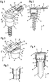
- Fig. 1 shows a perspective view of a first embodiment of an identification system 1, which serves to receive an implant designed as an implant screw 2 implant.
- This identification system 1 consists of a receiving sleeve 3, which forms a downwardly radially tapered plug-in sleeve 4.
- a radially enlarged head part 5 is placed on the socket 4, which is integral with the socket 4 in conjunction.
- this receiving sleeve 3 has a multiple stepped through hole 6, which is provided in the region of the head part 5 with a radially enlarged bore portion 7.
- This bore section 7 serves to receive a screw head 8 of the implant screw 2 Fig. 2
- the screw head 8 is supported in the through hole 6 at a radially inwardly projecting support web 9 axially, so that the implant screw 2 is secured against falling out of the receiving sleeve 3 in the direction of the arrow 10.
- Fig. 1 and 2 can be seen that the receiving sleeve 3 in the vicinity of the radially enlarged bore portion 7 has a vertically over the upper annular surface 11 of the head part 5 upwardly projecting retaining web 12.
- an approximately platelet-shaped data carrier 13 is placed, which is held on the top of the retaining web 12, for example by an adhesive or welded connection.
- the data carrier 13 in the region of the holding web 12 on the upper side with a transverse notch 14 is provided so that in this region of the notch 14 a film hinge-like trained connecting portion 15 between the attached to the support web 12 and fixedly connected thereto holding portion 16 of the data carrier 13 and a plate-shaped laterally over the head part 5 of the receiving sleeve. 3 above data carrier section 17 is formed.
- This data carrier portion 17 has on its upper side a labeling surface 18 with a label 19, through which the recorded implant screw 2 is characterized in terms of their size, batch, manufacturer and other data.
- FIG. 2 it can be seen that an air gap 20 is formed between the data carrier 13 or its data section 17 and the upper annular surface 11. Accordingly, this air gap 20 also has a spacing from the bore section 7, so that sterilization means can also be applied to its screw head 8 for the purpose of sterilizing the implant screw 2.
- the data portion 17 of the data carrier 13 due to the weakened formed connecting portion 15 from the holding portion 16 and thus manually detachable from the receiving sleeve 3 in a simple manner.
- the implant screw 2 is released at the same time, so that it is removable from the receiving sleeve 3 against the arrow 10.
- this can be archived in a simple manner in a patient file or a patient document because of its extremely "flat", plate-like configuration.
- the marking system 1 as well as the labeling systems described are preferably made of plastic, so that in particular the tearing of the Data section 17 of the data carrier 13 from the holding portion 16 in a simple manner manually carried out.
- Fig. 3 shows a further embodiment of an identification system 1/1, in which the same reference numerals are entered for identical or equivalent parts as in the embodiment of the marking system 1 of the Fig. 1 and 2 ,
- the data carrier 13 is also provided with a label 19 on its upper side.
- the receiving sleeve 3 also has a radially tapered plug-in sleeve 4, on which the upper side a radially enlarged head part 5 connects.
- the labeling system 1/1 of the disk 13 is mounted on two axially upwardly beyond the upper annular surface 11 of the head part 5 also standing holding webs 12 and 21 respectively.
- the receiving sleeve 3 has a through hole 6 with an upper, radially enlarged bore section 7.
- the screw head 8 of an implant screw 2 is likewise accommodated here.
- This screw head 8 is supported vertically in the direction of the arrow 10 down on a radially inwardly projecting support web 9 of the bore 6 from.
- the implant screw 2 inserted into the bore 6 is secured by this support bar 9 against falling out in the direction of the arrow 10.
- the data carrier 13 is also arranged in this embodiment at a distance from the upper annular surface 11 of the head part 5 and covers the through hole 6 on the upper side completely. As a result, the implant screw 2 is secured against falling out in the direction opposite to the arrow 10 in the through-hole 6.
- connection of the data carrier 13 with the receiving sleeve 3 is in the embodiment according to Fig. 3 from two "weld points" 22, via which the data carrier 13 with the holding web 12 is stationary in connection.
- These welding points 22 are designed such that they can be broken by lifting the data carrier 13 against the arrow 10, so that the through-hole 6 or its radially enlarged bore portion 7 is released. After disconnecting the data carrier 13 by breaking the two welding points 22, the through-hole 6 is thus released upward, so that the implant screw 2 can be removed from the receiving sleeve 3.
- the data carrier 13 can also be fixed captive on or on a patient document in a simple manner for archiving after separation due to its extremely flat, platelet-like design. In order for a clear assignment of the corresponding implant used in the patient in the form of the implant screw 2 is always guaranteed.
- Fig. 5 It shows clearly that the two holding webs 12 and 21 are vertically beyond the annular surface 11 of the head part 5 addition.
- the labeling by this labeling system 1 or 1/1 in particular an implant screw 2 is always unique and can not lead to confusion. Since the data carrier 13 is captively connected to the patient document due to its platelet-shaped design, a perfect and unmistakable assignment is ensured even after the insertion of the implant screw 2 into the body of a patient. In particular, no transmission errors of the identification data 19 to the patient or to the implanted implant 2 can occur here.
- Fig. 6 a perspective view of a plate-shaped receiving magazine 25, which is provided in the illustrated embodiment with a total of five arranged in a row receiving holes 26.
- a receiving magazine 25 serves to provide a plurality of implants, in particular implant screws 2, during an operation.
- an identification system 1 from Fig. 1 used in the middle receiving bore 26 in the middle receiving bore 26.
- the diameter of this receiving bore 26 corresponds to the diameter of the receptacle 4 ( Fig. 1 ), so that the receiving sleeve 3 fits into one of the receiving bores 26 can be inserted.
- the receiving sleeve 3 is supported with its radially expanded head portion 5 on the surface 27 of the receiving magazine 25 in the vicinity of the associated receiving bore 26 axially. It is easy to imagine that several such labeling systems 1 can be used in the receiving magazine 25.
- FIG. 7 a corresponding sectional view VII-VII Fig. 6 , It can be seen that a total of five marking systems 1 are inserted into the respectively associated receiving bore 26 of the receiving magazine 25 with its respective plug-in sleeve 4 are. With their radially enlarged head parts 5, each of the marking systems 1 is supported on the surface 27 of the receiving magazine 25.
- the implant screws 2 received in the marking systems 1 project through the receiving magazine 25 vertically downwards.
- the plate-shaped receiving magazine 25 can be used in a further appropriately trained receiving device, so that the labeling systems 1 are not pushed out with their recorded implant screws 2 from the mounting holes 26 of the receiving magazine 25. Also, a vertical orientation of the receiving magazine 25 is conceivable.
- Fig. 8 shows a perspective view of another embodiment of an identification system 1/2.
- This labeling system 1/2 also has a data carrier 13, on the top side also a label 19 is attached.
- This disk 13 is, in a similar manner as the disk 13 according to the embodiment of the identification system 1/1 off Fig. 3 , connected via two welding points 22 with the receiving sleeve 3 torn off.
- the data carrier 13 of the embodiment of the identification system 1/2 has the upper annular surface 11 of the head part 5 of the receiving sleeve 3 at a distance, so that between the disk 13 and the annular surface 11 also an air gap 20 is formed, the size of the vertical supernatant upwards of the retaining bar 12 corresponds. Further, in particular from the sectional view IX-IX of Fig.
- the receiving sleeve 3 has a through hole 6, which is also formed offset.
- the implant screw 2 is inserted into this through hole 6, wherein the screw head 8 is received in a radially enlarged portion 7 of the through hole 6.
- This variant of the identification system 1/2 has in vertically downward extension to the receiving sleeve 3 a pedestal 30, whose length is formed such that the inserted implant screw 2 can not protrude vertically from the through hole 6 downwards.
- this base 30 forms on the underside an annular base 31 with which the identification system 1/2 can be set up on a level surface.
- the through hole 6 below the radially enlarged bore portion 7 forms a radially inwardly projecting support web 9, on which the screw head 8 of the implant screw 2 is supported vertically.
- the identification system 1/2 is provided, in particular, to provide implant screws 2 as "individual pieces" to the surgeon.
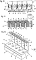
- Fig. 10 shows a plan view of another variant of a labeling system 1/3.
- This labeling system 1/3 is designed as a type of data magazine 35, which has a plurality of through holes 36.
- an implant screw 2 can be used, as can be seen from the sectional view XI-XI Fig. 11 is apparent.
- Fig. 11 it can be seen that each of the through bores 36 also has an upper, radially enlarged bore section 7, in each of which the corresponding screw head 8 of the associated implant screw 2 is fittingly received. Due to the radially expanded design of the bore portion 7, the through hole 36 forms a radially inwardly directed stop collar 37, on which the respective screw head 8 is supported vertically downwards in the attached state.
- the through holes 36 are each covered by a separate data carrier 38.
- These data carriers 38 are each provided with a corresponding lettering 19, as is made Fig. 10 is apparent.
- the implant screws 2 are captively secured in the respective through-bore 36 by the respectively associated data carrier 38.
- each data carrier 38 has a latching tab 39 which is arranged on a respective data carrier 38, which can be torn off via a type of film hinge 40.
- Each of the data carriers 38 is furthermore connected to the data magazine 35 via a further film hinge 41, which is opposite the latching tabs 39.
- the data magazine 35 which is block-shaped, forms in the region of its front end face 42 a holding web 43 projecting vertically upwards, on which the data carriers 38 rest in their closed state.
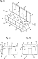
- an air gap 20 is likewise formed between the respective data carrier 38 and the surface 44 of the data magazine 35 so that sufficient sterilization agent, in particular for the screw head 8 of the implant screw 2, can pass through this air gap 20 for sterilization of the implant screw 2 received ( Fig. 14 ).
- the disk 38 with each other a lateral distance a from each other.
- Fig. 14 It can be seen that the latching tabs 39 form a latching lug 45 with which they can be brought into engagement with a corresponding latching groove 46 of the data magazine 35.
- This locking groove 46 extends, as is the case Fig. 12 It can be seen over the entire length of the front End face 42 of the data magazine 35.
- Fig. 12 and 14 Still seen that in the locking tabs 39 approximately in the region of their locking lugs 45 are each provided with an actuating bar 47 which serves to facilitate handling when unlocking these locking tabs 39.
- the respectively recorded implant screw 2 can be removed from the associated through-bore 36. Subsequently, the data carrier 38 is separated by tearing off the film hinge 41 from the data carrier magazine 35. In order to be able to attach this data carrier 38 in a simple manner to a patient document, the locking tab 39 can also be separated manually from the data carrier 38 via the living hinge 40, so that this data carrier 38 subsequently forms a flat plate-like element which, for example, is glued onto a patient document can.
- Fig. 13 shows a further embodiment of an identification system 1/4 in the form of a data magazine 35/1, wherein in Fig. 13 for the same parts the same reference numerals are entered as in the embodiment of the data magazine 35 Fig. 12 so that the description of the variant of the Fig. 12 so far as well Fig. 13 to read.
- This data magazine 35/1 also has a plurality of data carriers 38, which in Fig. 13 are shown in their respective open state and also have a lateral distance a from each other.
- the data carriers 38 are likewise connected in each case detachably via a film hinge 41 to the data magazine 35/1.
- the data magazine 35/1 in the region of its front end face 42 has a vertically upwardly directed holding web 43 on which the data carriers 38 rest in the closed state ( Fig. 15 ).
- the disk 38 have a distance from the surface 44 of the data magazine 35/1, so that between the disk 38 and this surface 44 also has an air gap 20 is present.
- the construction of the data magazine 35/1 differs from the construction of the data magazine 35 by the latching locking of its data carrier 38 in the closed state. It is off Fig. 14 recognizable that each disk 38 is assigned to the front end 42 each have a locking tab 50.
- This locking tab 50 is resiliently connected to the data magazine 35/1.
- For closed data carrier 38 towards each of the locking tabs 50 forms a respective disk 38 projecting locking lug 51, with which the locking tab 50 in the closed state of the respective associated data carrier 38 is positively, latching with this disk 38 is engaged.
- This variant has the advantage that the locking tab 50 with its locking lug 51 after tearing off the respective data carrier 38 via the respective film hinge 41 does not have to be additionally removed from the data carrier 38.
- the data carrier 38 according to the embodiment variant of the data magazine 35/1 can be mounted on or on a patient document immediately after detachment from the data magazine 35/1. Any disturbing protruding parts are therefore no longer available after disconnecting here.
- a sufficiently large labeling surfaces for the data to be stored is available for the marking of the implants.
- the respective implant data in a legible font size can be placed on the respective associated disk.
- Such a label can, as exemplified in the drawings, be mounted in "text form" on the corresponding disk.
- other types of data types are also conceivable.
- the characteristics for the implant can also be attached in the form of a data matrix or in RFID format on the data carrier.
- a data chip for example in the form of a readable transponder, conceivable, which is integrated as a separate component in the data carrier or glued to the disk.
Landscapes
- Health & Medical Sciences (AREA)
- Surgery (AREA)
- Life Sciences & Earth Sciences (AREA)
- Engineering & Computer Science (AREA)
- Molecular Biology (AREA)
- Public Health (AREA)
- Heart & Thoracic Surgery (AREA)
- Medical Informatics (AREA)
- Nuclear Medicine, Radiotherapy & Molecular Imaging (AREA)
- Animal Behavior & Ethology (AREA)
- General Health & Medical Sciences (AREA)
- Biomedical Technology (AREA)
- Veterinary Medicine (AREA)
- Physics & Mathematics (AREA)
- General Physics & Mathematics (AREA)
- Theoretical Computer Science (AREA)
- Oral & Maxillofacial Surgery (AREA)
- Pathology (AREA)
- Prostheses (AREA)
Description
- Die Erfindung betrifft ein Kennzeichnungssystem für medizinische Implantate, bei dem auf einer Beschriftungsfläche produktspezifische Daten, wie z. B. Hersteller, Charge oder sonstige Kennzeichnungsdaten unlöschbar aufgebracht sind, anhand derer die Herkunft oder die Eigenschaften oder die Herkunft und die Eigenschaften des betreffenden Implantats rückverfolgbar sind, wobei sich die Beschriftungsfläche auf einem Datenträger befindet, der die Form eines Plättchens, Schildchens oder Streifens aufweist.
- Bei den bekannten Kennzeichnungssystemen sind die Kennzeichnungsdaten eines Implantats unmittelbar auf dem Implantat selbst und/oder auf der Verpackung angebracht. Aus der
DE 20 2007 004 638 U1 ist beispielsweise eine Haltevorrichtung für die Aufnahme von Knochenschrauben bekannt, bei welcher auf einer Sichtfläche Implantatdaten angeordnet sind. Diese Haltevorrichtung weist einen Grundkörper auf, in welchen das Implantat über eine Art Rast- oder Klemmverbindung auslösbar eingesetzt ist. Mehrere solcher Haltevorrichtungen können zusammen mit dem aufgenommenen Implantat in eine Lagereinheit lösbar eingesetzt sein, wozu die Haltevorrichtung jeweils mit weiteren Rastelementen versehen ist. Für den Einsatz eines Implantates beispielsweise im menschlichen Körper wird zunächst die Haltevorrichtung aus der Lagereinheit entnommen. Anschließend wird das Implantat aus der Haltevorrichtung herausgenommen und in den Körper des Patienten eingesetzt. Weil das Implantat nach dem Einsetzen in den Körper des Patienten nicht mehr zugänglich ist und die Haltevorrichtung aufgrund ihrer Abmessungen nicht archivierbar ist, müssen die Daten zur Archivierung und Zuordnung zum jeweiligen Patienten von der Haltevorrichtung abgeschrieben und in die Patientenakte übertragen werden. Dabei können Übertragungsfehler entstehen, so dass eine zuverlässige Rückverfolgung nicht mit der erforderlichen Sicherheit gewährleistet ist. - In der
US 2002/0052607 A1 ist ein Implantat in Form einer Schädelplatte beschrieben an welcher eine Art Schildchen direkt angeformt ist. Dieses Schildchen bildet auf seiner dem Schädel des Patienten abgewandten Außenseite eine Beschriftungsfläche, welche diverse Daten der Schädelplatte, wie Nummer, Größe, Material und andere zugehörige Informationen enthält. Des Weiteren dient dieses Schildchen zur Erleichterung der manuellen Positionierung. Das Schildchen steht über eine "zerbrechliche" Verbindungsstelle mit der Schädelplatte in Verbindung, so dass das Schildchen, nachdem das Implantat am Schädel positioniert und befestigt wurde, manuell entfernt werden kann. - Beim Gegenstand der
DE 10 2007 011 093 B3 geht es um einen separaten Datenträger, welcher mit einem Implantat in Form einer Knochenplatte ein Eingriff bringbar ist. Hierzu ist der Datenträger mit einem blattfederartigen Betätigungselement versehen, das einen mittleren, aus der Ebene des Datenträgers hervorstehenden Betätigungsabschnitt aufweist. Der freie federelastisch bewegliche Endbereich des Betätigungselement ist "unterhalb" der Ebene des Datenträgers angeordnet und weist oberseitig einen Haltezapfen auf, welcher in eine der Bohrungen der Knochplatte einsetzbar ist. Zu beiden Seiten des Betätigungselementes sind U-Schenkel vorgesehen, welche sich seitlich bis in den Bereich des Haltezapfens erstrecken und mit ihren Endbereichen als an der Knochenplatte oberseitig ansetzbare Widerlager im Bereich des Haltezapfens dienen. Durch Betätigen der "Betätigungsabschnittes" kann der Haltezapfen mit der Bohrungen des Implantates außer Eingriff gebracht und vom Implantat entfernt werden. werden. Auf Grund dieser Abmessungen ist dieser Datenträger ebenfalls nicht archivierbar, insbesondere nicht in einer Patentenakte. - Beim Gegenstand der
WO 2009/024189 A2 geht es um die Kennzeichnung von Implantaten, insbesondere in Form einer Implantatschraube. Bei dieser Vorrichtung ist Lagerelement vorgesehen, an welchem zwei die Datenträger angeformt sind. Einer der Datenträger verläuft unterseitig parallel zur Achse einer aufzunehmenden Knochenschraube, während der zweite Datenträge als oberseitig seitlich abstehendes Element ausgebildet ist. Diesem Lagerelement 5 ist ein Aufnahmeelement 3 zugeordnet, welches in das Lagerelement einsteckbar ist und welches die Knochenschraube aufnimmt. Befindet sich dieses Aufnahmeelement im Lagerelement in einer Ausgangsstellung, so wird die Knochenschraube durch einen Haltebügel rastend sowohl im Aufnahmeelement als auch im Lagerelement gesichert. Durch Niederdrücken des Aufnahmeelementes relativ zum Lagerelement wird der Haltebügel in die in denFig. 2a bis 2e dargestellte Position zurückgestellt. In dieser Position, in welcher das Aufnahmeelement in das Lagerelement hinein verschoben wurde, wird die Knochenschraube durch den Haltebügel frei gegeben, so dass diese aus dem Aufnahmeelement herausgenommen werden kann. Von dem abgesehen, dass diese Vorrichtung zum Kennzeichnen einer Knochenschraube äußerst komplex aufgebaut ist, so ist auch diese Vorrichtung nicht in einer Patientenakte archivierbar. - Der Erfindung liegt demgemäß die Aufgabe zugrunde, ein Kennzeichnungssystem der eingangs genannten Art zu schaffen, in welchem ein Implantat einfach und sicher aufnehmbar ist und bei dem die Daten des benutzten Implantats in der vom Hersteller des Implantats angegebenen Form und Vollständigkeit in die Patientenakte aufnehmbar sind, um Übertragungsfehler zu vermeiden.
- Die Aufgabe wird erfindungsgemäß zusammen mit den Merkmalen des Oberbegriffes des Anspruches 1 dadurch gelöst, dass der Datenträger manuell abtrennbar mit einem das Implantat aufnehmenden Lagerelement verbunden ist und das Implantat im Lagerelement durch den Datenträger unverlierbar gesichert ist und, dass der abgetrennte Datenträger an oder auf einem Patientendokument mittels einer Kleb- oder einer Klammerverbindung unverlierbar befestigbar ist.
- Ein Datenträger in Form eines dünnen Plättchens, Schildchens oder Streifens lässt sich beispielsweise durch Kleben oder mittels Heftklammern leicht an einem aus Papier oder leichtem Karton bestehenden Patientendokument befestigen und zusammen mit diesem zur Archivierung aufbewahren.
- Mit einem solchen Kennzeichnungssystem, das leicht und ohne besondere Aufmerksamkeit sicher handhabbar ist, können Datenübertragungsfehler mit der gebotenen Sicherheit vermieden und die Daten der Implantate unverlierbar über längere Zeiträume zurückverfolgt werden.
- Ein besonderer Vorteil besteht auch darin, dass sich das erfindungsgemäße Kennzeichnungssystem sowohl für plattenförmige Implantate als auch für Implantate in Form von Implantatschrauben in gleich vorteilhafter Weise verwenden lässt.
- Hierzu kann zur Magazinierung von mehreren Aufnahmehülsen oder Implantatschrauben ein Aufnahmemagazin oder ein Datenträgermagazin vorgesehen sein, das zur Aufnahme der Aufnahmehülsen oder der mit einem Datenträger versehenen Implantatschrauben mehrere Aufnahmebohrungen oder Durchgangsbohrungen aufweist.
- Durch die erfindungsgemäßen Ausgestaltungen der Datenträger wird sichergestellt, dass ein Datenträger erst dann von der Implantatschraube bzw. deren Aufnahmehülse entfernt wird, wenn die Implantatschraube aus ihrer Aufnahmehülse entnommen wird. Damit ist eine erhöhte Kennzeichnungssicherheit gewährleistet.
- Weiter kann vorgesehen sein, dass der Verbindungsabschnitt der Aufnahmehülse sich an einer Stirnseite der Aufnahmehülse befindet und dass der Verbindungsabschnitt eine durch eine kerbenartige Vertiefung erzeugte Querschnittsverjüngung aufweist. Durch diese Ausgestaltung ist der Datenträger an der einen Stirnseite der Aufnahmehülse leicht zugänglich und kann durch die kerbenartige Vertiefung des Verbindungsabschnittes auch einfach manuell abgetrennt werden. Durch die Anordnung des Verbindungsabschnitts und damit auch des Datenträgers wird auch die Übersichtlichkeit erleichtert und damit die Handhabung verbessert.
- Zur einfachen Magazinierung von Implantatschrauben kann weiter vorgesehen sein, dass das Datenträgermagazin aus einem wenigstens eine Reihe von Durchgangsbohrungen für Implantatschrauben aufweisenden länglichen Block besteht, bei dem die Durchgangsbohrungen oberseitig durch einzelne, separat abtrennbare, den in den Bohrungen befindlichen Implantatschrauben zugeordneten Datenträger abgedeckt sind, deren Verbindungsabschnitte oberseitig außerhalb der Bohrungen liegen.
- Weiter kann der Datenträger und das Teil, mit dem er abreißbar verbunden ist aus Kunststoff bestehen. Ergänzend hierzu kann der Verbindungsabschnitt als Filmscharnier ausgebildet sein. Durch diese Ausgestaltungen kann ein Handhabungsvorteil insofern erzielt werden, als die Möglichkeit geschaffen wird, durch Hochklappen des Datenträgers die Einsteckbohrungen zum Einlegen einer Implantatschraube zu öffnen.
- Weiter kann vorgesehen sein, dass jeder Bohrung des aus Kunststoff bestehenden Datenträgermagazins zu deren Abdeckung ein als Deckel ausgebildeter Datenträger zugeordnet ist, der mittels eines Filmscharniers an einer Längskante eines das Datenträgermagazin bildenden Blocks aufklappbar und abreißbar angelenkt ist.
- Diese Ausgestaltung ist für die Magazinierung von mehreren Implantatschrauben in einem gemeinsamen Datenträgermagazin äußerst vorteilhaft. Insbesondere durch Anlenkung des als Deckel ausgebildeten Datenträgers über ein Filmscharnier am Datenträgermagazin ist ein Öffnen des Deckels (bzw. der Deckel) zur Bestückung des Datenträgermagazins in ebenso einfacher Weise durchführbar wie auch das abschließende Entfernen des Datenträgers.
- Zur Sicherung der Implantatschrauben im Datenträgermagazin kann vorgesehen sein, dass die Datenträger des Datenträgermagazins mittels eines abreißbaren Rastlasche in ihrer Schließlage am Datenträgermagazin verriegelbar sind.
- Darüber hinaus kann auch vorgesehen sein, dass die als schwenkbarer Deckel ausgebildeten Datenträger des Datenträgermagazins jeweils mittels einer an der Stirnfläche des Datenträgermagazins angeordneten Rastlasche in ihrer Schließlage fixierbar sind, wobei die Rastlasche den jeweils zugeordneten Datenträger mit einer Rastnase übergreift.
- Um eine einzelne Implantatschraube im Operationsbereich bereitzustellen, kann vorgesehen sein, dass die Kennzeichnungshülse einen axial verlängerten Standfuß mit einer unterseitigen, im Wesentlichen ebenen, etwa ringförmig ausgebildeten Standfläche aufweist.
- Anhand der Zeichnungen werden nachfolgend einige Ausführungsbeispiele der Erfindung näher erläutert. Es zeigt:
- Fig. 1
- eine perspektivische Darstellung einer ersten Ausführungsvariante eines Kennzeichnungssystems zusammen mit einem als Implantatschraube ausgebildeten Implantat;
- Fig. 2
- eine Schnittdarstellung II-II des Kennzeichnungssystems aus
Fig. 1 ; - Fig. 3
- eine zweite Ausführungsvariante eines Kennzeichnungssystems ohne Implantat;
- Fig. 4
- eine Schnittdarstellung IV-IV des Kennzeichnungssystems aus
Fig. 3 mit eingesetztem, als Implantatschraube ausgebildeten Implantat; - Fig. 5
- eine Schnittdarstellung V-V des Kennzeichnungssystems aus
Fig. 3 mit entferntem Datenträger; - Fig. 6
- ein plattenförmiges Aufnahmemagazin mit mehreren Aufnahmebohrungen zusammen mit einem Kennzeichnungssystem aus
Fig. 1 , welches in eine der Aufnahmebohrungen eingesetzt ist; - Fig. 7
- eine Schnittdarstellung VII-VII aus
Fig. 6 mit mehreren in die Aufnahmebohrungen des Aufnahmemagazins eingesetzten Kennzeichnungssystemen ausFig. 1 ; - Fig. 8
- eine perspektivische Darstellung einer weiteren Ausführungsvariante eines Kennzeichnungssystems, welches mit einem Standfuß versehen ist;
- Fig. 9
- eine Schnittdarstellung IX-IX des Kennzeichnungssystems aus
Fig. 8 mit eingesetztem, als Implantatschraube ausgebildeten Implantat; - Fig. 10
- eine Draufsicht eines Datenträgermagazins, welches mehrere plättchenförmige Datenträger aufweist;
- Fig. 11
- eine Schnittdarstellung XI-XI des Datenträgermagazins aus
Fig. 10 mit mehreren als Implantatschrauben ausgebildeten Implantaten; - Fig. 12
- das Datenträgermagazin aus den
Fig. 10 und 11 in perspektivischer Darstellung mit geöffneten Datenträgern; - Fig. 13
- eine zweite Ausführungsvariante eines Datenträgermagazins in perspektivischer Darstellung;
- Fig. 14
- eine Seitenansicht XIV des Datenträgermagazins aus
Fig. 12 ; - Fig. 15
- eine Seitenansicht XV des Datenträgermagazins aus
Fig. 13 ; -
Fig. 1 zeigt eine perspektivische Darstellung einer ersten Ausführungsvariante eines Kennzeichnungssystems 1, welches zur Aufnahme eines als Implantatschraube 2 ausgebildetes Implantats dient. Dieses Kennzeichnungssystem 1 besteht aus einer Aufnahmehülse 3, welche nach unten hin eine radial verjüngt ausgebildete Steckhülse 4 bildet. Im oberen Endbereich ist auf die Steckhülse 4 ein radial erweitertes Kopfteil 5 aufgesetzt, welches einstückig mit der Steckhülse 4 in Verbindung steht. Wie aus der Schnittdarstellung derFig. 2 ersichtlich ist, weist diese Aufnahmehülse 3 eine mehrfach abgesetzte Durchgangsbohrung 6 auf, welche im Bereich des Kopfteiles 5 mit einem radial erweiterten Bohrungsabschnitt 7 versehen ist. Dieser Bohrungsabschnitt 7 dient zur Aufnahme eines Schraubenkopfes 8 der Implantatschraube 2. Wie ausFig. 2 ersichtlich ist, stützt sich der Schraubenkopf 8 in der Durchgangsbohrung 6 an einem radial nach innen vorstehenden Stützsteg 9 axial ab, so dass die Implantatschraube 2 gegen Herausfallen aus der Aufnahmehülse 3 in Richtung des Pfeiles 10 gesichert ist. - Des Weiteren ist aus
Fig. 1 und 2 ersichtlich, dass die Aufnahmehülse 3 im Umgebungsbereich des radial erweiterten Bohrungsabschnittes 7 einen vertikal über die obere Ringfläche 11 des Kopfteiles 5 nach oben überstehenden Haltesteg 12 aufweist. Auf diesen Haltesteg 12 ist ein etwa plättchenförmig ausgebildeter Datenträger 13 aufgesetzt, welcher auf der Oberseite des Haltesteges 12 beispielsweise durch eine Kleb- oder Schweißverbindung gehalten ist. - Des Weiteren ist aus den
Fig. 1 und 2 ersichtlich, dass der Datenträger 13 im Bereich des Haltesteges 12 oberseitig mit einer quer verlaufenden Kerbe 14 versehen ist, so dass in diesem Bereich der Kerbe 14 ein filmscharnierartig ausgebildeter Verbindungsabschnitt 15 zwischen dem auf den Haltesteg 12 aufgesetzten und mit diesem feststehend verbundenen Halteabschnitt 16 des Datenträgers 13 und einem plättchenförmig ausgebildeten, seitlich über das Kopfteil 5 der Aufnahmehülse 3 vorstehenden Datenträgerabschnitt 17 gebildet wird. Dieser Datenträgerabschnitt 17 weist auf seiner Oberseite einer Beschriftungsfläche 18 mit einer Beschriftung 19 auf, durch welche die aufgenommene Implantatschraube 2 bezüglich ihrer Größe, Charge, ihres Herstellers und sonstiger Daten gekennzeichnet ist. - Weiter ist aus
Fig. 2 ersichtlich, dass zwischen dem Datenträger 13 bzw. dessen Datenabschnitt 17 und der obern Ringfläche 11 ein Luftspalt 20 gebildet wird. Dieser Luftspalt 20 weist dementsprechend auch einen Abstand zum Bohrungsabschnitt 7 auf, so dass zum Zwecke der Sterilisation der Implantatschraube 2 auch deren Schraubenkopf 8 mit Sterilisationsmittel beaufschlagt werden kann. - Beim dargestellten Kennzeichnungssystem 1 ist der Datenabschnitt 17 des Datenträgers 13 aufgrund des geschwächt ausgebildeten Verbindungsabschnittes 15 vom Halteabschnitt 16 und damit von der Aufnahmehülse 3 manuell in einfacher Weise abreißbar. Dadurch wird gleichzeitig die Implantatschraube 2 freigegeben, so dass diese entgegen des Pfeiles 10 aus der Aufnahmehülse 3 herausnehmbar ist. Nach dem Abtrennen des Datenabschnittes 17 kann dieser aufgrund seiner äußerst "flachen", plättchenartigen Ausgestaltung in einfacher Weise in einer Patientenakte oder einem Patientendokument archiviert werden. Hierzu ist es beispielsweise möglich, diesen Datenabschnitt 17 des Datenträgers 13 in die Patientenakte oder auf das Patientendokument einzukleben bzw. aufzukleben. Das Kennzeichnungssystem 1 sowie auch die weiter noch beschriebenen Kennzeichnungssysteme sind vorzugsweise aus Kunststoff hergestellt, so dass insbesondere das Abreißen des Datenabschnittes 17 des Datenträgers 13 vom Halteabschnitt 16 in einfacher Weise manuell durchführbar ist.
-
Fig. 3 zeigt eine weitere Ausführungsvariante eines Kennzeichnungssystems 1/1, bei welchem für identische oder gleich wirkende Teile dieselben Bezugszeichen eingetragen sind wie bei der Ausführungsvariante des Kennzeichnungssystems 1 aus denFig. 1 und 2 . Es ist erkennbar, dass der Datenträger 13 auf seiner Oberseite ebenfalls mit einer Beschriftung 19 versehen ist. Die Aufnahmehülse 3 weist ebenfalls eine radial verjüngt ausgebildete Steckhülse 4 auf, an welcher sich oberseitig ein radial erweitertes Kopfteil 5 anschließt. Bei dieser Ausführungsvariante des Kennzeichnungssystem 1/1 ist der Datenträger 13 auf zwei axial nach oben über die obere Ringfläche 11 des Kopfteiles 5 hinaus stehende Haltestege 12 bzw. 21 aufgesetzt. Auch hier besteht zwischen dem Datenträger 13 und dieser Ringfläche 11 des Kopfteiles 5 ein Luftspalt 20, wie dies insbesondere aus der Schnittdarstellung derFig. 4 erkennbar ist. Auch die Aufnahmehülse 3 weist eine Durchgangsbohrung 6 mit einem oberen, radial erweiterten Bohrungsabschnitt 7 auf. In diesem radial erweiterten Bohrungsabschnitt 7 wird hier ebenfalls der Schraubenkopf 8 einer Implantatschraube 2 aufgenommen. Dieser Schraubenkopf 8 stützt sich vertikal in Richtung des Pfeiles 10 nach unten an einem radial nach innen vorstehenden Stützsteg 9 der Bohrung 6 ab. Somit wird die in die Bohrung 6 eingesetzte Implantatschraube 2 durch diesen Stützsteg 9 gegen Herausfallen in Richtung des Pfeiles 10 gesichert. - Der Datenträger 13 ist auch bei dieser Ausführungsvariante im Abstand zur oberen Ringfläche 11 des Kopfteiles 5 angeordnet und deckt die Durchgangsbohrung 6 oberseitig vollständig ab. Dadurch ist die Implantatschraube 2 gegen Herausfallen in entgegengesetzter Richtung zum Pfeil 10 in der Durchgangsbohrung 6 gesichert.
- Die Verbindung des Datenträgers 13 mit der Aufnahmehülse 3 besteht bei der Ausführungsvariante nach
Fig. 3 aus zwei "Schweißpunkten" 22, über welche der Datenträger 13 mit dem Haltesteg 12 feststehend in Verbindung steht. Diese Schweißpunkte 22 sind derart ausgestaltet, dass diese durch Anheben des Datenträgers 13 entgegen des Pfeiles 10 aufgebrochen werden können, so dass die Durchgangsbohrung 6 bzw. deren radial erweiterter Bohrungsabschnitt 7 freigegeben wird. Nach dem Abtrennen des Datenträgers 13 durch Aufbrechen der beiden Schweißpunkte 22 wird somit die Durchgangsbohrung 6 nach oben freigegeben, so dass die Implantatschraube 2 aus der Aufnahmehülse 3 herausnehmbar ist. Der Datenträger 13 kann nach dem Abtrennen aufgrund seiner äußerst flachen, plättchenartigen Ausbildung ebenfalls in einfacher Weise zur Archivierung unverlierbar an oder auf einem Patientendokument befestigt werden. Damit ist eine eindeutige Zuordnung des entsprechenden beim Patienten eingesetzten Implantats in Form der Implantatschraube 2 stets gewährleistet.Fig. 5 zeigt hierzu die Aufnahmehülse 3 mit abgerissenem Datenträger 13. Es ist deutlich erkennbar, dass die beiden Haltestege 12 und 21 vertikal über die Ringfläche 11 des Kopfteiles 5 hinaus stehen. - Durch das Abreißen des Datenträgers 13 bzw. des Datenabschnittes 17 wird des Weiteren sichergestellt, dass dieser Datenträger 13 bzw. der Datenabschnitt 17 nicht wieder einem anderen Implantat bzw. einer anderen Implantatschraube 2 zugeordnet werden kann. D.h., dass auch hier durch das Abtrennen des Datenträgers 13 bzw. Datenabschnittes 17 sichergestellt ist, dass das Kennzeichnungssystem 1 bzw. 1/1 nicht erneut mit einem Implantat bzw. einer Implantatschraube 2 bestückt wird. Insoweit bildet das Kennzeichnungssystem 1 bzw. 1/1 in vielerlei Hinsicht eine äußerst sichere Kennzeichnung einer Implantatschraube 2, da diese einerseits durch die Abdeckung der Durchgangsbohrung 6 durch den Datenträger 13 nicht aus dem Kennzeichnungssystem 1 bzw.1/1 entnehmbar ist, ohne dass dies für den Operateur erkennbar wäre.
- Insoweit ist die Kennzeichnung durch dieses Kennzeichnungssystem 1 bzw. 1/1 insbesondere einer Implantatschraube 2 stets eindeutig und kann nicht zu Verwechslungen führen. Da der Datenträger 13 aufgrund seiner plättchenförmigen Ausgestaltung unverlierbar mit dem Patientendokument verbindbar ist, ist auch nach dem Einsetzen der Implantatschraube 2 in den Körper eines Patienten eine einwandfreie und unverwechselbare Zuordnung gewährleistet. Insbesondere können hier auch keine Übertragungsfehler der Kennzeichnungsdaten 19 zum Patienten bzw. zum implantierten Implantat 2 auftreten.
- Durch die spezielle Ausgestaltung der Kennzeichnungssysteme 1 und 1/1 und insbesondere deren Aufnahmehülse 3 sind diese in einfacher Weise magazinierbar. So zeigt
Fig. 6 eine perspektivische Darstellung eines plattenförmigen Aufnahmemagazins 25, welches bei der dargestellten Ausführungsvariante mit insgesamt fünf in einer Reihe angeordneten Aufnahmebohrungen 26 versehen ist. Ein solches Aufnahmemagazin 25 dient zur Bereitstellung mehrerer Implantate, insbesondere Implantatschrauben 2, während einer Operation. Wie ausFig. 6 ersichtlich ist, ist in die mittlere Aufnahmebohrung 26 ein Kennzeichnungssystem 1 ausFig. 1 eingesetzt. Der Durchmesser dieser Aufnahmebohrung 26 entspricht dem Durchmesser der Steckhülse 4 (Fig. 1 ), so dass die Aufnahmehülse 3 passend in eine der Aufnahmebohrungen 26 einsteckbar ist. Dabei stützt sich die Aufnahmehülse 3 mit ihrem radial erweiterten Kopfteil 5 auf der Oberfläche 27 des Aufnahmemagazins 25 im Umgebungsbereich der zugehörigen Aufnahmebohrung 26 axial ab. Es ist leicht vorstellbar, dass mehrere solcher Kennzeichnungssysteme 1 in das Aufnahmemagazin 25 einsetzbar sind. - Hierzu zeigt
Fig. 7 eine entsprechende Schnittdarstellung VII-VII ausFig. 6 . Es ist erkennbar, dass insgesamt fünf Kennzeichnungssysteme 1 in die jeweils zugehörige Aufnahmebohrung 26 des Aufnahmemagazins 25 mit ihrer jeweiligen Steckhülse 4 eingesetzt sind. Mit ihren radial erweiterten Kopfteilen 5 stützt sich jedes der Kennzeichnungssysteme 1 auf der Oberfläche 27 des Aufnahmemagazins 25 ab. Bei der dargestellten Ausführungsvariante des Aufnahmemagazins 25 durchragen die in den Kennzeichnungssystemen 1 aufgenommenen Implantatschrauben 2 das Aufnahmemagazin 25 vertikal nach unten. Insoweit kann das plattenförmige Aufnahmemagazin 25 in eine weitere entsprechend ausgebildete Aufnahmeeinrichtung einsetzbar sein, so dass die Kennzeichnungssysteme 1 mit ihren aufgenommenen Implantatschrauben 2 nicht aus den Aufnahmebohrungen 26 des Aufnahmemagazins 25 herausgedrückt werden. Auch ist eine senkrechte Ausrichtung des Aufnahmemagazins 25 denkbar. -
Fig. 8 zeigt eine perspektivische Darstellung einer weiteren Ausführungsvariante eines Kennzeichnungssystems 1/2. Dieses Kennzeichnungssystem 1/2 weist ebenfalls einen Datenträger 13 auf, auf dessen Oberseite ebenfalls eine Beschriftung 19 angebracht ist. Dieser Datenträger 13 ist, in ähnlicher Weise wie der Datenträger 13 nach der Ausführungsvariante des Kennzeichnungssystems 1/1 ausFig. 3 , über zwei Schweißpunkte 22 mit der Aufnahmehülse 3 abreißbar verbunden. Auch der Datenträger 13 der Ausführungsvariante des Kennzeichnungssystems 1/2 weist zur oberen Ringfläche 11 des Kopfteiles 5 der Aufnahmehülse 3 einen Abstand auf, so dass zwischen dem Datenträger 13 und der Ringfläche 11 ebenfalls ein Luftspalt 20 gebildet wird, dessen Größe dem vertikalen Überstand nach oben des Haltesteges 12 entspricht. Weiter ist insbesondere aus der Schnittdarstellung IX-IX derFig. 9 erkennbar, dass auch die Aufnahmehülse 3 eine Durchgangsbohrung 6 aufweist, welche ebenfalls abgesetzt ausgebildet ist. Die Implantatschraube 2 ist in diese Durchgangsbohrung 6 eingesetzt, wobei deren Schraubenkopf 8 in einem radial erweiterten Abschnitt 7 der Durchgangsbohrung 6 aufgenommen wird. Diese Ausführungsvariante des Kennzeichnungssystems 1/2 weist in vertikal nach unten gerichteter Verlängerung zur Aufnahmehülse 3 einen Standfuß 30 auf, dessen Länge derart ausgebildet ist, dass die eingesetzte Implantatschraube 2 nicht aus der Durchgangsbohrung 6 vertikal nach unten herausragen kann. Somit bildet dieser Standfuß 30 unterseitig eine ringförmige Standfläche 31, mit welcher das Kennzeichnungssystem 1/2 auf einem ebenen Untergrund aufstellbar ist. - Des Weiteren ist aus
Fig. 9 erkennbar, dass die Durchgangsbohrung 6 unterhalb des radial erweiterten Bohrungsabschnittes 7 einen radial nach innen vorstehenden Stützsteg 9 bildet, an welchem sich der Schraubenkopf 8 der Implantatschraube 2 vertikal abstützt. Das Kennzeichnungssystem 1/2 ist insbesondere vorgesehen, um Implantatschrauben 2 als "Einzelstücke" dem Operateur zur Verfügung zu stellen. -
Fig. 10 zeigt eine Draufsicht einer weiteren Variante eines Kennzeichnungssystems 1/3. Dieses Kennzeichnungssystem 1/3 ist als eine Art Datenmagazin 35 ausgebildet, welches mehrere Durchgangsbohrungen 36 aufweist. In diese Durchgangsbohrungen 36 ist jeweils eine Implantatschraube 2 einsetzbar, wie dies aus der Schnittdarstellung XI-XI derFig. 11 ersichtlich ist. Weiter ist ausFig. 11 ersichtlich, dass jede der Durchgangsbohrungen 36 ebenfalls einen oberen, radial erweiterten Bohrungsabschnitt 7 aufweist, in welchem jeweils der entsprechende Schraubenkopf 8 der zugehörigen Implantatschraube 2 passend aufgenommen wird. Aufgrund der radial erweiterten Ausbildung des Bohrungsabschnittes 7 bildet die Durchgangsbohrung 36 einen radial nach innen gerichteten Anschlagbund 37, an welchem sich der jeweilige Schraubenkopf 8 im angesetzten Zustand vertikal nach unten abstützt. - Weiter ist aus den
Fig. 10 und 11 erkennbar, dass die Durchgangsbohrungen 36 jeweils mittels eines separaten Datenträgers 38 abgedeckt sind. Diese Datenträger 38 sind jeweils mit einer entsprechenden Beschriftung 19 versehen, wie dies ausFig. 10 ersichtlich ist. Im geschlossenen Zustand werden die Implantatschrauben 2 in der jeweiligen Durchgangsbohrung 36 durch den jeweils zugehörigen Datenträger 38 unverlierbar gesichert. Dabei zeigtFig. 11 einen teilweise geöffneten Zustand eines der Datenträger 38, wobei die diesbezüglich zugeordnete Implantatschraube bereits herausgenommen ist. Nachdem die Implantatschraube 2 herausgenommen ist, kann der Datenträger 38 in einfacher Weise vom Datenmagazin 35 abgenommen werden. - Hierzu zeigt
Fig. 12 das Datenmagazin 35 in perspektivischer Darstellung. Alle Datenträger 38 sind in der Darstellung derFig. 12 in ihrem geöffneten Zustand dargestellt. Weiter ist ausFig. 12 ersichtlich, dass jeder Datenträger 38 eine Rastlasche 39 aufweist, welche über eine Art Filmscharnier 40 abreißbar am jeweiligen Datenträger 38 angeordnet ist. Jeder der Datenträger 38 ist des Weiteren über ein weiteres, den Rastlaschen 39 gegenüberliegendes Filmscharnier 41 mit dem Datenmagazin 35 verbunden. Des Weiteren bildet das Datenmagazin 35, welches blockartig ausgebildet ist, im Bereich seiner vorderen Stirnseite 42 einen vertikal nach oben vorstehenden Haltesteg 43, auf welchem die Datenträger 38 in ihrem geschlossenen Zustand aufliegen. Damit wird zwischen dem jeweiligen Datenträger 38 und der Oberfläche 44 des Datenmagazins 35 ebenfalls ein Luftspalt 20 gebildet, so dass durch diesen Luftspalt 20 zur Sterilisation der aufgenommenen Implantatschraube 2 ausreichend Sterilisationsmittel, insbesondere zum Schraubenkopf 8 der Implantatschraube 2, gelangen kann (Fig. 14 ). Zu Verbesserung dieser Zufuhr weisen die Datenträger 38 untereinander eine seitlichen Abstand a voneinander auf. - Des Weiteren ist aus
Fig. 14 ersichtlich, dass die Rastlaschen 39 eine Rastnase 45 bilden, mit welcher diese rastend mit einer entsprechenden Rastnut 46 des Datenmagazins 35 in Eingriff bringbar sind. Diese Rastnut 46 erstreckt sich dabei, wie dies ausFig. 12 ersichtlich ist, über die komplette Länge der vorderen Stirnseite 42 des Datenmagazins 35. Weiter ist aus denFig. 12 und14 noch ersichtlich, dass in den Rastlaschen 39 etwa im Bereich ihrer Rastnasen 45 jeweils mit einer Betätigungsleiste 47 versehen sind, welche zur leichteren Handhabung beim Entriegeln dieser Rastlaschen 39 dient. - Nach dem Öffnen des jeweiligen Datenträgers 38 kann die jeweils aufgenommene Implantatsschraube 2 aus der zugehörigen Durchgangsbohrung 36 herausgenommen werden. Anschließend wird der Datenträger 38 durch Abreißen des Filmscharniers 41 vom Datenträgermagazin 35 abgetrennt. Um diesen Datenträger 38 nun in einfacher Weise auf einem Patientendokument anbringen zu können, kann die Rastlasche 39 über das Filmscharnier 40 ebenfalls manuell vom Datenträger 38 abgetrennt werden, so dass dieser Datenträger 38 anschließend ein ebenes plättchenartiges Element bildet, welches beispielsweise auf einem Patientendokument aufgeklebt werden kann.
-
Fig. 13 zeigt eine weitere Ausführungsvariante eines Kennzeichnungssystems 1/4 in Form eines Datenmagazins 35/1, wobei inFig. 13 für die gleichen Teile die gleichen Bezugszeichen eingetragen sind wie bei der Ausführungsvariante des Datenmagazins 35 ausFig. 12 , so dass die Beschreibung zur Ausführungsvariante derFig. 12 insoweit auch aufFig. 13 zu lesen ist. - Dieses Datenmagazin 35/1 weist ebenfalls mehrere Datenträger 38 auf, welche in
Fig. 13 in ihrem jeweils geöffneten Zustand dargestellt sind und ebenfalls ein seitlichen Abstand a voneinander aufweisen. Die Datenträger 38 sind ebenfalls jeweils über ein Filmscharnier 41 mit dem Datenmagazin 35/1 abtrennbar verbunden. Den Filmscharnieren 41 gegenüberliegend weist auch das Datenmagazin 35/1 im Bereich seiner vorderen Stirnseite 42 einen vertikal nach oben gerichteten Haltesteg 43 auf, auf welchem die Datenträger 38 in geschlossenem Zustand aufliegen (Fig. 15 ). Weiter ist ebenfalls ausFig. 15 ersichtlich, dass aufgrund der vertikalen Höhe der Filmscharniere 41 sowie des Haltesteges 43 die Datenträger 38 einen Abstand zur Oberfläche 44 des Datenmagazins 35/1 aufweisen, so dass zwischen dem Datenträger 38 und dieser Oberfläche 44 ebenfalls ein Luftspalt 20 vorhanden ist. - Die Konstruktion des Datenmagazins 35/1 unterscheidet sich von der Konstruktion des Datenmagazins 35 durch die rastende Arretierung ihrer Datenträger 38 in geschlossenem Zustand. Es ist aus
Fig. 14 erkennbar, dass jedem Datenträger 38 an der vorderen Stirnseite 42 jeweils eine Rastlasche 50 zugeordnet ist. Diese Rastlasche 50 ist federelastisch mit dem Datenmagazin 35/1 verbunden. Zum geschlossenen Datenträger 38 hin bildet jede der Rastlaschen 50 eine zum jeweiligen Datenträger 38 hin vorstehende Rastnase 51, mit welcher die Rastlasche 50 im geschlossenen Zustand des jeweils zugehörigen Datenträgers 38 formschlüssig, rastend mit diesem Datenträger 38 in Eingriff steht. Diese Ausführungsvariante hat den Vorteil, dass die Rastlasche 50 mit ihrer Rastnase 51 nach dem Abreißen des jeweiligen Datenträgers 38 über dessen jeweiliges Filmscharnier 41 nicht noch zusätzlich vom Datenträger 38 entfernt werden muss. Dadurch kann der Datenträger 38 nach der Ausführungsvariante des Datenmagazins 35/1 unmittelbar nach dem Abtrennen vom Datenmagazins 35/1 auf oder an einem Patientendokument angebracht werden. Irgendwelche störend abstehenden Teile sind dementsprechend nach dem Abtrennen hier nicht mehr vorhanden. - Die Handhabung der Datenmagazine 35 und 35/1 aus den
Fig. 12 und13 wird nachfolgend nochmals näher erläutert:
Zum Entnehmen einer Implantatschraube 2 aus einem Magazin 35 bzw. 35/1 wird zuerst die jeweilige Rastlasche 39 bzw. 50 des entsprechenden Datenträgers 38 gelöst. Anschließend wird der Datenträger 38 aus seiner die Implantatschraube 2 überdeckenden Lage durch Verschwenken nach oben geöffnet. Danach kann die betreffende Implantatschraube 2 aus der zugehörigen Durchgangbohrung 36 des Magazins 35 bzw. 35/1 entnommen werden. Anschließend wird der dieser Implantatschraube 2 zugeordnete Datenträger 38 durch Abreißen des Filmscharniers 41 vom Datenmagazin 35 bzw. 35/1 abgetrennt und umgehend auf ein Datenblatt der Patientenakte des gerade behandelten Patienten geheftet oder geklebt. Wie bereits erwähnt, kann dies z. B. durch einen sich bereits auf dem Datenblatt des Patienten befindenden Klebstreifen oder mittels einer Klammer erfolgen. In jedem Falle muss eine dauerhaft haltbare Verbindung zwischen dem Datenträger 38 und dem Datenblatt gewährleistet sein. - Bei allen Ausführungsformen steht für die Kennzeichnung der Implantate eine ausreichend große Beschriftungsflächen für die zu speichernden Daten zur Verfügung. Damit können die erforderlichen, das jeweilige Implantat betreffenden Daten in einer gut leserlichen Schriftgröße auf den jeweils zugehörigen Datenträger gebracht werden. Eine solche Beschriftung kann, wie dies beispielhaft in den Zeichnungen dargestellt ist, in "Textform" auf dem entsprechenden Datenträger angebracht sein. Es sind jedoch auch andere Datenkennzeichnungsarten denkbar. So können die Kenndaten für das Implantat auch in Form einer Datamatrix oder im RFID-Format auf dem Datenträger angebracht sein. Auch ist ein Datenchip, beispielsweise in Form eines auslesbaren Transponders, denkbar, welcher als separates Bauteil im Datenträger integriert oder auf den Datenträger aufgeklebt ist.
- Damit ist es nicht erforderlich, die zu archivierenden Daten zum jeweiligen Implantat durch Abschrift in die Patientenakte aufzunehmen. So wird eine häufige Fehlerquelle bei der Archivierung und Zuordnung dieser Daten zur Patientenakte ausgeschlossen. Es kann folglich auch keine Übertragungsfehler geben. Dabei ist es von untergeordneter Bedeutung, welche konkrete äußere Form die Datenträger im Einzelnen haben und in welcher Weise die Daten auf diesen aufgebracht sind. Diese können beispielsweise unlöschbar aufgedruckt oder aufgeprägt sein.
Claims (10)
- Kennzeichnungssystem (1, 1/1, 1/2, 1/3, 1/4) für medizinische Implantate (2), bei dem auf einer Beschriftungsfläche (18) produktspezifische Daten (19), wie z.B. Größe, Hersteller, Charge oder sonstige Kennzeichnungsdaten unlöschbar aufgebracht sind, anhand derer die Herkunft oder die Eigenschaften oder die Herkunft und die Eigenschaften des betreffenden Implantats (2, 75) rückverfolgbar sind, wobei sich die Beschriftungsfläche (18) auf einem Datenträger (13, 38) befindet, der die Form eines Plättchens, Schildchens oder Streifens aufweist, wobei der abgetrennte Datenträger (13, 38) an oder auf einem Patientendokument mittels einer Kleb- oder einer Klammerverbindung unverlierbar befestigbar ist; dadurch gekennzeichnet,
dass der Datenträger (13, 38) manuell abtrennbar mit einem das Implantat (2) aufnehmenden Lagerelement (3, 35, 35/1) verbunden ist und das Implantat (2) im Lagerelement (3, 35, 35/1) durch den Datenträger (13, 18) unverlierbar gesichert ist. - Kennzeichnungssystem nach Anspruch 1, dadurch gekennzeichnet, dass das Lagerelement hülsenförmig ausgebildet ist und eine Aufnahmehülse (3) mit einer abgesetzten Aufnahmebohrung (6) für ein als Implantatschraube (2) ausgebildetes Implantat aufweist und,
dass die das Implantat (2) aufnehmende Aufnahmebohrung (6) durch den Datenträger (13) abgedeckt ist und,
dass der Datenträger (13) über einen abreißbaren Verbindungsabschnitt (15) mit der Aufnahmehülse (3) in Verbindung steht. - Kennzeichnungssystem nach Anspruch 2, dadurch gekennzeichnet, dass die Aufnahmehülse (3) eine Steckhülse (4) mit einem radial erweiterten Kopfteil (5) bildet und, dass der Datenträger (13) auf dem Kopfteil (5), die Aufnahmebohrung (6) abdeckend angeordnet ist und, dass die Aufnahmehülse (3) mit ihrer Steckhülse (4) in eine von mehreren Aufnahmebohrungen (26) eines Aufnahmemagazins (25) einsteckbar ist.
- Kennzeichnungssystem nach Anspruch 2 oder 3, dadurch gekennzeichnet, dass der Verbindungsabschnitt (15) zwischen dem Datenträger (13) und der Aufnahmehülse (3) durch eine kerbenartige Querschnittsverjüngung (14) gebildet und als eine Art Filmscharnier ausgebildet ist.
- Kennzeichnungssystem nach Anspruch 2, 3 oder 4, dadurch gekennzeichnet, dass die Aufnahmehülse (3) einen axial verlängerten Standfuß (30) mit einer unterseitigen, im Wesentlichen ebenen, etwa ringförmig ausgebildeten Standfläche (31) aufweist.
- Kennzeichnungssystem nach Anspruch 1, dadurch gekennzeichnet, dass das Lagerelement zur Aufnahme mehrerer Implantate in Form von Implantatschrauben (2) als Datenträgermagazin (35, 35/1) ausgebildet ist, das mehrere die Implantate (2) aufnehmende Durchgangsbohrungen (36) aufweist, welche oberseitig durch einzelne, separat abtrennbare, den in den Durchgangsbohrungen (36) befindlichen Implantatschrauben (2) jeweils zugeordnete Datenträger (38) abgedeckt sind.
- Kennzeichnungssystem nach Anspruch 6, dadurch gekennzeichnet, dass der der jeweiligen Durchgangsbohrung (36) des aus Kunststoff bestehenden Datenträgermagazins (35, 35/1) zu deren Abdeckung zugeordnete Datenträger (38) mittels eines Filmscharniers (41) an einer Längskante eines das Datenträgermagazin (35, 35/1) bildenden Blocks aufklappbar und abreißbar angelenkt ist.
- Kennzeichnungssystem nach Anspruch 6 oder 7, dadurch gekennzeichnet, dass die Datenträger (38) des Datenträgermagazins (35) mittels einer abreißbaren Rastlasche (39) in ihrer Schließlage am Datenträgermagazin (35) verriegelbar sind.
- Kennzeichnungssystem nach Anspruch 6 oder 7, dadurch gekennzeichnet, dass die als schwenkbarer Deckel ausgebildeten Datenträger (38) des Datenträgermagazins (35/1) jeweils mittels einer an der Stirnfläche (42) des Datenträgermagazins (35/1) angeordneten Ratlasche (50) in ihrer Schließlage fixierbar sind, wobei die Rastlasche (50) den jeweils zugeordneten Datenträger (38) mit einer Rastnase (51) übergreift.
- Kennzeichnungssystem nach der Anspruch 1, dadurch gekennzeichnet, dass der Datenträger (13, 38) aus Kunststoff oder einem metallischen Werkstoff besteht.
Applications Claiming Priority (1)
| Application Number | Priority Date | Filing Date | Title |
|---|---|---|---|
| DE202010007487U DE202010007487U1 (de) | 2010-06-01 | 2010-06-01 | Kennzeichnungssystem für medizinische Implantate |
Publications (2)
| Publication Number | Publication Date |
|---|---|
| EP2392284A1 EP2392284A1 (de) | 2011-12-07 |
| EP2392284B1 true EP2392284B1 (de) | 2018-12-19 |
Family
ID=42814192
Family Applications (1)
| Application Number | Title | Priority Date | Filing Date |
|---|---|---|---|
| EP11004528.3A Not-in-force EP2392284B1 (de) | 2010-06-01 | 2011-06-01 | Kennzeichnungssystem für medizinische Implantate |
Country Status (2)
| Country | Link |
|---|---|
| EP (1) | EP2392284B1 (de) |
| DE (1) | DE202010007487U1 (de) |
Families Citing this family (5)
| Publication number | Priority date | Publication date | Assignee | Title |
|---|---|---|---|---|
| FR3000380B1 (fr) * | 2012-12-31 | 2016-02-12 | Neosteo | Ensemble du type comprenant au moins un implant, un prehenseur, et un element de tracabilite de l'implant, et procede de manipulation de maniere tracable de l'implant d'un tel ensemble |
| US9839459B2 (en) | 2012-12-31 | 2017-12-12 | Neosteo | Assembly including at least one implant, one gripping device and one element for the traceability of the implant, and method for traceably handling the implant of such an assembly |
| EP3062728B1 (de) | 2013-11-01 | 2021-12-08 | Smith & Nephew, Inc. | Medizinisches implantatabgabesystem und -verfahren sowie implantat mit einem abnehmbarem markierungsabschnitt |
| DE102013019452B4 (de) * | 2013-11-21 | 2019-05-29 | Rose Plastic Ag | Einzelverpackung für langgestreckte Gegenstände |
| DE102021130523A1 (de) | 2021-11-22 | 2023-05-25 | MAXXOS - Medical GmbH | Verfahren und Vorrichtung zum Nachverfolgen eines Implantats |
Family Cites Families (5)
| Publication number | Priority date | Publication date | Assignee | Title |
|---|---|---|---|---|
| WO2002024079A1 (en) * | 2000-09-22 | 2002-03-28 | Codman & Shurtleff, Inc. | Instrument and method for applying surgical fastners |
| NZ550345A (en) * | 2004-03-07 | 2009-11-27 | Synthes Gmbh | Container and carrier system for holding and presenting surgical materials such as bone screws |
| DE102007011093B3 (de) * | 2007-02-28 | 2008-06-19 | Aesculap Ag & Co. Kg | Chirurgischer Datenträger |
| DE202007004638U1 (de) | 2007-03-22 | 2007-06-14 | Aesculap Ag & Co. Kg | Haltevorrichtung für ein Implantat |
| EP2187832B1 (de) * | 2007-08-22 | 2021-06-30 | Medartis Holding AG | Träger zur aufnahme von chirurgischem material |
-
2010
- 2010-06-01 DE DE202010007487U patent/DE202010007487U1/de not_active Expired - Lifetime
-
2011
- 2011-06-01 EP EP11004528.3A patent/EP2392284B1/de not_active Not-in-force
Non-Patent Citations (1)
| Title |
|---|
| None * |
Also Published As
| Publication number | Publication date |
|---|---|
| EP2392284A1 (de) | 2011-12-07 |
| DE202010007487U1 (de) | 2010-09-30 |
Similar Documents
| Publication | Publication Date | Title |
|---|---|---|
| EP2187832B1 (de) | Träger zur aufnahme von chirurgischem material | |
| EP3235750B1 (de) | Verpackungsblock mit etikettenstreifen zum medizinisch dichten verschluss | |
| DE102007011086B3 (de) | Chirurgischer Datenträger | |
| EP1829792B1 (de) | Flaschenträger und Verfahren zum Verpacken von Flaschen in Flaschenträgern | |
| DE19641199C2 (de) | Verpackung für chirurgisches Nahtmaterial | |
| EP2392284A1 (de) | Kennzeichnungssystem für medizinische Implantate | |
| DE202007004638U1 (de) | Haltevorrichtung für ein Implantat | |
| EP4264491A1 (de) | Elektronische etikettieranordnung für ein mehrteiliges gefäss, system und verfahren zum anbringen einer elektronischen etikettieranordnung an einem mehrteiligen gefäss | |
| DE3924790A1 (de) | Etikett zum aufbringen auf gegenstaende und anwendung desselben | |
| EP0833295B1 (de) | Etikett mit wiederverschliessbarem Verschluss | |
| DE69309233T2 (de) | Selbstklebendes Etikett mit zumindest einem abnehmbaren Teil | |
| DE102009055764A1 (de) | Verfahren zum Vorbereiten der Fertigmontage von Stempeln sowie Stempel-Verpackung | |
| DE19727717C1 (de) | Etikett | |
| DE19703823C1 (de) | Sterilcontainer, Sterilbehälter, Federclip für einen Sterilcontainer und einen Sterilbehälter sowie Datenträgereinheit für einen Sterilcontainer, einen Sterilbehälter und zum Einsetzen in einen Federclip | |
| EP2153717B1 (de) | Kennzeichnungs- und Probenahmevorrichtung für Tiere | |
| DE69009151T2 (de) | Verpackung, insbesondere für Arzneimittel, und Verfahren zur Herstellung dieser Verpackung. | |
| DE60011888T2 (de) | Etiketten und etikettierte verpackungen | |
| EP1234498B1 (de) | Vorrichtung zur Markierung von Nutztieren mit gleichzeitiger Gewebeprobenentnahme | |
| DE10140274C1 (de) | Etikett auf einem bahn- oder bogenförmigen flachen Träger | |
| EP1632146B1 (de) | Behältnis für ein Geometriedreieck und Flachmaterialstreifen zum Herstellen des Behältnisses | |
| DE2930417A1 (de) | Verpackung fuer arzneimittel | |
| EP0403888B1 (de) | Wirkstoffträgerkörper für Bienenstöcke | |
| DE29620077U1 (de) | Vorrichtung zur Aufbringung eines kreisringförmigen Etiketts auf eine Compact-Disc | |
| DE202005017645U1 (de) | Mit Tabletten, Dragees oder anderen Arzneimitteln gefüllter Blister | |
| DE202007007184U1 (de) | Wickeletikett zur Anbringung an einem Behältnis |
Legal Events
| Date | Code | Title | Description |
|---|---|---|---|
| AK | Designated contracting states |
Kind code of ref document: A1 Designated state(s): AL AT BE BG CH CY CZ DE DK EE ES FI FR GB GR HR HU IE IS IT LI LT LU LV MC MK MT NL NO PL PT RO RS SE SI SK SM TR |
|
| AX | Request for extension of the european patent |
Extension state: BA ME |
|
| PUAI | Public reference made under article 153(3) epc to a published international application that has entered the european phase |
Free format text: ORIGINAL CODE: 0009012 |
|
| 17P | Request for examination filed |
Effective date: 20120601 |
|
| REG | Reference to a national code |
Ref country code: DE Ref legal event code: R079 Ref document number: 502011015171 Country of ref document: DE Free format text: PREVIOUS MAIN CLASS: A61B0019000000 Ipc: A61B0090000000 |
|
| GRAP | Despatch of communication of intention to grant a patent |
Free format text: ORIGINAL CODE: EPIDOSNIGR1 |
|
| STAA | Information on the status of an ep patent application or granted ep patent |
Free format text: STATUS: GRANT OF PATENT IS INTENDED |
|
| RIC1 | Information provided on ipc code assigned before grant |
Ipc: A61B 90/00 20160101AFI20180614BHEP Ipc: A61B 50/20 20160101ALI20180614BHEP Ipc: A61B 50/30 20160101ALI20180614BHEP Ipc: A61B 17/86 20060101ALN20180614BHEP |
|
| INTG | Intention to grant announced |
Effective date: 20180710 |
|
| GRAS | Grant fee paid |
Free format text: ORIGINAL CODE: EPIDOSNIGR3 |
|
| GRAA | (expected) grant |
Free format text: ORIGINAL CODE: 0009210 |
|
| STAA | Information on the status of an ep patent application or granted ep patent |
Free format text: STATUS: THE PATENT HAS BEEN GRANTED |
|
| AK | Designated contracting states |
Kind code of ref document: B1 Designated state(s): AL AT BE BG CH CY CZ DE DK EE ES FI FR GB GR HR HU IE IS IT LI LT LU LV MC MK MT NL NO PL PT RO RS SE SI SK SM TR |
|
| REG | Reference to a national code |
Ref country code: GB Ref legal event code: FG4D Free format text: NOT ENGLISH |
|
| REG | Reference to a national code |
Ref country code: CH Ref legal event code: EP |
|
| REG | Reference to a national code |
Ref country code: IE Ref legal event code: FG4D Free format text: LANGUAGE OF EP DOCUMENT: GERMAN |
|
| REG | Reference to a national code |
Ref country code: DE Ref legal event code: R096 Ref document number: 502011015171 Country of ref document: DE |
|
| REG | Reference to a national code |
Ref country code: AT Ref legal event code: REF Ref document number: 1077853 Country of ref document: AT Kind code of ref document: T Effective date: 20190115 |
|
| REG | Reference to a national code |
Ref country code: CH Ref legal event code: PK Free format text: BERICHTIGUNGEN |
|
| RIC2 | Information provided on ipc code assigned after grant |
Ipc: A61B 90/00 20160101AFI20180614BHEP Ipc: A61B 50/30 20160101ALI20180614BHEP Ipc: A61B 17/86 20060101ALN20180614BHEP Ipc: A61B 50/20 20160101ALI20180614BHEP |
|
| REG | Reference to a national code |
Ref country code: CH Ref legal event code: NV Representative=s name: PATENTANWALTSKANZLEI DAUB, CH |
|
| REG | Reference to a national code |
Ref country code: CH Ref legal event code: PCAR Free format text: NEW ADDRESS: LEUTSCHENBACHSTRASSE 95, 8050 ZUERICH (CH) |
|
| REG | Reference to a national code |
Ref country code: NL Ref legal event code: MP Effective date: 20181219 |
|
| PG25 | Lapsed in a contracting state [announced via postgrant information from national office to epo] |
Ref country code: NO Free format text: LAPSE BECAUSE OF FAILURE TO SUBMIT A TRANSLATION OF THE DESCRIPTION OR TO PAY THE FEE WITHIN THE PRESCRIBED TIME-LIMIT Effective date: 20190319 Ref country code: HR Free format text: LAPSE BECAUSE OF FAILURE TO SUBMIT A TRANSLATION OF THE DESCRIPTION OR TO PAY THE FEE WITHIN THE PRESCRIBED TIME-LIMIT Effective date: 20181219 Ref country code: LT Free format text: LAPSE BECAUSE OF FAILURE TO SUBMIT A TRANSLATION OF THE DESCRIPTION OR TO PAY THE FEE WITHIN THE PRESCRIBED TIME-LIMIT Effective date: 20181219 Ref country code: BG Free format text: LAPSE BECAUSE OF FAILURE TO SUBMIT A TRANSLATION OF THE DESCRIPTION OR TO PAY THE FEE WITHIN THE PRESCRIBED TIME-LIMIT Effective date: 20190319 Ref country code: FI Free format text: LAPSE BECAUSE OF FAILURE TO SUBMIT A TRANSLATION OF THE DESCRIPTION OR TO PAY THE FEE WITHIN THE PRESCRIBED TIME-LIMIT Effective date: 20181219 Ref country code: LV Free format text: LAPSE BECAUSE OF FAILURE TO SUBMIT A TRANSLATION OF THE DESCRIPTION OR TO PAY THE FEE WITHIN THE PRESCRIBED TIME-LIMIT Effective date: 20181219 |
|
| REG | Reference to a national code |
Ref country code: LT Ref legal event code: MG4D |
|
| PG25 | Lapsed in a contracting state [announced via postgrant information from national office to epo] |
Ref country code: GR Free format text: LAPSE BECAUSE OF FAILURE TO SUBMIT A TRANSLATION OF THE DESCRIPTION OR TO PAY THE FEE WITHIN THE PRESCRIBED TIME-LIMIT Effective date: 20190320 Ref country code: RS Free format text: LAPSE BECAUSE OF FAILURE TO SUBMIT A TRANSLATION OF THE DESCRIPTION OR TO PAY THE FEE WITHIN THE PRESCRIBED TIME-LIMIT Effective date: 20181219 Ref country code: SE Free format text: LAPSE BECAUSE OF FAILURE TO SUBMIT A TRANSLATION OF THE DESCRIPTION OR TO PAY THE FEE WITHIN THE PRESCRIBED TIME-LIMIT Effective date: 20181219 Ref country code: AL Free format text: LAPSE BECAUSE OF FAILURE TO SUBMIT A TRANSLATION OF THE DESCRIPTION OR TO PAY THE FEE WITHIN THE PRESCRIBED TIME-LIMIT Effective date: 20181219 |
|
| PG25 | Lapsed in a contracting state [announced via postgrant information from national office to epo] |
Ref country code: NL Free format text: LAPSE BECAUSE OF FAILURE TO SUBMIT A TRANSLATION OF THE DESCRIPTION OR TO PAY THE FEE WITHIN THE PRESCRIBED TIME-LIMIT Effective date: 20181219 |
|
| PG25 | Lapsed in a contracting state [announced via postgrant information from national office to epo] |
Ref country code: IT Free format text: LAPSE BECAUSE OF FAILURE TO SUBMIT A TRANSLATION OF THE DESCRIPTION OR TO PAY THE FEE WITHIN THE PRESCRIBED TIME-LIMIT Effective date: 20181219 Ref country code: PL Free format text: LAPSE BECAUSE OF FAILURE TO SUBMIT A TRANSLATION OF THE DESCRIPTION OR TO PAY THE FEE WITHIN THE PRESCRIBED TIME-LIMIT Effective date: 20181219 Ref country code: ES Free format text: LAPSE BECAUSE OF FAILURE TO SUBMIT A TRANSLATION OF THE DESCRIPTION OR TO PAY THE FEE WITHIN THE PRESCRIBED TIME-LIMIT Effective date: 20181219 Ref country code: CZ Free format text: LAPSE BECAUSE OF FAILURE TO SUBMIT A TRANSLATION OF THE DESCRIPTION OR TO PAY THE FEE WITHIN THE PRESCRIBED TIME-LIMIT Effective date: 20181219 Ref country code: PT Free format text: LAPSE BECAUSE OF FAILURE TO SUBMIT A TRANSLATION OF THE DESCRIPTION OR TO PAY THE FEE WITHIN THE PRESCRIBED TIME-LIMIT Effective date: 20190419 |
|
| PG25 | Lapsed in a contracting state [announced via postgrant information from national office to epo] |
Ref country code: SM Free format text: LAPSE BECAUSE OF FAILURE TO SUBMIT A TRANSLATION OF THE DESCRIPTION OR TO PAY THE FEE WITHIN THE PRESCRIBED TIME-LIMIT Effective date: 20181219 Ref country code: EE Free format text: LAPSE BECAUSE OF FAILURE TO SUBMIT A TRANSLATION OF THE DESCRIPTION OR TO PAY THE FEE WITHIN THE PRESCRIBED TIME-LIMIT Effective date: 20181219 Ref country code: RO Free format text: LAPSE BECAUSE OF FAILURE TO SUBMIT A TRANSLATION OF THE DESCRIPTION OR TO PAY THE FEE WITHIN THE PRESCRIBED TIME-LIMIT Effective date: 20181219 Ref country code: IS Free format text: LAPSE BECAUSE OF FAILURE TO SUBMIT A TRANSLATION OF THE DESCRIPTION OR TO PAY THE FEE WITHIN THE PRESCRIBED TIME-LIMIT Effective date: 20190419 Ref country code: SK Free format text: LAPSE BECAUSE OF FAILURE TO SUBMIT A TRANSLATION OF THE DESCRIPTION OR TO PAY THE FEE WITHIN THE PRESCRIBED TIME-LIMIT Effective date: 20181219 |
|
| REG | Reference to a national code |
Ref country code: DE Ref legal event code: R097 Ref document number: 502011015171 Country of ref document: DE |
|
| PLBE | No opposition filed within time limit |
Free format text: ORIGINAL CODE: 0009261 |
|
| STAA | Information on the status of an ep patent application or granted ep patent |
Free format text: STATUS: NO OPPOSITION FILED WITHIN TIME LIMIT |
|
| PG25 | Lapsed in a contracting state [announced via postgrant information from national office to epo] |
Ref country code: DK Free format text: LAPSE BECAUSE OF FAILURE TO SUBMIT A TRANSLATION OF THE DESCRIPTION OR TO PAY THE FEE WITHIN THE PRESCRIBED TIME-LIMIT Effective date: 20181219 |
|
| PGFP | Annual fee paid to national office [announced via postgrant information from national office to epo] |
Ref country code: DE Payment date: 20190630 Year of fee payment: 9 |
|
| 26N | No opposition filed |
Effective date: 20190920 |
|
| PG25 | Lapsed in a contracting state [announced via postgrant information from national office to epo] |
Ref country code: MC Free format text: LAPSE BECAUSE OF FAILURE TO SUBMIT A TRANSLATION OF THE DESCRIPTION OR TO PAY THE FEE WITHIN THE PRESCRIBED TIME-LIMIT Effective date: 20181219 |
|
| PGFP | Annual fee paid to national office [announced via postgrant information from national office to epo] |
Ref country code: CH Payment date: 20190723 Year of fee payment: 9 |
|
| GBPC | Gb: european patent ceased through non-payment of renewal fee |
Effective date: 20190601 |
|
| PG25 | Lapsed in a contracting state [announced via postgrant information from national office to epo] |
Ref country code: SI Free format text: LAPSE BECAUSE OF FAILURE TO SUBMIT A TRANSLATION OF THE DESCRIPTION OR TO PAY THE FEE WITHIN THE PRESCRIBED TIME-LIMIT Effective date: 20181219 |
|
| REG | Reference to a national code |
Ref country code: BE Ref legal event code: MM Effective date: 20190630 |
|
| PG25 | Lapsed in a contracting state [announced via postgrant information from national office to epo] |
Ref country code: TR Free format text: LAPSE BECAUSE OF FAILURE TO SUBMIT A TRANSLATION OF THE DESCRIPTION OR TO PAY THE FEE WITHIN THE PRESCRIBED TIME-LIMIT Effective date: 20181219 |
|
| PG25 | Lapsed in a contracting state [announced via postgrant information from national office to epo] |
Ref country code: GB Free format text: LAPSE BECAUSE OF NON-PAYMENT OF DUE FEES Effective date: 20190601 Ref country code: IE Free format text: LAPSE BECAUSE OF NON-PAYMENT OF DUE FEES Effective date: 20190601 |
|
| PG25 | Lapsed in a contracting state [announced via postgrant information from national office to epo] |
Ref country code: BE Free format text: LAPSE BECAUSE OF NON-PAYMENT OF DUE FEES Effective date: 20190630 Ref country code: LU Free format text: LAPSE BECAUSE OF NON-PAYMENT OF DUE FEES Effective date: 20190601 |
|
| PG25 | Lapsed in a contracting state [announced via postgrant information from national office to epo] |
Ref country code: FR Free format text: LAPSE BECAUSE OF NON-PAYMENT OF DUE FEES Effective date: 20190630 |
|
| REG | Reference to a national code |
Ref country code: AT Ref legal event code: MM01 Ref document number: 1077853 Country of ref document: AT Kind code of ref document: T Effective date: 20190601 |
|
| PG25 | Lapsed in a contracting state [announced via postgrant information from national office to epo] |
Ref country code: AT Free format text: LAPSE BECAUSE OF NON-PAYMENT OF DUE FEES Effective date: 20190601 |
|
| REG | Reference to a national code |
Ref country code: DE Ref legal event code: R119 Ref document number: 502011015171 Country of ref document: DE |
|
| REG | Reference to a national code |
Ref country code: CH Ref legal event code: PL |
|
| PG25 | Lapsed in a contracting state [announced via postgrant information from national office to epo] |
Ref country code: LI Free format text: LAPSE BECAUSE OF NON-PAYMENT OF DUE FEES Effective date: 20200630 Ref country code: CH Free format text: LAPSE BECAUSE OF NON-PAYMENT OF DUE FEES Effective date: 20200630 |
|
| PG25 | Lapsed in a contracting state [announced via postgrant information from national office to epo] |
Ref country code: CY Free format text: LAPSE BECAUSE OF FAILURE TO SUBMIT A TRANSLATION OF THE DESCRIPTION OR TO PAY THE FEE WITHIN THE PRESCRIBED TIME-LIMIT Effective date: 20181219 Ref country code: DE Free format text: LAPSE BECAUSE OF NON-PAYMENT OF DUE FEES Effective date: 20210101 |
|
| PG25 | Lapsed in a contracting state [announced via postgrant information from national office to epo] |
Ref country code: HU Free format text: LAPSE BECAUSE OF FAILURE TO SUBMIT A TRANSLATION OF THE DESCRIPTION OR TO PAY THE FEE WITHIN THE PRESCRIBED TIME-LIMIT; INVALID AB INITIO Effective date: 20110601 Ref country code: MT Free format text: LAPSE BECAUSE OF FAILURE TO SUBMIT A TRANSLATION OF THE DESCRIPTION OR TO PAY THE FEE WITHIN THE PRESCRIBED TIME-LIMIT Effective date: 20181219 |
|
| PG25 | Lapsed in a contracting state [announced via postgrant information from national office to epo] |
Ref country code: MK Free format text: LAPSE BECAUSE OF FAILURE TO SUBMIT A TRANSLATION OF THE DESCRIPTION OR TO PAY THE FEE WITHIN THE PRESCRIBED TIME-LIMIT Effective date: 20181219 |