EP2391435B1 - Zyklische amine enthaltendes absorptionsmittel zum entfernen saurer gase - Google Patents
Zyklische amine enthaltendes absorptionsmittel zum entfernen saurer gase Download PDFInfo
- Publication number
- EP2391435B1 EP2391435B1 EP10701558.8A EP10701558A EP2391435B1 EP 2391435 B1 EP2391435 B1 EP 2391435B1 EP 10701558 A EP10701558 A EP 10701558A EP 2391435 B1 EP2391435 B1 EP 2391435B1
- Authority
- EP
- European Patent Office
- Prior art keywords
- absorption medium
- absorbent
- carbon dioxide
- amine compound
- fluid stream
- Prior art date
- Legal status (The legal status is an assumption and is not a legal conclusion. Google has not performed a legal analysis and makes no representation as to the accuracy of the status listed.)
- Active
Links
Images
Classifications
-
- B—PERFORMING OPERATIONS; TRANSPORTING
- B01—PHYSICAL OR CHEMICAL PROCESSES OR APPARATUS IN GENERAL
- B01D—SEPARATION
- B01D53/00—Separation of gases or vapours; Recovering vapours of volatile solvents from gases; Chemical or biological purification of waste gases, e.g. engine exhaust gases, smoke, fumes, flue gases, aerosols
- B01D53/14—Separation of gases or vapours; Recovering vapours of volatile solvents from gases; Chemical or biological purification of waste gases, e.g. engine exhaust gases, smoke, fumes, flue gases, aerosols by absorption
- B01D53/1456—Removing acid components
- B01D53/1475—Removing carbon dioxide
-
- B—PERFORMING OPERATIONS; TRANSPORTING
- B01—PHYSICAL OR CHEMICAL PROCESSES OR APPARATUS IN GENERAL
- B01D—SEPARATION
- B01D53/00—Separation of gases or vapours; Recovering vapours of volatile solvents from gases; Chemical or biological purification of waste gases, e.g. engine exhaust gases, smoke, fumes, flue gases, aerosols
- B01D53/34—Chemical or biological purification of waste gases
- B01D53/46—Removing components of defined structure
- B01D53/62—Carbon oxides
-
- B—PERFORMING OPERATIONS; TRANSPORTING
- B01—PHYSICAL OR CHEMICAL PROCESSES OR APPARATUS IN GENERAL
- B01D—SEPARATION
- B01D53/00—Separation of gases or vapours; Recovering vapours of volatile solvents from gases; Chemical or biological purification of waste gases, e.g. engine exhaust gases, smoke, fumes, flue gases, aerosols
- B01D53/14—Separation of gases or vapours; Recovering vapours of volatile solvents from gases; Chemical or biological purification of waste gases, e.g. engine exhaust gases, smoke, fumes, flue gases, aerosols by absorption
- B01D53/1493—Selection of liquid materials for use as absorbents
-
- B—PERFORMING OPERATIONS; TRANSPORTING
- B01—PHYSICAL OR CHEMICAL PROCESSES OR APPARATUS IN GENERAL
- B01D—SEPARATION
- B01D2258/00—Sources of waste gases
- B01D2258/05—Biogas
-
- Y—GENERAL TAGGING OF NEW TECHNOLOGICAL DEVELOPMENTS; GENERAL TAGGING OF CROSS-SECTIONAL TECHNOLOGIES SPANNING OVER SEVERAL SECTIONS OF THE IPC; TECHNICAL SUBJECTS COVERED BY FORMER USPC CROSS-REFERENCE ART COLLECTIONS [XRACs] AND DIGESTS
- Y02—TECHNOLOGIES OR APPLICATIONS FOR MITIGATION OR ADAPTATION AGAINST CLIMATE CHANGE
- Y02C—CAPTURE, STORAGE, SEQUESTRATION OR DISPOSAL OF GREENHOUSE GASES [GHG]
- Y02C20/00—Capture or disposal of greenhouse gases
- Y02C20/40—Capture or disposal of greenhouse gases of CO2
Definitions
- the present invention relates to a method for removing acidic gases from fluid streams, in particular for removing carbon dioxide from flue gases.
- aqueous solutions of organic bases e.g. As alkanolamines
- organic bases e.g. As alkanolamines
- the absorbent can be regenerated by heating, releasing to a lower pressure or stripping, whereby the ionic products react back to sour gases and / or the acid gases are stripped off by means of steam. After the regeneration process, the absorbent can be reused.
- Flue gases have very low carbon dioxide partial pressures since they are typically generated at a pressure near atmospheric and typically contain from 3 to 20% by volume of carbon dioxide. Unlike fluids like natural gas or syngas, fumes also contain oxygen. The oxygen dissolves in slight traces in the absorbent and can lead there at elevated temperatures to a degradation of the amine.
- An absorbent for separating carbon dioxide from flue gases should meet the following criteria: (i) Sufficient capacity at low CO 2 partial pressures; (ii) sufficiently fast absorption rate at low CO 2 partial pressures; (iii) stability to oxygen; (iv) low vapor pressure to reduce solvent losses; and (v) low energy requirement for regeneration of the absorbent.
- fluoro econamine is a monoethanolamine (MEA) based technology for the separation of carbon dioxide from flue gases known (see, eg Second National Conference on Cabron Sequestration, National Energy Technology Department of Energy, Alexandria VA, USA, May 5-8, 2003 under the title: Fluor's Econamine FG Plus SM Technology; Enhanced Amine-Based CO2 Capture Process ).
- MEA monoethanolamine
- the U.S. Patent 4,096,085 discloses a corrosion-protected aqueous N-methyldiethanolamine or diethanolamine solution for the treatment of acid gases.
- the corrosion-resistant solution contains substantially 10 to 2000 ppm of one or more amine compounds, such as diethylenetriamine, triethylenediamine and piperazine, 0 to 1000 ppm of copper or a compound capable of providing copper ions and 0 to 1000 ppm of sulfur or a compound capable of providing sulfur atoms.
- EP-A 538019 describes aqueous solutions of sterically hindered amines for removing carbon dioxide from flue gases.
- the WO 2007/144372 discloses a method for removing coal hydroxide from a gas stream in which the partial pressure of the carbon dioxide in the gas stream is less than 200 mbar, e.g. B. off. Flue gas, by contacting with an aqueous solution of a tertiary aliphatic alkanolamine, and an activator, in particular 3-methylaminopropylamine.
- the WO 2005/087349 describes a process for removing carbon dioxide from a gas stream in which the partial pressure of carbon dioxide in the gas stream is less than 200 mbar bringing the gas stream into contact with a liquid absorbent comprising an aqueous solution (A) of an amine compound having at least two tertiary amino groups in the molecule and (B) an activator selected from primary and secondary amines,
- the present invention has for its object to provide an absorbent for removing acidic gases from fluid streams, in particular for the removal of carbon dioxide from flue gases, which meets the above requirements better than the known from the prior art absorbents.
- the cyclic amine compounds used in the present invention include a saturated heterocycle having at least one nitrogen atom as a ring atom.
- tertiary amine groups are understood as meaning amine groups in which the nitrogen atom is bonded to three adjacent carbon atoms.
- Hindered secondary amine groups are understood herein to mean amine groups wherein the nitrogen atom is linked to two adjacent carbon atoms and has at least one carbon atom ( ⁇ -carbon) adjacent to the nitrogen atom not more than one hydrogen atom. In other words, at least one ⁇ -carbon carries at least one exocyclic substituent other than hydrogen.
- Sterically unhindered secondary amine groups are those in which all ⁇ -carbons are present as CH 2 groups,
- the weight ratio of A) to B) is preferably 0.5 to 4, in particular 1 to 3.
- the total concentration of A) + B) is preferably 20 to 45% by weight.
- the amine compounds are used in the form of their aqueous solutions.
- the solutions may additionally contain physical solvents, the z. B. are selected from cyclotebamethylenesulfone (sulfolane) and its derivatives, aliphatic acid amides (acetylmorpholine, N-formylmorpholine), N-alkylated pyrrolidones and corresponding piperidones, such as N-methylpyrrolidone (NMP). Propylene carbonate, methanol, dialkyl ethers of polyethylene glycols and mixtures thereof.
- the absorbent does not contain a physical solvent, i. H.
- the absorbent consists essentially of the amine compounds A) and B) and water.
- the cyclic amine compound A) has a 5- to 7-membered ring of the general formula I wherein m is t, 2 or 3; R is C 1 -C 4 alkyl or C 2 -C 4 hydroxyalkyl; or in the event that m is 2, two radicals R together can form a C 2 -C 3 -alkylene bridge; R 'is H, C 1 -C 4 alkyl or C 2 -C 4 hydroxyalkyl; R "is H or C 1 -C 4 -alkyl; Z is a bond or C 1 -C 6 -alkylene.
- the cyclic amine compound B) has the general formula II, wherein Z is C 2 -C 4 -alkylene, which is optionally interrupted by O or a group NR "', wherein R"' is H, C 1 -C 4 alkyl or C 2 -C 4 hydroxyalkyl, and which is optionally mono- or polysubstituted by C 1 -C 4 -alkyl or C 2 -C 4 -hydroxyalkyl.
- the absorbent may also contain additives such as corrosion inhibitors, enzymes, etc.
- additives such as corrosion inhibitors, enzymes, etc.
- the amount of such additives will range from about 0.01-3% by weight of the absorbent.
- the invention also relates to a process for removing acid gases, in particular carbon dioxide, from a fluid stream, wherein the fluid stream is brought into contact with an absorbent as defined above.
- the method or absorbent according to the invention is suitable for the treatment of fluids, in particular gas streams of all kinds.
- the acidic gases are, in particular, CO 2 , H 2 S, COS and mercaptans.
- SO 3 , SO 2 , CS 2 and HCN can also be removed.
- Fluids containing the acidic gases include on the one hand gases such as natural gas, synthesis gas, coke oven gas, cracked gas, coal gasification gas, cycle gas, landfill gas and combustion gases, and on the other hand with the absorbent substantially immiscible liquids such as LPG (Liquefied Petroleum Gas) or NGL ( Natural gas liquids).
- gases such as natural gas, synthesis gas, coke oven gas, cracked gas, coal gasification gas, cycle gas, landfill gas and combustion gases
- the absorbent substantially immiscible liquids such as LPG (Liquefied Petroleum Gas) or NGL ( Natural gas liquids).
- the inventive method or absorbent is particularly suitable for the treatment of oxygen-containing fluid streams.
- the partial pressure of carbon dioxide in the fluid stream is less than 500 mbar, e.g. B. 30 to 150 mbar.
- the oxidation can occur under flame appearance, d. H. as conventional combustion, or as oxidation without flames, z. B. in the form of a catalytic oxidation or partial oxidation, are performed.
- Organic substances which are subjected to combustion are usually fossil fuels such as coal, natural gas, petroleum, gasoline, diesel, raffinates or kerosene, biodiesel or waste containing organic substances.
- Starting materials of the catalytic (partial) oxidation are z. As methanol or methane, which can be converted to formic acid or formaldehyde.
- Waste materials that undergo oxidation, composting or storage are typically household waste, plastic waste or packaging waste.
- the combustion of organic substances usually takes place in conventional incinerators with air.
- the composting and storage of organic substances containing waste materials is generally carried out in landfills.
- the exhaust gas or the exhaust air of such systems can advantageously be treated by the method according to the invention.
- Bacterial decomposition occurs e.g. in usual biogas plants.
- the exhaust air of such systems can be advantageously treated by the method according to the invention.
- the method is also suitable for the treatment of the exhaust gases of fuel cells or chemical synthesis plants which use a (partial) oxidation of organic substances.
- Devices suitable for carrying out the process according to the invention comprise at least one washing column, for.
- packing, packing and tray columns, and / or other absorbers such as membrane contactors, Radialstrom scrubber, jet scrubber, Venturi scrubber and rotary scrubber.
- absorbers such as membrane contactors, Radialstrom scrubber, jet scrubber, Venturi scrubber and rotary scrubber.
- the treatment of the gas stream with the absorbent is preferably carried out in a wash column in countercurrent.
- the gas stream is generally fed to the lower region and the absorbent into the upper region of the column.
- the temperature of the absorbent in the absorption step is generally about 30 to 70 ° C, using a column, for example, 30 to 60 ° C at the top of the column and 40 to 70 ° C at the bottom of the column. It becomes a lean acid gas constituent, d. H. obtained a depleted in these components product gas (Beigas) and loaded with acid gas components absorbent.
- the removal of the acid gas in a countercurrently operated scrubbing column, in which a discontinuous liquid phase forms in the interior is carried out in the presence of activated carbon present in the interior of the scrubbing column.
- the wash column to be used also contains the commonly used internals such as packing or packings.
- the activated carbon preferably has a carbon content of more than 90% by weight and a BET surface area of from 300 to 2000 m 2 / g. Their concentration is generally 1 to 2000 g of activated carbon per m 3 volume of the wash column.
- the activated carbon can be supplied in various ways. In a preferred embodiment, it is suspended in the liquid absorbent.
- the particle size is preferably in the range of 0.1 to 1000 microns, more preferably 0.1 to 50 microns.
- the concentration of the suspended activated carbon is preferably 0.01 to 20 kg per m 3 , more preferably 1 to 10 kg per m 3 .
- the activated carbon is, for example, in permanently attached liquid- and gas-permeable pockets (for example in the form of activated carbon pellets) or in packages coated with activated charcoal or random packings fixed in the wash column.
- the concentration of the fixed activated carbon is preferably 1 g to 2 kg per m 3 , more preferably 100 g to 1 kg per m 3 .
- the presence of activated carbon increases the rate of absorption of the liquid absorbent, resulting in even more effective process operation. Further details on the use of activated carbon in the absorption of acid gases in aqueous alkaline absorbents are in the European priority document with the file number EP-Az. 09 154 427.0.
- the carbon dioxide can be released in a regeneration step to obtain a regenerated absorbent.
- the regeneration step the loading of the absorbent is reduced and the resulting regenerated absorbent is preferably subsequently returned to the absorption step.
- the loaded absorbent is heated for regeneration and the released carbon dioxide is z. B. separated in a desorption column. Before the regenerated absorbent is reintroduced into the absorber, it is cooled to a suitable absorption temperature. In order to utilize the energy contained in the hot regenerated absorbent, it is preferred to preheat the loaded absorbent from the absorber by heat exchange with the hot regenerated absorbent. Due to the heat exchange, the loaded absorbent is brought to a higher temperature, so that in the regeneration step, a lower energy input is required. Due to the heat exchange, a partial regeneration of the loaded absorbent with the release of carbon dioxide can already take place. The obtained gas-liquid-mixed-phase stream is passed into a phase separation vessel, from which the carbon dioxide is withdrawn; the liquid phase is passed to the desorption column for complete regeneration of the absorbent.
- the flue gas Prior to the absorption treatment according to the invention, the flue gas is preferably subjected to a wash with an aqueous liquid, in particular with water, in order to cool the flue gas and to moisten it (quenching).
- aqueous liquid in particular with water
- dusts or gaseous impurities such as sulfur dioxide can be removed.
- Flue gas 1 is passed into the lower part of the absorption column A and brought into contact with the absorbent in countercurrent.
- the depleted of carbon dioxide flue gas is washed in the upper part of the absorption column with water and passed overhead as stream 2 from the column.
- the carbon dioxide-laden absorbent is removed at the bottom of the absorption column A and passed through the pump G and the heat exchanger I in the desorption column H.
- the loaded absorbent is heated via the evaporator J. Due to the increase in temperature, part of the absorbed carbon dioxide reverts to the gas phase. This is discharged at the top of the desorption column H and cooled in the condenser K. Condensed absorbent is returned through the head again.
- the gaseous carbon dioxide is removed as stream 3.
- the regenerated absorbent is recycled via the pump F and the cooler E back to the absorption column A.
- the double-stirred cell B there is a lower liquid phase of the absorbent to be tested, which is in contact with the overlying gas phase via a phase interface. Liquid and gas phases can each be mixed with a stirrer.
- the double-stirred cell B is connected via the metering valve D with a carbon dioxide storage tank.
- the pressure in the double-stirred cell B can be determined with the pressure gauge E. In the measurement, the carbon dioxide volume flow is recorded, which is adjusted to maintain a predetermined pressure in the double-stirred cell B.
- the comparative basis is a 30 wt .-% solution of monoethanolamine in water and a piperazine-activated methyldiethanolamine solvent.
- the equilibrium loadings of carbon dioxide in the absorbent were determined as a function of carbon dioxide partial pressure at 40 (for sump absorber) and 120 ° C (for desorber sump). These measurements were made for all systems listed in Table 1.
- a glass pressure vessel with a volume of about 100 cm 3 was used. In this, a defined amount of the absorbent was introduced, the vessel evacuated, and added at constant temperature carbon dioxide gradually over a defined gas volume. The amount of carbon dioxide dissolved in the liquid phase was calculated taking into account the gas space correction by the gas phase above.
- the capacity of the absorbent was calculated from the load (in Nm 3 carbon dioxide / t absorbent) at the intersection of the 40 ° C equilibrium curve with the line of constant feed gas carbon dioxide partial pressure of 13 kPa (loaded solution at the absorber sump in equilibrium) and from the load determined at the intersection of the 120 ° C equilibrium curve with the line of the constant partial pressure of 100 hPa (regenerated solution at the desorber in equilibrium).
- the difference between the two loadings is the circulation capacity of the respective solvent.
- a large capacity means that less solvent has to be circulated and therefore the apparatuses such as pumps, heat exchangers but also pipelines can be made smaller. Furthermore, the circulating amount also influences the energy required for regeneration.
- Another measure of the performance of an absorbent is the slope of the working line in the McCabe-Thiele diagram of the desorber.
- the working line is usually very close to the equilibrium line, so that the slope of the equilibrium curve is approximately the slope of the working line can be equated.
- a smaller amount of stripping steam is required to regenerate an absorbent having a large slope of the equilibrium curve.
- the energy required to generate the stripping steam contributes significantly to the overall energy requirements of the carbon dioxide absorption process.
- the reciprocal of the slope is directly proportional to the required amount of steam per kilogram of absorbent. Dividing the reciprocal value by the capacity of the absorbent, one obtains a comparison value that directly allows a relative statement of the amount of steam required per absorbed amount of carbon dioxide.
- Table 1 shows the values of the relative circulation capacity and the relative steam quantity requirement (normalized to MEA) for absorbents according to the invention.
- the relative circulation capacity when using a solvent according to the invention is between 3 and 46% greater.
- the relative amount of vapor required is significantly lower for the solvents according to the invention than for the comparative solvent MEA, which represents an enormous saving potential in industrial use.
- the comparative absorbent of MDEA and piperazine also shows a significant improvement in terms of capacity and energy demand compared to monoethanolamine.
- Example 2 Relative absorption rates in the case of absorbents according to the invention and not according to the invention
- the mass transfer rate is associated with a reactive absorption both from the physical mass transport and the reaction kinetics between the absorbent and the carbon dioxide.
- the absorbents according to the invention contained 15 to 30 wt .-% of the cyclic tertiary amine and 15 wt .-% piperazine.
- the double-stirred cell had an inner diameter of 85 mm and a volume of 509 ml.
- the cell was thermostated at 50 ° C. during the experiments.
- the cell was according to the schematic Presentation equipped with two stirrers. Before the start of the experiment, the double-stirred cell was evacuated. A defined volume of the degassed absorbent was fed to the double-stirred cell and thermostatted to 50 ° C. During the heating of the unloaded absorbent, the stirrers were already switched on. The stirrer speed was chosen so that a plane phase interface between the liquid phase and gas phase is established. A wave formation at the phase interface is to be avoided since this would mean that there would be no defined phase interface.
- the absorption rate in mol CO 2 / (m 3 absorption medium ⁇ min) was determined as a function of the loading of the absorbent.
- the absorption rate was calculated from the registered volume flow of carbon dioxide and the filled volume of absorbent.
- the loading was determined from the accumulated amount of carbon dioxide supplied to the double-stirred cell and the filled mass of absorbent.
- Table 2 shows the average relative absorption rates of various absorbents normalized to the average absorption rate of 25% by weight MDEA / 15% by weight PIP.
- the average absorption rate was determined as follows: Starting from the maximum loading of the absorbent (nearly equilibrium at a CO 2 partial pressure of 50 hPa and a temperature of 50 ° C.), the absorption rates were determined at 75, 50 and 20% loading of the maximum load and averaged. Absorbance rates at less than 20% loading are not taken into account in the averaging, since the absorbent passes in the technical process with a residual loading of CO 2 in the absorption apparatus.
- the absorption rates of the absorbents of the present invention are greater, sometimes even greater, than those of monoethanolamine, which is highly reactive with CO 2 .
- Example 1 it is clear that the absorbents of the present invention show advantages over both the MEA and the blend consisting of MDEA and PIP when considering all three criteria - cyclic capacity, regeneration requirement, and absorption rate.
- an aqueous MEA solution would indeed have a very high absorption rate, but also a very high energy requirement during regeneration.
- an aqueous mixture of MDEA and PIP would have only an insufficiently low absorption rate, which would require a much larger absorber column in the industrial conversion.
- Examples 1 and 2 show that the use of an appropriate mixture surprisingly results in a very balanced absorption medium which both has a high absorption rate and requires a very low energy requirement for regeneration.
- Example 3 Oxygen Stability of Absorbents According to the Invention and Not According to the Invention
Landscapes
- Chemical & Material Sciences (AREA)
- Engineering & Computer Science (AREA)
- General Chemical & Material Sciences (AREA)
- Chemical Kinetics & Catalysis (AREA)
- Oil, Petroleum & Natural Gas (AREA)
- Analytical Chemistry (AREA)
- Environmental & Geological Engineering (AREA)
- Health & Medical Sciences (AREA)
- Biomedical Technology (AREA)
- Gas Separation By Absorption (AREA)
- Treating Waste Gases (AREA)
- Processing Of Solid Wastes (AREA)
- Industrial Gases (AREA)
Description
- Die vorliegende Erfindung betrifft ein Verfahren zum Entfernen von sauren Gasen aus Fluidströmen, insbesondere zum Entfernen von Kohlendioxid aus Rauchgasen.
- Die Entfernung von Kohlendioxid aus Rauchgasen ist aus verschiedenen Gründen wünschenswert, insbesondere aber zur Verminderung der Emission von Kohlendioxid, die als Hauptursache für den so genannten Treibhauseffekt angesehen wird.
- Im industriellen Maßstab werden zur Entfernung von Sauergasen, wie Kohlendioxid, aus Fluidströmen häufig wässrige Lösungen organischer Basen, z. B. Alkanolamine, als Absorptionsmittel eingesetzt. Beim Lösen von Sauergasen bilden sich dabei aus der Base und den Sauergasbestandteilen ionische Produkte. Das Absorptionsmittel kann durch Erwärmen, Entspannen auf einen niedrigeren Druck oder Strippen regeneriert werden, wobei die ionischen Produkte zu Sauergasen zurück reagieren und/oder die Sauergase mittels Dampf abgestrippt werden. Nach dem Regenerationsprozess kann das Absorptionsmittel wiederverwendet werden.
- Rauchgase weisen sehr geringe Kohlendioxid-Partialdrücke auf, da sie in der Regel bei einem Druck nahe dem Atmosphärendruck anfallen und typischerweise 3 bis 20 Vol.-% Kohlendioxid enthalten. Anders als Fluide wie Erdgas oder Synthesegas enthalten Rauchgase außerdem Sauerstoff. Der Sauerstoff löst sich in geringen Spuren auch im Absorptionsmittel und kann dort bei erhöhten Temperaturen zu einer Degradation des Amins führen. Ein Absorbtionsmittel zur Abtrennung von Kohlendioxid aus Rauchgasen sollte folgende Kriterien erfüllen: (i) Ausreichende Kapazität bei kleinen CO2-Partialdrücken; (ii) ausreichend schnelle Absorptionsgeschwindigkeit bei kleinen CO2-Partialdrücken; (iii) Stabilität gegenüber Sauerstoff; (iv) geringer Dampfdruck zur Verminderung von Lösungsmittelverlusten; und (v) geringer Energiebedarf zur Regeneration des Absorptionsmittels.
- Unter der Bezeichnung Fluor Econamine ist eine auf Monoethanolamin (MEA) basierende Technologie zur Abtrennung von Kohlendioxid aus Rauchgasen bekannt (vgl. z.B. Second National Conference on Cabron Sequestration, National Energy Technology Department of Energy, Alexandria VA, USA, May 5-8, 2003 unter dem Titel: Fluor's Econamine FG PlusSM Technology; An Enhanced Amine-Based CO2 Capture Process).
- Gemische aus MDEA und Piperazin werden in der Literatur als ebenfalls geeignete Lösungsmittel zur CO2-Abtrennung aus Rauchgasen beschrieben (Closman, F.; Nguyen, T.; Rochelle, G.T; MDEA/Piperazine as a solvent for CO2 capture, GHGT-9, Washington DC, USA, 2008, Nov 16 - 20).
- Technologien auf Basis von Monoethanolalmin zeichnen sich zwar durch eine hohe Reaktität zwischen dem Amin und Kohlendioxid aus. Die hohe Reaktivität geht aber nachteilig mit einer hohen Absorptionsenthalpie und damit einem hohen Energiebedarf zur Regeneration einher. Andere Alkanolamine wie etwa Diethanolamin oder Methyldiethanolamin, die einen geringeren Energiebedarf zur Regeneration aufweisen, eignen sich auf Grund ihrer langsameren Reaktionskinetik zwischen Kohlendioxid und Amin für diese Trennaufgabe nur bedingt
- Das
US-Patent 4,096,085 ,offenbart eine korrosionsgeschützte wässrige N-Methyldiethanolamin- oder Diethanolamin-Lösung zur Behandlung von Sauergasen. Die korrosionsgeschützte Lösung enthält im Wesentlichen 10 bis 2000 ppm einer oder mehrerer Aminverbindungen, wie Diethylentriamin, Triethylendiamin und Piperazin, 0 bis 1000 ppm Kupfer oder einer Verbirndung, die Kupfehonen bereitzustellen vermag und 0 bis 1000 ppm Schwefel oder einer Verdindung, die Schwefelatome bereitzustellen vermag. - In der
EP-A 538019 - Die
WO 2007/144372 offenbart ein Verfahren zum Entfernen von Köhlehdiöxid aus einem Gasstrom, in dem der partialdruck des Kohlendioxids im Gasstrom weniger als 200 mbar beträgt, z. B. aus. Rauchgas, durch Inkontaktbringen mit einer wässrigen Lösung eines tertiären aliphätischen Alkanolamins, und eines Aktivators, insbesondere 3-Methylaminopropytamin. - Die
WO 2005/087349 beschreibt ein Verfahren zum Entfernen von Kohlendioxid aus einem Gasstrom, in dem der Partialdruck des Kohlendioxids im Gasstrom weniger als 200 mbar beträgt wobei man den Gasstrom mit einem flüssigen Absorptionsmittel in Kontakt bringt, das eine wässerige Lösung (A) einer Aminverbindung mit wenigstens zwei tertiären Aminogruppen im Molekül und (B) eines Aktivators, der unter primären und sekundären Aminen ausgewählt ist, umfasst, - Der vorliegenden Erfindung liegt die Aufgabe zugrunde, ein Absorptionsmittel zur Entfernung saurer Gase aus Fluidströmen, insbesondere zur Entfernung von Kohlendioxid, aus Rauchgasen, anzugeben, das die obigen Anforderungen besser erfüllt als die aus dem Stand der Technik bekannten Absorptionsmittel.
- Die Erfindung stellt ein Absorptionsmittel zur Entfernung saurer Gase aus ethern Fluid bereit, das eine wässrige Lösung
- A) wenigstens einer zyklischen Aminverbindung mit ausschließlich tertiären Amingruppen und
- B) wenigstens einer zyklischen Aminverbindung mit wenigstens einer sterisch ungehinderten sekundären Amingruppe umfasst,
- Die erfindungsgemäß verwendeten zyklischen Aminverbindungen umfassen einen gesättigten Heterozyklus mit wenigstens einem Stickstoffatom als Ringatom. Unter tertiären Amingruppen werden vorliegend Amingruppen verstanden, worin das Stickstoffatom mit drei benachbarten Kohlenstoffatomen verbunden ist. Unter sterisch gehinderten sekundären Amingruppen werden vorliegend Amingruppen verstanden, worin das Stickstoffatom mit zwei benachbarten Kohlenstoffatomen verbunden ist und wenigstens ein zum Stickstoffatom benachbartes Kohlenstoffatom (α-Kohlenstoff) nicht mehr als ein Wasserstoffatom trägt. Mit anderen Worten trägt wenigstens ein α-Kohlenstoff wenigstens einen exozyklischen, von Wasserstoff verschiedenen Substituenten. Sterisch ungehinderte sekundäre Amingruppen sind solche, worin alle α-Kohlenstoffe als CH2-Gruppen vorliegen,
- Das Gewichtsverhältnis von A) zu B) beträgt vorzugsweise 0,5 bis 4, insbesondere 1 bis 3.
- Die Gesamtkonzentration von A) + B) beträgt vorzugsweise 20 bis 45 Gew.-%.
- Die Aminverbindungen werden in Form ihrer wässrigen Lösungen eingesetzt. Die Lösungen können zusätzlich physikalische Lösungsmittel enthalten, die z. B. ausgewählt sind unter cyclotebamethylensulfon (Sulfolan) und dessen Derivaten, aliphatischen Säureamiden (Acetylmorpholin, N-Formylmorpholin), N-alkylierten Pyrrolidonen und entsprechenden Piperidonen, wie N-Methylpyrrolidon (NMP). Propylencarbonat, Methanol, Dialkylethern von Polyethylenglykolen und Gemischen davon. In bestimmten Ausführungsformen enthält das Absorptionsmittel kein physikalisches Lösungsmittel, d. h. das Absorptionsmittel besteht im Wesentlichen aus den Aminverbindungen A) und B) und Wasser.
- In bevorzugten Ausführungsformen weist die zyklische Aminverbindung A) einen 5- bis 7-gliedrigen Ring der allgemeinen Formel I auf,

- Spezifische Beispiele für die zyklische Aminverbindung A) sind:
- Triethylendiamin

- 1-Hydroxyethylpiperidin

- Bis(hydroxyethyl)piperazin)

- N,N'-Dimethylpiperazin

- 1-Methyl-2-pyrrolidinethanol

- In bevorzugten Ausführungsformen weist die zyklische Aminverbindung B) die allgemeine Formel II auf,

- Spezifische Beispiele für die zyklische Aminverbindung B) sind:
- Piperazin

- Homopiperazin

- 1-Hydroxyethyl-piperazin

- 4-Hydroxyethyl-piperidin

- 1-Methylpiperazin

- 2-Methylpiperazin

- Erfindungsgemäß besonders bevorzugte Absorptionsmittel umfassen eine wässrige Lösung von
- A) 1-Hydroxyethyl-piperidin und/oder Triethylendiamin; und
- B) Piperazin.
- Das Absorptionsmittel kann auch Additive, wie Korrosionsinhibitoren, Enzyme etc. enthalten. Im Allgemeinen liegt die Menge an derartigen Additiven im Bereich von etwa 0,01-3 Gew.-% des Absorptionsmittels.
- Die Erfindung betrifft auch ein Verfahren zum Entfernen saurer Gase, insbesondere von Kohlendioxid, aus einem Fluidstrom, wobei man den Fluidstrom mit einem oben definierten Absorptionsmittel in Kontakt bringt.
- Das erfindungsgemäße Verfahren bzw. Absorptionsmittel ist geeignet zur Behandlung von Fluiden, insbesondere Gasströmen aller Art. Bei den sauren Gasen handelt es sich insbesondere um CO2, H2S, COS und Merkaptane. Außerdem können auch SO3, SO2, CS2 und HCN entfernt werden.
- Fluide, welche die sauren Gase enthalten, sind einerseits Gase, wie Erdgas, Synthesegas, Koksofengas, Spaltgas, Kohlevergasungsgas, Kreisgas, Deponiegase und Verbrennungsgase, und andererseits mit dem Absorptionsmittel im Wesentlichen nicht mischbare Flüssigkeiten, wie LPG (Liquefied Petroleum Gas) oder NGL (Natural Gas Liquids).
- Das erfindungsgemäße Verfahren bzw. Absorptionsmittel ist besonders zur Behandlung von sauerstoffhaltigen Fluidströmen geeignet.
- In bevorzugten Ausführungsformen entstammt der Fluidstrom
- a) der Oxidation organischer Substanzen,
- b) der Kompostierung oder Lagerung organischer Substanzen enthaltender Abfallstoffe, oder
- c) der bakteriellen Zersetzung organischer Substanzen.
- In einigen Ausführungsformen beträgt der Partialdruck von Kohlendioxid im Fluidstrom weniger als 500 mbar, z. B. 30 bis 150 mbar.
- Die Oxidation kann unter Flammenerscheinung, d. h. als herkömmliche Verbrennung, oder als Oxidation ohne Flammenerscheinung, z. B. in Form einer katalytischen Oxidation oder Partialoxidation, durchgeführt werden. Organische Substanzen, die der Verbrennung unterworfen werden, sind üblicherweise fossile Brennstoffe wie Kohle, Erdgas, Erdöl, Benzin, Diesel, Raffinate oder Kerosin, Biodiesel oder Abfallstoffe mit einem Gehalt an organischen Substanzen. Ausgangsstoffe der katalytischen (Partial-) Oxidation sind z. B. Methanol oder Methan, das zu Ameisensäure oder Formaldehyd umgesetzt werden kann.
- Abfallstoffe, die der Oxidation, der Kompostierung oder Lagerung unterzogen werden, sind typischerweise Hausmüll, Kunststoffabfälle oder Verpackungsmüll.
- Die Verbrennung der organische Substanzen erfolgt meistens in üblichen Verbrennungsanlagen mit Luft. Die Kompostierung und Lagerung organischer Substanzen enthaltender Abfallstoffe erfolgt im Allgemeinen auf Mülldeponien. Das Abgas bzw. die Abluft derartiger Anlagen kann vorteilhaft nach dem erfindungsgemäßen Verfahren behandelt werden.
- Als organische Substanzen für bakterielle Zersetzung werden üblicherweise Stalldung, Stroh, Jauche, Klärschlamm, Fermentationsrückstände und dergleichen verwendet. Die bakterielle Zersetzung erfolgt z.B. in üblichen Biogasanlagen. Die Abluft derartiger Anlagen kann vorteilhaft nach dem erfindungsgemäßen Verfahren behandelt werden.
- Das Verfahren eignet sich auch zur Behandlung der Abgase von Brennstoffzellen oder chemischer Syntheseanlagen, die sich einer (Partial-) Oxidation organischer Substanzen bedienen.
- Die Fluidströme der obigen Genese a), b) oder c) können beispielsweise entweder den Druck aufweisen, der etwa dem Druck der Umgebungsluft entspricht, also z. B. Normaldruck oder einen Druck, der vom Normaldruck um bis zu 1 bar davon abweicht.
- Zur Durchführung des erfindungsgemäßen Verfahrens geeignete Vorrichtungen umfassen wenigstens eine Waschkolonne, z. B. Füllkörper, Packungs- und Bodenkolonnen, und/oder andere Absorber wie Membrankontaktoren, Radialstromwäscher, Strahlwäscher, Venturi-Wäscher und Rotations-Sprühwäscher. Die Behandlung des Gasstroms mit dem Absorptionsmittel erfolgt dabei bevorzugt in einer Waschkolonne im Gegenstrom. Der Gasstrom wird dabei im Allgemeinen in den unteren Bereich und das Absorptionsmittel in den oberen Bereich der Kolonne eingespeist.
- Die Temperatur des Absorptionsmittels beträgt im Absorptionsschritt im Allgemeinen etwa 30 bis 70°C, bei Verwendung einer Kolonne beispielsweise 30 bis 60°C am Kopf der Kolonne und 40 bis 70°C am Boden der Kolonne. Es wird ein an sauren Gasbestanteilen armes, d. h. ein an diesen Bestandteilen abgereichertes Produktgas (Beigas) und ein mit sauren Gasbestandteilen beladenes Absorptionsmittel erhalten.
- In einer vorteilhaften Ausführungsform führt man die Entfernung des Sauergases in einer im Gegenstrom betriebenen Waschkolonne, bei der sich im Inneren eine diskontinuierliche flüssige Phase ausbildet, in Gegenwart von im Inneren der Waschkolonne vorhandenen Aktivkohle durch. Die einzusetzende Waschkolonne enthält zudem die üblicherweise verwendeten Einbauten wie beispielsweise Füllkörper oder Packungen. Die Aktivkohle weist bevorzugt einen Kohlenstoffgehalt von über 90 Gew.-% und eine BET-Oberfläche von 300 bis 2000 m2/g auf. Ihre Konzentration beträgt im Allgemeinen 1 bis 2000 g Aktivkohle pro m3 Volumen der Waschkolonne. Die Aktivkohle kann auf verschiedene Arten zugeführt werden. In einer bevorzugten Ausführungsform wird sie im flüssigen Absorptionsmittel suspendiert. In diesem Fall liegt ihre Partikelgröße bevorzugt im Bereich von 0,1 bis 1000 µm, besonders bevorzugt 0,1 bis 50 µm. Bezogen auf das flüssige Absorptionsmittel beträgt die Konzentration der suspendierten Aktivkohle bevorzugt 0,01 bis 20 kg pro m3, besonders bevorzugt 1 bis 10 kg pro m3. In einer anderen bevorzugten Ausführungsform wird sie in örtlich fixierter Form innerhalb der Waschkolonne angebracht. In diesem Fall befindet sich die Aktivkohle beispielsweise in fest angebrachten flüssigkeits- und gasdurchlässigen Taschen (etwa in Form von Aktivkohle-Pellets) oder in mit Aktivkohle beschichteten Packungen oder Füllkörpern fixiert in der Waschkolonne. Bezogen auf das Volumen der Waschkolonne beträgt die Konzentration der fixierten Aktivkohle bevorzugt 1 g bis 2 kg pro m3, besonders bevorzugt 100 g bis 1 kg pro m3. Durch die Gegenwart von Aktivkohle wird die Absorptionsgeschwindigeit des flüssigen Absorptionsmittels gesteigert, was zu einer noch effektiveren Verfahrensführung führt. Weitere Details zum Einsatz von Aktivkohle in der Absorption von Sauergasen in wässrigen alkalischen Absorptionsmitteln sind in der europäischen Prioritätsschrift mit dem Aktenzeichen EP-Az. 09 154 427.0 beschrieben.
- Aus dem mit den sauren Gasbestandteilen beladenen Absorptionsmittel kann das Kohlendioxid in einem Regenerationsschritt freigesetzt werden, wobei ein regeneriertes Absorptionsmittel erhalten wird. Im Regenerationsschritt wird die Beladung des Absorptionsmittels verringert und das erhaltene regenerierte Absorptionsmittel wird vorzugsweise anschließend in den Absorptionsschritt zurückgeführt.
- Im Allgemeinen regeneriert man das beladene Absorptionsmittel durch
- a) Erwärmung, z. B. auf 70 bis 130 °C,
- b) Entspannung,
- c) Strippen mit einem inerten Fluid
- In der Regel wird das beladene Absorptionsmittel zur Regeneration erwärmt und das freigesetzte Kohlendioxid wird z. B. in einer Desorptionskolonne abgetrennt. Bevor das regenerierte Absorptionsmittel wieder in den Absorber eingeführt wird, wird es auf eine geeignete Absorptionstemperatur abgekühlt. Um die im heißen regenerierten Absorptionsmittel enthaltene Energie auszunutzen, ist es bevorzugt, das beladene Absorptionsmittel aus dem Absorber durch Wärmetausch mit dem heißen regenerierten Absorptionsmittel vorzuerwärmen. Durch den Wärmetausch wird das beladene Absorptionsmittel auf eine höhere Temperatur gebracht, so dass im Regenerationsschritt ein geringerer Energieeinsatz erforderlich ist. Durch den Wärmetausch kann auch bereits eine teilweise Regenerierung des beladenen Absorptionsmittels unter Freisetzung von Kohlendioxid erfolgen. Der erhaltene gas-flüssig-gemischtphasige Strom wird in ein Phasentrenngefäß geleitet, aus dem das Kohlendioxid abgezogen wird; die Flüssigphase wird zur vollständigen Regeneration des Absorptionsmittels in die Desorptionskolonne geleitet.
- Vor der erfindungsgemäßen Absorptionsmittel-Behandlung wird das Rauchgas vorzugsweise einer Wäsche mit einer wässrigen Flüssigkeit, insbesondere mit Wasser, unterzogen, um das Rauchgas abzukühlen und zu befeuchten (quenchen). Bei der Wäsche können auch Stäube oder gasförmige Verunreinigungen wie Schwefeldioxid entfernt werden.
- Die Erfindung wird durch die beigefügten Zeichnungen und die nachfolgenden Beispiele näher veranschaulicht.
-
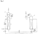
Figur 1 zeigt eine zur Durchführung des erfindungsgemäßen Verfahrens geeignete Anlage. -
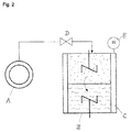
Figur 2 zeigt eine schematische Darstellung einer Doppelrührzelle, die zur Bestimmung der relativen Absorptionsraten verschiedener Absorptionsmittel dient. - In
Figur 1 haben die verwendeten Bezugszeichen folgende Bedeutung: - 1
- = Rauchgas
- 2
- = An Kohlendioxid verarmtes Rauchgas
- 3
- = Abgetrenntes Kohlendioxid
- A
- = Absorptionskolonne
- B
- = Wasserwäsche
- C
- = Absorption
- D
- = Kühler
- E
- = Kühler
- F
- = Pumpe
- G
- = Pumpe
- H
- = Desorptionskolonne
- I
- = Wärmetauscher
- J
- = Verdampfer (Reboiler)
- K
- = Kondensator
- Gemäß
Figur 1 wird Rauchgas 1 in den unteren Teil der Absorptionskolonne A geleitet und im Gegenstrom mit dem Absorptionsmittel in Kontakt gebracht. Das an Kohlendioxid verarmte Rauchgas wird im oberen Teil der Absorptionskolonne mit Wasser gewaschen und über Kopf als Strom 2 aus der Kolonne geführt. Das mit Kohlendioxid beladene Absorptionsmittel wird am Boden der Absorptionskolonne A entnommen und über die Pumpe G und dem Wärmetauscher I in die Desorptionskolonne H geführt. Im unteren Teil der Desorptionskolonne wird das beladene Absorptionsmittel über den Verdampfer J erwärmt. Durch die Temperaturerhöhung geht ein Teil des absorbierten Kohlendioxids wieder in die Gasphase über. Diese wird am Kopf der Desorptionskolonne H abgeführt und im Kondensator K abgekühlt. Auskondensiertes Absorptionsmittel wird über den Kopf wieder zurückgeführt. Das gasförmige Kohlendioxid wird als Strom 3 entnommen. Das regenerierte Absorptionsmittel wird über die Pumpe F und dem Kühler E wieder zur Absorptionskolonne A rückgeführt. - In der
Figur 2 haben verwendeten Bezugszeichen folgende Bedeutung: - A
- = Kohlendioxid-Vorratsbehälter
- B
- = Doppelrührzelle
- C
- = Thermostatierung
- D
- = Dosierventil
- E
- = Druckmeßgerät
- In der Doppelrührzelle B liegt eine untere flüssige Phase des zu testenden Absorptionsmittels vor, die über eine Phasengrenzfläche mit der darüberliegenden Gasphase in Kontakt steht. Flüssig- und Gasphase sind jeweils mit einem Rührer durchmischbar. Die Doppelrührzelle B ist über das Dosierventil D mit einem Kohlendioxid-Vorratsbehälter verbunden. Der Druck in der Doppelrührzelle B kann mit dem Druckmeßgerät E bestimmt werden. Bei der Messung wird der Kohlendioxid-Volumenstrom aufgezeichnet, der sich einstellt, um einen vorgegebenen Druck in der Doppelrührzelle B einzuhalten.
- In den Beispielen werden folgende Abkürzungen verwendet:
- MEA = Monoethanolamin
- MDEA = Methyldiethanolamin
- TEDA = Triethylendiamin
- 1-HEPi = 1-Hydroxyethylpiperidin
- PIP = Piperazin
- MPE = 1-Methyl-2-pyrrolidinethanol
- AC = Aktivkohle
- Zur Bestimmung der Kohlendioxid-Kreislaufkapazität und des Regenerationsbedarfs wurden Laborversuche mit verschiedenen, mit Kohlendioxid beladenen Absorptionsmitteln durchgeführt. Als Vergleichsbasis dient eine 30 Gew.-%ige Lösung von Monoethanolamin in Wasser sowie ein mit Piperazin aktiviertes Methyldiethanolamin-Lösungsmittel.
- Zur Ermittelung der relativen Kreislaufkapazität und der Abschätzung des relativen Dampfmengenbedarfs zur Regeneration des Absorptionsmittels wurden die Gleichgewichtsbeladungen von Kohlendioxid im Absorptionsmittel in Abhängigkeit vom Kohlendioxid-Partialdruck bei 40 (für Absorbersumpf) und 120°C (für Desorbersumpf) bestimmt. Diese Messungen wurden für alle in der Tabelle 1 aufgeführten Systeme durchgeführt. Zur Bestimmung der Gleichgewichtsbeladung wurde ein Glasdruckgefäß mit einem Volumen von ca. 100 cm3 eingesetzt. In diesem wurde eine definierte Menge des Absorptionsmittel vorgelegt, das Gefäß evakuiert, und bei konstanter Temperatur Kohlendioxid stufenweise über ein definiertes Gasvolumen zudosiert. Die in der Flüssigphase gelöste Menge Kohlendioxid wurde unter Berücksichtigung der Gasraumkorrektur durch die darüberstehende Gasphase berechnet.
- Für die Abschätzungen der Kreislaufkapazität des Absorptionsmittels wurden folgende Annahmen gemacht:
- 1. Der Absorber wird bei einem Gesamtdruck von einem bar mit einem Kohlendioxid-haltigen Rauchgas mit einem Kohlendioxid-Partialdruck von 130 hPa (entspricht in etwa 13 Vol.-% Kohlendioxid im Rauchgas bei Atmosphärendruck) beaufschlagt.
- 2. Im Absorbersumpf herrscht eine Temperatur von 40°C.
- 3. Bei der Regeneration herrscht im Desorbersumpf eine Temperatur von 120°C.
- 4. Im Absorbersumpf wird ein Gleichgewichtszustand erreicht. Der Kohlendioxid-Gleichgewichtspartialdruck ist somit gleich dem Feedgas-Partialdruck von 130 hPa.
- 5. Bei der Desorption herrscht ein Kohlendioxid-Partialdruck von 100 hPa im Desorbersumpf.
- 6. Bei der Desorption wird ein Gleichgewichtszustand erreicht.
- Die Kapazität des Absorptionsmittels wurde aus der Beladung (in Nm3 Kohlendioxid / t Absorptionsmittel) am Schnittpunkt der 40°C-Gleichgewichtskurve mit der Linie des konstanten Feedgas-Kohlendioxid-Partialdruckes von 13 kPa (beladene Lösung am Absorbersumpf im Gleichgewicht) und aus der Beladung am Schnittpunkt der 120°C-Gleichgewichtskurve mit der Linie des konstanten Partialdrucks von 100 hPa (regenerierte Lösung am Desorbersumpf im Gleichgewicht) ermittelt. Die Differenz beider Beladungen ist die Kreislaufkapazität des jeweiligen Lösungsmittels. Eine große Kapazität bedeutet, dass weniger Lösungsmittel im Kreis gefahren werden muss und damit die Apparate wie beispielsweise Pumpen, Wärmetauscher aber auch Rohrleitungen kleiner dimensioniert werden können. Weiterhin beeinflusst die Umlaufmenge auch die zum Regenerieren notwendige Energie.
- Ein weiteres Maß für die Anwendungseigenschaften eines Absorptionsmittels ist die Steigung der Arbeitsgeraden im McCabe-Thiele-Diagramm des Desorbers. Für die Verhältnisse im Sumpf des Desorbers liegt die Arbeitsgerade in der Regel sehr nahe bei der Gleichgewichtslinie, so dass die Steigung der Gleichgewichtskurve näherungsweise der Steigung der Arbeitsgeraden gleichgesetzt werden kann. Bei konstanter Flüssigkeitsbelastung ist zur Regeneration eines Absorptionsmittels mit einer großen Steigung der Gleichgewichtskurve eine geringere Strippdampfmenge erforderlich. Der Energiebedarf zur Erzeugung des Strippdampfes trägt wesentlich zum Gesamtenergiebedarf des Kohlendioxid-Absorptionsprozesses bei.
- Zweckmäßigerweise gibt man den Reziprokwert der Steigung an, da dieser direkt proportional zur benötigten Dampfmenge pro Kilogramm Absorptionsmittel ist. Dividiert man den Reziprokwert durch die Kapazität des Absorptionsmittels, so erhält man einen Vergleichswert, der direkt eine relative Aussage über die benötigte Dampfmenge pro absorbierter Kohlendioxid-Menge ermöglicht.
- In Tabelle 1 sind für erfindungsgemäße Absorptionsmittel die Werte der relativen Kreislaufkapazität und des relativen Dampfmengenbedarfs dargestellt (normiert auf MEA). Im Vergleich zu 30 Gew.-% MEA ist die relative Kreislaufkapazität beim Einsatz eines erfindungsgemäßen Lösungsmittel zwischen 3 und 46 % größer. Der relative Dampfmengenbedarf ist für die erfindungsgemäße Lösungsmittel signifikant niedriger als für das Vergleichslösungsmittel MEA, was in der großtechnischen Anwendung ein enormes Sparpotenzial darstellt. Das Vergleichsabsorptionsmittel aus MDEA und Piperazin zeigt hinsichtlich der Kapazität und des Energiebedarfes ebenfalls eine deutliche Verbesserung gegenüber Monoethanolamin.
- Zur Bestimmung der Stofftransportgeschwindigkeit des Kohlendioxids aus dem Gasstrom in das Absorptionsmittel wurden Messungen in einer Doppelrührzelle (
Figur 2 ) durchgeführt. Die Stofftransportgeschwindigkeit setzt sich bei einer Reaktivabsorption sowohl aus dem physikalischen Stofftransport als auch der Reaktionskinetik zwischen dem Absorptionsmittel und dem Kohlendioxid zusammen. Diese beiden Einflussgrößen können in der Doppelrührzelle als summarischer Parameter gemessen werden. Als Vergleichsbasen dienten 31,2 Gew.-% Monoethanolamin (MEA) in Wasser, sowie 25 Gew.-% Methyldiethanolamin mit 15 Gew.-% Piperazin in Wasser. Die erfindungsgemäßen Absorptionsmittel enthielten 15 bis 30 Gew.-% des zyklischen tertiären Amines und 15 Gew.-% Piperazin. - Die Doppelrührzelle hatte einen inneren Durchmesser von 85 mm und ein Volumen von 509 ml. Die Zelle wurde während der Versuche auf 50°C thermostatisiert. Zur Durchmischung der Gas- und Flüssigphase war die Zelle gemäß der schematischen Darstellung mit zwei Rührern ausgerüstet. Vor Beginn des Versuches wurde die Doppelrührzelle evakuiert. Ein definiertes Volumen des entgasten Absorptionsmittels wurde in die Doppelrührzelle gefördert und auf 50°C thermostatisiert. Während des Aufheizens des unbeladenen Absorptionsmittels wurden bereits die Rührer eingeschaltet. Die Rührerdrehzahl wurde so gewählt, dass sich eine ebene Phasengrenzfläche zwischen der Flüssigphase und Gasphase einstellt. Eine Wellenbildung an der Phasengrenzfläche ist zu vermeiden, da hierdurch keine definierte Phasengrenzfläche vorliegen würde. Nachdem die gewünschte Versuchstemperatur erreicht wurde, wurde über ein Regelventil Kohlendioxid in den Reaktor eingeleitet. Der Volumenstrom wurde so geregelt, dass in der Doppelrührzelle während des Versuchs ein konstanter Druck von 50 hPa abs (entspricht Kohlendioxid-Partialdruck) herrschte. Mit zunehmender Versuchsdauer nahm der Volumenstrom an Kohlendioxid ab, da das Absorptionsmittel mit der Zeit gesättigt wurde und somit die Absorptionsrate abnahm. Der Volumenstrom an Kohlendioxid, der in die Doppelrührzelle strömte, wurde über die gesamte Versuchsdauer registriert. Das Versuchsende war erreicht sobald kein Kohlendioxid mehr in die Doppelrührzelle strömte. Das Absorptionsmittel lag am Versuchsende nahezu im Gleichgewichtszustand vor.
- Zur Auswertung der Versuche wurde die Absorptionsrate in mol CO2 / (m3 Absorptionsmittel · min) in Abhängigkeit von der Beladung des Absorptionsmittels bestimmt. Die Absorptionsrate wurde aus dem registrierten Volumenstrom an Kohlendioxid und dem eingefüllten Volumen an Absorptionsmittel berechnet. Die Beladung wurde aus der akkumulierten Menge an Kohlendioxid, die der Doppelrührzelle zugeführt wurde, und der eingefüllten Masse an Absorptionsmittel bestimmt.
- In Tabelle 2 sind die mittleren relativen Absorptionsraten von verschiedenen Absorptionsmitteln, normiert auf die mittlere Absorptionsrate von 25 Gew.-% MDEA/15 Gew.-% PIP, dargestellt. Die mittlere Absorptionsrate wurde wie folgt ermittelt: Ausgehend von der maximalen Beladung des Absorptionsmittel (nahezu Gleichgewichtszustand bei einem CO2-Partialdruck von 50 hPa und einer Temperatur von 50°C) wurden die Absorptionsraten bei 75, 50 und 20 % Beladung der maximalen Beladung bestimmt und gemittelt. Absorptionsraten bei kleiner 20 % Beladung werden bei der Mittelung nicht berücksichtigt, da das Absorptionsmittel im technischen Prozess mit einer Restbeladung an CO2 in den Absorptionsapparat gelangt.
- Im Vergleich zu dem MDEA/PIP-Absorptionsmittel sind die Absorptionsraten der erfindungsgemäßen Absorptionsmittel größer, teilweise sogar größer als die von Monoethanolamin, das sehr reaktiv gegenüber CO2 ist.
- Für das Absorptionsmittel bestehend aus 15 Gew.-% PIP und 25 Gew.-% TEDA und 0,1 Gew.-% Aktivkohle konnte eine weitere Erhöhung der Absorptionsraten im Vergleich zu einem Absorptionsmittel bestehend aus 15 Gew.-% PIP und 25 Gew.- TEDA beobachtet werden. Durch die Zugabe der Aktivkohle hat sich die Absorptionsrate um mehr als den Faktor 2 erhöht.
- Unter Berücksichtigung von Beispiel 1 wird deutlich, dass die erfindungsgemäßen Absorptionsmittel bei Betrachtung aller drei Kriterien - zyklische Kapazität, Regenerationsbedarf und Absorptionsrate - sowohl gegenüber MEA als auch der Mischung bestehend aus MDEA und PIP Vorteile aufzeigt. So würde eine wässrige MEA-Lösung zwar eine sehr hohe Absorptionsrate aufweisen, aber ebenso auch einen sehr hohen Energiebedarf bei der Regeneration. Umgekehrt würde eine wässrige Mischung aus MDEA und PIP nur eine unzureichend niedrige Absorptionsrate aufweise, was bei der technischen Umsetzung eine wesentlich größere Absorberkolonne erfordern würde. Die Beispiele 1 und 2 belegen, dass durch den Einsatz einer entsprechenden Mischung überraschenderweise ein sehr ausgewogenes Absorptionsmittel erhalten wird, welches sowohl eine hohe Absorptionsrate aufweist als auch einen sehr niedrigen Energiebedarf zur Regeneration erfordert.
- Zur Untersuchung der Sauerstoffstabilität der wässrigen Aminmischungen wurden die im Folgenden beschriebenen Untersuchungen durchgeführt. In einem durch ein Ölbad beheizbaren Autoklaven wurden etwa 150 ml der Absorptionsmittel vorgelegt. Bei einer Temperatur von 40 °C wurde in diese Probe kontinuierlich ein Gasgemisch (V = 7,5 NI/h) bestehen aus 33 Vol% CO2, 14 Vol% Sauerstoff und 53 Vol% Stickstoff geleitet, zusätzlich wurde die Flüssigkeit mit 10 NI/h Stickstoff überdeckt. Zur Verteilung des Gases in die gesamte Flüssigkeit wurde eine Metallfritte verwendet. Zur Verhinderung von Absorptionsverlusten befindet sich oberhalb des Autoklaven ein Rückflusskühler, der bei einer Temperatur von 4 °C betrieben wird. Die Konzentration an CO2 am Austritt des Rückflusskühlers wird mittels einer IR-Sonde bestimmt. Sobald das Absorptionsmittel vollständig mit CO2 beladenen ist, steigt die mit der IR-Sonde gemessene CO2-Konzentration sprunghaft an. Die Zufuhr an Gas wird gestoppt und die Probe wird auf 100 °C aufgeheizt. Zum Strippen der Probe wird nun ausschließlich Stickstoff in das Absorptionsmittel geleitet. Während des Strippens der Probe wird die Konzentration am Austritt des Rückflusskühlers ebenfalls mit der IR-Sonde überwacht. Sobald die CO2-Konzentration nahezu 0 beträgt, wird der Inhalt des Autoklaven auf 40 °C abgekühlt und der Zyklus wiederholt sich von neuem. Durch diesen Zyklus wird der Absorptionsvorgang und Desorptionsvorgang nachgestellt. Nach jedem Zyklus wird eine kleine Probe des Absorptionsmittels entnommen und mittels Gaschromatographie auf seine Bestandteile (Amingehalte) untersucht. Diese Versuche werden über mehrere hundert Stunden durchgeführt und erlauben somit eine Aussage über die Stabilität des Absorptionsmittels. Es wird somit ein Summenparameter für die Stabilität ermittelt, da sowohl die Sauerstoffstabilität, die thermische Stabilität als auch die Stabilität des Amins gegenüber CO2 bestimmt wird.
- Für die in Tabelle 3 aufgeführten Beispiele wurde jeweils eine Versuchsreihe durchgeführt, bei der mindestens 2 Autoklaven parallel betrieben wurde. Ein Autoklav wurde mit einer 30 Gew.-% Monoethanolaminlösung betrieben, der zweite mit einem zu testenden Absorptionsmittel. Als Maß wurde der relative Aminverlust der Aminverbindung A) im Vergleich zum Verlust an MEA dargestellt. D.h. bei 100 % ist die Aminverbindung A) genauso stabil wie MEA bzw. bei 10 % um den Faktor 10 stabiler.
- Die Stabilität von Piperazin wurde bereits von Freeman et al. untersucht. Die Ergebnisse sind u.a. beschriebenen in Freeman, S. A.; Dugas, R. van Wagener, D., Nguyen, T.; Rochelle G.T.: Carbon dioxide capture with concentrated, aqueous piperazine, GHGT-9, 2008 Nov 16-20, Washington DC, USA. In diesen Untersuchungen wurde gefunden, dass Piperazin im Vergleich zu Monoethanolamin 4-mal stabiler gegenüber Sauerstoff ist, und im Vergleich zu Monoethanolamin keine thermische Degradation zeigt.
Tabelle 1: Relative Kreislaufkapazität und Dampfmengenbedarf normiert auf MEA Zusammensetzung in Gew.-% relative zyklische Kapazität relativer Dampfmengenbedarf 30 % MEA 100% 100% 25% MDEA + 15 % PIP 116% 48% 15 % TEDA + 15 PIP 103% 60% 25 % TEDA + 15 % PIP 124% 52% 15 % 1-HEPi + 15 % PIP 108% 61% 30 % 1-HEPi + 15 % PIP 146% 39% 30 % 2-HEPi + 15 % PIP 135% 73% 30% MPE 15% PIP 143% 45% Tabelle 2: Relative mittlere Absorptionsrate von verschiedenen Absorptionsmittel normiert auf 25 Gew.-% MDEA und 15 Gew.-% PIP Zusammensetzung in Gew.-% mittlere relative Absorptionsrate 30 % MEA 181% 25 % MDEA + 15 % PIP 100% 30 % 1-HEPi + 15 % PIP 156% 15 % 1-HEPi + 15 % PIP 203% 15 % TEDA + 15 % PIP 167% 25 % TEDA + 15 % PIP 112% 25 % TEDA + 15 % PIP + 0,1 % AC* 253% * Norit SA Super (BET-Oberfläche 1150 m2/g) Tabelle 3: Relative Stabilität von tertiären zyklischen Aminen im Vergleich zu MEA Tertiäres Amin Versuchsdauer Stabilität = relativer Aminverlust im Vergleich zu MEA [h] - 1-HEPi 650 11% TEDA 350 3% MPE 300 47%
Die zyklische Aminverbindung A) weist vorzugsweise eine Molmasse von 250 g/mol oder weniger auf. Die zyklische Aminverbindung B) weist vorzugsweise eine Molmasse von 200 g/mol oder weniger auf.
Claims (12)
- Absorptionsmittel zur Entfernung saurer Gase aus einem Fluidstrom, umfassend eine wässrige LösungA) wenigstens einer zyklischen Aminverbindung mit ausschließlich tertiären Amingruppen, undB) wenigstens einer zyklischen Aminverbindung mit wenigstens einer sterisch ungehinderten sekundären Amingruppe,wobei die Gesamtkonzentration von A) + B) 10 bis 60 Gew.-% beträgt.
- Absorptionsmittel nach Anspruch 1, wobei das Gewichtsverhältnis von A) zu B) 0,5 bis 4 beträgt.
- Absorptionsmittel nach einem der vorhergehenden Ansprüche, wobei die zyklische Aminverbindung A) einen 5- bis 7-gliedrigen Ring der allgemeinen Formel I aufweist,

oder für den Fall, dass m für 2 steht, zwei Reste R gemeinsam eine C2-C3-Alkyfenbrücke bilden können; R' für H, C1-C4-Alkyl oder C2-C4-Hydroxyalkyl steht; R" für H oder C1-C4-Alkyl steht; Z für eine Bindung oder C1-C6-Alkylen steht. - Absorptionsmittel nach Anspruch 3, wobei die zyklische Aminverbindung A) ausgewählt ist unter:Triethylendiamin, 1-Hydroxyethylpiperidin, Bis(hydroxyethyl)piperazin, N,N'-Dimethytpiperazin und 1-Methyl-2-pyrrolidinethanol.
- Absorptionsmittel nach einem der vorhergehenden Ansprüche, wobei die zyklische Aminverbindung B) die allgemeine Formel II aufweist

- Absorptionsmittel nach Anspruch 5, wobei die zyklische Aminverbindung B) ausgewählt ist unter Piperazin, Homopiperazin, 1-Hydroxyethyl-piperazin, 4-Hydroxyethyl-piperidin, 1-Methylpiperazin und 2-Methylpiperazin.
- Absorptionsmittel nach einem der vorhergehenden Ansprüche, umfassend eine wässrige Lösung vonA) 1-Hydroxyethyl-piperidin und/oder Triethylendiamin; undB) Piperazin.
- Verfahren zum Entfernen saurer Gase aus einem Fluidstrom, wobei man den Fluidstrom mit einem Absorptionsmittel nach einem der vorhergehenden Ansprüche in Kontakt bringt.
- Verfahren nach Anspruch 8, wobei der Partialdruck von Kohlendioxid im Fluidstrom weniger als 500 mbar beträgt.
- Verfahren nach Anspruch 8 oder 9, wobei der Fluidstroma) der Oxidation organischer Substanzen.b) der Kompostierung oder Lagerung organischer Substanzen enthaltender Abfallstoffe, oderc) der bakteriellen Zersetzung organischer Substanzenentstammt
- Verfahren nach einem der Ansprüche 8 bis 10, wobei man den Fluidstrom in einer im Gegenstrom betriebenen Waschkolonne in Gegenwart von im Inneren der Waschkolonne vorhandener Aktivkohle mit dem Absorptionsmittel in Kontakt bringt, wobei sich im Inneren der Waschkolonne eine diskontinuierliche flüssige Absorptionsmittelphase ausbildet.
- Verfahren nach einem der Ansprüche 8 bis 11, wobei man das beladene Absorptionsmittel durcha) Erwärmung,b) Entspannung,c) Strippen mit einem inerten Fluidoder eine Kombination zweier oder alter dieser Maßnahmen regeneriert.
Priority Applications (2)
| Application Number | Priority Date | Filing Date | Title |
|---|---|---|---|
| EP10701558.8A EP2391435B1 (de) | 2009-02-02 | 2010-02-01 | Zyklische amine enthaltendes absorptionsmittel zum entfernen saurer gase |
| PL10701558T PL2391435T3 (pl) | 2009-02-02 | 2010-02-01 | Absorbent zawierający cykliczne aminy do usuwania kwaśnych gazów |
Applications Claiming Priority (4)
| Application Number | Priority Date | Filing Date | Title |
|---|---|---|---|
| EP09151885 | 2009-02-02 | ||
| EP09159104 | 2009-04-29 | ||
| EP10701558.8A EP2391435B1 (de) | 2009-02-02 | 2010-02-01 | Zyklische amine enthaltendes absorptionsmittel zum entfernen saurer gase |
| PCT/EP2010/051204 WO2010086449A1 (de) | 2009-02-02 | 2010-02-01 | Zyklische amine enthaltendes absorptionsmittel zum entfernen saurer gase |
Publications (2)
| Publication Number | Publication Date |
|---|---|
| EP2391435A1 EP2391435A1 (de) | 2011-12-07 |
| EP2391435B1 true EP2391435B1 (de) | 2013-12-04 |
Family
ID=41800511
Family Applications (1)
| Application Number | Title | Priority Date | Filing Date |
|---|---|---|---|
| EP10701558.8A Active EP2391435B1 (de) | 2009-02-02 | 2010-02-01 | Zyklische amine enthaltendes absorptionsmittel zum entfernen saurer gase |
Country Status (11)
| Country | Link |
|---|---|
| US (2) | US8603226B2 (de) |
| EP (1) | EP2391435B1 (de) |
| JP (1) | JP5679995B2 (de) |
| CN (2) | CN103961977A (de) |
| AU (1) | AU2010209661B2 (de) |
| CA (1) | CA2750460C (de) |
| DK (1) | DK2391435T3 (de) |
| ES (1) | ES2443307T3 (de) |
| PL (1) | PL2391435T3 (de) |
| PT (1) | PT2391435E (de) |
| WO (1) | WO2010086449A1 (de) |
Families Citing this family (45)
| Publication number | Priority date | Publication date | Assignee | Title |
|---|---|---|---|---|
| JO3041B1 (ar) * | 2008-07-25 | 2016-09-05 | Galapagos Nv | مركبات جديدة مفيدة لمعالجة الأمراض التنكسية والالتهابية |
| BRPI1012049A2 (pt) | 2009-05-26 | 2019-04-16 | Basf Se | "processo para remover dióxido de carbono de um fluido, e, instalação para remover dióxido de carbono de um fluido" |
| US8425849B2 (en) | 2009-10-19 | 2013-04-23 | Mitsubishi Heavy Industries, Ltd. | Reclaiming apparatus |
| US8795618B2 (en) * | 2010-03-26 | 2014-08-05 | Babcock & Wilcox Power Generation Group, Inc. | Chemical compounds for the removal of carbon dioxide from gases |
| WO2011121633A1 (ja) * | 2010-03-29 | 2011-10-06 | 株式会社 東芝 | 酸性ガス吸収剤、酸性ガス除去装置および酸性ガス除去方法 |
| US8814989B2 (en) | 2010-05-18 | 2014-08-26 | Basf Se | Process for removing carbon dioxide (CO2) from a cycle gas system |
| PT2691163E (pt) * | 2011-03-31 | 2015-06-25 | Basf Se | Retenção de aminas na remoção de gases ácidos através de meios absorventes de aminas |
| JP5659084B2 (ja) * | 2011-05-30 | 2015-01-28 | 株式会社東芝 | 酸性ガス吸収剤、酸性ガス除去方法および酸性ガス除去装置 |
| JP5755047B2 (ja) * | 2011-06-22 | 2015-07-29 | 三菱重工業株式会社 | 排ガス処理システム及び排ガス処理方法 |
| RU2488430C2 (ru) * | 2011-07-14 | 2013-07-27 | Общество с ограниченной ответственностью "Петон" | Способ очистки сжиженного углеводородного газа от диоксида углерода |
| JP2013158718A (ja) * | 2012-02-06 | 2013-08-19 | Ihi Corp | 二酸化炭素吸収液及びその調製方法 |
| CA2868895C (en) * | 2012-03-29 | 2018-08-14 | Htc Purenergy Inc. | System and process for reclaiming single and mixed amine solvents |
| MX345138B (es) * | 2012-06-15 | 2017-01-18 | Dow Global Technologies Llc | Proceso para el tratamiento de hidrocarburos licuados usando compuestos de 3-(piperazin-1-il)propan-1, 2-diol. |
| CN102794095B (zh) * | 2012-09-12 | 2014-11-05 | 湖南大学 | 三(2-氨乙基)胺作为二氧化碳吸收剂方面的应用 |
| US9266102B2 (en) | 2013-03-29 | 2016-02-23 | The University Of Kentucky Research Foundation | Catalysts and methods of increasing mass transfer rate of acid gas scrubbing solvents |
| US9409125B2 (en) | 2013-03-29 | 2016-08-09 | The University Of Kentucky Research Foundation | Method of increasing mass transfer rate of acid gas scrubbing solvents |
| US9468883B2 (en) | 2013-03-29 | 2016-10-18 | The University Of Kentucky Research Foundation | Solvent and method for removal of an acid gas from a fluid stream |
| KR102165175B1 (ko) | 2013-10-10 | 2020-10-13 | 삼성전자주식회사 | 리튬 이차 전지용 전해질 및 이를 포함하는 리튬 이차 전지 |
| JP5984776B2 (ja) * | 2013-10-15 | 2016-09-06 | 三菱重工業株式会社 | 複合アミン吸収液、co2又はh2s又はその双方の除去装置及び方法 |
| EP3148678A4 (de) * | 2014-06-02 | 2018-04-25 | Board of Regents, The University of Texas System | Thermisch stabile amine zur co2-erfassung |
| RU2597081C2 (ru) * | 2014-12-29 | 2016-09-10 | Игорь Анатольевич Мнушкин | Способ комплексного извлечения ценных примесей из природного гелийсодержащего углеводородного газа с повышенным содержанием азота |
| DE102015212749A1 (de) | 2015-07-08 | 2017-01-12 | Evonik Degussa Gmbh | Verfahren zur Entfeuchtung von feuchten Gasgemischen |
| CA3000274C (en) | 2015-09-29 | 2023-08-01 | Basf Se | Cyclic amine for selectively removing hydrogen sulphide |
| DE102016210478A1 (de) | 2016-06-14 | 2017-12-14 | Evonik Degussa Gmbh | Verfahren zur Entfeuchtung von feuchten Gasgemischen |
| EP3257568B1 (de) | 2016-06-14 | 2019-09-18 | Evonik Degussa GmbH | Verfahren zur entfeuchtung von feuchten gasgemischen mit ionischen flüssigkeiten |
| DE102016210484A1 (de) | 2016-06-14 | 2017-12-14 | Evonik Degussa Gmbh | Verfahren zur Entfeuchtung von feuchten Gasgemischen |
| DE102016210483A1 (de) | 2016-06-14 | 2017-12-14 | Evonik Degussa Gmbh | Verfahren und Absorptionsmittel zur Entfeuchtung von feuchten Gasgemischen |
| DE102016210481B3 (de) | 2016-06-14 | 2017-06-08 | Evonik Degussa Gmbh | Verfahren zum Reinigen einer ionischen Flüssigkeit |
| RU2648077C9 (ru) * | 2017-08-29 | 2018-07-04 | Игорь Анатольевич Мнушкин | Газохимический комплекс |
| CN109513312A (zh) * | 2017-09-18 | 2019-03-26 | 中国石化扬子石油化工有限公司 | 一种利用无水脱硫溶剂脱除混合气中硫化氢的方法 |
| US11207634B2 (en) | 2018-07-02 | 2021-12-28 | University Of Kentucky Research Foundation | Apparatus and method for recovering an amine solvent from an acid gas stream |
| CN112638849B (zh) | 2018-09-04 | 2023-11-24 | 巴斯夫欧洲公司 | 在没有二氧化碳排放下由合成气制备甲醇的方法 |
| CN109529544A (zh) * | 2018-11-30 | 2019-03-29 | 攀钢集团攀枝花钢铁研究院有限公司 | 脱二氧化硫组合物、制备方法及脱硫方法 |
| US12297167B2 (en) | 2020-01-22 | 2025-05-13 | Basf Se | Process for preparing methanol from carbon dioxide and hydrogen with quantitative carbon dioxide utilization |
| AU2021214918A1 (en) * | 2020-01-29 | 2022-07-28 | Research Triangle Institute | Methods and systems for reducing the concentration of amine in wash liquid used in industrial processing |
| US12485382B2 (en) * | 2020-12-16 | 2025-12-02 | Dow Global Technologies LLCmi | Aqueous absorption medium for removal of acid gases |
| CN113371957A (zh) * | 2021-05-13 | 2021-09-10 | 西北矿冶研究院 | 一种基于微生物电解池处理剩余污泥的方法 |
| CN113318571A (zh) * | 2021-05-27 | 2021-08-31 | 华侨大学 | 一种用于捕集co2的双相吸收剂及其应用 |
| CN115970443A (zh) * | 2021-10-14 | 2023-04-18 | 中石化南京化工研究院有限公司 | 一种从低含硫气体中脱除h2s的吸收液 |
| JP2023124995A (ja) * | 2022-02-28 | 2023-09-07 | 東ソー株式会社 | 二酸化炭素分離用アミン組成物 |
| CN115253600B (zh) * | 2022-08-08 | 2024-03-05 | 华北电力大学(保定) | 一种具有良好循环解吸稳定性、低腐蚀性的相变吸收剂的制备与应用 |
| CN121219058A (zh) | 2023-05-16 | 2025-12-26 | 巴斯夫欧洲公司 | 用于生产脱酸流体流的方法、用于使流体流脱酸的设备以及热泵用于使流体流脱酸的用途 |
| WO2025040491A1 (en) | 2023-08-22 | 2025-02-27 | Basf Se | Method and apparatus for the manufacture of a treated gas with reduced solvent losses |
| CN118454438B (zh) * | 2024-05-16 | 2024-11-19 | 绍兴兴欣新材料股份有限公司 | 二氧化碳复合吸收剂 |
| CN121243978B (zh) * | 2025-12-08 | 2026-03-10 | 华东理工大学 | 一种选择性脱除硫化氢的相变吸收剂及其制备方法与应用 |
Family Cites Families (22)
| Publication number | Priority date | Publication date | Assignee | Title |
|---|---|---|---|---|
| US4096085A (en) * | 1976-10-29 | 1978-06-20 | The Dow Chemical Company | Gas scrubbing system |
| US4100257A (en) * | 1977-02-14 | 1978-07-11 | Exxon Research & Engineering Co. | Process and amine-solvent absorbent for removing acidic gases from gaseous mixtures |
| US4477419A (en) * | 1983-03-03 | 1984-10-16 | The Dow Chemical Company | Process for the recovery of CO2 from flue gases |
| EP0558019B2 (de) | 1992-02-27 | 2005-12-14 | The Kansai Electric Power Co., Inc. | Verfahren zur Entfernung von Kohlendioxid aus Verbrennungsabgasen |
| US5603908A (en) * | 1992-09-16 | 1997-02-18 | The Kansai Electric Power Co., Inc. | Process for removing carbon dioxide from combustion gases |
| DE69528785T2 (de) * | 1994-03-18 | 2003-07-03 | Mitsubishi Jukogyo K.K., Tokio/Tokyo | Verfahren zur Entfernung von Schwefelwasserstoff aus Gasen |
| JP3197183B2 (ja) * | 1995-03-16 | 2001-08-13 | 関西電力株式会社 | 燃焼排ガス中の二酸化炭素を除去する方法 |
| US5618506A (en) * | 1994-10-06 | 1997-04-08 | The Kansai Electric Power Co., Inc. | Process for removing carbon dioxide from gases |
| JP3392609B2 (ja) * | 1995-12-01 | 2003-03-31 | 三菱重工業株式会社 | ガス中の炭酸ガスを除去する方法 |
| JP4287915B2 (ja) * | 1997-03-07 | 2009-07-01 | 三菱重工業株式会社 | ガス中の硫化水素の処理方法及びその装置 |
| JP2002102649A (ja) * | 2000-09-28 | 2002-04-09 | Kashiyama Kogyo Kk | ガス処理方法及びガス処理装置 |
| DE10306254A1 (de) * | 2003-02-14 | 2004-08-26 | Basf Ag | Absorptionsmittel und Verfahren zur Entfernung saurer Gase aus Fluiden |
| US7056482B2 (en) * | 2003-06-12 | 2006-06-06 | Cansolv Technologies Inc. | Method for recovery of CO2 from gas streams |
| DE102004011427A1 (de) * | 2004-03-09 | 2005-09-29 | Basf Ag | Absorptionsmittel mit verbesserter Oxidationsbeständigkeit und Verfahren zum Entsäuern von Fluidströmen |
| DE102004011429A1 (de) | 2004-03-09 | 2005-09-29 | Basf Ag | Verfahren zum Entfernen von Kohlendioxid aus Gasströmen mit niedrigen Kohlendioxid-Partialdrücken |
| JP4634384B2 (ja) * | 2005-04-04 | 2011-02-16 | 三菱重工業株式会社 | 吸収液、co2又はh2s又はその双方の除去方法及び装置 |
| EP2001577B1 (de) * | 2006-03-10 | 2013-09-25 | C-Quest Technologies International LLC | Verfahren zur kohlendioxidfixierung |
| EP1998870B2 (de) * | 2006-03-16 | 2015-09-02 | Basf Se | Verfahren zum inkontaktbringen zweier phasen, deren kontakt von wärmeentwicklung begleitet ist |
| DK2026896T3 (en) * | 2006-05-18 | 2016-11-28 | Basf Se | KULDIOXIDABSORPTIONSMIDDEL WITH REDUCED Regeneration ENERGY NEEDS |
| WO2007144372A1 (de) | 2006-06-13 | 2007-12-21 | Basf Se | Entfernung von kohlendioxid aus rauchgasen |
| KR100768383B1 (ko) * | 2006-11-29 | 2007-10-18 | 한국전력공사 | 이산화탄소 분리용 혼합 흡수제 |
| JP5557426B2 (ja) * | 2008-03-07 | 2014-07-23 | 公益財団法人地球環境産業技術研究機構 | ガス中の二酸化炭素を効率的に吸収及び回収する水溶液及び方法 |
-
2010
- 2010-02-01 AU AU2010209661A patent/AU2010209661B2/en active Active
- 2010-02-01 CN CN201410174268.7A patent/CN103961977A/zh active Pending
- 2010-02-01 PT PT107015588T patent/PT2391435E/pt unknown
- 2010-02-01 CA CA2750460A patent/CA2750460C/en active Active
- 2010-02-01 PL PL10701558T patent/PL2391435T3/pl unknown
- 2010-02-01 WO PCT/EP2010/051204 patent/WO2010086449A1/de not_active Ceased
- 2010-02-01 ES ES10701558.8T patent/ES2443307T3/es active Active
- 2010-02-01 CN CN201080006045XA patent/CN102300620A/zh active Pending
- 2010-02-01 JP JP2011546871A patent/JP5679995B2/ja active Active
- 2010-02-01 EP EP10701558.8A patent/EP2391435B1/de active Active
- 2010-02-01 DK DK10701558.8T patent/DK2391435T3/en active
- 2010-02-02 US US12/698,178 patent/US8603226B2/en active Active
-
2013
- 2013-11-19 US US14/083,967 patent/US20140079613A1/en not_active Abandoned
Also Published As
| Publication number | Publication date |
|---|---|
| US20100192770A1 (en) | 2010-08-05 |
| EP2391435A1 (de) | 2011-12-07 |
| JP2012516762A (ja) | 2012-07-26 |
| AU2010209661B2 (en) | 2015-09-17 |
| PL2391435T3 (pl) | 2014-05-30 |
| US8603226B2 (en) | 2013-12-10 |
| ES2443307T3 (es) | 2014-02-18 |
| US20140079613A1 (en) | 2014-03-20 |
| CA2750460A1 (en) | 2010-08-05 |
| CN102300620A (zh) | 2011-12-28 |
| DK2391435T3 (en) | 2014-02-24 |
| JP5679995B2 (ja) | 2015-03-04 |
| WO2010086449A1 (de) | 2010-08-05 |
| PT2391435E (pt) | 2014-01-23 |
| CA2750460C (en) | 2017-01-24 |
| CN103961977A (zh) | 2014-08-06 |
| AU2010209661A1 (en) | 2011-08-25 |
Similar Documents
| Publication | Publication Date | Title |
|---|---|---|
| EP2391435B1 (de) | Zyklische amine enthaltendes absorptionsmittel zum entfernen saurer gase | |
| EP2300127B1 (de) | Absorptionsmittel und verfahren zur entfernung von sauergasen aus fluidströmen, insbesondere aus rauchgasen | |
| EP1725320B1 (de) | Verfahren zum entfernen von kohlendioxid aus gasströmen mit niedrigen kohlendioxid-partialdrücken | |
| EP2300128B1 (de) | Absorptionsmittel und verfahren zur entfernung von sauergasen aus fluidströmen, insbesondere aus rauchgasen | |
| EP1940534B1 (de) | Absorptionsmittel und verfahren zum entfernen von kohlendioxid aus gasströmen | |
| EP2892633B1 (de) | Verfahren zur abtrennung von sauergasen aus einem wasserhaltigen fluidstrom | |
| EP2445612A1 (de) | Entfernung saurer gase mittels eines ein stripphilfsmittel enthaltenden absorptionsmittels | |
| EP1582250B2 (de) | Absorptionsmittel mit verbesserter Oxidationsbeständigkeit und Verfahren zum Entsäuern von Fluidströmen | |
| EP2059327B1 (de) | Entfernung von kohlendioxid aus verbrennungsabgasen | |
| EP1599274B1 (de) | Absorptionsmittel und verfahren zur entfernung saurer gase aus fluiden | |
| EP2032234B1 (de) | Entfernung von kohlendioxid aus rauchgasen | |
| EP1725321A1 (de) | Verfahren zum entfernen von kohlendioxid aus rauchgasen | |
| EP2780098A1 (de) | Verfahren und vorrichtung zur abtrennung von sauren gasen aus einer gasmischung | |
| EP3186222B1 (de) | Diamin mit tert-alkylamino- und primärer aminogruppe zur verwendung in der gaswäsche | |
| DE2804418A1 (de) | Verfahren zur entfernung saurer gase aus einer normalerweise gasfoermigen mischung | |
| EP3185990B1 (de) | Entfernung von kohlendioxid aus einem fluidstrom mit einem tert-butylamin und einem aktivator | |
| EP2532414A1 (de) | Verfahren zur Absorption von CO2 aus einer Gasmischung | |
| WO2008145658A1 (de) | Absorptionsmittel zum entfernen von sauren gasen, umfassend eine basische aminocarbonsäure | |
| EP2691163B1 (de) | Rückhaltung von aminen bei der entfernung saurer gase mittels amin-absorptionsmitteln |
Legal Events
| Date | Code | Title | Description |
|---|---|---|---|
| PUAI | Public reference made under article 153(3) epc to a published international application that has entered the european phase |
Free format text: ORIGINAL CODE: 0009012 |
|
| 17P | Request for examination filed |
Effective date: 20110902 |
|
| AK | Designated contracting states |
Kind code of ref document: A1 Designated state(s): AT BE BG CH CY CZ DE DK EE ES FI FR GB GR HR HU IE IS IT LI LT LU LV MC MK MT NL NO PL PT RO SE SI SK SM TR |
|
| DAX | Request for extension of the european patent (deleted) | ||
| 17Q | First examination report despatched |
Effective date: 20130122 |
|
| GRAP | Despatch of communication of intention to grant a patent |
Free format text: ORIGINAL CODE: EPIDOSNIGR1 |
|
| INTG | Intention to grant announced |
Effective date: 20130801 |
|
| GRAS | Grant fee paid |
Free format text: ORIGINAL CODE: EPIDOSNIGR3 |
|
| GRAA | (expected) grant |
Free format text: ORIGINAL CODE: 0009210 |
|
| AK | Designated contracting states |
Kind code of ref document: B1 Designated state(s): AT BE BG CH CY CZ DE DK EE ES FI FR GB GR HR HU IE IS IT LI LT LU LV MC MK MT NL NO PL PT RO SE SI SK SM TR |
|
| REG | Reference to a national code |
Ref country code: GB Ref legal event code: FG4D Free format text: NOT ENGLISH |
|
| REG | Reference to a national code |
Ref country code: CH Ref legal event code: EP |
|
| REG | Reference to a national code |
Ref country code: IE Ref legal event code: FG4D Free format text: LANGUAGE OF EP DOCUMENT: GERMAN Ref country code: AT Ref legal event code: REF Ref document number: 643279 Country of ref document: AT Kind code of ref document: T Effective date: 20140115 |
|
| REG | Reference to a national code |
Ref country code: PT Ref legal event code: SC4A Free format text: AVAILABILITY OF NATIONAL TRANSLATION Effective date: 20140116 |
|
| REG | Reference to a national code |
Ref country code: DE Ref legal event code: R096 Ref document number: 502010005549 Country of ref document: DE Effective date: 20140130 |
|
| REG | Reference to a national code |
Ref country code: ES Ref legal event code: FG2A Ref document number: 2443307 Country of ref document: ES Kind code of ref document: T3 Effective date: 20140218 |
|
| REG | Reference to a national code |
Ref country code: RO Ref legal event code: EPE |
|
| REG | Reference to a national code |
Ref country code: DK Ref legal event code: T3 Effective date: 20140221 |
|
| REG | Reference to a national code |
Ref country code: NL Ref legal event code: T3 |
|
| REG | Reference to a national code |
Ref country code: SK Ref legal event code: T3 Ref document number: E 15490 Country of ref document: SK |
|
| REG | Reference to a national code |
Ref country code: GR Ref legal event code: EP Ref document number: 20140400131 Country of ref document: GR Effective date: 20140224 |
|
| REG | Reference to a national code |
Ref country code: EE Ref legal event code: FG4A Ref document number: E008884 Country of ref document: EE Effective date: 20140214 |
|
| REG | Reference to a national code |
Ref country code: NO Ref legal event code: T2 Effective date: 20131204 |
|
| PG25 | Lapsed in a contracting state [announced via postgrant information from national office to epo] |
Ref country code: HR Free format text: LAPSE BECAUSE OF FAILURE TO SUBMIT A TRANSLATION OF THE DESCRIPTION OR TO PAY THE FEE WITHIN THE PRESCRIBED TIME-LIMIT Effective date: 20131204 Ref country code: LT Free format text: LAPSE BECAUSE OF FAILURE TO SUBMIT A TRANSLATION OF THE DESCRIPTION OR TO PAY THE FEE WITHIN THE PRESCRIBED TIME-LIMIT Effective date: 20131204 Ref country code: SE Free format text: LAPSE BECAUSE OF FAILURE TO SUBMIT A TRANSLATION OF THE DESCRIPTION OR TO PAY THE FEE WITHIN THE PRESCRIBED TIME-LIMIT Effective date: 20131204 |
|
| REG | Reference to a national code |
Ref country code: LT Ref legal event code: MG4D |
|
| PG25 | Lapsed in a contracting state [announced via postgrant information from national office to epo] |
Ref country code: CY Free format text: LAPSE BECAUSE OF FAILURE TO SUBMIT A TRANSLATION OF THE DESCRIPTION OR TO PAY THE FEE WITHIN THE PRESCRIBED TIME-LIMIT Effective date: 20131204 Ref country code: LV Free format text: LAPSE BECAUSE OF FAILURE TO SUBMIT A TRANSLATION OF THE DESCRIPTION OR TO PAY THE FEE WITHIN THE PRESCRIBED TIME-LIMIT Effective date: 20131204 |
|
| REG | Reference to a national code |
Ref country code: PL Ref legal event code: T3 |
|
| REG | Reference to a national code |
Ref country code: HU Ref legal event code: AG4A Ref document number: E019536 Country of ref document: HU |
|
| PG25 | Lapsed in a contracting state [announced via postgrant information from national office to epo] |
Ref country code: IS Free format text: LAPSE BECAUSE OF FAILURE TO SUBMIT A TRANSLATION OF THE DESCRIPTION OR TO PAY THE FEE WITHIN THE PRESCRIBED TIME-LIMIT Effective date: 20140404 |
|
| REG | Reference to a national code |
Ref country code: DE Ref legal event code: R097 Ref document number: 502010005549 Country of ref document: DE |
|
| PG25 | Lapsed in a contracting state [announced via postgrant information from national office to epo] |
Ref country code: LU Free format text: LAPSE BECAUSE OF FAILURE TO SUBMIT A TRANSLATION OF THE DESCRIPTION OR TO PAY THE FEE WITHIN THE PRESCRIBED TIME-LIMIT Effective date: 20140201 Ref country code: MC Free format text: LAPSE BECAUSE OF FAILURE TO SUBMIT A TRANSLATION OF THE DESCRIPTION OR TO PAY THE FEE WITHIN THE PRESCRIBED TIME-LIMIT Effective date: 20131204 |
|
| REG | Reference to a national code |
Ref country code: CH Ref legal event code: PL |
|
| PLBE | No opposition filed within time limit |
Free format text: ORIGINAL CODE: 0009261 |
|
| STAA | Information on the status of an ep patent application or granted ep patent |
Free format text: STATUS: NO OPPOSITION FILED WITHIN TIME LIMIT |
|
| PG25 | Lapsed in a contracting state [announced via postgrant information from national office to epo] |
Ref country code: CH Free format text: LAPSE BECAUSE OF NON-PAYMENT OF DUE FEES Effective date: 20140228 Ref country code: LI Free format text: LAPSE BECAUSE OF NON-PAYMENT OF DUE FEES Effective date: 20140228 |
|
| 26N | No opposition filed |
Effective date: 20140905 |
|
| REG | Reference to a national code |
Ref country code: IE Ref legal event code: MM4A |
|
| REG | Reference to a national code |
Ref country code: DE Ref legal event code: R097 Ref document number: 502010005549 Country of ref document: DE Effective date: 20140905 |
|
| PG25 | Lapsed in a contracting state [announced via postgrant information from national office to epo] |
Ref country code: IE Free format text: LAPSE BECAUSE OF NON-PAYMENT OF DUE FEES Effective date: 20140201 |
|
| PG25 | Lapsed in a contracting state [announced via postgrant information from national office to epo] |
Ref country code: SI Free format text: LAPSE BECAUSE OF FAILURE TO SUBMIT A TRANSLATION OF THE DESCRIPTION OR TO PAY THE FEE WITHIN THE PRESCRIBED TIME-LIMIT Effective date: 20131204 |
|
| REG | Reference to a national code |
Ref country code: FR Ref legal event code: PLFP Year of fee payment: 6 |
|
| PG25 | Lapsed in a contracting state [announced via postgrant information from national office to epo] |
Ref country code: MT Free format text: LAPSE BECAUSE OF FAILURE TO SUBMIT A TRANSLATION OF THE DESCRIPTION OR TO PAY THE FEE WITHIN THE PRESCRIBED TIME-LIMIT Effective date: 20131204 |
|
| REG | Reference to a national code |
Ref country code: FR Ref legal event code: PLFP Year of fee payment: 7 |
|
| PG25 | Lapsed in a contracting state [announced via postgrant information from national office to epo] |
Ref country code: SM Free format text: LAPSE BECAUSE OF FAILURE TO SUBMIT A TRANSLATION OF THE DESCRIPTION OR TO PAY THE FEE WITHIN THE PRESCRIBED TIME-LIMIT Effective date: 20131204 |
|
| PGFP | Annual fee paid to national office [announced via postgrant information from national office to epo] |
Ref country code: TR Payment date: 20160125 Year of fee payment: 7 Ref country code: EE Payment date: 20160121 Year of fee payment: 7 Ref country code: CZ Payment date: 20160201 Year of fee payment: 7 Ref country code: SK Payment date: 20160201 Year of fee payment: 7 |
|
| PGFP | Annual fee paid to national office [announced via postgrant information from national office to epo] |
Ref country code: HU Payment date: 20160219 Year of fee payment: 7 Ref country code: RO Payment date: 20160122 Year of fee payment: 7 Ref country code: FI Payment date: 20160223 Year of fee payment: 7 Ref country code: PT Payment date: 20160121 Year of fee payment: 7 Ref country code: GR Payment date: 20160225 Year of fee payment: 7 |
|
| REG | Reference to a national code |
Ref country code: FR Ref legal event code: PLFP Year of fee payment: 8 |
|
| REG | Reference to a national code |
Ref country code: EE Ref legal event code: MM4A Ref document number: E008884 Country of ref document: EE Effective date: 20170228 |
|
| PG25 | Lapsed in a contracting state [announced via postgrant information from national office to epo] |
Ref country code: EE Free format text: LAPSE BECAUSE OF NON-PAYMENT OF DUE FEES Effective date: 20170228 Ref country code: SK Free format text: LAPSE BECAUSE OF NON-PAYMENT OF DUE FEES Effective date: 20170201 Ref country code: GR Free format text: LAPSE BECAUSE OF NON-PAYMENT OF DUE FEES Effective date: 20170906 Ref country code: RO Free format text: LAPSE BECAUSE OF NON-PAYMENT OF DUE FEES Effective date: 20170201 Ref country code: FI Free format text: LAPSE BECAUSE OF NON-PAYMENT OF DUE FEES Effective date: 20170201 Ref country code: CZ Free format text: LAPSE BECAUSE OF NON-PAYMENT OF DUE FEES Effective date: 20170201 |
|
| REG | Reference to a national code |
Ref country code: SK Ref legal event code: MM4A Ref document number: E 15490 Country of ref document: SK Effective date: 20170201 |
|
| PG25 | Lapsed in a contracting state [announced via postgrant information from national office to epo] |
Ref country code: HU Free format text: LAPSE BECAUSE OF NON-PAYMENT OF DUE FEES Effective date: 20170202 Ref country code: PT Free format text: LAPSE BECAUSE OF NON-PAYMENT OF DUE FEES Effective date: 20170801 |
|
| REG | Reference to a national code |
Ref country code: FR Ref legal event code: PLFP Year of fee payment: 9 |
|
| PG25 | Lapsed in a contracting state [announced via postgrant information from national office to epo] |
Ref country code: MK Free format text: LAPSE BECAUSE OF FAILURE TO SUBMIT A TRANSLATION OF THE DESCRIPTION OR TO PAY THE FEE WITHIN THE PRESCRIBED TIME-LIMIT Effective date: 20131204 |
|
| PG25 | Lapsed in a contracting state [announced via postgrant information from national office to epo] |
Ref country code: TR Free format text: LAPSE BECAUSE OF NON-PAYMENT OF DUE FEES Effective date: 20170201 |
|
| P01 | Opt-out of the competence of the unified patent court (upc) registered |
Effective date: 20230315 |
|
| PGFP | Annual fee paid to national office [announced via postgrant information from national office to epo] |
Ref country code: DE Payment date: 20250226 Year of fee payment: 16 |
|
| PGFP | Annual fee paid to national office [announced via postgrant information from national office to epo] |
Ref country code: DK Payment date: 20250224 Year of fee payment: 16 |
|
| PGFP | Annual fee paid to national office [announced via postgrant information from national office to epo] |
Ref country code: BG Payment date: 20250228 Year of fee payment: 16 |
|
| PGFP | Annual fee paid to national office [announced via postgrant information from national office to epo] |
Ref country code: ES Payment date: 20250317 Year of fee payment: 16 |
|
| PGFP | Annual fee paid to national office [announced via postgrant information from national office to epo] |
Ref country code: NO Payment date: 20250218 Year of fee payment: 16 |
|
| PGFP | Annual fee paid to national office [announced via postgrant information from national office to epo] |
Ref country code: AT Payment date: 20250217 Year of fee payment: 16 Ref country code: BE Payment date: 20250224 Year of fee payment: 16 |
|
| PGFP | Annual fee paid to national office [announced via postgrant information from national office to epo] |
Ref country code: PL Payment date: 20250109 Year of fee payment: 16 Ref country code: FR Payment date: 20250224 Year of fee payment: 16 |
|
| PGFP | Annual fee paid to national office [announced via postgrant information from national office to epo] |
Ref country code: IT Payment date: 20250225 Year of fee payment: 16 Ref country code: GB Payment date: 20250218 Year of fee payment: 16 |
|
| PGFP | Annual fee paid to national office [announced via postgrant information from national office to epo] |
Ref country code: NL Payment date: 20260220 Year of fee payment: 17 |