EP2390470B1 - Method and system for variable geometry inlets nozzles for use in turboexpanders - Google Patents
Method and system for variable geometry inlets nozzles for use in turboexpanders Download PDFInfo
- Publication number
- EP2390470B1 EP2390470B1 EP11166438A EP11166438A EP2390470B1 EP 2390470 B1 EP2390470 B1 EP 2390470B1 EP 11166438 A EP11166438 A EP 11166438A EP 11166438 A EP11166438 A EP 11166438A EP 2390470 B1 EP2390470 B1 EP 2390470B1
- Authority
- EP
- European Patent Office
- Prior art keywords
- guide vane
- inlet guide
- inlet
- angle
- turboexpander
- Prior art date
- Legal status (The legal status is an assumption and is not a legal conclusion. Google has not performed a legal analysis and makes no representation as to the accuracy of the status listed.)
- Active
Links
- 238000000034 method Methods 0.000 title claims description 23
- 239000012530 fluid Substances 0.000 claims description 66
- 238000010248 power generation Methods 0.000 claims description 57
- 239000007788 liquid Substances 0.000 claims description 12
- 239000007789 gas Substances 0.000 description 21
- 230000001105 regulatory effect Effects 0.000 description 9
- 238000010408 sweeping Methods 0.000 description 8
- 238000004891 communication Methods 0.000 description 7
- 239000002918 waste heat Substances 0.000 description 6
- 230000001276 controlling effect Effects 0.000 description 5
- 239000003546 flue gas Substances 0.000 description 4
- OFBQJSOFQDEBGM-UHFFFAOYSA-N Pentane Chemical compound CCCCC OFBQJSOFQDEBGM-UHFFFAOYSA-N 0.000 description 3
- YXFVVABEGXRONW-UHFFFAOYSA-N Toluene Chemical compound CC1=CC=CC=C1 YXFVVABEGXRONW-UHFFFAOYSA-N 0.000 description 3
- CSCPPACGZOOCGX-UHFFFAOYSA-N Acetone Chemical compound CC(C)=O CSCPPACGZOOCGX-UHFFFAOYSA-N 0.000 description 2
- UGFAIRIUMAVXCW-UHFFFAOYSA-N Carbon monoxide Chemical compound [O+]#[C-] UGFAIRIUMAVXCW-UHFFFAOYSA-N 0.000 description 2
- RGSFGYAAUTVSQA-UHFFFAOYSA-N Cyclopentane Chemical compound C1CCCC1 RGSFGYAAUTVSQA-UHFFFAOYSA-N 0.000 description 2
- ATUOYWHBWRKTHZ-UHFFFAOYSA-N Propane Chemical compound CCC ATUOYWHBWRKTHZ-UHFFFAOYSA-N 0.000 description 2
- YTPLMLYBLZKORZ-UHFFFAOYSA-N Thiophene Chemical compound C=1C=CSC=1 YTPLMLYBLZKORZ-UHFFFAOYSA-N 0.000 description 2
- 238000010438 heat treatment Methods 0.000 description 2
- 238000004519 manufacturing process Methods 0.000 description 2
- 239000004215 Carbon black (E152) Substances 0.000 description 1
- XDTMQSROBMDMFD-UHFFFAOYSA-N Cyclohexane Chemical compound C1CCCCC1 XDTMQSROBMDMFD-UHFFFAOYSA-N 0.000 description 1
- 125000003118 aryl group Chemical group 0.000 description 1
- 239000001273 butane Substances 0.000 description 1
- 230000015556 catabolic process Effects 0.000 description 1
- 230000003247 decreasing effect Effects 0.000 description 1
- 238000006731 degradation reaction Methods 0.000 description 1
- DMEGYFMYUHOHGS-UHFFFAOYSA-N heptamethylene Natural products C1CCCCCC1 DMEGYFMYUHOHGS-UHFFFAOYSA-N 0.000 description 1
- 229930195733 hydrocarbon Natural products 0.000 description 1
- 150000002430 hydrocarbons Chemical class 0.000 description 1
- 150000002576 ketones Chemical class 0.000 description 1
- 238000012986 modification Methods 0.000 description 1
- 230000004048 modification Effects 0.000 description 1
- 238000012544 monitoring process Methods 0.000 description 1
- IJDNQMDRQITEOD-UHFFFAOYSA-N n-butane Chemical compound CCCC IJDNQMDRQITEOD-UHFFFAOYSA-N 0.000 description 1
- MSSNHSVIGIHOJA-UHFFFAOYSA-N pentafluoropropane Chemical compound FC(F)CC(F)(F)F MSSNHSVIGIHOJA-UHFFFAOYSA-N 0.000 description 1
- 239000001294 propane Substances 0.000 description 1
- 238000011084 recovery Methods 0.000 description 1
- 238000005096 rolling process Methods 0.000 description 1
- 238000003860 storage Methods 0.000 description 1
- 229930192474 thiophene Natural products 0.000 description 1
Images


Classifications
-
- F—MECHANICAL ENGINEERING; LIGHTING; HEATING; WEAPONS; BLASTING
- F01—MACHINES OR ENGINES IN GENERAL; ENGINE PLANTS IN GENERAL; STEAM ENGINES
- F01D—NON-POSITIVE DISPLACEMENT MACHINES OR ENGINES, e.g. STEAM TURBINES
- F01D17/00—Regulating or controlling by varying flow
- F01D17/10—Final actuators
- F01D17/12—Final actuators arranged in stator parts
- F01D17/14—Final actuators arranged in stator parts varying effective cross-sectional area of nozzles or guide conduits
- F01D17/16—Final actuators arranged in stator parts varying effective cross-sectional area of nozzles or guide conduits by means of nozzle vanes
- F01D17/165—Final actuators arranged in stator parts varying effective cross-sectional area of nozzles or guide conduits by means of nozzle vanes for radial flow, i.e. the vanes turning around axes which are essentially parallel to the rotor centre line
-
- F—MECHANICAL ENGINEERING; LIGHTING; HEATING; WEAPONS; BLASTING
- F01—MACHINES OR ENGINES IN GENERAL; ENGINE PLANTS IN GENERAL; STEAM ENGINES
- F01D—NON-POSITIVE DISPLACEMENT MACHINES OR ENGINES, e.g. STEAM TURBINES
- F01D15/00—Adaptations of machines or engines for special use; Combinations of engines with devices driven thereby
- F01D15/10—Adaptations for driving, or combinations with, electric generators
-
- F—MECHANICAL ENGINEERING; LIGHTING; HEATING; WEAPONS; BLASTING
- F01—MACHINES OR ENGINES IN GENERAL; ENGINE PLANTS IN GENERAL; STEAM ENGINES
- F01K—STEAM ENGINE PLANTS; STEAM ACCUMULATORS; ENGINE PLANTS NOT OTHERWISE PROVIDED FOR; ENGINES USING SPECIAL WORKING FLUIDS OR CYCLES
- F01K23/00—Plants characterised by more than one engine delivering power external to the plant, the engines being driven by different fluids
- F01K23/02—Plants characterised by more than one engine delivering power external to the plant, the engines being driven by different fluids the engine cycles being thermally coupled
- F01K23/06—Plants characterised by more than one engine delivering power external to the plant, the engines being driven by different fluids the engine cycles being thermally coupled combustion heat from one cycle heating the fluid in another cycle
- F01K23/10—Plants characterised by more than one engine delivering power external to the plant, the engines being driven by different fluids the engine cycles being thermally coupled combustion heat from one cycle heating the fluid in another cycle with exhaust fluid of one cycle heating the fluid in another cycle
-
- F—MECHANICAL ENGINEERING; LIGHTING; HEATING; WEAPONS; BLASTING
- F01—MACHINES OR ENGINES IN GENERAL; ENGINE PLANTS IN GENERAL; STEAM ENGINES
- F01K—STEAM ENGINE PLANTS; STEAM ACCUMULATORS; ENGINE PLANTS NOT OTHERWISE PROVIDED FOR; ENGINES USING SPECIAL WORKING FLUIDS OR CYCLES
- F01K25/00—Plants or engines characterised by use of special working fluids, not otherwise provided for; Plants operating in closed cycles and not otherwise provided for
- F01K25/02—Plants or engines characterised by use of special working fluids, not otherwise provided for; Plants operating in closed cycles and not otherwise provided for the fluid remaining in the liquid phase
-
- F—MECHANICAL ENGINEERING; LIGHTING; HEATING; WEAPONS; BLASTING
- F01—MACHINES OR ENGINES IN GENERAL; ENGINE PLANTS IN GENERAL; STEAM ENGINES
- F01K—STEAM ENGINE PLANTS; STEAM ACCUMULATORS; ENGINE PLANTS NOT OTHERWISE PROVIDED FOR; ENGINES USING SPECIAL WORKING FLUIDS OR CYCLES
- F01K25/00—Plants or engines characterised by use of special working fluids, not otherwise provided for; Plants operating in closed cycles and not otherwise provided for
- F01K25/08—Plants or engines characterised by use of special working fluids, not otherwise provided for; Plants operating in closed cycles and not otherwise provided for using special vapours
- F01K25/10—Plants or engines characterised by use of special working fluids, not otherwise provided for; Plants operating in closed cycles and not otherwise provided for using special vapours the vapours being cold, e.g. ammonia, carbon dioxide, ether
-
- F—MECHANICAL ENGINEERING; LIGHTING; HEATING; WEAPONS; BLASTING
- F01—MACHINES OR ENGINES IN GENERAL; ENGINE PLANTS IN GENERAL; STEAM ENGINES
- F01K—STEAM ENGINE PLANTS; STEAM ACCUMULATORS; ENGINE PLANTS NOT OTHERWISE PROVIDED FOR; ENGINES USING SPECIAL WORKING FLUIDS OR CYCLES
- F01K7/00—Steam engine plants characterised by the use of specific types of engine; Plants or engines characterised by their use of special steam systems, cycles or processes; Control means specially adapted for such systems, cycles or processes; Use of withdrawn or exhaust steam for feed-water heating
- F01K7/02—Steam engine plants characterised by the use of specific types of engine; Plants or engines characterised by their use of special steam systems, cycles or processes; Control means specially adapted for such systems, cycles or processes; Use of withdrawn or exhaust steam for feed-water heating the engines being of multiple-expansion type
- F01K7/04—Control means specially adapted therefor
-
- F—MECHANICAL ENGINEERING; LIGHTING; HEATING; WEAPONS; BLASTING
- F01—MACHINES OR ENGINES IN GENERAL; ENGINE PLANTS IN GENERAL; STEAM ENGINES
- F01K—STEAM ENGINE PLANTS; STEAM ACCUMULATORS; ENGINE PLANTS NOT OTHERWISE PROVIDED FOR; ENGINES USING SPECIAL WORKING FLUIDS OR CYCLES
- F01K7/00—Steam engine plants characterised by the use of specific types of engine; Plants or engines characterised by their use of special steam systems, cycles or processes; Control means specially adapted for such systems, cycles or processes; Use of withdrawn or exhaust steam for feed-water heating
- F01K7/16—Steam engine plants characterised by the use of specific types of engine; Plants or engines characterised by their use of special steam systems, cycles or processes; Control means specially adapted for such systems, cycles or processes; Use of withdrawn or exhaust steam for feed-water heating the engines being only of turbine type
-
- F—MECHANICAL ENGINEERING; LIGHTING; HEATING; WEAPONS; BLASTING
- F02—COMBUSTION ENGINES; HOT-GAS OR COMBUSTION-PRODUCT ENGINE PLANTS
- F02C—GAS-TURBINE PLANTS; AIR INTAKES FOR JET-PROPULSION PLANTS; CONTROLLING FUEL SUPPLY IN AIR-BREATHING JET-PROPULSION PLANTS
- F02C6/00—Plural gas-turbine plants; Combinations of gas-turbine plants with other apparatus; Adaptations of gas-turbine plants for special use
- F02C6/18—Plural gas-turbine plants; Combinations of gas-turbine plants with other apparatus; Adaptations of gas-turbine plants for special use using the waste heat of gas-turbine plants outside the plants themselves, e.g. gas-turbine power heat plants
-
- F—MECHANICAL ENGINEERING; LIGHTING; HEATING; WEAPONS; BLASTING
- F02—COMBUSTION ENGINES; HOT-GAS OR COMBUSTION-PRODUCT ENGINE PLANTS
- F02C—GAS-TURBINE PLANTS; AIR INTAKES FOR JET-PROPULSION PLANTS; CONTROLLING FUEL SUPPLY IN AIR-BREATHING JET-PROPULSION PLANTS
- F02C9/00—Controlling gas-turbine plants; Controlling fuel supply in air- breathing jet-propulsion plants
- F02C9/16—Control of working fluid flow
- F02C9/20—Control of working fluid flow by throttling; by adjusting vanes
-
- F—MECHANICAL ENGINEERING; LIGHTING; HEATING; WEAPONS; BLASTING
- F02—COMBUSTION ENGINES; HOT-GAS OR COMBUSTION-PRODUCT ENGINE PLANTS
- F02C—GAS-TURBINE PLANTS; AIR INTAKES FOR JET-PROPULSION PLANTS; CONTROLLING FUEL SUPPLY IN AIR-BREATHING JET-PROPULSION PLANTS
- F02C9/00—Controlling gas-turbine plants; Controlling fuel supply in air- breathing jet-propulsion plants
- F02C9/16—Control of working fluid flow
- F02C9/24—Control of the pressure level in closed cycles
-
- F—MECHANICAL ENGINEERING; LIGHTING; HEATING; WEAPONS; BLASTING
- F05—INDEXING SCHEMES RELATING TO ENGINES OR PUMPS IN VARIOUS SUBCLASSES OF CLASSES F01-F04
- F05D—INDEXING SCHEME FOR ASPECTS RELATING TO NON-POSITIVE-DISPLACEMENT MACHINES OR ENGINES, GAS-TURBINES OR JET-PROPULSION PLANTS
- F05D2220/00—Application
- F05D2220/40—Application in turbochargers
-
- F—MECHANICAL ENGINEERING; LIGHTING; HEATING; WEAPONS; BLASTING
- F05—INDEXING SCHEMES RELATING TO ENGINES OR PUMPS IN VARIOUS SUBCLASSES OF CLASSES F01-F04
- F05D—INDEXING SCHEME FOR ASPECTS RELATING TO NON-POSITIVE-DISPLACEMENT MACHINES OR ENGINES, GAS-TURBINES OR JET-PROPULSION PLANTS
- F05D2240/00—Components
- F05D2240/10—Stators
- F05D2240/12—Fluid guiding means, e.g. vanes
-
- F—MECHANICAL ENGINEERING; LIGHTING; HEATING; WEAPONS; BLASTING
- F05—INDEXING SCHEMES RELATING TO ENGINES OR PUMPS IN VARIOUS SUBCLASSES OF CLASSES F01-F04
- F05D—INDEXING SCHEME FOR ASPECTS RELATING TO NON-POSITIVE-DISPLACEMENT MACHINES OR ENGINES, GAS-TURBINES OR JET-PROPULSION PLANTS
- F05D2240/00—Components
- F05D2240/40—Use of a multiplicity of similar components
-
- F—MECHANICAL ENGINEERING; LIGHTING; HEATING; WEAPONS; BLASTING
- F05—INDEXING SCHEMES RELATING TO ENGINES OR PUMPS IN VARIOUS SUBCLASSES OF CLASSES F01-F04
- F05D—INDEXING SCHEME FOR ASPECTS RELATING TO NON-POSITIVE-DISPLACEMENT MACHINES OR ENGINES, GAS-TURBINES OR JET-PROPULSION PLANTS
- F05D2270/00—Control
- F05D2270/30—Control parameters, e.g. input parameters
- F05D2270/301—Pressure
- F05D2270/3011—Inlet pressure
Definitions
- the embodiments of the subject matter disclosed herein generally relate to power generation systems and more particularly to turboexpanders.
- Rankine cycles use a working fluid in a closed-cycle to gather heat from a heating source or a hot reservoir and to generate a hot gaseous stream that expands through a turbine to generate power.
- the expanded stream is condensed in a condenser by transferring heat to a cold reservoir and pumped up to a heating pressure again to complete the cycle.
- Power generation systems such as gas turbines or reciprocating engines (primary system) produce hot exhaust gases that are either used in a subsequent power production process (by a secondary system) or lost as waste heat to the ambient.
- the exhaust of a large engine may be recovered in a waste heat recovery system used for production of additional power, thus improving the overall system efficiency.
- a common waste heat power generation system operating in a Rankine cycle is shown in Figure 1 .
- the power generation system 1 includes a heat exchanger 2, also known as a boiler or evaporator, a turboexpander 4, a condenser 6 and a pump 8.
- a heat exchanger 2 also known as a boiler or evaporator
- turboexpander 4 heats the heat exchanger 2.
- the turboexpander 4 receives the pressurized vapor stream 14 and can generate power 16 as the pressurized vapor expands.
- the expanded lower pressure vapor stream 18 released by the turboexpander 4 enters the condenser 6, which condenses the expanded lower pressure vapor stream 18 into a lower pressure liquid stream 20.
- the lower pressure liquid stream 20 then enters the pump 8, which both generates the higher pressure liquid stream 12 and keeps the closed-loop system flowing.
- the higher pressure liquid stream 12 then flows in to the heat exchanger 2 to continue this process.
- ORC organic Rankine cycle
- ORC systems have been deployed as retrofits for engines as well as for small-scale and medium-scale gas turbines, to capture waste heat from the hot flue gas stream. This waste heat may be used in a secondary power generation system to generate up to an additional 20% power on top of the power delivered by the engine producing the hot flue gases alone.
- a currently used method for limiting the surface temperature of the heat exchanging surfaces in an evaporator which contains the ORC working fluids is to introduce an intermediate thermo-oil loop into the heat exchange system, i.e., to avoid the ORC liquid circulating through the exhaust stack of the gas turbine.
- the intermediate thermo-oil loop can thus be used as part of an intermediate heat exchanger between the hot flue gas and the vaporizable ORC fluid.
- turboexpander 4 is used in a power generation system.
- the turboexpander 4 can be a centrifugal or axial flow turbine through which a highpressure gas is expanded to produce work which can be used to generate power.
- An example of portions of a turboexpander 4 is shown in Figures 2 and 3 , which are reproduced from U.S. Patent No. 5,841,104 (the '104 patent) the entire content of which is incorporated herein by reference.
- Figure 2 shows a variable nozzle arrangement in a radial inflow turbine.
- the radial inflow turbine has a housing 102 with an annular inlet 104.
- a fixed circular plate 106 is positioned to one side of the annular inlet 104.
- the nozzle adjustment system is provided to the other side of the annular inlet 104.
- An adjusting ring 108 is arranged radially outwardly of a clamping ring 110.
- the adjusting ring 108 is able to rotate about the clamping ring 110 which is prevented from rotating by nozzle pivot pins 112 anchored in the fixed circular plate 106.
- Vanes 114 are located about the annular inlet 104. These vanes are positioned between the fixed circular plate 106 on one side and the clamping ring 110 and adjusting ring 108 on the other. The vanes 114 are configured to provide a streamlined flow path there between. This path may be increased or decreased in cross-sectional area based on the rotational position of the vanes 114. The vanes 114 are pivotally mounted about the nozzle pivot pins 112. The relative positioning of the vanes 114 with respect to the clamping ring 110 is illustrated by the superimposed phantom line in Figure 3 .
- the nozzle adjusting mechanism includes a cam and cam follower mechanism.
- Cam followers 116 are displaced laterally from the axis of the pins 112 and are fixed by shafts in the vanes 114 as shown in Figure 3 .
- the cam followers 116 rotate about the shafts freely.
- cams in the form of biased slots 118 are arranged in the adjusting ring 108. They are sized to receive the cam followers 116 so as to allow for free-rolling movement as the adjusting ring 108 is rotated.
- This arrangement of the vanes 114, cam followers 116, biased slots 118 and the adjusting ring 108 make the opening of the vanes 114 linearly dependant on a rotation of the adjusting ring 108. So, by adjusting the vanes 114, the amount of fluid allowed into the turboexpander 4 can be controlled.
- turboexpander 4 can have multiple expansion stages, with each stage having a set of inlet guide vanes 114 to control the fluid flow.
- controlling the vanes 114 in the multiple expansion stages can change various parameters in the power generation system which can lead to difficulties in conventional power generation systems, e.g., the inability to regulate system pressure while optimizing power output efficiency.
- a system for power generation including a turboexpander with at least two expansion stages, the turboexpander being connected to a power generation unit.
- the system includes a controller configured to control (i) an angle of a first inlet guide vane provided at an inlet of a first expansion stage of the turboexpander for maintaining an inlet pressure of the first expansion stage in a predetermined range, and (ii) an angle of a second inlet guide vane provided at an inlet of a second expansion stage of the turboexpander for maintaining the inlet pressure at the first expansion stage in the predetermined range.
- the controller is configured to vary the angle of the second inlet guide vane while maintaining fixed the angle of the first inlet guide vane and to determine a power generated by the power generation unit for corresponding varying angles.
- the controller is configured to determine a highest power from the determined power of the power generation unit and a corresponding angle of the second inlet guide vane and to adjust the angle of the second inlet guide vane independent of the angle of the first inlet guide vane to achieve the highest power.
- a method for power generation comprising operating a system according to claim 1 including a turboexpander with at least two expansion stages, the turboexpander being connected to a power generation unit.
- the method includes a step of controlling (i) an angle of a first inlet guide vane in a first expansion stage of the turboexpander for maintaining an inlet pressure of the first expansion stage in a predetermined range, and (ii) an angle of a second inlet guide vane in a second expansion stage of the turboexpander for maintaining the inlet pressure at the first expansion stage in the predetermined range; a step of varying the angle of the second inlet guide vane while maintaining fixed the angle of the first inlet guide vane; a step of determining a power generated by the power generation unit for corresponding varying angles; a step of determining a highest power of the power generated by the power generation unit and a corresponding angle of the second inlet guide vane; and a step of adjusting the angle of the second inlet guide
- a Rankine cycle can be used in power generation systems to capture a portion of the waste heat energy.
- a turboexpander with multiple expansion stages can allow the power generation system to operate at an upper pressure (or within an upper desirable pressure range) while optimizing power output efficiency from, for example, a generator.
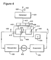
- An exemplary system for power generation in which some components of a conventional Rankine system have been removed for simplicity and brevity
- the components described for a Rankine cycle and shown in Figure 1 can be used in a similar power generation unit which uses the exemplary turboexpander and control system described below.
- the system is pressurized and the working fluid circulated (in the direction shown by the arrowheads) in the closed-loop Rankine cycle system by the pump 402.
- the working fluid e.g., an ORC fluid
- This pressurized vapor then goes to the turboexpander 406 which has a first expansion stage 408 and a second expansion stage 410.
- multiple expanders may be used instead of a single expander having multiple stages. The novel features discussed herein apply to both multiple expanders or a single expander with multiple stages.
- the first expansion stage 408 includes an inlet guide vane 412 which regulates an amount/rate of pressurized vapor entering the first expansion stage 408.
- the pressurized vapor expends some energy during expansion and travels on to the second expansion stage 410, entering the second expansion stage 410 through another inlet guide vane 414 which also regulates an amount/rate of vapor entering the second expansion stage 410.
- the expanded vapor leaves the second expansion stage 410 and exits the turboexpander 406 enroute to a recuperator 428 which allows for heat exchange of the working fluid.
- the working fluid then goes through other steps of the Rankine cycle (not shown) enroute to the pump 402 to repeat the cycle.
- Sensors 430 represent pressure monitoring sensors and sensor 432 represents one or more sensor(s) used to monitor power output efficiency (e.g., current and/or voltage sensors).
- Controller 434 controls settings of the power generation system.
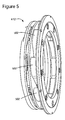
- FIG. 5 An example of an inlet guide vane 412 is shown in Figure 5 .
- Variable geometry inlet guide vanes 502 can be set to various positions or angles, which can be changed to control the flow of the working fluid into the expansion stage. Additionally, according to exemplary embodiments, by controlling the position of the vanes 502, the pressure P1 (shown in Figure 4 ) can be regulated to be within an upper maximum range.
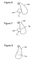
- Figures 6-8 show different positions of a single vane 502 in relation to a corresponding fluid inlet 602.
- a 1 represents the open area of the fluid inlet 602 and
- a 01 represents the area of the fluid inlet 602 which is blocked by the variable geometry inlet guide vane 502.
- Figure 6 shows a fully open fluid inlet 602
- Figure 7 shows a partially open fluid inlet 602
- Figure 8 shows a fully blocked fluid inlet 602. While only three positions are shown in Figures 6-8 , other angular positions of the vanes 502 are possible. Additionally, the various positions of the vanes 502 with respect to the fluid inlet 602 creates a variable geometry inlet nozzle for fluid entering the expansion sections of the turboexpander 406.
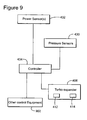
- controller 434 can control settings, parameters, software and other controls associated with the power generation system.
- Various control elements and exemplary communication links are shown in Figure 9 , including controller 434.
- Other controls may include power sensor(s) 432 which can be used to gather current, voltage and/or other power-related information from an associated power generation unit, e.g., a generator.
- Pressure sensors 430 can be used to gather pressure data from various locations in the power generation cycle.
- Control equipment 902 as shown in Figure 9 can also be used in the power generation system. These control elements can all be in communication with the controller 434, however other communication links can also exist, e.g., a backup communication link or other direct links between the control elements can be present. Controller 434 is also in communication with the turboexpander 406 and the controls for the inlet guide vane 412 and 414. This allows the controller 434 to issue instructions for changing the angle of the inlet guide vanes 412 and 414. While controller 434 is shown as a single unit, multiple controllers 434 can exist in the system with duties being spread out among the units as desired. Additionally, the exemplary embodiments described herein could be performed by a controller 434 which is integrated with another piece of equipment, e.g., the controls of the turboexpander 406.
- systems and methods can in a two-stage (or more) turboexpander have the first expansion stage regulate the upper pressure of a Rankine cycle within a pressure range such that a second expansion stage can regulate itself to automatically find the optimal expansion ratio associated with a maximum power output from, for example, the generator in the associated power generation system.
- this exemplary process can be performed when the power generation system is operating with partial loads to improve the power output.
- an efficiency of the expander is directly proportional to a power output of the generator driven by the turboexpander. This process can be performed as shown in the flowchart of Figure 10 .
- the power generation system is operating and there is an initial value of the pressure P1of the working fluid in step 1002 as it enters the inlet guide vane 412 of the first expansion stage of the turboexpander.
- the inlet guide vane 412 regulates the flow of gas to obtain and maintain a desired set value of P1, e.g., 50 bar, within a desirable range, e.g., a range of +/-1 or +/- 0.5 bar, in step 1004.
- the inlet guide vane 412 is regulated, for example, by controller 434 to adjust the angle of the vanes to obtain the desired pressure P1 which may be determined or set for example, by plant optimal performance parameters. While the inlet guide vane 412 regulates the flow of gas for the first stage, the inlet guide vane 414 regulates the flow of gas for the second stage as shown in step 1006. The inlet guide vane 414 regulates the flow of gas in a manner described later so as to not disrupt system pressure while the inlet guide vane 412 is regulating the flow of gas. This prevents the inlet guide vane 412 from always changing the angle of the vanes to obtain and maintain the desired P1 value in the predetermined window.
- Expansion Efficiency Electrical Power Generation / Enthalpy Flow Rate with the Enthalpy Flow Rate becoming a constant when the inlet guide vane 412 is fixed and the turboexpander is chocked. It is noted that when the turboexpander is chocked, a constant mass flows through the device. For simplicity of calculations, both stages of the turboexpander are considered to be chocked. As the enthalpy flow rate is constant under chocked conditions, the expansion efficiency of the turboexpander is proportional to the electrical power generation of the associated generator.
- the inlet guide vane 414 is controlled to sweep through various vane angles so that a power output of the power generation is varied.
- This power output is measured and in one application stored in a database.
- the controller 434 checks for the point of maximum power output by both sweeping up and sweeping down from the initial angular start point of the vanes in the inlet guide vane 414 and captures data for each vane position. According to an exemplary embodiment, this sweeping can occur in about 20 seconds, however other time frames can be used as desired.
- the power output of the power generator 424 is determined as shown in step 1010.
- the process is repeated, otherwise the process ends with the inlet guide vane 414 vane angle becoming fixed.
- the controller 434 determines from the database which angle of the inlet guide vane 414 maximizes the power output of the power generator 424 and sets the angle of the inlet guide vane 414 accordingly. This sweeping process can be repeated and rechecked over time as desired. Additionally, if P1 falls out of the desired range due to system changes, e.g., the load changes which can affect temperature and pressure of the working fluid, the entire process shown in the flowchart of Figure 10 can be repeated.
- the inlet guide vane 414 is configured to abandon the angle that maximizes the efficiency of the turboexpander 406 and to follow the inlet guide vane 412 until the P1 is brought in the desired range.
- various algorithms can be used to describe the relationship between the inlet guide vane 412 and the inlet guide vane 414 for different stages of regulating their respective gas flows. Assumptions used in the algorithms described below include using a mach number of one and that the system is operating in a chocked condition.
- a 2 A 1 ⁇ f P 1 ⁇ P 2 ⁇ T 1 ⁇ T 2 , where A 1 is the area of a fluid inlet not blocked by a vane at the inlet guide vane 412 (see Figure 7 ), A 2 is the area of a fluid inlet not blocked by a vane at the inlet guide vane 414 (not shown but similar to A 1 in Figure 7 ), P 1 is the pressure of the working fluid at the first inlet guide vane stage 412, P 2 is the pressure of the working fluid at the inlet guide vane 414, T 1 is the temperature of the working fluid at the inlet guide vane 412, and T 2 is the temperature of the working fluid at the inlet guide vane 414.
- a 1 A t ⁇ 1 A 2 A t ⁇ 2 , where A t1 is the total area (see A 1 + A 01 in Figure 7 ) of a fluid inlet through a vane at the inlet guide vane 412 and A t2 is the total area (not shown but similar to A t1 in Figure 7 ) of a fluid inlet through a vane at the inlet guide vane 414.
- the relationship between the inlet guide vane 412 and the inlet guide vane 414 is set up so that the inlet guide vane 414 practically does not influence the pressure of the flow of gas entering the inlet guide vane 412.
- the angle of the inlet guide vane 412 is fixed and only the angle of the inlet guide vane 414 is adjusted until the efficiency of the turboexpander 406 is maximized.
- the inlet guide vane 414 becomes independent of the inlet guide vane 12 and the area A 2 of the unblocked fluid inlet for the inlet guide vane 414 is described by equation (5):
- a 2 m k ⁇ k + 1 2 1 2 ⁇ k + 1 k - 1 ⁇ ⁇ 2 ⁇ R ⁇ T 2 , wherein k is the isentropic coefficient of the gas, m is the working fluid mass flow rate and R is the gas constant.
- the inlet guide vane 414 can sweep up and down through various angles to determine the maximum power output point of the power generator 424 which, as described above, is associated with maximizing expansion efficiency of the turboexpander 406.
- This sweeping, as controlled by the controller 434 (or one of its associated control elements) is kept within a range so as to not allow P1 to leave the predetermined range. However, if P1 leaves the predetermined (desired) range, the sweeping process for the inlet guide vane 414 is suspended and the inlet guide vane 412 starts to regulate the flow of gas to bring P1 to the predetermined range.
- the various values of the angles and the measured variables indicative of the expander efficiency for the inlet guide vane 414 may be stored in a memory. After the sweeping process is completed, the controller 434 may compare the stored values and select that value that maximize the expansion efficiency of the turboexpander 406 and set the value of the inlet guide vane 414 to have the selected value.
- turboexpander 406 can have more than two expansion stages with at least one expansion stage regulating system pressure and another expansion stage maximizing power efficiency.
- exemplary embodiments by using the inlet guide vane 412 of the first expansion stage 408 to regulate pressure, there is no need for a dedicated valve to be in-line with the working fluid to control system pressure as the working fluid enters the first expansion stage 408. Additionally, exemplary embodiments can be used in situations where the operating conditions of the power generation system change, e.g., partial loads and varying ambient temperatures.
- one working fluid that can be used in a Rankine cycle is an ORC fluid.
- ORC fluids include, but are not limited to, pentane, propane, cyclohexane, cyclopentane, butane, a fluorohydrocarbon such as R-245fa, and a ketone such as acetone or an aromatic such as toluene or thiophene.
- R-245fa fluorohydrocarbon
- ketone such as acetone or an aromatic such as toluene or thiophene.
- an intermediate thermo-oil loop or another fluid can be used in power generation systems which use the exemplary turboexpander 406.
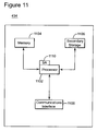
- Controller 434 can contain a processor 1102 (or multiple processor cores), memory 1104, one or more secondary storage devices 1106, a communications interface 1108 and a software application 1110.
- Processor 1102 can execute instructions for performing exemplary embodiments as described herein. Additionally, the processor 1102 can include instructions for execution in support of operating and controlling a power generation system.
- Memory 1104 can store these instructions as well as sensor information and the results obtained from the sweeping of the vanes. Additionally, information associated with P1 and the pressure range and the like can also be stored within the controller 434.
- the software application 1110 can represent programs associated with exemplary embodiment described herein as well as programs associated with the power generation system.
- the communications interface 1108 can communicate with sensors, other controllers and the like to operate the power generation system and transmit instructions associated with changing inlet guide vane angles. Accordingly, the exemplary embodiments described above can be controlled by controller 434.
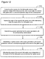
- a method for power generation includes a turboexpander with at least two expansion stages as shown in the flowchart of Figure 12 .
- the method includes a step 1200 of controlling (i) an angle of a first inlet guide vane in a first expansion stage of the turboexpander for maintaining an inlet pressure of the first expansion stage in a predetermined range, and (ii) an angle of a second inlet guide vane in a second expansion stage of the turboexpander for maintaining the inlet pressure at the first expansion stage in the predetermined range; a step 1202 of varying the angle of the second inlet guide vane while maintaining fixed the angle of the first inlet guide vane; a step 1204 of determining a power generated by the power generation unit for corresponding varying angles; a step 1206 of determining a highest power of the power generated by the power generation unit and a corresponding angle of the second inlet guide vane; and a step 1208 of adjusting the angle of the second inlet guide vane independent of the angle of the first
Landscapes
- Engineering & Computer Science (AREA)
- Chemical & Material Sciences (AREA)
- Combustion & Propulsion (AREA)
- Mechanical Engineering (AREA)
- General Engineering & Computer Science (AREA)
- Physics & Mathematics (AREA)
- Fluid Mechanics (AREA)
- Control Of Turbines (AREA)
- Supercharger (AREA)
- Control Of Positive-Displacement Air Blowers (AREA)
- Nozzles (AREA)
Applications Claiming Priority (1)
| Application Number | Priority Date | Filing Date | Title |
|---|---|---|---|
| ITCO2010A000029A IT1400053B1 (it) | 2010-05-24 | 2010-05-24 | Metodi e sistemi per ugelli di ingresso a geometria variabile per uso in turboespansori. |
Publications (2)
| Publication Number | Publication Date |
|---|---|
| EP2390470A1 EP2390470A1 (en) | 2011-11-30 |
| EP2390470B1 true EP2390470B1 (en) | 2013-03-27 |
Family
ID=43427052
Family Applications (1)
| Application Number | Title | Priority Date | Filing Date |
|---|---|---|---|
| EP11166438A Active EP2390470B1 (en) | 2010-05-24 | 2011-05-17 | Method and system for variable geometry inlets nozzles for use in turboexpanders |
Country Status (9)
| Country | Link |
|---|---|
| US (1) | US8882438B2 (ko) |
| EP (1) | EP2390470B1 (ko) |
| JP (1) | JP5981692B2 (ko) |
| KR (1) | KR20110128747A (ko) |
| CN (1) | CN102330574B (ko) |
| CA (1) | CA2740397C (ko) |
| IT (1) | IT1400053B1 (ko) |
| MX (1) | MX2011005405A (ko) |
| RU (1) | RU2565679C2 (ko) |
Cited By (2)
| Publication number | Priority date | Publication date | Assignee | Title |
|---|---|---|---|---|
| US10975733B2 (en) | 2015-04-24 | 2021-04-13 | Nuovo Pignone Srl | Compressor driven by ORC waste heat recovery unit and control method |
| EP3384203B1 (en) * | 2015-12-02 | 2022-06-15 | Nuovo Pignone Tecnologie S.r.l. | Control system and method for pressure-let-downs stations |
Families Citing this family (10)
| Publication number | Priority date | Publication date | Assignee | Title |
|---|---|---|---|---|
| IT1400053B1 (it) * | 2010-05-24 | 2013-05-17 | Nuovo Pignone Spa | Metodi e sistemi per ugelli di ingresso a geometria variabile per uso in turboespansori. |
| AU2012373722B2 (en) * | 2012-03-15 | 2016-03-17 | Cyclect Electrical Engineering | Organic Rankine Cycle system |
| ITFI20120196A1 (it) * | 2012-10-01 | 2014-04-02 | Nuovo Pignone Srl | "a turboexpander and driven turbomachine system" |
| KR101375595B1 (ko) * | 2012-12-10 | 2014-03-19 | 주식회사 그린에너지시스템즈 | 저압 터빈 발전기 |
| US9777641B2 (en) * | 2012-12-19 | 2017-10-03 | General Electric Company | System for turbomachine vane control |
| US20140186170A1 (en) * | 2012-12-27 | 2014-07-03 | Ronald E. Graf | Centrifugal Expanders And Compressors Each Using Rotors In Both Flow Going From Periphery To Center And Flow Going From Center To Periphery Their Use In Engines Both External Heat And Internal Combustion. Means to convert radial inward flow to radial outward flow with less eddy currents |
| WO2014175765A1 (en) * | 2013-04-25 | 2014-10-30 | Siemens Aktiengesellschaft | Set of channel nozzles for a centripetal turboexpander |
| CN107407149A (zh) * | 2015-02-13 | 2017-11-28 | 埃克塞基股份公司 | 径向离心式涡轮机 |
| WO2018090307A1 (en) * | 2016-11-18 | 2018-05-24 | Air Liquide (China) Holding Co., Ltd. | A low friction inlet nozzle for a turbo expander |
| US10502126B2 (en) * | 2017-03-10 | 2019-12-10 | Garrett Transportation I Inc. | Adjustable-trim centrifugal compressor for a turbocharger |
Family Cites Families (32)
| Publication number | Priority date | Publication date | Assignee | Title |
|---|---|---|---|---|
| CH486636A (de) * | 1968-08-20 | 1970-02-28 | Escher Wyss Ag | Diffusor einer Zentrifugalfördermaschine |
| US4028884A (en) * | 1974-12-27 | 1977-06-14 | Westinghouse Electric Corporation | Control apparatus for controlling the operation of a gas turbine inlet guide vane assembly and heat recovery steam generator for a steam turbine employed in a combined cycle electric power generating plant |
| JPS55154307U (ko) * | 1979-04-23 | 1980-11-07 | ||
| JPS58200011A (ja) * | 1982-05-15 | 1983-11-21 | Kobe Steel Ltd | 冷熱発電設備における輻流タ−ビン制御方法 |
| ZA835029B (en) * | 1982-09-27 | 1984-03-28 | English Electric Co Ltd | Power-generation plant and method |
| GB2133839B (en) * | 1982-09-27 | 1985-09-25 | English Electric Co Ltd | Power plant comprising a pressurised fluidised bed combustor |
| JPS62139905A (ja) * | 1985-12-16 | 1987-06-23 | Hitachi Ltd | タ−ビン制御装置 |
| FR2595117B1 (fr) * | 1986-02-28 | 1991-05-17 | Mtu Muenchen Gmbh | Turbocompresseur a geometrie variable |
| JPH0454204A (ja) * | 1990-06-21 | 1992-02-21 | Mitsubishi Heavy Ind Ltd | 抽気復水タービンの制御装置 |
| US5301499A (en) * | 1990-06-28 | 1994-04-12 | General Electric Company | Overspeed anticipation and control system for single shaft combined cycle gas and steam turbine unit |
| RU2110022C1 (ru) * | 1996-04-29 | 1998-04-27 | Леонид Иванович Архипов | Система регулирования турбодетандера |
| US5841104A (en) | 1996-09-03 | 1998-11-24 | Abb Flexible Automation, Inc. | Method and system for multiple pass welding |
| US5993152A (en) * | 1997-10-14 | 1999-11-30 | General Electric Company | Nonlinear vane actuation |
| US5851104A (en) * | 1997-12-15 | 1998-12-22 | Atlas Copco Rotoflow, Inc. | Nozzle adjusting mechanism |
| GB9911867D0 (en) * | 1999-05-22 | 1999-07-21 | Rolls Royce Plc | A combustion chamber assembly and a method of operating a combustion chamber assembly |
| US6422014B1 (en) * | 2001-09-06 | 2002-07-23 | Caterpillar Inc. | Turbocharger with controllable flow geometry for two stage turbine |
| RU2206755C1 (ru) * | 2001-11-12 | 2003-06-20 | Закрытое акционерное общество НПО "Турбодетандеры" | Высокоскоростная турбомашина |
| DE60313392T2 (de) * | 2002-05-16 | 2007-08-09 | Rolls-Royce Plc | Gasturbine |
| JP4069675B2 (ja) * | 2002-05-22 | 2008-04-02 | 株式会社日立プラントテクノロジー | ターボ圧縮機およびその容量制御方法 |
| US7146813B2 (en) * | 2002-11-13 | 2006-12-12 | Utc Power, Llc | Power generation with a centrifugal compressor |
| US7290393B2 (en) * | 2004-05-06 | 2007-11-06 | Utc Power Corporation | Method for synchronizing an induction generator of an ORC plant to a grid |
| US7428816B2 (en) * | 2004-07-16 | 2008-09-30 | Honeywell International Inc. | Working fluids for thermal energy conversion of waste heat from fuel cells using Rankine cycle systems |
| FR2885968B1 (fr) * | 2005-05-17 | 2007-08-10 | Snecma Moteurs Sa | Systeme de commande d'etages d'aubes de stator a angle de calage variable de turbomachine |
| FR2885969B1 (fr) * | 2005-05-17 | 2007-08-10 | Snecma Moteurs Sa | Systeme de commande d'etages d'aubes de stator a angle de calage variable de turbomachine |
| JP4699130B2 (ja) * | 2005-08-03 | 2011-06-08 | 三菱重工業株式会社 | ガスタービンの入口案内翼制御装置 |
| WO2007088194A2 (de) | 2006-02-02 | 2007-08-09 | Frank Eckert | Organic rankine zyklus (orc) - turbogenerator |
| US7315778B1 (en) * | 2006-08-30 | 2008-01-01 | General Electric Company | System and method for detecting and responding to fugitive fueling of an internal combustion engine |
| US9043118B2 (en) * | 2007-04-02 | 2015-05-26 | General Electric Company | Methods and systems for model-based control of gas turbines |
| ES2571212T3 (es) * | 2009-07-21 | 2016-05-24 | Alstom Technology Ltd | Método para el control de motores de turbina de gas |
| US20110142602A1 (en) * | 2009-12-15 | 2011-06-16 | Mohammad Waseem Adhami | Methods of determining variable element settings for a turbine engine |
| IT1400053B1 (it) * | 2010-05-24 | 2013-05-17 | Nuovo Pignone Spa | Metodi e sistemi per ugelli di ingresso a geometria variabile per uso in turboespansori. |
| US20130031902A1 (en) * | 2011-08-03 | 2013-02-07 | Rodrigo Rodriguez Erdmenger | Systems and methods for an engine with a two-stage turbocharger |
-
2010
- 2010-05-24 IT ITCO2010A000029A patent/IT1400053B1/it active
-
2011
- 2011-05-12 CA CA2740397A patent/CA2740397C/en active Active
- 2011-05-17 EP EP11166438A patent/EP2390470B1/en active Active
- 2011-05-20 MX MX2011005405A patent/MX2011005405A/es active IP Right Grant
- 2011-05-20 JP JP2011112944A patent/JP5981692B2/ja active Active
- 2011-05-23 KR KR1020110048518A patent/KR20110128747A/ko not_active Application Discontinuation
- 2011-05-23 US US13/113,616 patent/US8882438B2/en active Active
- 2011-05-23 RU RU2011120259/06A patent/RU2565679C2/ru active
- 2011-05-24 CN CN201110149693.7A patent/CN102330574B/zh active Active
Cited By (2)
| Publication number | Priority date | Publication date | Assignee | Title |
|---|---|---|---|---|
| US10975733B2 (en) | 2015-04-24 | 2021-04-13 | Nuovo Pignone Srl | Compressor driven by ORC waste heat recovery unit and control method |
| EP3384203B1 (en) * | 2015-12-02 | 2022-06-15 | Nuovo Pignone Tecnologie S.r.l. | Control system and method for pressure-let-downs stations |
Also Published As
| Publication number | Publication date |
|---|---|
| JP5981692B2 (ja) | 2016-08-31 |
| MX2011005405A (es) | 2012-04-24 |
| EP2390470A1 (en) | 2011-11-30 |
| CN102330574B (zh) | 2015-01-14 |
| US8882438B2 (en) | 2014-11-11 |
| IT1400053B1 (it) | 2013-05-17 |
| CA2740397A1 (en) | 2011-11-24 |
| KR20110128747A (ko) | 2011-11-30 |
| ITCO20100029A1 (it) | 2011-11-25 |
| RU2011120259A (ru) | 2012-11-27 |
| JP2011247257A (ja) | 2011-12-08 |
| CA2740397C (en) | 2018-02-13 |
| CN102330574A (zh) | 2012-01-25 |
| US20110305556A1 (en) | 2011-12-15 |
| RU2565679C2 (ru) | 2015-10-20 |
Similar Documents
| Publication | Publication Date | Title |
|---|---|---|
| EP2390470B1 (en) | Method and system for variable geometry inlets nozzles for use in turboexpanders | |
| US20110203278A1 (en) | Auto optimizing control system for organic rankine cycle plants | |
| US20130227947A1 (en) | Apparatus and method for increasing power plant efficiency at partial loads | |
| EP2930319B1 (en) | Rankine cycle device operation method | |
| JP6734363B2 (ja) | ガスタービンプラント、及びその運転方法 | |
| US10352246B2 (en) | Water feeding method, water feeding system implementing said method, and steam generating facility provided with water feeding system | |
| EP2937526B1 (en) | Combined heat and power system | |
| EP3306043B1 (en) | Combined cycle plant, device for controlling said plant and method for starting up said plant | |
| EP2508719B1 (en) | Method for starting a turbomachine | |
| JP6682619B2 (ja) | プラント、及びその運転方法 | |
| US9404395B2 (en) | Selective pressure kettle boiler for rotor air cooling applications | |
| RU2657061C1 (ru) | Турбина и способ расширения рабочей текучей среды | |
| US9145794B2 (en) | Apparatus and method for increasing power plant efficiency at partial loads | |
| JP2004245184A (ja) | 再熱蒸気タービンプラントとその起動方法 | |
| JP2002106305A (ja) | コンバインドサイクル発電プラントの起動制御装置 | |
| Pattanayak et al. | Design and part load performance simulation of natural gas combined cycle with new operating regulation for gas turbine | |
| JP6101604B2 (ja) | 蒸気タービンプラント、これを備えているコンバインドサイクルプラント、及び蒸気タービンプラントの運転方法 | |
| US20240175394A1 (en) | Combined power generation system and operation control method thereof | |
| EP4375489A1 (en) | Combined power generation system and operation control method thereof |
Legal Events
| Date | Code | Title | Description |
|---|---|---|---|
| AK | Designated contracting states |
Kind code of ref document: A1 Designated state(s): AL AT BE BG CH CY CZ DE DK EE ES FI FR GB GR HR HU IE IS IT LI LT LU LV MC MK MT NL NO PL PT RO RS SE SI SK SM TR |
|
| AX | Request for extension of the european patent |
Extension state: BA ME |
|
| PUAI | Public reference made under article 153(3) epc to a published international application that has entered the european phase |
Free format text: ORIGINAL CODE: 0009012 |
|
| 17P | Request for examination filed |
Effective date: 20120530 |
|
| REG | Reference to a national code |
Ref country code: DE Ref legal event code: R079 Ref document number: 602011001145 Country of ref document: DE Free format text: PREVIOUS MAIN CLASS: F01D0017160000 Ipc: F01K0007040000 |
|
| RIC1 | Information provided on ipc code assigned before grant |
Ipc: F01K 23/10 20060101ALI20120814BHEP Ipc: F01D 17/16 20060101ALI20120814BHEP Ipc: F02C 9/20 20060101ALI20120814BHEP Ipc: F02C 9/24 20060101ALI20120814BHEP Ipc: F04D 29/46 20060101ALI20120814BHEP Ipc: F01K 25/10 20060101ALI20120814BHEP Ipc: F02C 6/18 20060101ALI20120814BHEP Ipc: F01K 7/04 20060101AFI20120814BHEP |
|
| GRAP | Despatch of communication of intention to grant a patent |
Free format text: ORIGINAL CODE: EPIDOSNIGR1 |
|
| GRAS | Grant fee paid |
Free format text: ORIGINAL CODE: EPIDOSNIGR3 |
|
| GRAA | (expected) grant |
Free format text: ORIGINAL CODE: 0009210 |
|
| AK | Designated contracting states |
Kind code of ref document: B1 Designated state(s): AL AT BE BG CH CY CZ DE DK EE ES FI FR GB GR HR HU IE IS IT LI LT LU LV MC MK MT NL NO PL PT RO RS SE SI SK SM TR |
|
| REG | Reference to a national code |
Ref country code: GB Ref legal event code: FG4D |
|
| REG | Reference to a national code |
Ref country code: CH Ref legal event code: EP |
|
| REG | Reference to a national code |
Ref country code: AT Ref legal event code: REF Ref document number: 603543 Country of ref document: AT Kind code of ref document: T Effective date: 20130415 |
|
| REG | Reference to a national code |
Ref country code: IE Ref legal event code: FG4D |
|
| REG | Reference to a national code |
Ref country code: CH Ref legal event code: NV Representative=s name: SERVOPATENT GMBH, CH |
|
| REG | Reference to a national code |
Ref country code: DE Ref legal event code: R096 Ref document number: 602011001145 Country of ref document: DE Effective date: 20130529 |
|
| PG25 | Lapsed in a contracting state [announced via postgrant information from national office to epo] |
Ref country code: BG Free format text: LAPSE BECAUSE OF FAILURE TO SUBMIT A TRANSLATION OF THE DESCRIPTION OR TO PAY THE FEE WITHIN THE PRESCRIBED TIME-LIMIT Effective date: 20130627 Ref country code: SE Free format text: LAPSE BECAUSE OF FAILURE TO SUBMIT A TRANSLATION OF THE DESCRIPTION OR TO PAY THE FEE WITHIN THE PRESCRIBED TIME-LIMIT Effective date: 20130327 Ref country code: LT Free format text: LAPSE BECAUSE OF FAILURE TO SUBMIT A TRANSLATION OF THE DESCRIPTION OR TO PAY THE FEE WITHIN THE PRESCRIBED TIME-LIMIT Effective date: 20130327 |
|
| REG | Reference to a national code |
Ref country code: NL Ref legal event code: T3 |
|
| REG | Reference to a national code |
Ref country code: AT Ref legal event code: MK05 Ref document number: 603543 Country of ref document: AT Kind code of ref document: T Effective date: 20130327 |
|
| REG | Reference to a national code |
Ref country code: NO Ref legal event code: T2 Effective date: 20130327 |
|
| REG | Reference to a national code |
Ref country code: LT Ref legal event code: MG4D |
|
| PG25 | Lapsed in a contracting state [announced via postgrant information from national office to epo] |
Ref country code: LV Free format text: LAPSE BECAUSE OF FAILURE TO SUBMIT A TRANSLATION OF THE DESCRIPTION OR TO PAY THE FEE WITHIN THE PRESCRIBED TIME-LIMIT Effective date: 20130327 Ref country code: GR Free format text: LAPSE BECAUSE OF FAILURE TO SUBMIT A TRANSLATION OF THE DESCRIPTION OR TO PAY THE FEE WITHIN THE PRESCRIBED TIME-LIMIT Effective date: 20130628 Ref country code: FI Free format text: LAPSE BECAUSE OF FAILURE TO SUBMIT A TRANSLATION OF THE DESCRIPTION OR TO PAY THE FEE WITHIN THE PRESCRIBED TIME-LIMIT Effective date: 20130327 Ref country code: SI Free format text: LAPSE BECAUSE OF FAILURE TO SUBMIT A TRANSLATION OF THE DESCRIPTION OR TO PAY THE FEE WITHIN THE PRESCRIBED TIME-LIMIT Effective date: 20130327 |
|
| PG25 | Lapsed in a contracting state [announced via postgrant information from national office to epo] |
Ref country code: HR Free format text: LAPSE BECAUSE OF FAILURE TO SUBMIT A TRANSLATION OF THE DESCRIPTION OR TO PAY THE FEE WITHIN THE PRESCRIBED TIME-LIMIT Effective date: 20130327 Ref country code: BE Free format text: LAPSE BECAUSE OF FAILURE TO SUBMIT A TRANSLATION OF THE DESCRIPTION OR TO PAY THE FEE WITHIN THE PRESCRIBED TIME-LIMIT Effective date: 20130327 |
|
| PG25 | Lapsed in a contracting state [announced via postgrant information from national office to epo] |
Ref country code: RO Free format text: LAPSE BECAUSE OF FAILURE TO SUBMIT A TRANSLATION OF THE DESCRIPTION OR TO PAY THE FEE WITHIN THE PRESCRIBED TIME-LIMIT Effective date: 20130327 Ref country code: AT Free format text: LAPSE BECAUSE OF FAILURE TO SUBMIT A TRANSLATION OF THE DESCRIPTION OR TO PAY THE FEE WITHIN THE PRESCRIBED TIME-LIMIT Effective date: 20130327 Ref country code: EE Free format text: LAPSE BECAUSE OF FAILURE TO SUBMIT A TRANSLATION OF THE DESCRIPTION OR TO PAY THE FEE WITHIN THE PRESCRIBED TIME-LIMIT Effective date: 20130327 Ref country code: IS Free format text: LAPSE BECAUSE OF FAILURE TO SUBMIT A TRANSLATION OF THE DESCRIPTION OR TO PAY THE FEE WITHIN THE PRESCRIBED TIME-LIMIT Effective date: 20130727 Ref country code: CZ Free format text: LAPSE BECAUSE OF FAILURE TO SUBMIT A TRANSLATION OF THE DESCRIPTION OR TO PAY THE FEE WITHIN THE PRESCRIBED TIME-LIMIT Effective date: 20130327 Ref country code: PT Free format text: LAPSE BECAUSE OF FAILURE TO SUBMIT A TRANSLATION OF THE DESCRIPTION OR TO PAY THE FEE WITHIN THE PRESCRIBED TIME-LIMIT Effective date: 20130729 Ref country code: SK Free format text: LAPSE BECAUSE OF FAILURE TO SUBMIT A TRANSLATION OF THE DESCRIPTION OR TO PAY THE FEE WITHIN THE PRESCRIBED TIME-LIMIT Effective date: 20130327 Ref country code: ES Free format text: LAPSE BECAUSE OF FAILURE TO SUBMIT A TRANSLATION OF THE DESCRIPTION OR TO PAY THE FEE WITHIN THE PRESCRIBED TIME-LIMIT Effective date: 20130708 |
|
| PG25 | Lapsed in a contracting state [announced via postgrant information from national office to epo] |
Ref country code: CY Free format text: LAPSE BECAUSE OF FAILURE TO SUBMIT A TRANSLATION OF THE DESCRIPTION OR TO PAY THE FEE WITHIN THE PRESCRIBED TIME-LIMIT Effective date: 20130327 Ref country code: PL Free format text: LAPSE BECAUSE OF FAILURE TO SUBMIT A TRANSLATION OF THE DESCRIPTION OR TO PAY THE FEE WITHIN THE PRESCRIBED TIME-LIMIT Effective date: 20130327 |
|
| PG25 | Lapsed in a contracting state [announced via postgrant information from national office to epo] |
Ref country code: MC Free format text: LAPSE BECAUSE OF FAILURE TO SUBMIT A TRANSLATION OF THE DESCRIPTION OR TO PAY THE FEE WITHIN THE PRESCRIBED TIME-LIMIT Effective date: 20130327 |
|
| PG25 | Lapsed in a contracting state [announced via postgrant information from national office to epo] |
Ref country code: DK Free format text: LAPSE BECAUSE OF FAILURE TO SUBMIT A TRANSLATION OF THE DESCRIPTION OR TO PAY THE FEE WITHIN THE PRESCRIBED TIME-LIMIT Effective date: 20130327 |
|
| PLBE | No opposition filed within time limit |
Free format text: ORIGINAL CODE: 0009261 |
|
| STAA | Information on the status of an ep patent application or granted ep patent |
Free format text: STATUS: NO OPPOSITION FILED WITHIN TIME LIMIT |
|
| REG | Reference to a national code |
Ref country code: IE Ref legal event code: MM4A |
|
| 26N | No opposition filed |
Effective date: 20140103 |
|
| REG | Reference to a national code |
Ref country code: DE Ref legal event code: R097 Ref document number: 602011001145 Country of ref document: DE Effective date: 20140103 |
|
| PG25 | Lapsed in a contracting state [announced via postgrant information from national office to epo] |
Ref country code: IE Free format text: LAPSE BECAUSE OF NON-PAYMENT OF DUE FEES Effective date: 20130517 |
|
| PG25 | Lapsed in a contracting state [announced via postgrant information from national office to epo] |
Ref country code: MT Free format text: LAPSE BECAUSE OF FAILURE TO SUBMIT A TRANSLATION OF THE DESCRIPTION OR TO PAY THE FEE WITHIN THE PRESCRIBED TIME-LIMIT Effective date: 20130327 |
|
| PG25 | Lapsed in a contracting state [announced via postgrant information from national office to epo] |
Ref country code: SM Free format text: LAPSE BECAUSE OF FAILURE TO SUBMIT A TRANSLATION OF THE DESCRIPTION OR TO PAY THE FEE WITHIN THE PRESCRIBED TIME-LIMIT Effective date: 20130327 |
|
| PG25 | Lapsed in a contracting state [announced via postgrant information from national office to epo] |
Ref country code: TR Free format text: LAPSE BECAUSE OF FAILURE TO SUBMIT A TRANSLATION OF THE DESCRIPTION OR TO PAY THE FEE WITHIN THE PRESCRIBED TIME-LIMIT Effective date: 20130327 |
|
| PG25 | Lapsed in a contracting state [announced via postgrant information from national office to epo] |
Ref country code: RS Free format text: LAPSE BECAUSE OF FAILURE TO SUBMIT A TRANSLATION OF THE DESCRIPTION OR TO PAY THE FEE WITHIN THE PRESCRIBED TIME-LIMIT Effective date: 20130627 Ref country code: MK Free format text: LAPSE BECAUSE OF FAILURE TO SUBMIT A TRANSLATION OF THE DESCRIPTION OR TO PAY THE FEE WITHIN THE PRESCRIBED TIME-LIMIT Effective date: 20130327 Ref country code: HU Free format text: LAPSE BECAUSE OF FAILURE TO SUBMIT A TRANSLATION OF THE DESCRIPTION OR TO PAY THE FEE WITHIN THE PRESCRIBED TIME-LIMIT; INVALID AB INITIO Effective date: 20110517 Ref country code: LU Free format text: LAPSE BECAUSE OF NON-PAYMENT OF DUE FEES Effective date: 20130517 |
|
| PGFP | Annual fee paid to national office [announced via postgrant information from national office to epo] |
Ref country code: NO Payment date: 20150528 Year of fee payment: 5 Ref country code: CH Payment date: 20150527 Year of fee payment: 5 |
|
| PGFP | Annual fee paid to national office [announced via postgrant information from national office to epo] |
Ref country code: NL Payment date: 20150526 Year of fee payment: 5 |
|
| REG | Reference to a national code |
Ref country code: FR Ref legal event code: PLFP Year of fee payment: 6 |
|
| PGFP | Annual fee paid to national office [announced via postgrant information from national office to epo] |
Ref country code: GB Payment date: 20160527 Year of fee payment: 6 |
|
| REG | Reference to a national code |
Ref country code: NO Ref legal event code: MMEP |
|
| REG | Reference to a national code |
Ref country code: CH Ref legal event code: PL |
|
| REG | Reference to a national code |
Ref country code: NL Ref legal event code: MM Effective date: 20160601 |
|
| PG25 | Lapsed in a contracting state [announced via postgrant information from national office to epo] |
Ref country code: NO Free format text: LAPSE BECAUSE OF NON-PAYMENT OF DUE FEES Effective date: 20160531 Ref country code: CH Free format text: LAPSE BECAUSE OF NON-PAYMENT OF DUE FEES Effective date: 20160531 Ref country code: LI Free format text: LAPSE BECAUSE OF NON-PAYMENT OF DUE FEES Effective date: 20160531 |
|
| PG25 | Lapsed in a contracting state [announced via postgrant information from national office to epo] |
Ref country code: NL Free format text: LAPSE BECAUSE OF NON-PAYMENT OF DUE FEES Effective date: 20160601 |
|
| REG | Reference to a national code |
Ref country code: FR Ref legal event code: PLFP Year of fee payment: 7 |
|
| GBPC | Gb: european patent ceased through non-payment of renewal fee |
Effective date: 20170517 |
|
| PG25 | Lapsed in a contracting state [announced via postgrant information from national office to epo] |
Ref country code: GB Free format text: LAPSE BECAUSE OF NON-PAYMENT OF DUE FEES Effective date: 20170517 |
|
| REG | Reference to a national code |
Ref country code: FR Ref legal event code: PLFP Year of fee payment: 8 |
|
| PG25 | Lapsed in a contracting state [announced via postgrant information from national office to epo] |
Ref country code: AL Free format text: LAPSE BECAUSE OF FAILURE TO SUBMIT A TRANSLATION OF THE DESCRIPTION OR TO PAY THE FEE WITHIN THE PRESCRIBED TIME-LIMIT Effective date: 20130327 |
|
| PGFP | Annual fee paid to national office [announced via postgrant information from national office to epo] |
Ref country code: IT Payment date: 20230420 Year of fee payment: 13 Ref country code: FR Payment date: 20230420 Year of fee payment: 13 Ref country code: DE Payment date: 20230419 Year of fee payment: 13 |