EP3384203B1 - Control system and method for pressure-let-downs stations - Google Patents
Control system and method for pressure-let-downs stations Download PDFInfo
- Publication number
- EP3384203B1 EP3384203B1 EP16815564.6A EP16815564A EP3384203B1 EP 3384203 B1 EP3384203 B1 EP 3384203B1 EP 16815564 A EP16815564 A EP 16815564A EP 3384203 B1 EP3384203 B1 EP 3384203B1
- Authority
- EP
- European Patent Office
- Prior art keywords
- gas
- heat
- heat transfer
- temperature
- transfer fluid
- Prior art date
- Legal status (The legal status is an assumption and is not a legal conclusion. Google has not performed a legal analysis and makes no representation as to the accuracy of the status listed.)
- Active
Links
- 238000000034 method Methods 0.000 title claims description 24
- 239000013529 heat transfer fluid Substances 0.000 claims description 68
- 238000012546 transfer Methods 0.000 claims description 34
- 239000012530 fluid Substances 0.000 claims description 31
- 238000010438 heat treatment Methods 0.000 claims description 10
- 230000008859 change Effects 0.000 claims description 8
- 238000011144 upstream manufacturing Methods 0.000 claims description 7
- 230000001419 dependent effect Effects 0.000 claims description 2
- 239000007789 gas Substances 0.000 description 202
- CURLTUGMZLYLDI-UHFFFAOYSA-N Carbon dioxide Chemical compound O=C=O CURLTUGMZLYLDI-UHFFFAOYSA-N 0.000 description 8
- 230000008569 process Effects 0.000 description 7
- 238000010586 diagram Methods 0.000 description 5
- 230000009466 transformation Effects 0.000 description 5
- 229910002092 carbon dioxide Inorganic materials 0.000 description 4
- 230000006837 decompression Effects 0.000 description 4
- 238000013461 design Methods 0.000 description 4
- XLYOFNOQVPJJNP-UHFFFAOYSA-N water Substances O XLYOFNOQVPJJNP-UHFFFAOYSA-N 0.000 description 4
- 230000007423 decrease Effects 0.000 description 3
- 230000000694 effects Effects 0.000 description 3
- 230000033228 biological regulation Effects 0.000 description 2
- 239000001569 carbon dioxide Substances 0.000 description 2
- 230000005494 condensation Effects 0.000 description 2
- 238000009833 condensation Methods 0.000 description 2
- 238000010276 construction Methods 0.000 description 2
- 125000004122 cyclic group Chemical group 0.000 description 2
- 230000007613 environmental effect Effects 0.000 description 2
- 229930195733 hydrocarbon Natural products 0.000 description 2
- 150000002430 hydrocarbons Chemical class 0.000 description 2
- VNWKTOKETHGBQD-UHFFFAOYSA-N methane Chemical compound C VNWKTOKETHGBQD-UHFFFAOYSA-N 0.000 description 2
- 238000000844 transformation Methods 0.000 description 2
- 239000003570 air Substances 0.000 description 1
- 239000012080 ambient air Substances 0.000 description 1
- 230000015572 biosynthetic process Effects 0.000 description 1
- 238000009529 body temperature measurement Methods 0.000 description 1
- 238000004364 calculation method Methods 0.000 description 1
- 239000003638 chemical reducing agent Substances 0.000 description 1
- 230000006835 compression Effects 0.000 description 1
- 238000007906 compression Methods 0.000 description 1
- 238000001816 cooling Methods 0.000 description 1
- 150000004677 hydrates Chemical class 0.000 description 1
- 238000009434 installation Methods 0.000 description 1
- 239000007788 liquid Substances 0.000 description 1
- 239000000203 mixture Substances 0.000 description 1
- 238000012986 modification Methods 0.000 description 1
- 230000004048 modification Effects 0.000 description 1
- 239000003345 natural gas Substances 0.000 description 1
- 238000011084 recovery Methods 0.000 description 1
- 230000009467 reduction Effects 0.000 description 1
Images


Classifications
-
- F—MECHANICAL ENGINEERING; LIGHTING; HEATING; WEAPONS; BLASTING
- F17—STORING OR DISTRIBUTING GASES OR LIQUIDS
- F17D—PIPE-LINE SYSTEMS; PIPE-LINES
- F17D1/00—Pipe-line systems
- F17D1/02—Pipe-line systems for gases or vapours
- F17D1/04—Pipe-line systems for gases or vapours for distribution of gas
- F17D1/05—Preventing freezing
-
- F—MECHANICAL ENGINEERING; LIGHTING; HEATING; WEAPONS; BLASTING
- F17—STORING OR DISTRIBUTING GASES OR LIQUIDS
- F17D—PIPE-LINE SYSTEMS; PIPE-LINES
- F17D1/00—Pipe-line systems
- F17D1/02—Pipe-line systems for gases or vapours
- F17D1/065—Arrangements for producing propulsion of gases or vapours
- F17D1/075—Arrangements for producing propulsion of gases or vapours by mere expansion from an initial pressure level, e.g. by arrangement of a flow-control valve
-
- F—MECHANICAL ENGINEERING; LIGHTING; HEATING; WEAPONS; BLASTING
- F25—REFRIGERATION OR COOLING; COMBINED HEATING AND REFRIGERATION SYSTEMS; HEAT PUMP SYSTEMS; MANUFACTURE OR STORAGE OF ICE; LIQUEFACTION SOLIDIFICATION OF GASES
- F25B—REFRIGERATION MACHINES, PLANTS OR SYSTEMS; COMBINED HEATING AND REFRIGERATION SYSTEMS; HEAT PUMP SYSTEMS
- F25B11/00—Compression machines, plants or systems, using turbines, e.g. gas turbines
- F25B11/02—Compression machines, plants or systems, using turbines, e.g. gas turbines as expanders
-
- F—MECHANICAL ENGINEERING; LIGHTING; HEATING; WEAPONS; BLASTING
- F25—REFRIGERATION OR COOLING; COMBINED HEATING AND REFRIGERATION SYSTEMS; HEAT PUMP SYSTEMS; MANUFACTURE OR STORAGE OF ICE; LIQUEFACTION SOLIDIFICATION OF GASES
- F25B—REFRIGERATION MACHINES, PLANTS OR SYSTEMS; COMBINED HEATING AND REFRIGERATION SYSTEMS; HEAT PUMP SYSTEMS
- F25B49/00—Arrangement or mounting of control or safety devices
-
- F—MECHANICAL ENGINEERING; LIGHTING; HEATING; WEAPONS; BLASTING
- F16—ENGINEERING ELEMENTS AND UNITS; GENERAL MEASURES FOR PRODUCING AND MAINTAINING EFFECTIVE FUNCTIONING OF MACHINES OR INSTALLATIONS; THERMAL INSULATION IN GENERAL
- F16L—PIPES; JOINTS OR FITTINGS FOR PIPES; SUPPORTS FOR PIPES, CABLES OR PROTECTIVE TUBING; MEANS FOR THERMAL INSULATION IN GENERAL
- F16L53/00—Heating of pipes or pipe systems; Cooling of pipes or pipe systems
- F16L53/30—Heating of pipes or pipe systems
-
- F—MECHANICAL ENGINEERING; LIGHTING; HEATING; WEAPONS; BLASTING
- F17—STORING OR DISTRIBUTING GASES OR LIQUIDS
- F17C—VESSELS FOR CONTAINING OR STORING COMPRESSED, LIQUEFIED OR SOLIDIFIED GASES; FIXED-CAPACITY GAS-HOLDERS; FILLING VESSELS WITH, OR DISCHARGING FROM VESSELS, COMPRESSED, LIQUEFIED, OR SOLIDIFIED GASES
- F17C13/00—Details of vessels or of the filling or discharging of vessels
- F17C13/10—Arrangements for preventing freezing
-
- F—MECHANICAL ENGINEERING; LIGHTING; HEATING; WEAPONS; BLASTING
- F17—STORING OR DISTRIBUTING GASES OR LIQUIDS
- F17C—VESSELS FOR CONTAINING OR STORING COMPRESSED, LIQUEFIED OR SOLIDIFIED GASES; FIXED-CAPACITY GAS-HOLDERS; FILLING VESSELS WITH, OR DISCHARGING FROM VESSELS, COMPRESSED, LIQUEFIED, OR SOLIDIFIED GASES
- F17C2221/00—Handled fluid, in particular type of fluid
- F17C2221/03—Mixtures
- F17C2221/032—Hydrocarbons
- F17C2221/033—Methane, e.g. natural gas, CNG, LNG, GNL, GNC, PLNG
-
- F—MECHANICAL ENGINEERING; LIGHTING; HEATING; WEAPONS; BLASTING
- F17—STORING OR DISTRIBUTING GASES OR LIQUIDS
- F17C—VESSELS FOR CONTAINING OR STORING COMPRESSED, LIQUEFIED OR SOLIDIFIED GASES; FIXED-CAPACITY GAS-HOLDERS; FILLING VESSELS WITH, OR DISCHARGING FROM VESSELS, COMPRESSED, LIQUEFIED, OR SOLIDIFIED GASES
- F17C2223/00—Handled fluid before transfer, i.e. state of fluid when stored in the vessel or before transfer from the vessel
- F17C2223/01—Handled fluid before transfer, i.e. state of fluid when stored in the vessel or before transfer from the vessel characterised by the phase
- F17C2223/0107—Single phase
- F17C2223/0123—Single phase gaseous, e.g. CNG, GNC
-
- F—MECHANICAL ENGINEERING; LIGHTING; HEATING; WEAPONS; BLASTING
- F17—STORING OR DISTRIBUTING GASES OR LIQUIDS
- F17C—VESSELS FOR CONTAINING OR STORING COMPRESSED, LIQUEFIED OR SOLIDIFIED GASES; FIXED-CAPACITY GAS-HOLDERS; FILLING VESSELS WITH, OR DISCHARGING FROM VESSELS, COMPRESSED, LIQUEFIED, OR SOLIDIFIED GASES
- F17C2223/00—Handled fluid before transfer, i.e. state of fluid when stored in the vessel or before transfer from the vessel
- F17C2223/03—Handled fluid before transfer, i.e. state of fluid when stored in the vessel or before transfer from the vessel characterised by the pressure level
- F17C2223/035—High pressure (>10 bar)
-
- F—MECHANICAL ENGINEERING; LIGHTING; HEATING; WEAPONS; BLASTING
- F17—STORING OR DISTRIBUTING GASES OR LIQUIDS
- F17C—VESSELS FOR CONTAINING OR STORING COMPRESSED, LIQUEFIED OR SOLIDIFIED GASES; FIXED-CAPACITY GAS-HOLDERS; FILLING VESSELS WITH, OR DISCHARGING FROM VESSELS, COMPRESSED, LIQUEFIED, OR SOLIDIFIED GASES
- F17C2225/00—Handled fluid after transfer, i.e. state of fluid after transfer from the vessel
- F17C2225/01—Handled fluid after transfer, i.e. state of fluid after transfer from the vessel characterised by the phase
- F17C2225/0107—Single phase
- F17C2225/0123—Single phase gaseous, e.g. CNG, GNC
-
- F—MECHANICAL ENGINEERING; LIGHTING; HEATING; WEAPONS; BLASTING
- F17—STORING OR DISTRIBUTING GASES OR LIQUIDS
- F17C—VESSELS FOR CONTAINING OR STORING COMPRESSED, LIQUEFIED OR SOLIDIFIED GASES; FIXED-CAPACITY GAS-HOLDERS; FILLING VESSELS WITH, OR DISCHARGING FROM VESSELS, COMPRESSED, LIQUEFIED, OR SOLIDIFIED GASES
- F17C2225/00—Handled fluid after transfer, i.e. state of fluid after transfer from the vessel
- F17C2225/03—Handled fluid after transfer, i.e. state of fluid after transfer from the vessel characterised by the pressure level
- F17C2225/033—Small pressure, e.g. for liquefied gas
-
- F—MECHANICAL ENGINEERING; LIGHTING; HEATING; WEAPONS; BLASTING
- F17—STORING OR DISTRIBUTING GASES OR LIQUIDS
- F17C—VESSELS FOR CONTAINING OR STORING COMPRESSED, LIQUEFIED OR SOLIDIFIED GASES; FIXED-CAPACITY GAS-HOLDERS; FILLING VESSELS WITH, OR DISCHARGING FROM VESSELS, COMPRESSED, LIQUEFIED, OR SOLIDIFIED GASES
- F17C2225/00—Handled fluid after transfer, i.e. state of fluid after transfer from the vessel
- F17C2225/03—Handled fluid after transfer, i.e. state of fluid after transfer from the vessel characterised by the pressure level
- F17C2225/035—High pressure, i.e. between 10 and 80 bars
-
- F—MECHANICAL ENGINEERING; LIGHTING; HEATING; WEAPONS; BLASTING
- F17—STORING OR DISTRIBUTING GASES OR LIQUIDS
- F17C—VESSELS FOR CONTAINING OR STORING COMPRESSED, LIQUEFIED OR SOLIDIFIED GASES; FIXED-CAPACITY GAS-HOLDERS; FILLING VESSELS WITH, OR DISCHARGING FROM VESSELS, COMPRESSED, LIQUEFIED, OR SOLIDIFIED GASES
- F17C2227/00—Transfer of fluids, i.e. method or means for transferring the fluid; Heat exchange with the fluid
- F17C2227/03—Heat exchange with the fluid
- F17C2227/0302—Heat exchange with the fluid by heating
- F17C2227/0309—Heat exchange with the fluid by heating using another fluid
- F17C2227/0316—Water heating
-
- F—MECHANICAL ENGINEERING; LIGHTING; HEATING; WEAPONS; BLASTING
- F17—STORING OR DISTRIBUTING GASES OR LIQUIDS
- F17C—VESSELS FOR CONTAINING OR STORING COMPRESSED, LIQUEFIED OR SOLIDIFIED GASES; FIXED-CAPACITY GAS-HOLDERS; FILLING VESSELS WITH, OR DISCHARGING FROM VESSELS, COMPRESSED, LIQUEFIED, OR SOLIDIFIED GASES
- F17C2227/00—Transfer of fluids, i.e. method or means for transferring the fluid; Heat exchange with the fluid
- F17C2227/03—Heat exchange with the fluid
- F17C2227/0302—Heat exchange with the fluid by heating
- F17C2227/0309—Heat exchange with the fluid by heating using another fluid
- F17C2227/0323—Heat exchange with the fluid by heating using another fluid in a closed loop
-
- F—MECHANICAL ENGINEERING; LIGHTING; HEATING; WEAPONS; BLASTING
- F17—STORING OR DISTRIBUTING GASES OR LIQUIDS
- F17C—VESSELS FOR CONTAINING OR STORING COMPRESSED, LIQUEFIED OR SOLIDIFIED GASES; FIXED-CAPACITY GAS-HOLDERS; FILLING VESSELS WITH, OR DISCHARGING FROM VESSELS, COMPRESSED, LIQUEFIED, OR SOLIDIFIED GASES
- F17C2227/00—Transfer of fluids, i.e. method or means for transferring the fluid; Heat exchange with the fluid
- F17C2227/03—Heat exchange with the fluid
- F17C2227/0367—Localisation of heat exchange
- F17C2227/0388—Localisation of heat exchange separate
- F17C2227/039—Localisation of heat exchange separate on the pipes
-
- F—MECHANICAL ENGINEERING; LIGHTING; HEATING; WEAPONS; BLASTING
- F17—STORING OR DISTRIBUTING GASES OR LIQUIDS
- F17C—VESSELS FOR CONTAINING OR STORING COMPRESSED, LIQUEFIED OR SOLIDIFIED GASES; FIXED-CAPACITY GAS-HOLDERS; FILLING VESSELS WITH, OR DISCHARGING FROM VESSELS, COMPRESSED, LIQUEFIED, OR SOLIDIFIED GASES
- F17C2250/00—Accessories; Control means; Indicating, measuring or monitoring of parameters
- F17C2250/04—Indicating or measuring of parameters as input values
- F17C2250/0404—Parameters indicated or measured
- F17C2250/043—Pressure
-
- F—MECHANICAL ENGINEERING; LIGHTING; HEATING; WEAPONS; BLASTING
- F17—STORING OR DISTRIBUTING GASES OR LIQUIDS
- F17C—VESSELS FOR CONTAINING OR STORING COMPRESSED, LIQUEFIED OR SOLIDIFIED GASES; FIXED-CAPACITY GAS-HOLDERS; FILLING VESSELS WITH, OR DISCHARGING FROM VESSELS, COMPRESSED, LIQUEFIED, OR SOLIDIFIED GASES
- F17C2250/00—Accessories; Control means; Indicating, measuring or monitoring of parameters
- F17C2250/04—Indicating or measuring of parameters as input values
- F17C2250/0404—Parameters indicated or measured
- F17C2250/0439—Temperature
-
- F—MECHANICAL ENGINEERING; LIGHTING; HEATING; WEAPONS; BLASTING
- F17—STORING OR DISTRIBUTING GASES OR LIQUIDS
- F17C—VESSELS FOR CONTAINING OR STORING COMPRESSED, LIQUEFIED OR SOLIDIFIED GASES; FIXED-CAPACITY GAS-HOLDERS; FILLING VESSELS WITH, OR DISCHARGING FROM VESSELS, COMPRESSED, LIQUEFIED, OR SOLIDIFIED GASES
- F17C2250/00—Accessories; Control means; Indicating, measuring or monitoring of parameters
- F17C2250/06—Controlling or regulating of parameters as output values
- F17C2250/0605—Parameters
- F17C2250/0626—Pressure
-
- F—MECHANICAL ENGINEERING; LIGHTING; HEATING; WEAPONS; BLASTING
- F17—STORING OR DISTRIBUTING GASES OR LIQUIDS
- F17C—VESSELS FOR CONTAINING OR STORING COMPRESSED, LIQUEFIED OR SOLIDIFIED GASES; FIXED-CAPACITY GAS-HOLDERS; FILLING VESSELS WITH, OR DISCHARGING FROM VESSELS, COMPRESSED, LIQUEFIED, OR SOLIDIFIED GASES
- F17C2250/00—Accessories; Control means; Indicating, measuring or monitoring of parameters
- F17C2250/06—Controlling or regulating of parameters as output values
- F17C2250/0605—Parameters
- F17C2250/0631—Temperature
-
- F—MECHANICAL ENGINEERING; LIGHTING; HEATING; WEAPONS; BLASTING
- F17—STORING OR DISTRIBUTING GASES OR LIQUIDS
- F17C—VESSELS FOR CONTAINING OR STORING COMPRESSED, LIQUEFIED OR SOLIDIFIED GASES; FIXED-CAPACITY GAS-HOLDERS; FILLING VESSELS WITH, OR DISCHARGING FROM VESSELS, COMPRESSED, LIQUEFIED, OR SOLIDIFIED GASES
- F17C2250/00—Accessories; Control means; Indicating, measuring or monitoring of parameters
- F17C2250/06—Controlling or regulating of parameters as output values
- F17C2250/0605—Parameters
- F17C2250/0636—Flow or movement of content
-
- F—MECHANICAL ENGINEERING; LIGHTING; HEATING; WEAPONS; BLASTING
- F17—STORING OR DISTRIBUTING GASES OR LIQUIDS
- F17C—VESSELS FOR CONTAINING OR STORING COMPRESSED, LIQUEFIED OR SOLIDIFIED GASES; FIXED-CAPACITY GAS-HOLDERS; FILLING VESSELS WITH, OR DISCHARGING FROM VESSELS, COMPRESSED, LIQUEFIED, OR SOLIDIFIED GASES
- F17C2265/00—Effects achieved by gas storage or gas handling
- F17C2265/06—Fluid distribution
- F17C2265/068—Distribution pipeline networks
-
- F—MECHANICAL ENGINEERING; LIGHTING; HEATING; WEAPONS; BLASTING
- F17—STORING OR DISTRIBUTING GASES OR LIQUIDS
- F17C—VESSELS FOR CONTAINING OR STORING COMPRESSED, LIQUEFIED OR SOLIDIFIED GASES; FIXED-CAPACITY GAS-HOLDERS; FILLING VESSELS WITH, OR DISCHARGING FROM VESSELS, COMPRESSED, LIQUEFIED, OR SOLIDIFIED GASES
- F17C2265/00—Effects achieved by gas storage or gas handling
- F17C2265/07—Generating electrical power as side effect
Definitions
- the disclosure relates to gas transportation. More specifically, the disclosure relates to so-called pressure-let-down stations, where a pressurized gas is de-pressurized for distribution in a distribution grid, at a lower pressure.
- Embodiments disclosed herein relate to systems and methods for providing efficient depressurization of the gas and at least partial recovery of the pressure energy.
- EP 2 264 288 A1 discloses a system for depressurizing fluids.
- EP 1 865 249 A2 discloses a gas pressure reducer.
- Natural gas is one of the primary sources of energy used for both domestic as well as industrial uses. Natural gas, usually comprised of a mixture of hydrocarbons, is transported through transportation pipelines over long distances and then distributed in distribution networks or grids.
- Gas is transported in the transportation pipelines at relatively high pressure, for instance in the range of 55-65 bar.
- gas is present at a substantially lower pressure, e.g. in the range of 6-24 bar, depending upon local legislation.
- Pressure-let-down stations are used, wherein gas flows from the transportation pipeline towards the distribution network while the pressure of the gas is reduced as required.
- the gas In commonly used pressure-let-down stations the gas is caused to expand in pressure control valves, also called Joule Thomson (JT) valves. The entire energy associated to the pressure is dissipated in the pressure control valve. During decompression the gas cools down due to the Joule-Thomson effect. The heavier hydrocarbons present in the gas can condensate if too a low gas temperature is achieved at the end of the decompression process.
- a minimum admissible temperature at the inlet of the distribution network is usually set by legislation. The minimum temperature is usually around 0-5°C. Thus, before decompression, the gas is heated such that the final temperature thereof, after decompression, does not drop below the minimum admissible gas temperature at the inlet of the distribution network.
- Compressed gas is usually heated by heat exchange against hot water, which is in turn produced in a boiler, where a portion of the gas transported in the distribution network is burned to generate heat.
- Depressurizing gas from a first, transportation pressure to a second, distribution pressure, lower than the transportation pressure is thus an energy-consuming process due to two factors: on the one hand the pressure energy present in the gas is dissipated. On the other hand, a certain amount of gas must be consumed just for the purpose of heating the high-pressure gas to prevent the temperature of the low-pressure gas to drop below the minimum admissible gas temperature.
- gas is expanded in a turboexpander, e.g. a radial turbine, which converts at least part of the pressure energy contained in the gas flow into mechanical power.
- a turboexpander e.g. a radial turbine
- US-8,028,535 suggests using a transcritical heat pump as a source of heat for heating the gas in a gas depressurization system.
- the use of a transcritical heat pump can, under certain operating conditions, result in a more efficient depressurization system, in view of the high coefficient of performance which a transcritical heat pump can achieve when operating between the ambient temperature and the high temperature required to be achieved by the gas to be expanded in the depressurization system.
- depressurization systems using transcritical heat pumps may not be expedient under certain operating conditions, namely when the gas flow rate is reduced with respect to a design flow rate through the expander.
- the gas flow rate has dramatic daily fluctuations, e.g. since at nighttime a much smaller amount of gas is required. Strong yearly fluctuations are also to be taken into account, due to larger consumption of gas during the cold season, as well as due to variations of gas consumption linked to variations in the industrial activity, which also can vary during the year.
- a system for depressurizing a gas in a pipeline comprising an expander configured and arranged for generating mechanical power by expanding gas from a first, higher pressure to a second, lower pressure.
- the system further comprises a heat pump and a heat transfer circuit containing a heat transfer fluid circulating therein, for receiving heat from the heat pump and delivering the heat to the gas through a heat exchanger.
- the system also comprises a controller, configured and arranged for modulating a flow rate of the heat transfer fluid circulating in the heat transfer circuit as a function of a heat rate to be transferred from the heat transfer fluid to the gas, namely as a function of temperature differentials between the gas and the heat transfer fluid at a gas inlet side and a gas outlet side of the heat exchanger.
- the heat exchanger is arranged upstream of the expander with respect to a direction of flow of the gas in the pipeline. The gas is thus heated prior to expansion in the expander.
- the heat pump can be a transcritical heat pump, e.g. a transcritical heat pump using carbon dioxide as a working fluid.
- a transcritical heat pump is such a heat pump wherein the working fluid is in a supercritical state in at least a portion of the working circuit.
- the controller can be configured and arranged for modulating the flow rate of the heat transfer fluid as a function of temperature differentials between the gas and the heat transfer fluid at a gas inlet side and a gas outlet side of the heat exchanger, in order to set the flow rate of the heat transfer fluid such that the optimal coefficient of performance of the heat pump can be achieved.
- a method for depressurizing a gas in a pipeline comprising the following steps:
- transcritical heat pump indicates a heat pump, in which a working fluid undergoes cyclic thermodynamic transformations and changes between supercritical and subcritical states.
- FIG. 1 A schematic of an exemplary embodiment of the system according to the present disclosure is shown in Fig. 1 .
- the system is arranged between a high-pressure gas transportation pipeline 3 and a low-pressure gas distribution network 5.
- the system 1 comprises a pipeline 7, fluidly coupled to the high-pressure gas transportation pipeline 3.
- a heat exchanger 9 is arranged along the pipeline 7.
- the heat exchanger 9 can be a counter-flow heat exchanger.
- An expander 11 for instance a radial turboexpander, is arranged downstream of the heat exchanger 9, with respect to the direction of flow (arrow F) of the gas in the pipeline 7.
- the inlet of the expander 11 is fluidly coupled to the outlet of the heat exchanger 9, while the outlet of the expander 11 is fluidly coupled to the low-pressure gas distribution network 5.
- the expander 11 can be provided with variable inlet guide vanes (IGVs) schematically shown at 11A, which can be controlled to adjust the gas flow rate through the expander 11, as will be described in greater detail later on.
- the expander 11 is designed to support a maximum flow rate therethrough and the variable IGVs 11A are used to adjust the flow rate from a minimum to said maximum flow rate, depending upon the demand for gas from the low-pressure gas distribution network 5.
- the expander 11 is arranged and configured for expanding gas therein from a first, higher pressure upstream of the expander 11 to a second, lower pressure downstream of the expander 11. Work is generated through gas expansion and mechanical power is available on an expander shaft 13.
- the mechanical power can be converted in electric power.
- the expander shaft 13 can be mechanically coupled to an electric generator 15, which converts mechanical power generated by the expander 11 into electric power, which is delivered to an electric distribution grid 17 or directly to one or more electric loads (not shown).
- the gas flowing through the heat exchanger 9 is in heat-exchange relationship with a heat transfer circuit 19, where through a heat transfer fluid is circulated, for instance by a pump 21.
- the heat transfer fluid can be a liquid, for instance water, or any other suitable fluid.
- Arrow HT represents the direction of flow of the heat transfer fluid in the heat transfer circuit 19.
- the heat transfer fluid in the heat transfer circuit 19 transfers heat to the gas flowing through the pipeline 7 and the heat exchanger 9.
- the heat transfer fluid is moreover in heat exchange relationship with a high-temperature side of a heat pump 23, wherefrom the heat transfer fluid receives heat.
- the heat pump 23 is a transcritical heat pump.
- the transcritical heat pump 23 is comprised of a working fluid circuit schematically shown at 25, wherein a working fluid undergoes cyclic thermodynamic transformations to extract heat from a low-temperature heat source, for instance air, water or the ground, and release heat at a higher temperature to the heat transfer fluid circulating in the heat transfer circuit 19.
- Reference number 27 schematically indicates the low-temperature heat exchanger of the transcritical heat pump 23, in heat-exchange relationship with the low-temperature heat source.
- Reference number 29 schematically indicates the high-temperature heat exchanger of the transcritical heat pump 23.
- the heat transfer circuit 19 interposed between the transcritical heat pump 23 and the heat exchanger 9 allows the heat exchanger 9 and the pipeline 7 to be arranged separately and at a distance from the transcritical heat pump 23.
- High-pressure gas from the high-pressure gas transportation pipeline 3 enters the pipeline 7 at an inlet pressure Pin and at an inlet temperature T in .
- the inlet pressure Pin depends upon the conditions of operation of the high-pressure gas transportation pipeline 3, while the inlet temperature T in depends inter alia upon environmental factors, since the high-pressure gas transportation pipeline 3 can be located in the ground, the temperature whereof can fluctuate depending upon environmental conditions.
- a substantially constant gas outlet pressure must be maintained at the inlet of the low-pressure gas distribution network 5, i.e. downstream of the expander 11.
- the system 1 is controlled such that the gas outlet pressure P out is maintained around a pressure set point Ps.
- the gas temperature T out downstream of the expander 11 shall not drop below a minimum gas outlet temperature.
- the system 1 can be controlled such that the gas outlet temperature T out is maintained around a temperature set point Ts, or can be maintained above said temperature set point.
- Heat provided by the transcritical heat pump 23 increases the gas temperature prior to expansion in the expander 11, such that the gas outlet temperature T out can be maintained around the temperature set point Ts or above.
- the temperature set point Ts can be around 0°-5°C, for example, or any other temperature value consistent with regulations applied in the country, where the system 1 is installed. Even though a temperature higher than the minimum temperature allowed by regulations could be used, in preferred embodiments the temperature set point Ts is preferably set at the minimum allowable value, such that thermal power required to heat the gas prior to expansion is minimized.
- a temperature control loop can be provided to maintain the temperature T out around the temperature set point Ts.
- the temperature control loop could be omitted, and the temperature at the inlet of the expander 11 can be selected such that the temperature T out is always above a minimum temperature set point. This, however, would not be optimal from the point of view of energy saving. Indeed, if the expander operates at a reduced gas flow rate, i.e. at a flow rate below the design point, a reduced amount of electric power is generated, while an excess amount of thermal energy would be consumed for heating the gas prior to expansion, such that the ratio between electric power produced by expansion and electric power consumed for pre-heating the gas would drop below optimal.
- the expander 11 is designed such that the maximum gas flow therethrough is lower than the maximum expected gas flow demand from the low-pressure gas distribution network 5.
- An auxiliary gas delivery duct can be provided to supply gas in excess of the maximum gas flow allowed through the expander 11.
- the circuit comprising the pipeline 7, the heat exchanger 9 and the expander 11 is arranged in parallel to a gas delivery duct 37 having an inlet fluidly coupled to the high-pressure gas transportation pipeline 3 and an outlet fluidly coupled to the low-pressure gas distribution network 5.
- a pressure control valve arrangement 39 and a heater arrangement 41 can be provided along the gas delivery duct 37 .
- the heater arrangement 41 can be arranged downstream of the pressure control valve arrangement. In other, presently preferred embodiments, as shown in the drawing, the heater arrangement 41 is arranged upstream of the pressure control valve arrangement 39 with respect to the direction (arrow GD) of the gas flow through the gas delivery duct 37.
- the pressure control valve arrangement 39 can be closed, such that no gas will flow through the gas delivery duct 37 and the entire gas flow demand from the low-pressure gas distribution network 5 will be supplied through pipeline 7. This specifically happens when the low-pressure gas distribution network 5 requires a gas flow rate which is equal to, or lower than the maximum design flow rate of the expander 11. Conversely, if a higher gas flow rate is demanded by the low-pressure gas distribution network 5, gas will flow also through the gas delivery duct 37.
- the pressure control valve arrangement 39 can comprise one pressure control valve, or else a plurality of pressure control valves 39.1, 39.2, ... 39.n arranged in parallel, as schematically shown in Fig. 1 .
- Each pressure control valve 39.1, 39.2, .... 39.n can be selectively opened or closed, depending upon the gas flow rate demand.
- the heater arrangement 41 can be comprised of a heater 43, a secondary heat transfer circuit 45 and a heat exchanger 47. Heat generated in the heater 43, e.g. by burning gas supplied by the high-pressure gas transportation pipeline 3, is transferred through the secondary heat transfer circuit 45 to the gas flowing in the gas delivery duct 37, when one or more of the pressure control valves 39.1 - 39.n are open.
- the system 1 described so far operates as follows. If the demand from low-pressure gas distribution network 5 is lower than the maximum flowrate that can flow through the expander 11, gas will flow only through pipeline 7 and expander 11, while the pressure control valves 39.1-39.n are closed. The gas expands in the expander 11 from the inlet pressure P in (or a slightly lower pressure, if the losses along pipeline 7 and heat exchanger 9 are taken into account) to the outlet pressure P out , which shall be maintained around the pressure set point Ps. The pressure drop across expander 11 generates mechanical power, which is converted into electric power by the electric generator 15 and is available on the electric power distribution grid 17.
- the gas exiting the expander 11 has an outlet temperature T out , which must be maintained around the temperature set point Ts.
- heat Q provided by the transcritical heat pump 23 is transferred through the heat exchanger 9 to the gas flowing in pipeline 7.
- the heat Q exchanged in the heat exchanger 9 increases the gas temperature from a gas inlet temperature T1 at a gas inlet side of the heat exchanger 9, to a gas outlet temperature T2 at a gas outlet side of the heat exchanger 9.
- the heat exchanger 9 is a counter-flow heat exchanger. Therefore, the heat transfer fluid enters the heat exchanger 9 at the exit side of the gas at an inlet temperature T3 and exits the heat exchanger 9 at the gas inlet side at a temperature T4.
- Fig.3 illustrates a heat-vs-temperature diagram showing the temperature of the two fluids on the vertical axis, versus the heat flow on the horizontal axis.
- the line W represents the temperature of the heat transfer fluid, e.g. water
- the line G represents the temperature of the gas.
- the line CO2 in Fig.3 represents the temperature of the working fluid, e.g. carbon dioxide, in the transcritical heat pump 23.
- T5 and T6 are the inlet temperature and outlet temperature, respectively, of the working fluid in heat exchanger 29, where heat Q2 ( Fig.1 ) is exchanged by the working fluid of the transcritical heat pump 23 against the heat transfer fluid in the heat transfer circuit 19.
- Fig.2 illustrates the thermodynamic cycle of the working fluid in the working fluid circuit 25 of the transcritical heat pump 23.
- High-temperature heat is rejected from the working fluid along an isobaric curve AB, along which the temperature of the working fluid drops from temperature T5 to temperature T6. Heat is transferred to the heat transfer fluid circulating in heat transfer circuit 19.
- the working fluid in this phase is in a supercritical state.
- the working fluid is expanded in the expansion valve 31 (see curve BC in Fig.2 ), reaching a lower temperature and lower pressure.
- the expanded fluid is heated by heat exchange in the heat exchanger 27, evaporates and can achieve a superheated state (curve CDE in Fig.2 ).
- compressor 33 compresses the working fluid (see curve EF in Fig.2 ) until the required temperature T5 is achieved.
- the straight line W represents the temperature increase of the heat transfer fluid exchanging heat against the working fluid in the counter-flow heat exchanger 29.
- the temperature T2 is set such that after expansion the gas temperature T out at the inlet of the low-pressure gas distribution network 5 is around the temperature set point Ts, e.g. 5°C.
- the amount of heat Q that shall be provided by the transcritical heat pump 23 to the gas depends upon the gas flow rate and the initial temperature T1 of the pressurized gas, which in turn depends upon the gas inlet temperature T in .
- the transcritical heat pump 23 provides the required amount of heat which ensures that the temperature T out is maintained around the temperature set point Ts.
- T1, T2, T3, T4, T5, T6, T out and T in represent the temperatures of the fluids in the respective points of the fluid circuits, and also schematically indicate temperature transducers for measuring said temperatures, if needed.
- P in and P out indicate the respective pressure values and can indicate pressure transducers for detecting the pressure values.
- the Coefficient of Performance (COP) of the transcritical heat pump 23 is a function of the mean temperature between T5 and T6 and increases as said mean temperature decreases.
- COP Coefficient of Performance
- the transcritical heat pump 23 has an internal heat pump controller 23C, which sets the conditions in the working fluid circuit 25, such as to maximize the COP for a given temperature T5.
- Methods and algorithms have been developed by heat pump manufacturers for this purpose and are usually run by the heat pump controller 23C.
- a change in the gas demand from the low-pressure gas distribution network 5 causes in turn a change in the outlet pressure. More specifically, if the gas demand increases, the pressure P out tends to drop. Conversely, if less gas is demanded from the low-pressure gas distribution network 5, the pressure P out tends to increase.
- a controller 51 is provided, which features a pressure control loop.
- a pressure transducer (schematically shown at P out in Fig.1 ) can measure the actual value of the outlet pressure P out .
- the measured outlet pressure value P out is compared by the controller 51 with the pressure set point Ps.
- the pressure control loop calculates the error between the measured value P out and the pressure set point Ps and generates a pressure error signal Ep.
- the pressure error signal Ep can be used to act upon the variable IGVs 11A of the expander 11, for instance through a suitable actuator that opens or closes the variable IGVs 11A depending upon the error signal Ep.
- the pressure error signal Ep causes opening of the variable IGVs 11A to increase gas flow rate through the expander 11. Conversely, if the pressure P out tends to rise above the pressure set point Ps, the pressure error signal Ep causes the variable IGVs 11A to partly close, thus reducing the gas flow rate.
- the gas temperature T2 at the expander inlet and consequently the gas outlet temperature T out also change.
- the temperature T out is further influenced by the efficiency of the expander 11, which is in turn dependent upon the gas flow rate.
- a temperature control loop is featured by controller 51, for controlling the gas outlet temperature T out , to counteract fluctuations thereof caused by a variation of the gas flow rate through the expander 11, such that the gas outlet temperature T out is maintained around the temperature set point Ts.
- the controller 51 receives information on the actual temperature T out , e.g. by a suitable temperature transducer (represented in Fig. 1 by reference T out ) and generates a temperature error signal Et based on the measured T out and the gas temperature set point Ts.
- the temperature error signal Et is used as an input parameter for the controller 23C of the transcritical heat pump 23.
- the temperature error signal Et requests additional power from the transcritical heat pump 23.
- the controller 51 will thus generate a temperature error signal Et, which will inform the transcritical heat pump 23 that less duty (less heat power) is demanded.
- the transcritical heat pump 23 reacts to the temperature error signal Et by modifying the operating point of the transcritical heat pump 23.
- the control method applied by the controller 23C of the transcritical heat pump 23 can be any one of the methods used by heat pump manufacturers.
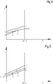
- Figs.4 and 5 show the same curves CO2, W and G, as already described in connection with Fig.3 , but in a partial load condition, i.e. when the amount of heat to be provided to the gas flowing in pipeline 7 is around 50% of the heat required in the operating condition shown in Fig. 3 (full load). This can be due for instance to a drop in the gas demand from the low-pressure gas distribution network 5 and a consequent reduction of the gas flow rate through the expander 11.
- the flow rate of the heat transfer fluid in the heat transfer circuit 19 is identical to the flow rate in Fig.3 .
- Fig.5 a situation is depicted, wherein the same amount of heat as in Fig. 4 is transferred by the transcritical heat pump 23 to the gas in pipeline 7 through the heat transfer circuit 19, but using a different flow rate of the heat transfer fluid circulating therein.
- the gas temperature at the inlet and outlet of the heat exchanger 9 are labeled T1' and T2', respectively.
- the inlet and outlet temperatures of the heat transfer fluid are labeled T3' and T4'.
- References T5' and T6' designate the temperatures of the working fluid of the transcritical heat pump 23 at the inlet and outlet of the heat exchanger 29, respectively.
- the operating condition of the transcritical heat pump 23 is controlled by the controller 23C such that the COP of the transcritical heat pump 23 is maximized under the conditions set by controller 51.
- the temperatures T5' and T6' and consequently the temperatures T3' and T4' are determined by the controller 23C, and are such that the gas temperature T2' ensures the gas outlet temperature T out remains around the temperature set point Ts.
- the angle of inclination of the line G is proportional to 1 mg ⁇ cpg wherein:
- Fig.4 shows that the heat exchanger 9 is in actual fact over-sized, as evidenced by the difference between temperature of the gas and the temperature of the heat transfer fluid becoming zero at a certain point; i.e. only a portion of the total heat exchanger surface is actually exploited.
- the same amount of heat (50% of Q) can be transferred from the heat transfer fluid to the gas flowing in pipeline 7 under a different operating condition of the heat transfer circuit 19, by changing the flow rate of the heat transfer fluid.
- Fig. 5 shows a situation where the same amount of heat as in Fig.4 is delivered to the gas flowing in pipeline 7, using a lower flow rate of the heat transfer fluid in the heat transfer circuit 19.
- the change in the flow rate of the heat transfer fluid corresponds to a variation of the inclination ⁇ of the curve W.
- the operating conditions of Figs. 4 and 5 both meet the request from the temperature control loop and pressure control loop featured by controller 51, and both correspond to an operating point of the transcritical heat pump 23 which maximizes the COP thereof.
- controller 51 controls the flow rate of the heat transfer fluid in the heat transfer circuit 19
- two different COP can be achieved, the one corresponding to a lower flow rate of the heat transfer fluid being higher, since the mean temperature of the working fluid in the working fluid circuit of the transcritical heat pump 23 along line AB is lower.
- the pressure control loop and the temperature control loop of controller 51 cause the operating point of system 1 to change in order to maintain the outlet temperature T out and the outlet pressure P out of the gas downstream of the expander 11 around the temperature set point Ts and the pressure set point Ps, respectively. More specifically, the pressure control loop modifies the gas flow rate through pipeline 7 and expander 11.
- the temperature control loop causes adjustment of the gas temperature T2 at the outlet of the heat exchanger 9. For a given flow rate of the heat transfer fluid in the heat transfer circuit 19, the gas temperature T2 can be achieved under a univocally determined operating condition of the transcritical heat pump 23, which provides the maximum COP, said univocally determined operating condition being set by the controller 23C of the transcritical heat pump 23.
- the flow rate of the heat transfer fluid in the heat transfer circuit 19 is a further variable of the system, which can be acted upon to further optimize the COP of the transcritical heat pump 23.
- a further control loop can thus be provided, which controls the flow rate of the heat transfer fluid in the heat transfer circuit 19, e.g. by changing the rotational speed of pump 21.
- This further control loop will be referred to herein as flowrate control loop.
- the flowrate control loop changes the flow rate of the heat transfer fluid in heat transfer circuit 19 to set the flow rate at an optimal value, which corresponds to an optimal maximum COP of the transcritical heat pump 23.
- the flowrate control circuit can provide a flowrate control signal Ef(see Fig.1 ), which is applied to pump 21, for changing the flow rate of the heat transfer fluid until optimal COP conditions are achieved.
- the above described flowrate control loop is particularly effective, since it is based on simple temperature measurements, which can be performed by temperature sensors, schematically shown in Fig. 1 at T1, T2, T3 and T4.
- the method does not require access to data from the transcritical heat pump 23 and does not require complex thermodynamic calculations. It also does not require any knowledge of information on the internal operation of the transcritical heat pump 23.
- the flowrate control loop can be configured also in a different manner.
- the COP of the transcritical heat pump 23 can be calculated for a given set of operating parameters.
- the flowrate control loop can for instance be based on an iterative perturb-and-observe algorithm and cause stepwise variations of the flow rate of the heat transfer fluid in the heat transfer circuit 19. If the flow rate variation causes a drop of the COP, this means that an opposite variation is required and will be applied at the next iterative step. For instance, if an increase of the flow rate of the heat transfer fluid causes a drop of the COP, the next iterative step will decrease the flow rate, until the maximum COP is achieved for a given working point of the expander 11.
- the expander 11 is dimensioned to support a gas flow rate which is only a fraction of the maximum flow rate, which can be delivered through the system 1. This takes into account the fact that a pressure-let-down system operates for most of the time under partial-load conditions. It would thus be ineffective to design the expander 11 and the transcritical heat pump 23 to support the maximum gas flow rate, which can be demanded by the low-pressure gas distribution network 5.
- One of the pressure control valves 39.1-39.n is partly opened and used for dynamically adapting the flow rate therethrough to meet the request from the low-pressure gas distribution network 5, maintaining the outlet gas pressure at the requested pressure set point Ps.
- the heater 41 is used to heat the gas flowing through the pressure control valve arrangement 39 such that the outlet gas temperature T out is maintained at the temperature set point Ts. Control of the pressure control valve arrangement 39 and of the heater 41 can be performed in a manner known per se by a controller separate from controller 51.
- the temperature T out is actually measured downstream of a point where the gas flowing through expander 11 mixes with the gas flowing through the pressure control valve arrangement 39, as shown in Fig.1 .
- What matters and shall be controlled is in fact the gas temperature at the outlet of the system 1, which depends upon the flow rates through the two gas flow paths 7 and 37.
- the gas can be heated downstream of the expander 11 rather than upstream thereof, by arranging the heat exchanger 9 downstream of the expander 11 with respect to the direction of the gas flow F. The same holds true for the heater arrangement 41 and the pressure control valve arrangement 39 along the delivery path 37.
Description
- The disclosure relates to gas transportation. More specifically, the disclosure relates to so-called pressure-let-down stations, where a pressurized gas is de-pressurized for distribution in a distribution grid, at a lower pressure. Embodiments disclosed herein relate to systems and methods for providing efficient depressurization of the gas and at least partial recovery of the pressure energy.
-
EP 2 264 288 A1 discloses a system for depressurizing fluids.EP 1 865 249 A2 discloses a gas pressure reducer. - Gas is one of the primary sources of energy used for both domestic as well as industrial uses. Natural gas, usually comprised of a mixture of hydrocarbons, is transported through transportation pipelines over long distances and then distributed in distribution networks or grids.
- Gas is transported in the transportation pipelines at relatively high pressure, for instance in the range of 55-65 bar. In a distribution network, where through gas is distributed to final users, gas is present at a substantially lower pressure, e.g. in the range of 6-24 bar, depending upon local legislation. Pressure-let-down stations are used, wherein gas flows from the transportation pipeline towards the distribution network while the pressure of the gas is reduced as required.
- In commonly used pressure-let-down stations the gas is caused to expand in pressure control valves, also called Joule Thomson (JT) valves. The entire energy associated to the pressure is dissipated in the pressure control valve. During decompression the gas cools down due to the Joule-Thomson effect. The heavier hydrocarbons present in the gas can condensate if too a low gas temperature is achieved at the end of the decompression process. In order to prevent condensation and/or formation of hydrates, a minimum admissible temperature at the inlet of the distribution network is usually set by legislation. The minimum temperature is usually around 0-5°C. Thus, before decompression, the gas is heated such that the final temperature thereof, after decompression, does not drop below the minimum admissible gas temperature at the inlet of the distribution network.
- Compressed gas is usually heated by heat exchange against hot water, which is in turn produced in a boiler, where a portion of the gas transported in the distribution network is burned to generate heat. Depressurizing gas from a first, transportation pressure to a second, distribution pressure, lower than the transportation pressure, is thus an energy-consuming process due to two factors: on the one hand the pressure energy present in the gas is dissipated. On the other hand, a certain amount of gas must be consumed just for the purpose of heating the high-pressure gas to prevent the temperature of the low-pressure gas to drop below the minimum admissible gas temperature.
- Attempts have been made to make the depressurization process less energy-consuming, by recovering the pressure energy from the gas. For this purpose, gas is expanded in a turboexpander, e.g. a radial turbine, which converts at least part of the pressure energy contained in the gas flow into mechanical power. The latter can then be exploited as such or converted into electric power by means of an electric generator.
- However, the pressure drop being the same, an expansion process through a turboexpander, which generates mechanical power, causes a much higher temperature drop than a JT valve. This is simply corresponds to the fact that the gas transformation is not an adiabatic transformation, but becomes a quasi-isentropic transformation, during which power is extracted from the flow of expanding gas.
- In order to meet the temperature requirements at the inlet of the gas distribution grid, therefore, more thermal power must be spent in order to heat the high-pressure gas at a temperature higher than that required if a simple JT valve is used for depressurizing purposes. Considering the revenue stream generated by the power generated by the expander versus the extra-amount of expenditure for heating, the resulting margin is so slim that it rarely justifies the higher investments required by complex machinery, as the turboexpander and electric generator.
-
US-8,028,535 suggests using a transcritical heat pump as a source of heat for heating the gas in a gas depressurization system. The use of a transcritical heat pump can, under certain operating conditions, result in a more efficient depressurization system, in view of the high coefficient of performance which a transcritical heat pump can achieve when operating between the ambient temperature and the high temperature required to be achieved by the gas to be expanded in the depressurization system. - However, it turned out that depressurization systems using transcritical heat pumps may not be expedient under certain operating conditions, namely when the gas flow rate is reduced with respect to a design flow rate through the expander. It shall be noted that, due to the kind of use made of this source of energy, the gas flow rate has dramatic daily fluctuations, e.g. since at nighttime a much smaller amount of gas is required. Strong yearly fluctuations are also to be taken into account, due to larger consumption of gas during the cold season, as well as due to variations of gas consumption linked to variations in the industrial activity, which also can vary during the year.
- Similar limitations and drawbacks are also encountered if a standard, i.e. non-transcritical, heat pump is used as a heating means for heating the pressurized gas prior to expansion in the expander.
- A need therefore exist, for further improving the efficiency of pressure-let-down stations using expanders and heat pumps as sources of heat to increase the gas temperature.
- According to a first aspect, disclosed herein is a system for depressurizing a gas in a pipeline, comprising an expander configured and arranged for generating mechanical power by expanding gas from a first, higher pressure to a second, lower pressure. The system further comprises a heat pump and a heat transfer circuit containing a heat transfer fluid circulating therein, for receiving heat from the heat pump and delivering the heat to the gas through a heat exchanger. The system also comprises a controller, configured and arranged for modulating a flow rate of the heat transfer fluid circulating in the heat transfer circuit as a function of a heat rate to be transferred from the heat transfer fluid to the gas, namely as a function of temperature differentials between the gas and the heat transfer fluid at a gas inlet side and a gas outlet side of the heat exchanger.
- In some embodiments, the heat exchanger is arranged upstream of the expander with respect to a direction of flow of the gas in the pipeline. The gas is thus heated prior to expansion in the expander.
- The heat pump can be a transcritical heat pump, e.g. a transcritical heat pump using carbon dioxide as a working fluid. A transcritical heat pump is such a heat pump wherein the working fluid is in a supercritical state in at least a portion of the working circuit.
- According to some embodiments, the controller can be configured and arranged for modulating the flow rate of the heat transfer fluid as a function of temperature differentials between the gas and the heat transfer fluid at a gas inlet side and a gas outlet side of the heat exchanger, in order to set the flow rate of the heat transfer fluid such that the optimal coefficient of performance of the heat pump can be achieved.
- According to a further aspect, disclosed herein is a method for depressurizing a gas in a pipeline, comprising the following steps:
- delivering a gas through a heat exchanger and an expander;
- expanding the gas from a first pressure to a second pressure in the expander and generating mechanical power therewith;
- heating the gas in the heat exchanger by delivering thereto heat from a heat pump through a heat transfer fluid circulating in a heat transfer circuit and in heat exchange relationship with the gas and with a working fluid processed by the heat pump;
- modulating a flow rate of the heat transfer fluid in the heat transfer circuit as a function of a heat rate to be transferred from the heat transfer fluid to the gas, namely as a function of temperature differentials between the gas and the heat transfer fluid at a gas inlet side and a gas outlet side of the heat exchanger.
- Features and embodiments are disclosed here below and are further set forth in the appended claims, which form an integral part of the present description. The above brief description sets forth features of the various embodiments of the present invention in order that the detailed description that follows may be better understood and in order that the present contributions to the art may be better appreciated. There are, of course, other features of the invention that will be described hereinafter and which will be set forth in the appended claims. In this respect, before explaining several embodiments of the invention in details, it is understood that the various embodiments of the invention are not limited in their application to the details of the construction and to the arrangements of the components set forth in the following description or illustrated in the drawings. The invention is capable of other embodiments and of being practiced and carried out in various ways. Also, it is to be understood that the phraseology and terminology employed herein are for the purpose of description and should not be regarded as limiting.
- As such, those skilled in the art will appreciate that the conception, upon which the disclosure is based, may readily be utilized as a basis for designing other structures, methods, and/or systems for carrying out the several purposes of the present invention. It is important, therefore, that the claims be regarded as including such equivalent constructions insofar as they do not depart from the spirit and scope of the present invention.
- A more complete appreciation of the disclosed embodiments of the invention and many of the attendant advantages thereof will be readily obtained as the same becomes better understood by reference to the following detailed description when considered in connection with the accompanying drawings, wherein:
-
Fig.1 illustrates a block diagram of an exemplary embodiment of a system according to the present disclosure; -
Fig.2 illustrates a thermodynamic cycle of a transcritical heat pump in a temperature-entropy diagram; -
Figs.3 ,4 and 5 illustrate heat transfer curves showing the heat transfer in the heat exchanger of the system ofFig. 1 in different operating conditions - The following detailed description of exemplary embodiments refers to the accompanying drawings. The same reference numbers in different drawings identify the same or similar elements. Additionally, the drawings are not necessarily drawn to scale. Also, the following detailed description does not limit the invention. Instead, the scope of the invention is defined by the appended claims.
- Reference throughout the specification to "one embodiment" or "an embodiment" or "some embodiments" means that the particular feature, structure or characteristic described in connection with an embodiment is included in at least one embodiment of the subject matter disclosed. Thus, the appearance of the phrase "in one embodiment" or "in an embodiment" or "in some embodiments" in various places throughout the specification is not necessarily referring to the same embodiment(s). Further, the particular features, structures or characteristics may be combined in any suitable manner in one or more embodiments.
- Herein after a detailed description of an exemplary embodiment of a system according to the present disclosure is provided, which uses a transcritical heat pump. It shall however be understood that at least some of the features of the system and method disclosed herein can be used also in installations using a standard, i.e. non-transcritical, heat pump.
- As used herein the term "transcritical heat pump" indicates a heat pump, in which a working fluid undergoes cyclic thermodynamic transformations and changes between supercritical and subcritical states.
- A schematic of an exemplary embodiment of the system according to the present disclosure is shown in
Fig. 1 . - The system, globally labeled 1, is arranged between a high-pressure gas transportation pipeline 3 and a low-pressure gas distribution network 5. The system 1 comprises a pipeline 7, fluidly coupled to the high-pressure gas transportation pipeline 3. A heat exchanger 9 is arranged along the pipeline 7. The heat exchanger 9 can be a counter-flow heat exchanger.
- An expander 11, for instance a radial turboexpander, is arranged downstream of the heat exchanger 9, with respect to the direction of flow (arrow F) of the gas in the pipeline 7. The inlet of the expander 11 is fluidly coupled to the outlet of the heat exchanger 9, while the outlet of the expander 11 is fluidly coupled to the low-pressure gas distribution network 5. The expander 11 can be provided with variable inlet guide vanes (IGVs) schematically shown at 11A, which can be controlled to adjust the gas flow rate through the expander 11, as will be described in greater detail later on. The expander 11 is designed to support a maximum flow rate therethrough and the variable IGVs 11A are used to adjust the flow rate from a minimum to said maximum flow rate, depending upon the demand for gas from the low-pressure gas distribution network 5.
- The expander 11 is arranged and configured for expanding gas therein from a first, higher pressure upstream of the expander 11 to a second, lower pressure downstream of the expander 11. Work is generated through gas expansion and mechanical power is available on an expander shaft 13. In some embodiments, the mechanical power can be converted in electric power. For instance, as shown in
Fig.1 , the expander shaft 13 can be mechanically coupled to an electric generator 15, which converts mechanical power generated by the expander 11 into electric power, which is delivered to an electric distribution grid 17 or directly to one or more electric loads (not shown). - The gas flowing through the heat exchanger 9 is in heat-exchange relationship with a heat transfer circuit 19, where through a heat transfer fluid is circulated, for instance by a pump 21. The heat transfer fluid can be a liquid, for instance water, or any other suitable fluid. Arrow HT represents the direction of flow of the heat transfer fluid in the heat transfer circuit 19. The heat transfer fluid in the heat transfer circuit 19 transfers heat to the gas flowing through the pipeline 7 and the heat exchanger 9. The heat transfer fluid is moreover in heat exchange relationship with a high-temperature side of a heat pump 23, wherefrom the heat transfer fluid receives heat. In the exemplary embodiment described herein the heat pump 23 is a transcritical heat pump.
- The transcritical heat pump 23 is comprised of a working fluid circuit schematically shown at 25, wherein a working fluid undergoes cyclic thermodynamic transformations to extract heat from a low-temperature heat source, for instance air, water or the ground, and release heat at a higher temperature to the heat transfer fluid circulating in the heat transfer circuit 19. Reference number 27 schematically indicates the low-temperature heat exchanger of the transcritical heat pump 23, in heat-exchange relationship with the low-temperature heat source. Reference number 29 schematically indicates the high-temperature heat exchanger of the transcritical heat pump 23. An expansion valve 31 and a compressor or pump 33, driven by an electric motor 35, divide the working fluid circuit 25 in a low pressure side and a high pressure side.
- The heat transfer circuit 19 interposed between the transcritical heat pump 23 and the heat exchanger 9 allows the heat exchanger 9 and the pipeline 7 to be arranged separately and at a distance from the transcritical heat pump 23.
- High-pressure gas from the high-pressure gas transportation pipeline 3 enters the pipeline 7 at an inlet pressure Pin and at an inlet temperature Tin. The inlet pressure Pin depends upon the conditions of operation of the high-pressure gas transportation pipeline 3, while the inlet temperature Tin depends inter alia upon environmental factors, since the high-pressure gas transportation pipeline 3 can be located in the ground, the temperature whereof can fluctuate depending upon environmental conditions.
- At the inlet of the low-pressure gas distribution network 5, i.e. downstream of the expander 11, a substantially constant gas outlet pressure must be maintained. The system 1 is controlled such that the gas outlet pressure Pout is maintained around a pressure set point Ps. In order to prevent condensation of gas components having a heavier molecular weight in the low-pressure gas distribution network 5, i.e. downstream of the expander 11, the gas temperature Tout downstream of the expander 11 shall not drop below a minimum gas outlet temperature. The system 1 can be controlled such that the gas outlet temperature Tout is maintained around a temperature set point Ts, or can be maintained above said temperature set point. Heat provided by the transcritical heat pump 23 increases the gas temperature prior to expansion in the expander 11, such that the gas outlet temperature Tout can be maintained around the temperature set point Ts or above.
- The temperature set point Ts can be around 0°-5°C, for example, or any other temperature value consistent with regulations applied in the country, where the system 1 is installed. Even though a temperature higher than the minimum temperature allowed by regulations could be used, in preferred embodiments the temperature set point Ts is preferably set at the minimum allowable value, such that thermal power required to heat the gas prior to expansion is minimized. A temperature control loop can be provided to maintain the temperature Tout around the temperature set point Ts.
- In other embodiments, the temperature control loop could be omitted, and the temperature at the inlet of the expander 11 can be selected such that the temperature Tout is always above a minimum temperature set point. This, however, would not be optimal from the point of view of energy saving. Indeed, if the expander operates at a reduced gas flow rate, i.e. at a flow rate below the design point, a reduced amount of electric power is generated, while an excess amount of thermal energy would be consumed for heating the gas prior to expansion, such that the ratio between electric power produced by expansion and electric power consumed for pre-heating the gas would drop below optimal.
- According to some embodiments, the expander 11 is designed such that the maximum gas flow therethrough is lower than the maximum expected gas flow demand from the low-pressure gas distribution network 5. An auxiliary gas delivery duct can be provided to supply gas in excess of the maximum gas flow allowed through the expander 11. In the embodiment illustrated in
Fig.1 , the circuit comprising the pipeline 7, the heat exchanger 9 and the expander 11 is arranged in parallel to a gas delivery duct 37 having an inlet fluidly coupled to the high-pressure gas transportation pipeline 3 and an outlet fluidly coupled to the low-pressure gas distribution network 5. - Along the gas delivery duct 37 a pressure control valve arrangement 39 and a heater arrangement 41 can be provided. The heater arrangement 41 can be arranged downstream of the pressure control valve arrangement. In other, presently preferred embodiments, as shown in the drawing, the heater arrangement 41 is arranged upstream of the pressure control valve arrangement 39 with respect to the direction (arrow GD) of the gas flow through the gas delivery duct 37.
- As will become apparent from the following description, under some operating conditions the pressure control valve arrangement 39 can be closed, such that no gas will flow through the gas delivery duct 37 and the entire gas flow demand from the low-pressure gas distribution network 5 will be supplied through pipeline 7. This specifically happens when the low-pressure gas distribution network 5 requires a gas flow rate which is equal to, or lower than the maximum design flow rate of the expander 11. Conversely, if a higher gas flow rate is demanded by the low-pressure gas distribution network 5, gas will flow also through the gas delivery duct 37.
- The pressure control valve arrangement 39 can comprise one pressure control valve, or else a plurality of pressure control valves 39.1, 39.2, ... 39.n arranged in parallel, as schematically shown in
Fig. 1 . Each pressure control valve 39.1, 39.2, .... 39.n can be selectively opened or closed, depending upon the gas flow rate demand. - The heater arrangement 41 can be comprised of a heater 43, a secondary heat transfer circuit 45 and a heat exchanger 47. Heat generated in the heater 43, e.g. by burning gas supplied by the high-pressure gas transportation pipeline 3, is transferred through the secondary heat transfer circuit 45 to the gas flowing in the gas delivery duct 37, when one or more of the pressure control valves 39.1 - 39.n are open.
- The system 1 described so far operates as follows. If the demand from low-pressure gas distribution network 5 is lower than the maximum flowrate that can flow through the expander 11, gas will flow only through pipeline 7 and expander 11, while the pressure control valves 39.1-39.n are closed. The gas expands in the expander 11 from the inlet pressure Pin (or a slightly lower pressure, if the losses along pipeline 7 and heat exchanger 9 are taken into account) to the outlet pressure Pout, which shall be maintained around the pressure set point Ps. The pressure drop across expander 11 generates mechanical power, which is converted into electric power by the electric generator 15 and is available on the electric power distribution grid 17.
- The gas exiting the expander 11 has an outlet temperature Tout, which must be maintained around the temperature set point Ts. To prevent the temperature of the expanded gas from dropping below the temperature set point Ts, heat Q provided by the transcritical heat pump 23 is transferred through the heat exchanger 9 to the gas flowing in pipeline 7. The heat Q exchanged in the heat exchanger 9 increases the gas temperature from a gas inlet temperature T1 at a gas inlet side of the heat exchanger 9, to a gas outlet temperature T2 at a gas outlet side of the heat exchanger 9. In the embodiment illustrated in
Fig.1 , the heat exchanger 9 is a counter-flow heat exchanger. Therefore, the heat transfer fluid enters the heat exchanger 9 at the exit side of the gas at an inlet temperature T3 and exits the heat exchanger 9 at the gas inlet side at a temperature T4. -
Fig.3 illustrates a heat-vs-temperature diagram showing the temperature of the two fluids on the vertical axis, versus the heat flow on the horizontal axis. The line W represents the temperature of the heat transfer fluid, e.g. water, and the line G represents the temperature of the gas. The line CO2 inFig.3 represents the temperature of the working fluid, e.g. carbon dioxide, in the transcritical heat pump 23. T5 and T6 are the inlet temperature and outlet temperature, respectively, of the working fluid in heat exchanger 29, where heat Q2 (Fig.1 ) is exchanged by the working fluid of the transcritical heat pump 23 against the heat transfer fluid in the heat transfer circuit 19. -
Fig.2 illustrates the thermodynamic cycle of the working fluid in the working fluid circuit 25 of the transcritical heat pump 23. High-temperature heat is rejected from the working fluid along an isobaric curve AB, along which the temperature of the working fluid drops from temperature T5 to temperature T6. Heat is transferred to the heat transfer fluid circulating in heat transfer circuit 19. The working fluid in this phase is in a supercritical state. After cooling, the working fluid is expanded in the expansion valve 31 (see curve BC inFig.2 ), reaching a lower temperature and lower pressure. The expanded fluid is heated by heat exchange in the heat exchanger 27, evaporates and can achieve a superheated state (curve CDE inFig.2 ). Finally, compressor 33 compresses the working fluid (see curve EF inFig.2 ) until the required temperature T5 is achieved. - In the diagram of
Fig.2 , the straight line W represents the temperature increase of the heat transfer fluid exchanging heat against the working fluid in the counter-flow heat exchanger 29. - The temperature T2 is set such that after expansion the gas temperature Tout at the inlet of the low-pressure gas distribution network 5 is around the temperature set point Ts, e.g. 5°C. The amount of heat Q that shall be provided by the transcritical heat pump 23 to the gas depends upon the gas flow rate and the initial temperature T1 of the pressurized gas, which in turn depends upon the gas inlet temperature Tin. For a given gas flow rate through pipeline 7 and a given flow rate of the heat transfer fluid in the heat transfer circuit 19, the transcritical heat pump 23 provides the required amount of heat which ensures that the temperature Tout is maintained around the temperature set point Ts.
- In the diagram of
Fig.1 the references T1, T2, T3, T4, T5, T6, Tout and Tin represent the temperatures of the fluids in the respective points of the fluid circuits, and also schematically indicate temperature transducers for measuring said temperatures, if needed. Similarly, Pin and Pout indicate the respective pressure values and can indicate pressure transducers for detecting the pressure values. - As known, the Coefficient of Performance (COP) of the transcritical heat pump 23 is a function of the mean temperature between T5 and T6 and increases as said mean temperature decreases. As a matter of fact, since heat is "pumped" from a lower temperature heat source (e.g. ambient air) to a higher temperature heat sink (the heat exchanger 29), exploiting mechanical power to perform compression along curve DA of the thermodynamic cycle, it can well be understood that the lower the temperature rise required, the smaller the amount of mechanical power needed, and thus the higher the COP of the transcritical heat pump 23.
- The transcritical heat pump 23 has an internal heat pump controller 23C, which sets the conditions in the working fluid circuit 25, such as to maximize the COP for a given temperature T5. Methods and algorithms have been developed by heat pump manufacturers for this purpose and are usually run by the heat pump controller 23C.
- A change in the gas demand from the low-pressure gas distribution network 5 causes in turn a change in the outlet pressure. More specifically, if the gas demand increases, the pressure Pout tends to drop. Conversely, if less gas is demanded from the low-pressure gas distribution network 5, the pressure Pout tends to increase. To control the outlet pressure Pout and maintain said pressure around the pressure set point Ps, a controller 51 is provided, which features a pressure control loop. A pressure transducer (schematically shown at Pout in
Fig.1 ) can measure the actual value of the outlet pressure Pout. - The measured outlet pressure value Pout is compared by the controller 51 with the pressure set point Ps. The pressure control loop calculates the error between the measured value Pout and the pressure set point Ps and generates a pressure error signal Ep. The pressure error signal Ep can be used to act upon the variable IGVs 11A of the expander 11, for instance through a suitable actuator that opens or closes the variable IGVs 11A depending upon the error signal Ep.
- If the pressure Pout tends to drop below the pressure set point Ps, the pressure error signal Ep causes opening of the variable IGVs 11A to increase gas flow rate through the expander 11. Conversely, if the pressure Pout tends to rise above the pressure set point Ps, the pressure error signal Ep causes the variable IGVs 11A to partly close, thus reducing the gas flow rate.
- Since the gas flow rate through the heat exchanger 9 changes, the gas temperature T2 at the expander inlet and consequently the gas outlet temperature Tout also change. The temperature Tout is further influenced by the efficiency of the expander 11, which is in turn dependent upon the gas flow rate.
- A temperature control loop is featured by controller 51, for controlling the gas outlet temperature Tout, to counteract fluctuations thereof caused by a variation of the gas flow rate through the expander 11, such that the gas outlet temperature Tout is maintained around the temperature set point Ts. The controller 51 receives information on the actual temperature Tout, e.g. by a suitable temperature transducer (represented in
Fig. 1 by reference Tout) and generates a temperature error signal Et based on the measured Tout and the gas temperature set point Ts. The temperature error signal Et is used as an input parameter for the controller 23C of the transcritical heat pump 23. - If the gas demand increases, a higher gas flowrate will be caused to flow through the expander 11, which in turn causes a drop of the temperature Tout. The temperature error signal Et requests additional power from the transcritical heat pump 23. Vice-versa, if the gas demand drops, less gas will flow through pipeline 7 and through the expander 11 and thus the temperature Tout will raise. The controller 51 will thus generate a temperature error signal Et, which will inform the transcritical heat pump 23 that less duty (less heat power) is demanded. The transcritical heat pump 23 reacts to the temperature error signal Et by modifying the operating point of the transcritical heat pump 23. The control method applied by the controller 23C of the transcritical heat pump 23 can be any one of the methods used by heat pump manufacturers.
- It has been discovered that, when the gas flow rate in pipeline 7 changes, if only the two control loops described so far are used, the temperatures T5 and T6 of the working fluid in the transcritical heat pump 23 and the inlet and outlet temperatures T1-T4 at the inlet and outlet sides of the heat exchanger 9 may move to a new set of values, which do not provide the maximum possible COP for the given operating condition of the system 1. This phenomenon can be best understood by referring to
Figs. 3 ,4 and 5 . -
Figs.4 and 5 show the same curves CO2, W and G, as already described in connection withFig.3 , but in a partial load condition, i.e. when the amount of heat to be provided to the gas flowing in pipeline 7 is around 50% of the heat required in the operating condition shown inFig. 3 (full load). This can be due for instance to a drop in the gas demand from the low-pressure gas distribution network 5 and a consequent reduction of the gas flow rate through the expander 11. InFig.4 the flow rate of the heat transfer fluid in the heat transfer circuit 19 is identical to the flow rate inFig.3 . InFig.5 a situation is depicted, wherein the same amount of heat as inFig. 4 is transferred by the transcritical heat pump 23 to the gas in pipeline 7 through the heat transfer circuit 19, but using a different flow rate of the heat transfer fluid circulating therein. - Referring now to
Fig. 4 , the gas temperature at the inlet and outlet of the heat exchanger 9 are labeled T1' and T2', respectively. The inlet and outlet temperatures of the heat transfer fluid are labeled T3' and T4'. References T5' and T6' designate the temperatures of the working fluid of the transcritical heat pump 23 at the inlet and outlet of the heat exchanger 29, respectively. The operating condition of the transcritical heat pump 23 is controlled by the controller 23C such that the COP of the transcritical heat pump 23 is maximized under the conditions set by controller 51. The temperatures T5' and T6' and consequently the temperatures T3' and T4' are determined by the controller 23C, and are such that the gas temperature T2' ensures the gas outlet temperature Tout remains around the temperature set point Ts. - The angle of inclination of the line G is proportional to

- mg is the mass flow of the gas
- cpg is the specific heat capacity of the gas.
- Similarly, the angle of inclination of the line W is proportional to

- mw is the mass flow of the heat transfer fluid
- cpw is the specific heat capacity of the heat transfer fluid.
- Since the mass flow of the gas through the heat exchanger 9 decreases from the condition depicted in
Fig. 3 to the condition depicted inFig. 4 , the angle of inclination of the curve G increases from α inFig. 3 to α' inFig.4 . Temperature T1 inFig.4 remains the same as inFig.3 , assuming that the gas temperature in the high-pressure gas transportation pipeline 3 remains constant. This assumption can be made since gas temperature changes in the pipeline 3 are much slower than changes in the gas flow rate through expander 11. - The angle of inclination β of the curve W remains the same in
Figs. 3 and4 , since it has been assumed that the flow rate of the heat transfer fluid in the heat transfer circuit 19 does not change when moving from the condition ofFig. 3 to the condition ofFig.4 . -
Fig.4 shows that the heat exchanger 9 is in actual fact over-sized, as evidenced by the difference between temperature of the gas and the temperature of the heat transfer fluid becoming zero at a certain point; i.e. only a portion of the total heat exchanger surface is actually exploited. - The same amount of heat (50% of Q) can be transferred from the heat transfer fluid to the gas flowing in pipeline 7 under a different operating condition of the heat transfer circuit 19, by changing the flow rate of the heat transfer fluid.
Fig. 5 shows a situation where the same amount of heat as inFig.4 is delivered to the gas flowing in pipeline 7, using a lower flow rate of the heat transfer fluid in the heat transfer circuit 19. The change in the flow rate of the heat transfer fluid corresponds to a variation of the inclination β of the curve W. By reducing the flow rate of the heat transfer fluid with respect to the situation inFigs. 3 and4 , the inclination of the curve W increases from β to β' inFig.5 . - As can be noted by comparing
Figs. 4 and 5 , when the flow rate in the heat transfer circuit 19 changes, also the inlet temperature T3" and the outlet temperature T4" of the heat transfer fluid as well as the corresponding temperatures T5" and T6" of the working fluid in the transcritical heat pump 23 change, and are set by the controller 23C at a value which provides the maximum COP for the new operating condition. - It can be understood by comparing
Figs 4 and 5 that the mean temperature

- Thus, in conclusion, the operating conditions of
Figs. 4 and 5 both meet the request from the temperature control loop and pressure control loop featured by controller 51, and both correspond to an operating point of the transcritical heat pump 23 which maximizes the COP thereof. However, by modifying the flow rate of the heat transfer fluid in the heat transfer circuit 19, two different COP can be achieved, the one corresponding to a lower flow rate of the heat transfer fluid being higher, since the mean temperature of the working fluid in the working fluid circuit of the transcritical heat pump 23 along line AB is lower. - The pressure control loop and the temperature control loop of controller 51 cause the operating point of system 1 to change in order to maintain the outlet temperature Tout and the outlet pressure Pout of the gas downstream of the expander 11 around the temperature set point Ts and the pressure set point Ps, respectively. More specifically, the pressure control loop modifies the gas flow rate through pipeline 7 and expander 11. The temperature control loop causes adjustment of the gas temperature T2 at the outlet of the heat exchanger 9. For a given flow rate of the heat transfer fluid in the heat transfer circuit 19, the gas temperature T2 can be achieved under a univocally determined operating condition of the transcritical heat pump 23, which provides the maximum COP, said univocally determined operating condition being set by the controller 23C of the transcritical heat pump 23.
- The flow rate of the heat transfer fluid in the heat transfer circuit 19 is a further variable of the system, which can be acted upon to further optimize the COP of the transcritical heat pump 23.
- A further control loop can thus be provided, which controls the flow rate of the heat transfer fluid in the heat transfer circuit 19, e.g. by changing the rotational speed of pump 21. This further control loop will be referred to herein as flowrate control loop. The flowrate control loop changes the flow rate of the heat transfer fluid in heat transfer circuit 19 to set the flow rate at an optimal value, which corresponds to an optimal maximum COP of the transcritical heat pump 23. The flowrate control circuit can provide a flowrate control signal Ef(see
Fig.1 ), which is applied to pump 21, for changing the flow rate of the heat transfer fluid until optimal COP conditions are achieved. - It has been discovered that optimal operating conditions for a given gas flow rate can be achieved if the curves G and W are parallel to one another, i.e. if:

- The flowrate control loop can thus use gas temperatures and heat transfer fluid temperatures measured at the inlet and outlet of the heat exchanger 9 and execute an algorithm which, based on one of the two temperature differentials ΔTa, ΔTb and iteratively modifying the flow rate of the heat transfer fluid by acting upon pump 21, aims at equalizing the two temperature differential values. For instance, if

- The above described flowrate control loop is particularly effective, since it is based on simple temperature measurements, which can be performed by temperature sensors, schematically shown in
Fig. 1 at T1, T2, T3 and T4. The method does not require access to data from the transcritical heat pump 23 and does not require complex thermodynamic calculations. It also does not require any knowledge of information on the internal operation of the transcritical heat pump 23. - However, in currently less preferred embodiments, the flowrate control loop can be configured also in a different manner. For instance, the COP of the transcritical heat pump 23 can be calculated for a given set of operating parameters. The flowrate control loop can for instance be based on an iterative perturb-and-observe algorithm and cause stepwise variations of the flow rate of the heat transfer fluid in the heat transfer circuit 19. If the flow rate variation causes a drop of the COP, this means that an opposite variation is required and will be applied at the next iterative step. For instance, if an increase of the flow rate of the heat transfer fluid causes a drop of the COP, the next iterative step will decrease the flow rate, until the maximum COP is achieved for a given working point of the expander 11.
- Conversely, if the flow rate variation imposed by an iterative step of the process results in an increase of the COP, the next iterative step will impose a flow rate variation in the same direction.
- In the embodiment shown in
Fig. 1 the expander 11 is dimensioned to support a gas flow rate which is only a fraction of the maximum flow rate, which can be delivered through the system 1. This takes into account the fact that a pressure-let-down system operates for most of the time under partial-load conditions. It would thus be ineffective to design the expander 11 and the transcritical heat pump 23 to support the maximum gas flow rate, which can be demanded by the low-pressure gas distribution network 5. - When the gas flow rate requested from the low-pressure gas distribution network 5 increases above the maximum flow rate capacity through the expander 11, i.e. when the pressure control loop has entirely opened the variable IGVs 11A of the expander 11, additional gas flow rate can be provided by selectively opening the valves 39.1 - 39.n of the pressure control valve arrangement 39. The pressure of the gas flowing through the pressure control valves 39.1-39.n drops by Joule-Thomson effect. One or more of the pressure control valves 39.1-39.n can be entirely opened, depending upon the flow rate requested from the low-pressure gas distribution network 5. One of the pressure control valves 39.1-39.n is partly opened and used for dynamically adapting the flow rate therethrough to meet the request from the low-pressure gas distribution network 5, maintaining the outlet gas pressure at the requested pressure set point Ps. The heater 41 is used to heat the gas flowing through the pressure control valve arrangement 39 such that the outlet gas temperature Tout is maintained at the temperature set point Ts. Control of the pressure control valve arrangement 39 and of the heater 41 can be performed in a manner known per se by a controller separate from controller 51.
- It shall be noted that the temperature Tout is actually measured downstream of a point where the gas flowing through expander 11 mixes with the gas flowing through the pressure control valve arrangement 39, as shown in
Fig.1 . What matters and shall be controlled is in fact the gas temperature at the outlet of the system 1, which depends upon the flow rates through the two gas flow paths 7 and 37. - The gas can be heated downstream of the expander 11 rather than upstream thereof, by arranging the heat exchanger 9 downstream of the expander 11 with respect to the direction of the gas flow F. The same holds true for the heater arrangement 41 and the pressure control valve arrangement 39 along the delivery path 37.
- Hence, the proper scope of the disclosed innovations should be determined only by the broadest interpretation of the appended claims. In addition, the order or sequence of any process or method steps may be varied or re-sequenced according to alternative embodiments.
- Hence, the proper scope of the disclosed innovations should be determined only by the broadest interpretation of the appended claims so as to encompass all such modifications, changes, and omissions. In addition, the order or sequence of any process or method steps may be varied or re-sequenced according to alternative embodiments.
Claims (15)
- A system (1) for depressurizing a gas in a pipeline, the system comprising:an expander (11) configured and arranged for generating mechanical power by expanding gas from a first pressure to a second pressure, the first pressure being higher than the second pressure;a heat pump (23); anda heat transfer circuit (19) containing a heat transfer fluid circulating therein, for receiving heat from the heat pump (23) and delivering the heat to the gas through a heat exchanger (9);characterized by a controller (51), configured and arranged for modulating a flow rate of the heat transfer fluid circulating in the heat transfer circuit (19) as a function of a heat rate to be transferred from the heat transfer fluid to the gas, namely as a function of temperature differentials between the gas and the heat transfer fluid at a gas inlet side and a gas outlet side of the heat exchanger (9).
- The system of claim 1, wherein the heat exchanger (9) is arranged upstream of the expander (11) with respect to a direction of flow of the gas in the pipeline.
- The system of claim 1 or 2, wherein the heat pump (23) is a transcritical heat pump.
- The system of one or more of the preceding claims, wherein the controller (51) is functionally connected to temperature sensors, arranged and configured for measuring gas temperatures at the inlet and at the outlet of the heat exchanger (9) and for further measuring heat transfer fluid temperatures at the inlet and at the outlet of the heat exchanger (9).
- The system of one or more of the preceding claims, wherein the controller (51) features a flow rate control loop configured for modulating the flow rate of the heat transfer fluid so as to minimize a difference between a first temperature differential between gas and heat transfer fluid at the gas inlet of the heat exchanger (9), and a second temperature differential between the gas and the heat transfer fluid at the gas outlet of the heat exchanger (9).
- The system of claim 5 when dependent on claim 3, wherein the flow rate control loop is configured to change the flow rate of the heat transfer fluid in the heat transfer circuit (19) so as to maximize the coefficient of performance (COP) of the transcritical heat pump (23).
- The system of one or more of the preceding claims, wherein the controller (51) features a temperature control loop arranged and configured for minimizing a difference between a gas temperature downstream of the expander (11) and a gas temperature set point, by acting upon the heat rate from the heat transfer fluid to the gas.
- The system of one or more of the preceding claims, wherein the controller (51) features a pressure control loop arranged and configured for minimizing a difference between a gas pressure downstream of the expander (11) and a gas pressure set point, by acting upon the gas flow rate through the expander (11).
- The system of one or more of the preceding claims, wherein the expander (11) has variable inlet guide vanes, and wherein the controller (51) is configured and arranged for adjusting a gas flow rate through the expander (11) by acting upon the variable inlet guide vanes.
- The system of one or more of the preceding claims, further comprising a gas delivery duct (37) arranged in parallel to the expander (11) and the heat exchanger (9); wherein along the gas delivery duct (37) a pressure control valve arrangement (39) and a heater (43) are arranged, the heater (43) being preferably located upstream of the pressure control valve arrangement (39) with respect to the gas flow direction in the gas delivery duct (37); and wherein the pressure control valve arrangement (39) is preferably comprised of a plurality of pressure control valves arranged in parallel.
- A method for depressurizing a gas in a pipeline, the method comprising the following steps:delivering a gas through a heat exchanger (9) and an expander (11);heating the gas in the heat exchanger (9) by delivering thereto heat from a heat pump (23) through a heat transfer fluid circulating in a heat transfer circuit (19) and in heat exchange relationship with the gas and with a working fluid processed by the heat pump (23);expanding the gas from a first pressure to a second pressure in the expander (11) and generating mechanical power therewith;characterized by modulating a flow rate of the heat transfer fluid in the heat transfer circuit (19) as a function of a heat rate to be transferred from the heat transfer fluid to the gas, namely as a function of temperature differentials between the gas and the heat transfer fluid at a gas inlet side and a gas outlet side of the heat exchanger (9).
- The method of claim 11, wherein the step of heating the gas in the heat exchanger (9) is performed prior to the step of expanding the gas in the expander (11), the heat exchanger (9) being arranged upstream of the expander (11) with respect to a gas flow direction.
- The method of one or more of claims 11 to 12, comprising the step of modulating the flow rate of the heat transfer fluid as a function of temperature differentials between the gas and the heat transfer fluid at a gas inlet side and a gas outlet side of the heat exchanger (9).
- The method of one or more of claims 11 to 13, comprising the step of modulating the flow rate of the heat transfer fluid such as to minimize a difference between a first temperature differential between gas and heat transfer fluid at the gas inlet of the heat exchanger (9), and a second temperature differential between the gas and the heat transfer fluid at the gas outlet of the heat exchanger (9).
- The method of one or more of claims 11 to 14, comprising the step minimizing a difference between a gas temperature downstream of the expander (11) and a gas temperature set point, by acting upon the heat rate from the heat transfer fluid to the gas.
Applications Claiming Priority (2)
| Application Number | Priority Date | Filing Date | Title |
|---|---|---|---|
| ITUB2015A006071A ITUB20156071A1 (en) | 2015-12-02 | 2015-12-02 | SYSTEM AND METHOD OF CONTROL FOR REMI CABINS |
| PCT/EP2016/079422 WO2017093396A1 (en) | 2015-12-02 | 2016-12-01 | Control system and method for pressure-let-downs stations |
Publications (3)
| Publication Number | Publication Date |
|---|---|
| EP3384203A1 EP3384203A1 (en) | 2018-10-10 |
| EP3384203B1 true EP3384203B1 (en) | 2022-06-15 |
| EP3384203B8 EP3384203B8 (en) | 2022-08-10 |
Family
ID=55447044
Family Applications (1)
| Application Number | Title | Priority Date | Filing Date |
|---|---|---|---|
| EP16815564.6A Active EP3384203B8 (en) | 2015-12-02 | 2016-12-01 | Control system and method for pressure-let-downs stations |
Country Status (6)
| Country | Link |
|---|---|
| US (1) | US10677392B2 (en) |
| EP (1) | EP3384203B8 (en) |
| JP (1) | JP6909216B2 (en) |
| IT (1) | ITUB20156071A1 (en) |
| RU (1) | RU2731147C2 (en) |
| WO (1) | WO2017093396A1 (en) |
Families Citing this family (15)
| Publication number | Priority date | Publication date | Assignee | Title |
|---|---|---|---|---|
| US10443586B1 (en) | 2018-09-12 | 2019-10-15 | Douglas A Sahm | Fluid transfer and depressurization system |
| CN109636673A (en) * | 2018-12-25 | 2019-04-16 | 烟台清泉实业有限公司 | Household heating charging valve prosecutor method, apparatus and system |
| IT201900004675A1 (en) * | 2019-03-28 | 2020-09-28 | Me Te Ma Srl | SYSTEM AND PROCEDURE FOR REGULATING THE PRESSURE OF METHANE GAS COMING FROM THE NETWORK. |
| BE1027533B1 (en) * | 2019-08-29 | 2021-03-30 | Atlas Copco Airpower Nv | Volumetric expander device |
| CN110966518B (en) * | 2019-12-25 | 2022-03-08 | 苏州焜原光电有限公司 | Gas filling system and filling method |
| US11326550B1 (en) | 2021-04-02 | 2022-05-10 | Ice Thermal Harvesting, Llc | Systems and methods utilizing gas temperature as a power source |
| US11421663B1 (en) | 2021-04-02 | 2022-08-23 | Ice Thermal Harvesting, Llc | Systems and methods for generation of electrical power in an organic Rankine cycle operation |
| US20220316452A1 (en) | 2021-04-02 | 2022-10-06 | Ice Thermal Harvesting, Llc | Systems for generating geothermal power in an organic rankine cycle operation during hydrocarbon production based on working fluid temperature |
| US11486370B2 (en) | 2021-04-02 | 2022-11-01 | Ice Thermal Harvesting, Llc | Modular mobile heat generation unit for generation of geothermal power in organic Rankine cycle operations |
| WO2022213112A1 (en) * | 2021-04-02 | 2022-10-06 | Ice Thermal Harvesting, Llc | Systems and methods utilizing gas temperature as a power source |
| US11293414B1 (en) | 2021-04-02 | 2022-04-05 | Ice Thermal Harvesting, Llc | Systems and methods for generation of electrical power in an organic rankine cycle operation |
| US11644015B2 (en) | 2021-04-02 | 2023-05-09 | Ice Thermal Harvesting, Llc | Systems and methods for generation of electrical power at a drilling rig |
| US11480074B1 (en) | 2021-04-02 | 2022-10-25 | Ice Thermal Harvesting, Llc | Systems and methods utilizing gas temperature as a power source |
| US11592009B2 (en) | 2021-04-02 | 2023-02-28 | Ice Thermal Harvesting, Llc | Systems and methods for generation of electrical power at a drilling rig |
| US11493029B2 (en) | 2021-04-02 | 2022-11-08 | Ice Thermal Harvesting, Llc | Systems and methods for generation of electrical power at a drilling rig |
Citations (3)
| Publication number | Priority date | Publication date | Assignee | Title |
|---|---|---|---|---|
| EP2264288B1 (en) * | 2009-06-11 | 2011-08-03 | Thermonetics LTD. | System for efficient fluid depressurisation |
| EP2390470B1 (en) * | 2010-05-24 | 2013-03-27 | Nuovo Pignone S.p.A. | Method and system for variable geometry inlets nozzles for use in turboexpanders |
| EP1865249B1 (en) * | 2006-06-07 | 2014-02-26 | 2Oc | A gas pressure reducer, and an energy generation and management system including a gas pressure reducer |
Family Cites Families (16)
| Publication number | Priority date | Publication date | Assignee | Title |
|---|---|---|---|---|
| US3877218A (en) * | 1971-09-14 | 1975-04-15 | William H Nebgen | Brayton cycle system with refrigerated intake and condensed water injection |
| US3820590A (en) * | 1973-02-28 | 1974-06-28 | B Littman | On-line adaptive control of a heat exchanger |
| US4061185A (en) * | 1975-05-16 | 1977-12-06 | Canada Square Management Ltd. | Temperature control system |
| US4265223A (en) * | 1978-09-18 | 1981-05-05 | The Badger Company, Inc. | Method and apparatus for utilizing solar energy |
| SU953387A1 (en) * | 1980-09-26 | 1982-08-23 | Предприятие П/Я А-3605 | Method of automatic control of solar system |
| US5395451A (en) * | 1993-05-26 | 1995-03-07 | Schmidt-Bretten, Inc. | Paint temperature control system |
| US5904292A (en) * | 1996-12-04 | 1999-05-18 | Mcintosh; Douglas S. | Modulating fluid control device |
| RU14603U1 (en) * | 2000-03-01 | 2000-08-10 | Московский энергетический институт (Технический университет) | AUTONOMOUS DEVICE FOR HEAT AND ELECTRIC SUPPLY |
| GB2374949A (en) * | 2001-04-27 | 2002-10-30 | Ashe Morris Ltd | Monitoring and controlling reaction system in reactor |
| GB0121071D0 (en) * | 2001-08-31 | 2001-10-24 | Ashe Morris Ltd | Multi-port flow control valves |
| US6898082B2 (en) * | 2002-05-10 | 2005-05-24 | Serguei V. Dessiatoun | Enhanced heat transfer structure with heat transfer members of variable density |
| US7110906B2 (en) * | 2004-07-22 | 2006-09-19 | Abb Inc. | System and method for monitoring the performance of a heat exchanger |
| US8069677B2 (en) * | 2006-03-15 | 2011-12-06 | Woodside Energy Ltd. | Regasification of LNG using ambient air and supplemental heat |
| JP5018496B2 (en) * | 2008-01-16 | 2012-09-05 | ダイキン工業株式会社 | Refrigeration equipment |
| US10018079B2 (en) * | 2015-01-23 | 2018-07-10 | Ford Global Technologies, Llc | Thermodynamic system in a vehicle |
| US20170219219A1 (en) * | 2016-02-01 | 2017-08-03 | Keith A. Miller | Demand based hvac (heating, ventilation, air conditioning) control |
-
2015
- 2015-12-02 IT ITUB2015A006071A patent/ITUB20156071A1/en unknown
-
2016
- 2016-12-01 RU RU2018119231A patent/RU2731147C2/en active
- 2016-12-01 US US15/780,731 patent/US10677392B2/en active Active
- 2016-12-01 WO PCT/EP2016/079422 patent/WO2017093396A1/en active Application Filing
- 2016-12-01 EP EP16815564.6A patent/EP3384203B8/en active Active
- 2016-12-01 JP JP2018528016A patent/JP6909216B2/en active Active
Patent Citations (4)
| Publication number | Priority date | Publication date | Assignee | Title |
|---|---|---|---|---|
| EP1865249B1 (en) * | 2006-06-07 | 2014-02-26 | 2Oc | A gas pressure reducer, and an energy generation and management system including a gas pressure reducer |
| EP2264288B1 (en) * | 2009-06-11 | 2011-08-03 | Thermonetics LTD. | System for efficient fluid depressurisation |
| US8028535B2 (en) * | 2009-06-11 | 2011-10-04 | Thermonetics Ltd. | System for efficient fluid depressurisation |
| EP2390470B1 (en) * | 2010-05-24 | 2013-03-27 | Nuovo Pignone S.p.A. | Method and system for variable geometry inlets nozzles for use in turboexpanders |
Also Published As
| Publication number | Publication date |
|---|---|
| US10677392B2 (en) | 2020-06-09 |
| ITUB20156071A1 (en) | 2017-06-02 |
| US20180356044A1 (en) | 2018-12-13 |
| RU2731147C2 (en) | 2020-08-31 |
| JP6909216B2 (en) | 2021-07-28 |
| WO2017093396A1 (en) | 2017-06-08 |
| RU2018119231A (en) | 2020-01-09 |
| EP3384203B8 (en) | 2022-08-10 |
| RU2018119231A3 (en) | 2020-03-02 |
| JP2018537629A (en) | 2018-12-20 |
| EP3384203A1 (en) | 2018-10-10 |
Similar Documents
| Publication | Publication Date | Title |
|---|---|---|
| EP3384203B1 (en) | Control system and method for pressure-let-downs stations | |
| US9896974B2 (en) | Multiple organic rankine cycle systems and methods | |
| Śmierciew et al. | Experimental investigation of the first prototype ejector refrigeration system with HFO-1234ze (E) | |
| CN101368767B (en) | Indirect air cooling method and system for working medium adopting parallel-connection positive and reverse refrigeration cycle | |
| MX2011013360A (en) | System for efficient fluid depressurisation. | |
| JP6913044B2 (en) | Compressed air storage power generator | |
| Wang et al. | Performance evaluation of a combined heat and compressed air energy storage system integrated with ORC for scaling up storage capacity purpose | |
| RU106307U1 (en) | NATURAL GAS DISTRIBUTION SYSTEM PRESSURE CONTROL STATION (OPTIONS) | |
| KR20190042246A (en) | Combined power generation system using pressure difference power generation | |
| Gagan et al. | Investigations of thermal performance of ejection refrigeration system driven by low grade heat | |
| US6851265B2 (en) | Steam cooling control for a combined cycle power plant | |
| CN102721225B (en) | High-temperature heat pump and using method thereof | |
| CN105888845A (en) | Natural gas differential pressure cold energy utilization device | |
| US9145794B2 (en) | Apparatus and method for increasing power plant efficiency at partial loads | |
| KR20170134127A (en) | Combined heat and power system with multiple expanders | |
| KR102242144B1 (en) | Power plant with gas turbine intake system | |
| US20030070432A1 (en) | Natural gas depressurization temperature maintenance expansion system with production of useful work | |
| WO2015124909A1 (en) | Improved fuel supply system for a gas turbine | |
| JP3625583B2 (en) | Equipment for recovering pressure energy from high-pressure gas | |
| KR20180017752A (en) | Combined heat and power system with multiple expanders | |
| CN202734338U (en) | High-temperature heat pump | |
| Marchionni et al. | Dynamics of SCO2 heat to power units equipped with dual tank inventory control system | |
| CN105041388A (en) | Power generation equipment and grid synchronization method thereof | |
| JP5183714B2 (en) | Steam supply equipment | |
| CN104420901B (en) | Heat exchanger, heat engine circulating system and minimum pressure holding control method |
Legal Events
| Date | Code | Title | Description |
|---|---|---|---|
| STAA | Information on the status of an ep patent application or granted ep patent |
Free format text: STATUS: UNKNOWN |
|
| STAA | Information on the status of an ep patent application or granted ep patent |
Free format text: STATUS: THE INTERNATIONAL PUBLICATION HAS BEEN MADE |
|
| PUAI | Public reference made under article 153(3) epc to a published international application that has entered the european phase |
Free format text: ORIGINAL CODE: 0009012 |
|
| STAA | Information on the status of an ep patent application or granted ep patent |
Free format text: STATUS: REQUEST FOR EXAMINATION WAS MADE |
|
| 17P | Request for examination filed |
Effective date: 20180702 |
|
| AK | Designated contracting states |
Kind code of ref document: A1 Designated state(s): AL AT BE BG CH CY CZ DE DK EE ES FI FR GB GR HR HU IE IS IT LI LT LU LV MC MK MT NL NO PL PT RO RS SE SI SK SM TR |
|
| AX | Request for extension of the european patent |
Extension state: BA ME |
|
| DAV | Request for validation of the european patent (deleted) | ||
| DAX | Request for extension of the european patent (deleted) | ||
| STAA | Information on the status of an ep patent application or granted ep patent |
Free format text: STATUS: EXAMINATION IS IN PROGRESS |
|
| STAA | Information on the status of an ep patent application or granted ep patent |
Free format text: STATUS: EXAMINATION IS IN PROGRESS |
|
| 17Q | First examination report despatched |
Effective date: 20201207 |
|
| STAA | Information on the status of an ep patent application or granted ep patent |
Free format text: STATUS: EXAMINATION IS IN PROGRESS |
|
| GRAP | Despatch of communication of intention to grant a patent |
Free format text: ORIGINAL CODE: EPIDOSNIGR1 |
|
| STAA | Information on the status of an ep patent application or granted ep patent |
Free format text: STATUS: GRANT OF PATENT IS INTENDED |
|
| INTG | Intention to grant announced |
Effective date: 20220118 |
|
| GRAS | Grant fee paid |
Free format text: ORIGINAL CODE: EPIDOSNIGR3 |
|
| GRAA | (expected) grant |
Free format text: ORIGINAL CODE: 0009210 |
|
| STAA | Information on the status of an ep patent application or granted ep patent |
Free format text: STATUS: THE PATENT HAS BEEN GRANTED |
|
| AK | Designated contracting states |
Kind code of ref document: B1 Designated state(s): AL AT BE BG CH CY CZ DE DK EE ES FI FR GB GR HR HU IE IS IT LI LT LU LV MC MK MT NL NO PL PT RO RS SE SI SK SM TR |
|
| RAP3 | Party data changed (applicant data changed or rights of an application transferred) |
Owner name: NUOVO PIGNONE TECNOLOGIE S.R.L. |
|
| REG | Reference to a national code |
Ref country code: CH Ref legal event code: EP Ref country code: GB Ref legal event code: FG4D |
|
| GRAT | Correction requested after decision to grant or after decision to maintain patent in amended form |
Free format text: ORIGINAL CODE: EPIDOSNCDEC |
|
| REG | Reference to a national code |
Ref country code: IE Ref legal event code: FG4D |
|
| REG | Reference to a national code |
Ref country code: DE Ref legal event code: R096 Ref document number: 602016072881 Country of ref document: DE |
|
| REG | Reference to a national code |
Ref country code: AT Ref legal event code: REF Ref document number: 1498591 Country of ref document: AT Kind code of ref document: T Effective date: 20220715 Ref country code: CH Ref legal event code: PK Free format text: BERICHTIGUNG B8 |
|
| REG | Reference to a national code |
Ref country code: LT Ref legal event code: MG9D |
|
| REG | Reference to a national code |
Ref country code: NL Ref legal event code: MP Effective date: 20220615 |
|
| PG25 | Lapsed in a contracting state [announced via postgrant information from national office to epo] |
Ref country code: SE Free format text: LAPSE BECAUSE OF FAILURE TO SUBMIT A TRANSLATION OF THE DESCRIPTION OR TO PAY THE FEE WITHIN THE PRESCRIBED TIME-LIMIT Effective date: 20220615 Ref country code: NO Free format text: LAPSE BECAUSE OF FAILURE TO SUBMIT A TRANSLATION OF THE DESCRIPTION OR TO PAY THE FEE WITHIN THE PRESCRIBED TIME-LIMIT Effective date: 20220915 Ref country code: LT Free format text: LAPSE BECAUSE OF FAILURE TO SUBMIT A TRANSLATION OF THE DESCRIPTION OR TO PAY THE FEE WITHIN THE PRESCRIBED TIME-LIMIT Effective date: 20220615 Ref country code: HR Free format text: LAPSE BECAUSE OF FAILURE TO SUBMIT A TRANSLATION OF THE DESCRIPTION OR TO PAY THE FEE WITHIN THE PRESCRIBED TIME-LIMIT Effective date: 20220615 Ref country code: GR Free format text: LAPSE BECAUSE OF FAILURE TO SUBMIT A TRANSLATION OF THE DESCRIPTION OR TO PAY THE FEE WITHIN THE PRESCRIBED TIME-LIMIT Effective date: 20220916 Ref country code: FI Free format text: LAPSE BECAUSE OF FAILURE TO SUBMIT A TRANSLATION OF THE DESCRIPTION OR TO PAY THE FEE WITHIN THE PRESCRIBED TIME-LIMIT Effective date: 20220615 Ref country code: BG Free format text: LAPSE BECAUSE OF FAILURE TO SUBMIT A TRANSLATION OF THE DESCRIPTION OR TO PAY THE FEE WITHIN THE PRESCRIBED TIME-LIMIT Effective date: 20220915 |
|
| REG | Reference to a national code |
Ref country code: AT Ref legal event code: MK05 Ref document number: 1498591 Country of ref document: AT Kind code of ref document: T Effective date: 20220615 |
|
| PG25 | Lapsed in a contracting state [announced via postgrant information from national office to epo] |
Ref country code: RS Free format text: LAPSE BECAUSE OF FAILURE TO SUBMIT A TRANSLATION OF THE DESCRIPTION OR TO PAY THE FEE WITHIN THE PRESCRIBED TIME-LIMIT Effective date: 20220615 Ref country code: LV Free format text: LAPSE BECAUSE OF FAILURE TO SUBMIT A TRANSLATION OF THE DESCRIPTION OR TO PAY THE FEE WITHIN THE PRESCRIBED TIME-LIMIT Effective date: 20220615 |
|
| PG25 | Lapsed in a contracting state [announced via postgrant information from national office to epo] |
Ref country code: NL Free format text: LAPSE BECAUSE OF FAILURE TO SUBMIT A TRANSLATION OF THE DESCRIPTION OR TO PAY THE FEE WITHIN THE PRESCRIBED TIME-LIMIT Effective date: 20220615 |
|
| PG25 | Lapsed in a contracting state [announced via postgrant information from national office to epo] |
Ref country code: SM Free format text: LAPSE BECAUSE OF FAILURE TO SUBMIT A TRANSLATION OF THE DESCRIPTION OR TO PAY THE FEE WITHIN THE PRESCRIBED TIME-LIMIT Effective date: 20220615 Ref country code: SK Free format text: LAPSE BECAUSE OF FAILURE TO SUBMIT A TRANSLATION OF THE DESCRIPTION OR TO PAY THE FEE WITHIN THE PRESCRIBED TIME-LIMIT Effective date: 20220615 Ref country code: RO Free format text: LAPSE BECAUSE OF FAILURE TO SUBMIT A TRANSLATION OF THE DESCRIPTION OR TO PAY THE FEE WITHIN THE PRESCRIBED TIME-LIMIT Effective date: 20220615 Ref country code: PT Free format text: LAPSE BECAUSE OF FAILURE TO SUBMIT A TRANSLATION OF THE DESCRIPTION OR TO PAY THE FEE WITHIN THE PRESCRIBED TIME-LIMIT Effective date: 20221017 Ref country code: ES Free format text: LAPSE BECAUSE OF FAILURE TO SUBMIT A TRANSLATION OF THE DESCRIPTION OR TO PAY THE FEE WITHIN THE PRESCRIBED TIME-LIMIT Effective date: 20220615 Ref country code: EE Free format text: LAPSE BECAUSE OF FAILURE TO SUBMIT A TRANSLATION OF THE DESCRIPTION OR TO PAY THE FEE WITHIN THE PRESCRIBED TIME-LIMIT Effective date: 20220615 Ref country code: CZ Free format text: LAPSE BECAUSE OF FAILURE TO SUBMIT A TRANSLATION OF THE DESCRIPTION OR TO PAY THE FEE WITHIN THE PRESCRIBED TIME-LIMIT Effective date: 20220615 Ref country code: AT Free format text: LAPSE BECAUSE OF FAILURE TO SUBMIT A TRANSLATION OF THE DESCRIPTION OR TO PAY THE FEE WITHIN THE PRESCRIBED TIME-LIMIT Effective date: 20220615 |
|
| PG25 | Lapsed in a contracting state [announced via postgrant information from national office to epo] |
Ref country code: PL Free format text: LAPSE BECAUSE OF FAILURE TO SUBMIT A TRANSLATION OF THE DESCRIPTION OR TO PAY THE FEE WITHIN THE PRESCRIBED TIME-LIMIT Effective date: 20220615 Ref country code: IS Free format text: LAPSE BECAUSE OF FAILURE TO SUBMIT A TRANSLATION OF THE DESCRIPTION OR TO PAY THE FEE WITHIN THE PRESCRIBED TIME-LIMIT Effective date: 20221015 |
|
| REG | Reference to a national code |
Ref country code: DE Ref legal event code: R097 Ref document number: 602016072881 Country of ref document: DE |
|
| PG25 | Lapsed in a contracting state [announced via postgrant information from national office to epo] |
Ref country code: AL Free format text: LAPSE BECAUSE OF FAILURE TO SUBMIT A TRANSLATION OF THE DESCRIPTION OR TO PAY THE FEE WITHIN THE PRESCRIBED TIME-LIMIT Effective date: 20220615 |
|
| PLBE | No opposition filed within time limit |
Free format text: ORIGINAL CODE: 0009261 |
|
| STAA | Information on the status of an ep patent application or granted ep patent |
Free format text: STATUS: NO OPPOSITION FILED WITHIN TIME LIMIT |
|
| PG25 | Lapsed in a contracting state [announced via postgrant information from national office to epo] |
Ref country code: DK Free format text: LAPSE BECAUSE OF FAILURE TO SUBMIT A TRANSLATION OF THE DESCRIPTION OR TO PAY THE FEE WITHIN THE PRESCRIBED TIME-LIMIT Effective date: 20220615 |
|
| PGFP | Annual fee paid to national office [announced via postgrant information from national office to epo] |
Ref country code: CH Payment date: 20230101 Year of fee payment: 7 |
|
| 26N | No opposition filed |
Effective date: 20230316 |
|
| PG25 | Lapsed in a contracting state [announced via postgrant information from national office to epo] |
Ref country code: SI Free format text: LAPSE BECAUSE OF FAILURE TO SUBMIT A TRANSLATION OF THE DESCRIPTION OR TO PAY THE FEE WITHIN THE PRESCRIBED TIME-LIMIT Effective date: 20220615 |
|
| P01 | Opt-out of the competence of the unified patent court (upc) registered |
Effective date: 20230526 |
|
| GBPC | Gb: european patent ceased through non-payment of renewal fee |
Effective date: 20221201 |
|
| REG | Reference to a national code |
Ref country code: BE Ref legal event code: MM Effective date: 20221231 |
|
| PG25 | Lapsed in a contracting state [announced via postgrant information from national office to epo] |
Ref country code: LU Free format text: LAPSE BECAUSE OF NON-PAYMENT OF DUE FEES Effective date: 20221201 |
|
| PG25 | Lapsed in a contracting state [announced via postgrant information from national office to epo] |
Ref country code: IE Free format text: LAPSE BECAUSE OF NON-PAYMENT OF DUE FEES Effective date: 20221201 Ref country code: GB Free format text: LAPSE BECAUSE OF NON-PAYMENT OF DUE FEES Effective date: 20221201 |
|
| PG25 | Lapsed in a contracting state [announced via postgrant information from national office to epo] |
Ref country code: BE Free format text: LAPSE BECAUSE OF NON-PAYMENT OF DUE FEES Effective date: 20221231 |
|
| PG25 | Lapsed in a contracting state [announced via postgrant information from national office to epo] |
Ref country code: IT Free format text: LAPSE BECAUSE OF FAILURE TO SUBMIT A TRANSLATION OF THE DESCRIPTION OR TO PAY THE FEE WITHIN THE PRESCRIBED TIME-LIMIT Effective date: 20220615 |
|
| PGFP | Annual fee paid to national office [announced via postgrant information from national office to epo] |
Ref country code: FR Payment date: 20231122 Year of fee payment: 8 Ref country code: DE Payment date: 20231121 Year of fee payment: 8 |
|
| PG25 | Lapsed in a contracting state [announced via postgrant information from national office to epo] |
Ref country code: HU Free format text: LAPSE BECAUSE OF FAILURE TO SUBMIT A TRANSLATION OF THE DESCRIPTION OR TO PAY THE FEE WITHIN THE PRESCRIBED TIME-LIMIT; INVALID AB INITIO Effective date: 20161201 |
|
| PG25 | Lapsed in a contracting state [announced via postgrant information from national office to epo] |
Ref country code: CY Free format text: LAPSE BECAUSE OF FAILURE TO SUBMIT A TRANSLATION OF THE DESCRIPTION OR TO PAY THE FEE WITHIN THE PRESCRIBED TIME-LIMIT Effective date: 20220615 |
|
| PGFP | Annual fee paid to national office [announced via postgrant information from national office to epo] |
Ref country code: CH Payment date: 20240101 Year of fee payment: 8 |