EP2390420B1 - Paroi formée dans un sol, comprenant un élément préfabriqué creux, et procédé de réalisation d'une telle paroi - Google Patents
Paroi formée dans un sol, comprenant un élément préfabriqué creux, et procédé de réalisation d'une telle paroi Download PDFInfo
- Publication number
- EP2390420B1 EP2390420B1 EP11167120.2A EP11167120A EP2390420B1 EP 2390420 B1 EP2390420 B1 EP 2390420B1 EP 11167120 A EP11167120 A EP 11167120A EP 2390420 B1 EP2390420 B1 EP 2390420B1
- Authority
- EP
- European Patent Office
- Prior art keywords
- prefabricated element
- trench
- wall
- prefabricated
- self
- Prior art date
- Legal status (The legal status is an assumption and is not a legal conclusion. Google has not performed a legal analysis and makes no representation as to the accuracy of the status listed.)
- Active
Links
Images


Classifications
-
- E—FIXED CONSTRUCTIONS
- E02—HYDRAULIC ENGINEERING; FOUNDATIONS; SOIL SHIFTING
- E02D—FOUNDATIONS; EXCAVATIONS; EMBANKMENTS; UNDERGROUND OR UNDERWATER STRUCTURES
- E02D5/00—Bulkheads, piles, or other structural elements specially adapted to foundation engineering
- E02D5/18—Bulkheads or similar walls made solely of concrete in situ
-
- E—FIXED CONSTRUCTIONS
- E02—HYDRAULIC ENGINEERING; FOUNDATIONS; SOIL SHIFTING
- E02D—FOUNDATIONS; EXCAVATIONS; EMBANKMENTS; UNDERGROUND OR UNDERWATER STRUCTURES
- E02D17/00—Excavations; Bordering of excavations; Making embankments
- E02D17/13—Foundation slots or slits; Implements for making these slots or slits
Definitions
- the present invention relates to the field of special works in the soil.
- It relates more particularly to a wall formed in the ground, as well as a method of producing such a wall.
- prefabricated walls have also been used as an alternative solution to the diaphragm walls in which prefabricated reinforced concrete elements on site or in the workshop have been lowered into a trench drilled and filled with a bentonite slurry. cement for sealing the prefabricated element to the ground in place.
- prefabricated walls is preferred especially in cases where the wall is integrated into the final structure and must satisfy aesthetic criteria, when the thickness of the wall needs to be optimized, or in case of particular requirements of the wall. sealing.
- the subject of the present invention is a wall having all the advantages of a conventional prefabricated wall, but also making it possible to lower the costs and to limit the constraints related to the transport and manufacture of the prefabricated elements.
- the prefabricated element used in the process according to the invention is a retaining element, and the wall obtained by this method has mainly a support function.
- the wall made according to the process according to the invention has resistance characteristics, in particular of flexural strength, substantially identical to those of a conventional prefabricated wall in which prefabricated elements of reinforced concrete are used.
- the prefabricated element used in the process according to the present invention is constituted, before its introduction into the trench (ie during its manufacture), two plates placed opposite one another, parallel and distant each other by being interconnected by connecting means.
- the prefabricated element is thus provided with at least one recess between its two plates.
- the plates of the prefabricated element may for example be made of concrete.
- the connecting means of the prefabricated element must be understood as any element or plurality of elements capable of connecting and securing the two plates while maintaining a spacing and at least one recess between these two plates.
- the connecting means are configured to maintain, between the two plates, a longitudinal recess extending over the entire height of the prefabricated element.
- These connecting means may for example be metal elements of the stiffener or profiled type.
- prefabricated hollow element i.e. having at least one recess
- the process may be carried out using any self-hardening material capable of sealing the prefabricated element to the existing ground, for example a cement grout substituted on the ground in place, or a mixture of the soil in place with a self-grouting hardener obtained according to one of the techniques known by the term of "soil mixing". No noble material, such as concrete, is poured on site, which limits manufacturing costs.
- the prefabricated element or elements positioned in the trench and once the self-hardening material solidified it generally proceeds to earth an adjacent area of land bounded by one of the side faces of the wall.
- the prefabricated element then supports the land.
- the self-hardening material consists of an added self-hardening grout that is substituted for the soil excavated in the trench.
- a self-hardening grout can be used directly as a perforating fluid.
- the setting of the self-hardening grout is done in two stages. Trench excavation is first performed using drilling mud (usually bentonite sludge). Once the trench is excavated, it is replaced by the self-hardening grout.
- the self-hardening material is a self-hardening grout mix and a portion of the soil in place.
- This technique also known as "soil mixing", is economically advantageous.
- the soil in place is reused directly in the structure, without the need for extraction and pre-treatment.
- This technique makes it possible to reduce the volume of materials to be transported on site, which reduces the costs related to materials and their transport. At the same time, the volume of the cuttings to be removed is also reduced, which speeds up the construction process and further reduces transport costs and constraints.
- the prefabricated element is vibrated when it is lowered into the trench, so that its implementation is facilitated.
- This arrangement is particularly advantageous in cases where the self-hardening material has a relatively high density, which complicates the descent of the prefabricated element inside the trench.
- two guide walls materializing the desired implantation for the wall are made in the soil to be excavated and the trench is made vertically between these two guide walls.
- the prefabricated element which comprises positioning members at its upper end, it is held in position in the trench by means of holding means which cooperate with these positioning members and support transversely on the walls guide.
- first prefabricated element positioning a first prefabricated element and then at least one second prefabricated element in the trench.
- the first prefabricated element comprises, on its side facing the second prefabricated element, at least one hollow housing extending in the direction of the height of the first prefabricated element.
- the second prefabricated element comprises at least one profile guide complementary to this housing, fixed on its side facing the first prefabricated element. To connect the second prefabricated element to the first prefabricated element, then progressively threads the guide of the second prefabricated element into the housing of the first prefabricated element until the upper faces of the two prefabricated elements are substantially at the same height.
- a seal previously attached to the second prefabricated element and extending substantially over its entire height can be threaded into the housing of the first prefabricated element.
- the wall can also have a sealing function. The seal improves this seal.
- a protective piece is inserted inside the housing of the first prefabricated element before it is introduced into the trench. This protection piece is then gradually released during the introduction into said housing of the guide of the second prefabricated element.
- the first trench is extended, at least at one of its ends, by a second trench.
- a temporary protection element is advantageously disposed in the first trench, opposite the location provided for the second trench.
- This protection element has a width and height at least substantially identical to those of the prefabricated element. If necessary, these dimensions may be larger to prevent the self-hardening material in the first and not yet solidified trench from mixing with the sludge or any other temporary filling material of the second trench before it is filled with self-hardening material and ready to receive one or more prefabricated elements. It allows above all to preserve the prefabricated element of the first trench from any damage caused by the drilling machine coming to excavate the second trench.
- the temporary protection element may be removed from the first trench after excavation of the second trench and before introduction of a prefabricated element into the second trench.
- the invention relates to a wall formed in a floor, comprising at least one prefabricated element and a self-hardening material at least partially coating said prefabricated element, characterized in that the prefabricated element is constituted during its manufacture of two plates placed facing each other, parallel, and spaced apart from each other by being interconnected by connecting means, so that the prefabricated element is provided with at least one recess.
- the prefabricated element comprises, before its introduction into the trench, two plates facing one another, parallel, and spaced while being interconnected by connecting means.
- the plates of the prefabricated element may for example be made of concrete.
- the connecting means of the prefabricated element must be understood as any element or plurality of elements capable of connecting and securing the two concrete plates while maintaining a spacing and at least one recess between the two plates.
- the connecting means are configured to maintain, between the two plates, a longitudinal recess extending over the entire height of the prefabricated element.
- the connecting means are metallic.
- it may for example be metal stiffeners, associated in particular by ligation and / or welding, at least one armature (of a wire mesh for example) embedded in each of the two plates.
- these connecting means may be metal profiles. It may in particular be section metal profiles 1 in which each sole is embedded in one of the concrete plates, and whose soul connects a plate to another. These metal profiles can extend substantially over the entire height of the prefabricated element.
- the core of these metal profiles can also be coated with concrete.
- the percentage of the width of the wall occupied by the self-hardening material is at least equal to 50%, and preferably at least 75% by being placed in the transverse direction of the wall. at the recess of the prefabricated element. In this way, the amount of material to be cleared after Prefabricated element's place is limited. Furthermore, the introduction of the prefabricated element in the self-hardening material is facilitated, especially when this self-hardening material is relatively dense.
- the prefabricated element comprises, at least at one of its ends, at least one hollow housing extending in the direction of its height, and at its opposite end, a guide of complementary shape to said hollow housing.
- the hollow housing may be formed by a split metal tube, for example connected to the bonding means by welding.
- the hollow housing can still be poured with one of the concrete slabs of the prefabricated element.
- Reservations can also be formed in at least one of the plates of the prefabricated element.
- the prefabricated walls are executed conventionally by elementary panels, either successive or alternating.
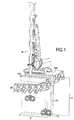
- a first step of the process consists in producing guide walls 12a, 12b for materializing the implantation of the future wall 10.
- two guide walls 12a, 12b parallel to each other, define a space of constant width 1 corresponding substantially to the width desired for the future wall.
- These guide walls 12a, 12b are generally made of reinforced concrete and have a height of about 0.5 to 1.50 meters. Their function is to ensure the stability of the surface lands, constitute leveling marks, and serve as support for holding means of the prefabricated elements, necessary during the execution of the wall and which will be described in more detail in the following with reference to the figure 3 .
- Guide walls 12a, 12b are most often temporary structures, intended to be destroyed once the wall 10 is completed.
- a trench 14, of height H and width I corresponding to those desired for the wall 10 is hollowed out vertically between the two guide walls 12a, 12b, by means of a drilling and / or mixing machine. .
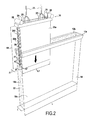
- the trench 14 has an elongated shape that extends over a length L. As illustrated in FIG. figure 2 it has two longitudinal walls 18a, 18b spaced a constant distance I, each of them extending vertically in the extension of one of the two guide walls 12a, 12b. Trench 14 marks the future location of wall 10, and delimits an area to be cleared 20.
- the trench 14 is filled, during drilling, a mud generally based on bentonite.
- the trench 14 is then filled with a self-hardening material 22 intended, as will be described with reference to the figure 2 , to coat one or more prefabricated elements, and, once solidified, to seal these prefabricated elements to the ground in place.
- the self-hardening material 22 is made by mixing a self-hardening grout, for example a cement grout, with the ground in place.
- a self-hardening grout for example a cement grout
- the drilling may be carried out with a bentonite sludge as described above, but the self-hardening material 22 consists of a cement-based grout (for example a bentonite-cement slurry) which is just filled in. the trench at the end of the drilling.
- the drilling may be carried out directly with a grout based on cement (for example a bentonite-cement grout), which constitutes the self-hardening material.
- a first prefabricated element 241 is progressively introduced into the trench 14.
- a hoist equipped with slings 23 is attached to lifting cables 25 integral with the prefabricated element.
- its lateral face oriented towards the zone to be knocked down 20 is preferably brushed with a stripping product (ie as it descends inside the trench 14). This operation can also be done before lowering the prefabricated element in the trench.
- the prefabricated element 241 comprises two concrete plates (or skins) 26a, 26b, connected and held together by metal reinforcements 28.
- the plates 26a, 26b have the same length L1, the same thickness e1 and the same height H1 . They are placed opposite one another, parallel to each other and spaced apart by a distance d1.
- the prefabricated element 241, of width I1 is thus provided with a recess 27 between its two plates 26a, 26b. Note that, in the example, the metal fittings in the recess 27 are devoid of concrete coating.
- the recess 27 is filled with the self-hardening material 22, which encapsulates the metal reinforcements 28.
- the two plates 26a, 26b of the prefabricated element may have different dimensions (width, length, thickness).
- Positioning members 29 protrude from the upper end of each plate 26a, 26b. These positioning members are, for example, threaded rods 29 whose function will be described in more detail with reference to FIG. figure 3 .
- the prefabricated element 241 comprises, at each of its lateral ends, between its two plates 26a, 26b and in contact with one of these plates, a split metal tube 32 defining a hollow housing 30.
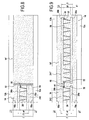
- the split tube 32 is extends substantially over the entire height H1 of the plates 26a. Its function will be described in more detail with reference to figures 4 and 5 .
- the split tube 32 is for example cast with one of the two plates 26a, 26b. According to other exemplary embodiments, it may be connected to the metal frames 28, or other metal elements connecting the two plates 26a, 26b of the prefabricated element 241, by welding. According to yet another embodiment, at least two split tubes 32, or another type of hollow housing may be provided on one or each side of the prefabricated element.
- a protective piece 34 for example a rod of suitable dimensions, is inserted into each tube 32, before the prefabricated element 241 has descended into the trench 14.
- the protective piece 34 made for example of a friable material or deformable, is intended to prevent any intrusion of material in the split tube 32 before the prefabricated element 241 is connected to an adjacent prefabricated element (this step will be described in more detail with reference to the figures 4 and 5 ).
- the protective piece 34 thus fills the split tube 32 along its entire length.
- the high density of the self-hardening material 22 makes it difficult for the prefabricated element 241 to enter the trench 14 due to its own self weight. This is generally the case when, as in the example, the self-hardening material 22 is a "soil-cement" mixture.
- the prefabricated element 241 can be vibrate, for example by means of a frame 36 provided with electric vibrators 38 positioned at its upper end during the lifting and positioning phases in the trench 14. Thanks to the vibration, the prefabricated element 241 is then easily brought up 'to its final position in trench 14.
- a fifth step the position of the prefabricated element 241 inside the trench 14 is adjusted and maintained by means of holding means as described below with reference to the figure 3 .
- each plate 26a, 26b of the prefabricated element 241 comprises positioning members in the form of a plurality of threaded rods 29 projecting from its upper face. These rods 29 extend in the direction of the height of the prefabricated element 241 and have a length sufficient to cross right through a spacer 40 bearing transversely on the guide walls 12a, 12b. The position of the prefabricated element 241 is maintained by means of nuts 42 cooperating with the threads of the rods 29, and bearing on the upper face of the spacer 40.
- the positioning members may be positioning loops provided at the upper end of the prefabricated element 241, and the holding means may be bars passed through said loops and bearing transversely on the guide walls 12a, 12b.
- the trench 14 has a length L which is substantially greater than twice that of the prefabricated element 241.
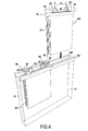
- a second prefabricated element 242 is positioned in the trench 14, next to the first prefabricated element 241.
- the lifting and insertion operations of the second prefabricated element 242 are identical in all respects to those described above with reference to the Figures 1 to 3 . They are not described again.
- the second prefabricated element 242 has, on its side facing the first prefabricated element 241, at its lower end, a metal knife 44 of complementary profile to the housing 30 formed by the split tube 32 of the first prefabricated element 241.
- the second prefabricated element 242 On its side oriented towards the first prefabricated element 241, the second prefabricated element 242 is also provided with a split tube 32 similar to that of the first prefabricated element 241. As illustrated in FIG. figure 4 a seal 46, in particular an inflatable water-stop seal, is connected to this split tube 32.
- a seal 46 "water-stop" comprises two inflatable hollow tubes 48a, 48b, and an intermediate portion 50 connecting these two flanges 48a, 48b.
- a first coil 48b is inserted into its split tube 32 intended to be oriented towards the first element 241.
- the knife 44 serves to guide and position the second prefabricated element 242 relative to the first prefabricated element 241. For this, when the second prefabricated element 242 is lowered into the adjacent free space at the first prefabricated element 241 by means of the hoist, its knife 44 is threaded into the adjacent split tube 32 of the first prefabricated element 241, until the upper faces of the two prefabricated elements 241, 242 are substantially same height. By sliding in the housing 30 formed by the slotted tube 32, the knife 44 progressively removes the protective piece 34, for example by breaking or deforming it, or by pushing it into the bottom of the trench 14.
- the knife 44 of the second prefabricated element also participates in guiding the second coil 48a in the split tube 32 of the first prefabricated element 241.
- Sealing is ensured by injecting a cement slurry into each flange 48a, 48b until it swells sufficiently to obtain a close contact between the flange and the inner wall of the slotted tube 32 in which it is positioned.
- protection elements 52 are positioned in the trench 14, facing each location provided for an adjacent trench.
- each protection element 52 is in the form of a metal profile, comprising a main plate 54 of width and height substantially equal to those of the first trench, and a connecting guide 56 connected to said plate 54 and whose arrangement and dimensions are adapted to its introduction, by sliding, in a split tube 32 of a prefabricated element 241, 242.
- the connecting guide 56 makes it possible to position and fix each profile 52 with respect to a prefabricated element 241, 242. It also has the function of preventing self-hardening material from filling the split tube 32 and starting to take hold of it, particularly in the case of an extended stoppage of the site.
- the main plate 54 makes it possible to preserve the prefabricated element 242 of the first trench 14 from any damage caused by the drilling and / or kneading machine 16 coming to excavate the adjacent trench. It can also prevent the self-hardening material 22 located in the first trench 14 and not yet solidified from mixing with the sludge or any other temporary filling material of the adjacent trench before it is filled with material. self-hardening and ready to receive the prefabricated element (s).
- a second trench 14 ' (according to the example, of the same width and height as the first trench) is drilled to the right of the first trench 14.
- the profile 52 can then be used to guide the secondary perforation by means of the machine
- the section 52 is positioned at a sufficient distance from the end of the first trench 14, so that it is re-formed during the excavation of the second trench 14. .
- a prefabricated element 241' is introduced into the second trench 14 ', following the same steps as those described with reference to the Figures 2 to 5 .
- this prefabricated element 241 ' comprises, on its side oriented towards the first trench 14, a knife 44 intended to be threaded progressively into the split tube 32 of the adjacent prefabricated element 242 of the first trench 14 (oriented to the second trench 14 ') until the upper faces of the two prefabricated elements 242, 241 are substantially at the same height.
- a seal 46 previously connected to said prefabricated element 241 'of the second trench 14' and extending substantially over its entire height, can be threaded into the split tube 32 of the second prefabricated element 242 of the first trench 14.
- the zone 20 is cleared to discover one of the faces of said wall.
- the hardened grout remains adhering to the exposed faces of the prefabricated elements are finally removed by scraping, brushing, etc.
- the width I of the wall 10 obtained according to the method described above is 600 mm
- the width I1 of the prefabricated element 241 is 400 mm
- the thickness e1 each concrete plate 26a, 26b of the prefabricated element is 70 mm.
- the percentage of the width of the wall occupied by the self-hardening material 22 is (600-2 ⁇ 70) / 600 or about 75%.
- Such provisions can limit the amount of noble material (concrete) used and thus lower costs. They also make it easier to insert the prefabricated element in a relatively dense and compact self-hardening material, especially in cases where the self-hardening material is obtained by means of a method of soil mixing.
Landscapes
- Engineering & Computer Science (AREA)
- Structural Engineering (AREA)
- Mining & Mineral Resources (AREA)
- Life Sciences & Earth Sciences (AREA)
- General Life Sciences & Earth Sciences (AREA)
- Paleontology (AREA)
- Civil Engineering (AREA)
- General Engineering & Computer Science (AREA)
- Bulkheads Adapted To Foundation Construction (AREA)
Priority Applications (1)
| Application Number | Priority Date | Filing Date | Title |
|---|---|---|---|
| PL11167120T PL2390420T3 (pl) | 2010-05-25 | 2011-05-23 | Ściana formowana w ziemi, zawierająca wydrążony element prefabrykowany i sposób wykonania takiej ściany |
Applications Claiming Priority (1)
| Application Number | Priority Date | Filing Date | Title |
|---|---|---|---|
| FR1054019A FR2960570B1 (fr) | 2010-05-25 | 2010-05-25 | Paroi formee dans un sol, comprenant un element prefabrique creux, et procede de realisation d'une telle paroi |
Publications (2)
| Publication Number | Publication Date |
|---|---|
| EP2390420A1 EP2390420A1 (fr) | 2011-11-30 |
| EP2390420B1 true EP2390420B1 (fr) | 2015-03-04 |
Family
ID=43544986
Family Applications (1)
| Application Number | Title | Priority Date | Filing Date |
|---|---|---|---|
| EP11167120.2A Active EP2390420B1 (fr) | 2010-05-25 | 2011-05-23 | Paroi formée dans un sol, comprenant un élément préfabriqué creux, et procédé de réalisation d'une telle paroi |
Country Status (7)
| Country | Link |
|---|---|
| US (1) | US9212462B2 (pl) |
| EP (1) | EP2390420B1 (pl) |
| AU (1) | AU2011202417B2 (pl) |
| ES (1) | ES2538579T3 (pl) |
| FR (1) | FR2960570B1 (pl) |
| PL (1) | PL2390420T3 (pl) |
| SG (1) | SG176392A1 (pl) |
Families Citing this family (17)
| Publication number | Priority date | Publication date | Assignee | Title |
|---|---|---|---|---|
| IT1401736B1 (it) * | 2010-07-19 | 2013-08-02 | Soilmec Spa | Dispositivo di perforazione per l'esecuzione di diaframmi e relativo metodo. |
| DE102013205765B4 (de) | 2013-04-02 | 2021-06-02 | Gud Geotechnik Und Dynamik Consult Gmbh | Qualitätssicherungssystem für Schlitzwandfugen |
| RU2673827C2 (ru) * | 2014-04-29 | 2018-11-30 | Хэллибертон Энерджи Сервисиз, Инк. | Управление торцом долота скважинного инструмента с уменьшенным трением бурильной колонны |
| JP6661448B2 (ja) * | 2016-04-05 | 2020-03-11 | 大成建設株式会社 | 地中連続壁の構築方法 |
| US10150138B1 (en) * | 2017-05-16 | 2018-12-11 | Roger Thomas Haag | Interface for inserting bonding material between the joins of two interlocking members |
| KR101796897B1 (ko) * | 2017-05-31 | 2017-12-01 | 강한주 | 지반 굴착기용 케이싱 가이드 장치 및 이를 이용한 굴착방법 |
| CN107035022A (zh) * | 2017-06-14 | 2017-08-11 | 福建建泰建筑科技有限责任公司 | 一种经现浇叠合预制砼板构建的外墙及其施工方法 |
| CN107023099A (zh) * | 2017-06-14 | 2017-08-08 | 福建建泰建筑科技有限责任公司 | 预制叠合板双拼式叠合剪力墙及其施工方法 |
| US9988823B1 (en) | 2017-10-02 | 2018-06-05 | General Steel And Supply Company | Concrete forming system |
| US10427916B1 (en) * | 2018-10-05 | 2019-10-01 | Tgr Construction, Inc. | Structure installation system with vehicle having hangers to support a wall |
| US10633812B1 (en) | 2019-06-25 | 2020-04-28 | Tgr Construction, Inc. | Bollard wall gate system |
| IT201900014193A1 (it) | 2019-08-08 | 2021-02-08 | Gardelli Manuela | dispositivo contenitore di protesi mammaria in senologia ricostruttiva |
| US10633887B1 (en) | 2019-08-29 | 2020-04-28 | Tgr Construction, Inc. | Bollard setting and installation system |
| US20230193616A1 (en) * | 2019-11-26 | 2023-06-22 | A.H. Beck Foundation Co., Inc. | Border Security Barrier |
| CN111155582B (zh) * | 2020-01-20 | 2022-07-15 | 山东土力机械科技有限公司 | 地基处理及垂直防渗处理用双轮铣削搅拌装置及施工方法 |
| US11105116B1 (en) | 2021-03-18 | 2021-08-31 | Tgr Construction, Inc. | Bollard wall system |
| CN116770813B (zh) * | 2023-06-19 | 2024-01-26 | 中铁一局集团(广州)建设工程有限公司 | 一种预制地连墙安装过程垂直度调整结构及其施工方法 |
Family Cites Families (18)
| Publication number | Priority date | Publication date | Assignee | Title |
|---|---|---|---|---|
| US745453A (en) * | 1903-05-09 | 1903-12-01 | Duncan D Mcbean | Pilot-sheeting. |
| IT1025608B (it) * | 1974-11-12 | 1978-08-30 | Alpina Spa | Elementi prefabbricati per la co struzione di strutture in trincea e procedimento relativo |
| US4005582A (en) * | 1975-08-12 | 1977-02-01 | Icos Corporation Of America | Method of constructing underground concrete walls and reinforcement cage therefor |
| US4259028A (en) * | 1978-04-17 | 1981-03-31 | Efficiency Production, Inc. | Water and debris impermeable trench box panel |
| US4290246A (en) * | 1978-11-22 | 1981-09-22 | Hilsey Arthur F | Multi-purpose precast concrete panels, and methods of constructing concrete structures employing the same |
| NL7903935A (nl) * | 1979-05-18 | 1980-11-20 | Visser & Smit Bouw Bv | Werkwijze voor het maken van een diepwandkonstruktie, alsmede volgens deze werkwijze verkregen diepwand- konstruktie. |
| DE2944385A1 (de) * | 1979-11-02 | 1981-05-14 | Josef Riepl Bau-Aktiengesellschaft, 8000 München | Verfahren zum herstellen von schlitzwaenden |
| NL8301918A (nl) * | 1983-05-31 | 1984-12-17 | Nico Gerhard Cortlever | Damwand vormende een waterdicht scherm in de grond en werkwijze voor het aanbrengen daarvan. |
| US4469194A (en) * | 1983-10-21 | 1984-09-04 | Mcbride Thomas D | Non-slip resilient ladder support |
| US5259705A (en) * | 1989-08-25 | 1993-11-09 | Breaux Louis B | Guide box assembly system for in-ground barrier installation |
| US5096334B1 (en) * | 1990-09-28 | 1998-07-14 | Speed Shore Corp | Shoring shield |
| US5758993A (en) * | 1996-06-11 | 1998-06-02 | Slurry Systems, Inc. | Method and apparatus for forming successive overlapping voids in the ground along a predetermined course of travel and for producing a subterranean wall therein |
| NL1015692C2 (nl) * | 1999-07-23 | 2001-02-06 | Ballast Nedam Funderingstechni | Werkwijze voor het vormen van een afscheiding in de grond en zo gevormde afscheiding. |
| US6240700B1 (en) * | 1999-10-12 | 2001-06-05 | Chyi Sheu | Constructing method for underground continuous double-row walls and the structure of continuous double-row walls |
| FR2804449B1 (fr) * | 2000-02-02 | 2002-12-13 | Soletanche Bachy France | Perfectionnement a la realisation de paroi drainante |
| FR2874222B1 (fr) * | 2004-08-10 | 2006-12-01 | Cie Du Sol Soc Civ Ile | Machine pour creuser une tranchee et realiser une paroi dans ladite tranchee |
| ES2294410T3 (es) * | 2004-08-12 | 2008-04-01 | Bauer Maschinen Gmbh | Metodo y dispositivo par trabajar el suelo. |
| US7785042B2 (en) * | 2006-05-24 | 2010-08-31 | Samuel Zengel Scandaliato | Double-wall protection levee system |
-
2010
- 2010-05-25 FR FR1054019A patent/FR2960570B1/fr not_active Expired - Fee Related
-
2011
- 2011-05-23 SG SG2011037082A patent/SG176392A1/en unknown
- 2011-05-23 PL PL11167120T patent/PL2390420T3/pl unknown
- 2011-05-23 ES ES11167120.2T patent/ES2538579T3/es active Active
- 2011-05-23 EP EP11167120.2A patent/EP2390420B1/fr active Active
- 2011-05-24 AU AU2011202417A patent/AU2011202417B2/en not_active Ceased
- 2011-05-25 US US13/115,821 patent/US9212462B2/en active Active
Also Published As
| Publication number | Publication date |
|---|---|
| EP2390420A1 (fr) | 2011-11-30 |
| SG176392A1 (en) | 2011-12-29 |
| US20120000148A1 (en) | 2012-01-05 |
| PL2390420T3 (pl) | 2015-08-31 |
| FR2960570B1 (fr) | 2013-06-14 |
| ES2538579T3 (es) | 2015-06-22 |
| AU2011202417A1 (en) | 2011-12-15 |
| FR2960570A1 (fr) | 2011-12-02 |
| US9212462B2 (en) | 2015-12-15 |
| AU2011202417B2 (en) | 2016-06-16 |
Similar Documents
| Publication | Publication Date | Title |
|---|---|---|
| EP2390420B1 (fr) | Paroi formée dans un sol, comprenant un élément préfabriqué creux, et procédé de réalisation d'une telle paroi | |
| EP2964837B1 (fr) | Paroi moulee precontrainte et procede de realisation d'une telle paroi | |
| CA1217349A (fr) | Procede de realisation d'ouvrages en beton arme tels que galeries souterraines, tunnels routiers, etc.; elements en beton prefabriques pour la realisation de tels ouvrages | |
| EP0081402B1 (fr) | Procédé d'obtention de structures creuses, telles que des conduites, silos ou abris. | |
| CH642416A5 (fr) | Procede de construction d'ouvrages souterrains a parois verticales, dispositif pour l'execution du procede et ouvrage souterrain. | |
| EP3146155B1 (fr) | Élément de construction pour la réalisation d'un tunnel, tunnel comprenant un tel élément et procédés de fabrication d'un tel élément et d'un tel tunnel | |
| WO1986000358A1 (fr) | Procede et appareillage pour la realisation d'une dalle rigide permettant de porter une construction | |
| EP0244890B1 (fr) | Procédé de réalisation de structures creuses, de grande section, telles que des conduites, silos ou abris, et structures obtenues par ce procédé | |
| EP0065486B1 (fr) | Ouvrage souterrain allongé de section constante et procédé de construction de cet ouvrage | |
| FR2504953A1 (fr) | Procede de construction d'une paroi secante constituee de pieux de beton et paroi secante ainsi obtenue | |
| EP2563975B1 (fr) | Paroi moulee avec parement prefabrique | |
| EP0242497A1 (fr) | Procédé pour la construction de tunnels | |
| FR2473085A1 (fr) | Procede pour assurer la continuite des armatures entre des panneaux successifs d'une paroi en beton arme, et panier d'armatures pour la mise en oeuvre de ce procede | |
| EP3201399B1 (fr) | Procédé de fabrication d'un réservoir de stockage enterré et réservoir correspondant | |
| FR2581678A1 (fr) | Procede pour la realisation d'une structure en beton arme noyee dans le sol | |
| FR2953231A1 (fr) | Procede de confortement d’un terrain et ouvrage de confortement | |
| EP3749810B1 (fr) | Fondation d'appui ponctuel de structure et procédé de construction d'une telle fondation | |
| FR3149916A1 (fr) | Procédé de construction d’une paroi enterrée à l’aide d’une brique préfabriquée en béton et brique préfabriquée en béton à cet effet | |
| EP1407085B1 (fr) | Procede et dispositif pour la realisation d'une paroi en beton arme dans le sol | |
| EP3320147B1 (fr) | Procédé de fabrication d'une fondation comportant une étape de recépage | |
| FR3143062A1 (fr) | Étui avec gaine injectable | |
| FR2634804A1 (fr) | Procede pour la mise en place d'un poteau prefabrique dans un forage de grande profondeur et poteau pour la mise en oeuvre de ce procede | |
| EP2455549A1 (fr) | Fondation en béton intégrant un ensemble de lestage | |
| BE437110A (pl) | ||
| BE893989A (fr) | Procede de realisation d'ouvrages en beton arme tels que galeries souterraines, tunnels routiers, etc. elements en beton prefabriques pour la realisation de tels ouvrages. |
Legal Events
| Date | Code | Title | Description |
|---|---|---|---|
| AK | Designated contracting states |
Kind code of ref document: A1 Designated state(s): AL AT BE BG CH CY CZ DE DK EE ES FI FR GB GR HR HU IE IS IT LI LT LU LV MC MK MT NL NO PL PT RO RS SE SI SK SM TR |
|
| AX | Request for extension of the european patent |
Extension state: BA ME |
|
| PUAI | Public reference made under article 153(3) epc to a published international application that has entered the european phase |
Free format text: ORIGINAL CODE: 0009012 |
|
| 17P | Request for examination filed |
Effective date: 20120511 |
|
| GRAP | Despatch of communication of intention to grant a patent |
Free format text: ORIGINAL CODE: EPIDOSNIGR1 |
|
| INTG | Intention to grant announced |
Effective date: 20140919 |
|
| GRAS | Grant fee paid |
Free format text: ORIGINAL CODE: EPIDOSNIGR3 |
|
| GRAA | (expected) grant |
Free format text: ORIGINAL CODE: 0009210 |
|
| AK | Designated contracting states |
Kind code of ref document: B1 Designated state(s): AL AT BE BG CH CY CZ DE DK EE ES FI FR GB GR HR HU IE IS IT LI LT LU LV MC MK MT NL NO PL PT RO RS SE SI SK SM TR |
|
| REG | Reference to a national code |
Ref country code: GB Ref legal event code: FG4D Free format text: NOT ENGLISH |
|
| REG | Reference to a national code |
Ref country code: CH Ref legal event code: EP |
|
| REG | Reference to a national code |
Ref country code: IE Ref legal event code: FG4D Free format text: LANGUAGE OF EP DOCUMENT: FRENCH |
|
| REG | Reference to a national code |
Ref country code: AT Ref legal event code: REF Ref document number: 714041 Country of ref document: AT Kind code of ref document: T Effective date: 20150415 |
|
| REG | Reference to a national code |
Ref country code: DE Ref legal event code: R096 Ref document number: 602011014257 Country of ref document: DE Effective date: 20150416 |
|
| REG | Reference to a national code |
Ref country code: RO Ref legal event code: EPE |
|
| REG | Reference to a national code |
Ref country code: ES Ref legal event code: FG2A Ref document number: 2538579 Country of ref document: ES Kind code of ref document: T3 Effective date: 20150622 |
|
| REG | Reference to a national code |
Ref country code: AT Ref legal event code: MK05 Ref document number: 714041 Country of ref document: AT Kind code of ref document: T Effective date: 20150304 Ref country code: NL Ref legal event code: VDEP Effective date: 20150304 |
|
| PG25 | Lapsed in a contracting state [announced via postgrant information from national office to epo] |
Ref country code: FI Free format text: LAPSE BECAUSE OF FAILURE TO SUBMIT A TRANSLATION OF THE DESCRIPTION OR TO PAY THE FEE WITHIN THE PRESCRIBED TIME-LIMIT Effective date: 20150304 Ref country code: LT Free format text: LAPSE BECAUSE OF FAILURE TO SUBMIT A TRANSLATION OF THE DESCRIPTION OR TO PAY THE FEE WITHIN THE PRESCRIBED TIME-LIMIT Effective date: 20150304 Ref country code: NO Free format text: LAPSE BECAUSE OF FAILURE TO SUBMIT A TRANSLATION OF THE DESCRIPTION OR TO PAY THE FEE WITHIN THE PRESCRIBED TIME-LIMIT Effective date: 20150604 Ref country code: HR Free format text: LAPSE BECAUSE OF FAILURE TO SUBMIT A TRANSLATION OF THE DESCRIPTION OR TO PAY THE FEE WITHIN THE PRESCRIBED TIME-LIMIT Effective date: 20150304 Ref country code: SE Free format text: LAPSE BECAUSE OF FAILURE TO SUBMIT A TRANSLATION OF THE DESCRIPTION OR TO PAY THE FEE WITHIN THE PRESCRIBED TIME-LIMIT Effective date: 20150304 |
|
| REG | Reference to a national code |
Ref country code: LT Ref legal event code: MG4D |
|
| PG25 | Lapsed in a contracting state [announced via postgrant information from national office to epo] |
Ref country code: GR Free format text: LAPSE BECAUSE OF FAILURE TO SUBMIT A TRANSLATION OF THE DESCRIPTION OR TO PAY THE FEE WITHIN THE PRESCRIBED TIME-LIMIT Effective date: 20150605 Ref country code: LV Free format text: LAPSE BECAUSE OF FAILURE TO SUBMIT A TRANSLATION OF THE DESCRIPTION OR TO PAY THE FEE WITHIN THE PRESCRIBED TIME-LIMIT Effective date: 20150304 Ref country code: RS Free format text: LAPSE BECAUSE OF FAILURE TO SUBMIT A TRANSLATION OF THE DESCRIPTION OR TO PAY THE FEE WITHIN THE PRESCRIBED TIME-LIMIT Effective date: 20150304 Ref country code: AT Free format text: LAPSE BECAUSE OF FAILURE TO SUBMIT A TRANSLATION OF THE DESCRIPTION OR TO PAY THE FEE WITHIN THE PRESCRIBED TIME-LIMIT Effective date: 20150304 |
|
| REG | Reference to a national code |
Ref country code: PL Ref legal event code: T3 |
|
| PG25 | Lapsed in a contracting state [announced via postgrant information from national office to epo] |
Ref country code: NL Free format text: LAPSE BECAUSE OF FAILURE TO SUBMIT A TRANSLATION OF THE DESCRIPTION OR TO PAY THE FEE WITHIN THE PRESCRIBED TIME-LIMIT Effective date: 20150304 |
|
| PG25 | Lapsed in a contracting state [announced via postgrant information from national office to epo] |
Ref country code: SK Free format text: LAPSE BECAUSE OF FAILURE TO SUBMIT A TRANSLATION OF THE DESCRIPTION OR TO PAY THE FEE WITHIN THE PRESCRIBED TIME-LIMIT Effective date: 20150304 Ref country code: PT Free format text: LAPSE BECAUSE OF FAILURE TO SUBMIT A TRANSLATION OF THE DESCRIPTION OR TO PAY THE FEE WITHIN THE PRESCRIBED TIME-LIMIT Effective date: 20150706 Ref country code: EE Free format text: LAPSE BECAUSE OF FAILURE TO SUBMIT A TRANSLATION OF THE DESCRIPTION OR TO PAY THE FEE WITHIN THE PRESCRIBED TIME-LIMIT Effective date: 20150304 Ref country code: CZ Free format text: LAPSE BECAUSE OF FAILURE TO SUBMIT A TRANSLATION OF THE DESCRIPTION OR TO PAY THE FEE WITHIN THE PRESCRIBED TIME-LIMIT Effective date: 20150304 |
|
| PG25 | Lapsed in a contracting state [announced via postgrant information from national office to epo] |
Ref country code: IS Free format text: LAPSE BECAUSE OF FAILURE TO SUBMIT A TRANSLATION OF THE DESCRIPTION OR TO PAY THE FEE WITHIN THE PRESCRIBED TIME-LIMIT Effective date: 20150704 |
|
| REG | Reference to a national code |
Ref country code: DE Ref legal event code: R119 Ref document number: 602011014257 Country of ref document: DE |
|
| REG | Reference to a national code |
Ref country code: HU Ref legal event code: AG4A Ref document number: E024921 Country of ref document: HU |
|
| PG25 | Lapsed in a contracting state [announced via postgrant information from national office to epo] |
Ref country code: IT Free format text: LAPSE BECAUSE OF FAILURE TO SUBMIT A TRANSLATION OF THE DESCRIPTION OR TO PAY THE FEE WITHIN THE PRESCRIBED TIME-LIMIT Effective date: 20150304 |
|
| REG | Reference to a national code |
Ref country code: CH Ref legal event code: PL |
|
| PLBE | No opposition filed within time limit |
Free format text: ORIGINAL CODE: 0009261 |
|
| STAA | Information on the status of an ep patent application or granted ep patent |
Free format text: STATUS: NO OPPOSITION FILED WITHIN TIME LIMIT |
|
| PG25 | Lapsed in a contracting state [announced via postgrant information from national office to epo] |
Ref country code: LU Free format text: LAPSE BECAUSE OF FAILURE TO SUBMIT A TRANSLATION OF THE DESCRIPTION OR TO PAY THE FEE WITHIN THE PRESCRIBED TIME-LIMIT Effective date: 20150523 Ref country code: LI Free format text: LAPSE BECAUSE OF NON-PAYMENT OF DUE FEES Effective date: 20150531 Ref country code: CH Free format text: LAPSE BECAUSE OF NON-PAYMENT OF DUE FEES Effective date: 20150531 Ref country code: DK Free format text: LAPSE BECAUSE OF FAILURE TO SUBMIT A TRANSLATION OF THE DESCRIPTION OR TO PAY THE FEE WITHIN THE PRESCRIBED TIME-LIMIT Effective date: 20150304 Ref country code: MC Free format text: LAPSE BECAUSE OF FAILURE TO SUBMIT A TRANSLATION OF THE DESCRIPTION OR TO PAY THE FEE WITHIN THE PRESCRIBED TIME-LIMIT Effective date: 20150304 |
|
| 26N | No opposition filed |
Effective date: 20151207 |
|
| REG | Reference to a national code |
Ref country code: IE Ref legal event code: MM4A |
|
| PG25 | Lapsed in a contracting state [announced via postgrant information from national office to epo] |
Ref country code: SI Free format text: LAPSE BECAUSE OF FAILURE TO SUBMIT A TRANSLATION OF THE DESCRIPTION OR TO PAY THE FEE WITHIN THE PRESCRIBED TIME-LIMIT Effective date: 20150304 |
|
| REG | Reference to a national code |
Ref country code: FR Ref legal event code: PLFP Year of fee payment: 6 |
|
| PG25 | Lapsed in a contracting state [announced via postgrant information from national office to epo] |
Ref country code: DE Free format text: LAPSE BECAUSE OF NON-PAYMENT OF DUE FEES Effective date: 20151201 Ref country code: IE Free format text: LAPSE BECAUSE OF NON-PAYMENT OF DUE FEES Effective date: 20150523 |
|
| PG25 | Lapsed in a contracting state [announced via postgrant information from national office to epo] |
Ref country code: MT Free format text: LAPSE BECAUSE OF FAILURE TO SUBMIT A TRANSLATION OF THE DESCRIPTION OR TO PAY THE FEE WITHIN THE PRESCRIBED TIME-LIMIT Effective date: 20150304 |
|
| REG | Reference to a national code |
Ref country code: FR Ref legal event code: PLFP Year of fee payment: 7 |
|
| PG25 | Lapsed in a contracting state [announced via postgrant information from national office to epo] |
Ref country code: SM Free format text: LAPSE BECAUSE OF FAILURE TO SUBMIT A TRANSLATION OF THE DESCRIPTION OR TO PAY THE FEE WITHIN THE PRESCRIBED TIME-LIMIT Effective date: 20150304 Ref country code: BG Free format text: LAPSE BECAUSE OF FAILURE TO SUBMIT A TRANSLATION OF THE DESCRIPTION OR TO PAY THE FEE WITHIN THE PRESCRIBED TIME-LIMIT Effective date: 20150304 |
|
| PG25 | Lapsed in a contracting state [announced via postgrant information from national office to epo] |
Ref country code: CY Free format text: LAPSE BECAUSE OF FAILURE TO SUBMIT A TRANSLATION OF THE DESCRIPTION OR TO PAY THE FEE WITHIN THE PRESCRIBED TIME-LIMIT Effective date: 20150304 |
|
| PG25 | Lapsed in a contracting state [announced via postgrant information from national office to epo] |
Ref country code: BE Free format text: LAPSE BECAUSE OF NON-PAYMENT OF DUE FEES Effective date: 20150531 |
|
| PGFP | Annual fee paid to national office [announced via postgrant information from national office to epo] |
Ref country code: GR Payment date: 20170725 Year of fee payment: 12 |
|
| PGFP | Annual fee paid to national office [announced via postgrant information from national office to epo] |
Ref country code: PL Payment date: 20170424 Year of fee payment: 7 |
|
| PGFP | Annual fee paid to national office [announced via postgrant information from national office to epo] |
Ref country code: HU Payment date: 20170516 Year of fee payment: 7 |
|
| REG | Reference to a national code |
Ref country code: FR Ref legal event code: PLFP Year of fee payment: 8 |
|
| PG25 | Lapsed in a contracting state [announced via postgrant information from national office to epo] |
Ref country code: MK Free format text: LAPSE BECAUSE OF FAILURE TO SUBMIT A TRANSLATION OF THE DESCRIPTION OR TO PAY THE FEE WITHIN THE PRESCRIBED TIME-LIMIT Effective date: 20150304 |
|
| PG25 | Lapsed in a contracting state [announced via postgrant information from national office to epo] |
Ref country code: AL Free format text: LAPSE BECAUSE OF FAILURE TO SUBMIT A TRANSLATION OF THE DESCRIPTION OR TO PAY THE FEE WITHIN THE PRESCRIBED TIME-LIMIT Effective date: 20150304 |
|
| PG25 | Lapsed in a contracting state [announced via postgrant information from national office to epo] |
Ref country code: HU Free format text: LAPSE BECAUSE OF NON-PAYMENT OF DUE FEES Effective date: 20180524 |
|
| PG25 | Lapsed in a contracting state [announced via postgrant information from national office to epo] |
Ref country code: RO Free format text: LAPSE BECAUSE OF NON-PAYMENT OF DUE FEES Effective date: 20180523 |
|
| PG25 | Lapsed in a contracting state [announced via postgrant information from national office to epo] |
Ref country code: PL Free format text: LAPSE BECAUSE OF NON-PAYMENT OF DUE FEES Effective date: 20180523 |
|
| P01 | Opt-out of the competence of the unified patent court (upc) registered |
Effective date: 20230528 |
|
| PGFP | Annual fee paid to national office [announced via postgrant information from national office to epo] |
Ref country code: GB Payment date: 20250423 Year of fee payment: 15 Ref country code: ES Payment date: 20250602 Year of fee payment: 15 |
|
| PGFP | Annual fee paid to national office [announced via postgrant information from national office to epo] |
Ref country code: FR Payment date: 20250423 Year of fee payment: 15 |
|
| PGFP | Annual fee paid to national office [announced via postgrant information from national office to epo] |
Ref country code: TR Payment date: 20250429 Year of fee payment: 15 |