EP2386478B1 - Control of a waterjet propelled vessel - Google Patents
Control of a waterjet propelled vessel Download PDFInfo
- Publication number
- EP2386478B1 EP2386478B1 EP11176081A EP11176081A EP2386478B1 EP 2386478 B1 EP2386478 B1 EP 2386478B1 EP 11176081 A EP11176081 A EP 11176081A EP 11176081 A EP11176081 A EP 11176081A EP 2386478 B1 EP2386478 B1 EP 2386478B1
- Authority
- EP
- European Patent Office
- Prior art keywords
- heading
- watercraft
- vessel
- sensor
- acquired
- Prior art date
- Legal status (The legal status is an assumption and is not a legal conclusion. Google has not performed a legal analysis and makes no representation as to the accuracy of the status listed.)
- Active
Links
- 238000000034 method Methods 0.000 claims abstract description 73
- 238000004364 calculation method Methods 0.000 claims description 6
- 230000035939 shock Effects 0.000 claims description 4
- 238000005259 measurement Methods 0.000 description 17
- 230000008859 change Effects 0.000 description 13
- 230000007935 neutral effect Effects 0.000 description 11
- 230000001276 controlling effect Effects 0.000 description 10
- 230000004913 activation Effects 0.000 description 8
- 230000000694 effects Effects 0.000 description 8
- 230000008569 process Effects 0.000 description 8
- XLYOFNOQVPJJNP-UHFFFAOYSA-N water Substances O XLYOFNOQVPJJNP-UHFFFAOYSA-N 0.000 description 7
- 230000005672 electromagnetic field Effects 0.000 description 5
- 230000000977 initiatory effect Effects 0.000 description 5
- 230000003466 anti-cipated effect Effects 0.000 description 4
- 238000012937 correction Methods 0.000 description 4
- 230000009471 action Effects 0.000 description 3
- 230000003111 delayed effect Effects 0.000 description 3
- 230000004044 response Effects 0.000 description 3
- 230000000875 corresponding effect Effects 0.000 description 2
- 230000001419 dependent effect Effects 0.000 description 2
- 238000001914 filtration Methods 0.000 description 2
- 230000007774 longterm Effects 0.000 description 2
- 238000005086 pumping Methods 0.000 description 2
- 230000002829 reductive effect Effects 0.000 description 2
- 230000001105 regulatory effect Effects 0.000 description 2
- 230000002441 reversible effect Effects 0.000 description 2
- 230000035945 sensitivity Effects 0.000 description 2
- 238000012360 testing method Methods 0.000 description 2
- 230000001052 transient effect Effects 0.000 description 2
- 241000251468 Actinopterygii Species 0.000 description 1
- 208000032365 Electromagnetic interference Diseases 0.000 description 1
- 230000003213 activating effect Effects 0.000 description 1
- 230000002411 adverse Effects 0.000 description 1
- 230000008901 benefit Effects 0.000 description 1
- 230000002596 correlated effect Effects 0.000 description 1
- 230000003247 decreasing effect Effects 0.000 description 1
- 230000010354 integration Effects 0.000 description 1
- 230000000670 limiting effect Effects 0.000 description 1
- 230000007246 mechanism Effects 0.000 description 1
- 238000003032 molecular docking Methods 0.000 description 1
- 238000013519 translation Methods 0.000 description 1
Images


Classifications
-
- B—PERFORMING OPERATIONS; TRANSPORTING
- B63—SHIPS OR OTHER WATERBORNE VESSELS; RELATED EQUIPMENT
- B63H—MARINE PROPULSION OR STEERING
- B63H25/00—Steering; Slowing-down otherwise than by use of propulsive elements; Dynamic anchoring, i.e. positioning vessels by means of main or auxiliary propulsive elements
- B63H25/02—Initiating means for steering, for slowing down, otherwise than by use of propulsive elements, or for dynamic anchoring
- B63H25/04—Initiating means for steering, for slowing down, otherwise than by use of propulsive elements, or for dynamic anchoring automatic, e.g. reacting to compass
-
- B—PERFORMING OPERATIONS; TRANSPORTING
- B63—SHIPS OR OTHER WATERBORNE VESSELS; RELATED EQUIPMENT
- B63H—MARINE PROPULSION OR STEERING
- B63H25/00—Steering; Slowing-down otherwise than by use of propulsive elements; Dynamic anchoring, i.e. positioning vessels by means of main or auxiliary propulsive elements
- B63H25/46—Steering or dynamic anchoring by jets or by rudders carrying jets
Definitions
- the present invention relates to the control of a water jet propelled vessel.
- Such waterjet propelled vessels are known and can range in size from small personal watercraft to boats of up to 75 feet in length, or vessels of even larger size.
- a waterjet-powered vessel is moved through the water by accelerating a stream of water through a nozzle, thereby moving the vessel in reaction to the accelerated stream of water.
- the nozzle can be fixed to the rear of the vessel and aimed to produce lateral forces on the vessel which are used to steer the vessel.
- the waterjet is either engaged and pumping water or not engaged and not pumping water. Multiple waterj ets/nozzles can also be used.
- the nozzle at the rear of the vessel is also usually equipped with a reversing bucket which, when activated, redirects some or all of the nozzle flow to produce a reversed component of thrust on the vessel.
- a waterjet thruster can also be positioned in or near the bow of the vessel with its axis essentially perpendicular to the vessel's bow-stern axis to produce lateral forces at the bow of the vessel.
- the rear nozzle, reversing bucket and bow thruster can be used to simultaneously maneuver the watercraft in any desired direction or heading.
- the vessel can be equipped with a multi-axis joystick that allows the operator to simultaneously control the nozzle angle, reverse bucket position, and bow thrusters. Forward and aft movement of the joystick activates the reverse bucket. Sideways movement of the joystick activates the bow thruster, and nozzle angle is controlled by a twisting movement of the j oystick.
- U.S. Patent No. 6,234,100 to Fadeley discloses a Stick Control System For Waterjet Boats and U.S. Patent No. 6,230,642 to McKenney, dated May 15, 2001 discloses an Autopilot Based Steering And Maneuvering System For Boats.
- U.S. Patent Application No. 2003/0054707 to Morvillo discloses an Integral Reversing And Trim Deflector And Control Mechanism and
- U.S. Patent Application No. 2003/0079668 to Morvillo, dated May 1, 2003 discloses a Method And Apparatus For Controlling A Waterjet Driven Marine Vessel.
- the document EP 1 365 301 is considered to be the closest prior art and discloses a track-keeping method for movable objects based on deviations of headings calculated with a reference to the destination point.
- a first embodiment includes acquiring a desired heading of the watercraft, acquiring an actual heading of the watercraft at time To, calculating a heading error by comparing the desired heading with the actual heading, determining a rate of change of the heading error and determining a P gain, I gain and D gain for use in maintaining the heading of the watercraft.
- Dterm T 0 D * Rate of Change of Heading Error
- a value for Control OutT o is then determined by summing the values for PtermT o , ItermT o , and DtermT o and then an amount of deflection for a nozzle of the watercraft is determined, for altering a heading of the watercraft, based on the value for Control OutT o .
- the nozzle is deflected based on the determined amount of deflection and the T o to T o+i are reset with the steps being repeated until the actual heading equals the desired heading.
- a second embodiment for calculating a heading of a watercraft includes acquiring a heading of the watercraft at a base time, acquiring a heading turn rate from an angular rate of turn sensor of the watercraft at a later time and determining whether the acquired heading is believed accurate at the later time. If the acquired heading is believed inaccurate, a heading of the watercraft is calculated by adding a factor for the heading turn rate to the acquired heading and the calculated heading output for control of the heading of the watercraft.
- a further embodiment for correcting a heading of a watercraft includes measuring an amount of error induced by the effect of at least one disturbance on at least one of x, y and z heading data from a heading sensor, acquiring at least one of x, y and z heading data from a heading sensor, determining whether the at least one disturbance is occurring, correcting the heading data in the occurrence of a disturbance by adding a factor to the heading that offsets the measured amount of error induced by the disturbance and outputting the corrected heading data for control of the heading of the watercraft.
- a further embodiment for controlling roll out of a watercraft includes determining whether a nozzle control apparatus is off center to alter a position of a nozzle of the watercraft and if the nozzle control apparatus is off center, setting a nozzle control command to a nozzle control apparatus command, determining whether the nozzle control apparatus has been returned to a center position, determining a heading rate for the watercraft and if the nozzle control apparatus has been returned to a center position, setting a nozzle control command to a negative of the heading rate multiplied by a constant factor predetermined for the watercraft based on operating data of the watercraft.
- a further embodiment for controlling a watercraft having a rear nozzle for propulsion and a bow thruster includes, during at least one of initiation and cessation of sideways movement of the watercraft, prepositioning an angle of the rear nozzle to provide a sideways force that minimizes vessel yaw prior to the occurrence of a heading error, the prepositioned angle based on the operating characteristics of the watercraft.
- a further embodiment for controlling a watercraft having a rear nozzle for propulsion and a bow thruster includes initiating a sideways movement of the watercraft by engaging the rear nozzle while delaying engagement of the bow thruster and engaging the bow thruster after a first predetermined time delay to assist in the sideways movement of the watercraft after a stern of the watercraft has gained sideways momentum from the rear nozzle, the first predetermined time delay based on the operating characteristics of the watercraft to minimize yaw of the watercraft during the sideways movement.
- a further embodiment for the control of a watercraft having a magnetic sensor for determining a heading of the watercraft includes reducing the effect of electro-magnetic field interference from electrical equipment of the watercraft on the accuracy of a heading signal from the magnetic sensor controlling use of the heading signal based on at least one of a function mode of the watercraft and a position of a vessel movement control apparatus by at least one of: compensating for the field interference and acquiring the heading signal only when electro-magnetic interference is sufficiently low to prevent substantive inaccuracy of the heading data.
- the present invention includes several control methods for controlling the waterjet propelled vessel. These methods can be used individually or in combination with one or more of the other control methods to control the vessel. In the preferred embodiment, the control system will include several or all of the various control methods.
- control methods can be incorporated in the controller that controls activation of the nozzle, reversing bucket and bow thruster of the vessel and when used, will operate as described below, and can do this taking into account operator input, vessel movement data and other collected data or desired operating parameters. In all methods, alternate thrusting devices can also be used. The methods can be used with watercraft having one or more nozzle and reversing bucket sets, controllable in unison or independently.
- the control system maintains proper vessel heading at all speeds without operator intervention.
- the control method compares the desired heading to the actual heading and deflects the nozzle to correct the error.
- the controller automatically maintains the vessel heading by simultaneously controlling all propulsors, including bow thrusters, and thrust vectoring devices such as waterj ets.
- the desired heading is acquired. This can either be input into the system or captured by the system based on a heading at a specific acquisition time.
- the actual heading is acquired at step 10. In a preferred embodiment, this is acquired from a three axis heading sensor hard-mounted to the vessel and connected to the electronic controller.
- the sensor has three axes, each of which uses a magneto-inductive sensor that measures the earth's magnetic field. Because the heading sensor is hard-mounted to the vessel and the vessel is subject to pitch and roll movements from waves, the signal from the heading sensor may be adversely affected. To correct this condition, a pitch and roll sensor mounted to the vessel can be used to measure pitch and roll and provide a signal indicating the pitch and roll to the controller to enable correction of the heading signal. Other types of heading sensors can also be used.
- the heading error is calculated at step 12 by subtracting the actual heading from the desired heading. Since the vessel dynamics are different depending on whether the bow thruster is active, it is then determined whether the bow thruster is active or not at step 14.
- This control method controls vessel steering by means of an algorithm that utilizes the heading error (the difference between the desired heading and the actual heading) in such a way as to maintain a heading.
- This algorithm is comprised of the sum of three terms. One term is proportional to the heading error, one term is proportional to the heading error that has accumulated over time, and the last term is proportional to the rate-of-change of the heading error. The result of this summation is used to position the steering device. Each summation term has a multiplier associated with it, which determines that terms' effect on the overall output. These multipliers are often referred to as gains. The first gain is the "P" gain. This is sometimes referred to as rudder gain, since this gain controls how much of the heading error gets applied to the position of the steering device.
- the second gain is the "I" gain. This is sometimes referred to as trim, since it effectively adds an offset to the center position of the steering device over time. This eliminates any long-term heading offset due to wind and waves.
- the third gain is the "D" gain. This is sometimes referred to as counter-rudder. This term causes the steering device to position itself proportional to the rate of turn of the vessel, in the direction that opposes the rate of turn. Other control methods or rules can also be used.
- gain values would generally be set higher to produce sufficiently correcting control of the nozzle.
- the gain magnitudes would be set lower since the vessel is more sensitive to changes at the nozzle than at lower speeds.
- the different curves for each factor can be determined through use of empirical data or through theoretical calculation and can be modified for the dynamics of a specific vessel.
- the method can take into account other states of the vessel's positioning and propulsing systems, e.g., thruster pushing port, thruster pushing starboard, bucket position, operating mode, and operator's control interface position, all of which are not shown on the logic flow chart.
- PtermTo, ItermTo and DtermT 0 are calculated based on the "P", "I” and “D” data selected in step 16.
- PtermT o is calculated by multiplying "P” by the heading error.
- ItermT o is calculated by adding the previous iteration/time period Iterm (ItermT o-1 ) to the factor “I" times Heading Error times (To - T O-1 ).
- DtermT 0 is calculated by multiplying "D" times the rate of change of the heading error (determined by comparing the current heading error with the heading error from the previous time period and dividing by (To - T O-1 )). Once these terms have all been calculated, they are summed together at step 20 to arrive at Control OutT o , which is the signal used to control the amount of deflection of the nozzle in the desired direction.
- steps 22 and 24 following step 20 the amount of nozzle deflection and the maximum rate of nozzle deflection indicated by step 20 can be limited based on engine rpm. As engine rpm increases, the effect of the deflection of the nozzle increases. Therefore, these limitations imposed at steps 22 and 24 prevent deflection of the nozzle at too large of an angle or rate of change of angle that might allow the vessel to become unstable or feel unstable to the operator.
- the signal, whether limited or not in steps 22 and 24 is then output for the control of the nozzle at step 26.
- This signal can be a direct signal to the nozzle actuator or can be used to signal another component that controls the nozzle actuator.
- the cycle then repeats at step 28, returning to the top of the loop. In one embodiment, this cycle repeats approximately 20 times per second but this frequency can be altered as desired.
- This control method allows the vessel to be maintained accurately on a desired heading without further input from the vessel operator by adjusting the deflection of the nozzle based on the data selected. It includes limiting factors that prevent heading correction from happening too rapidly that the vessel becomes unstable or the passengers become uncomfortable.
- This method can be embodied as hardware, software or a combination of the two. It can be incorporated into an existing navigational controller for the vessel or can be a stand alone component. Other thrust vectoring devices can be used, for example, the rudder.
- One advantage of this method is that the operator doesn't have to fidget with the autopilot interface to adjust sensitivity when changing speed. Also, when tying up the vessel, the operator doesn't have to worry about the vessel twisting in the slip. Nor does the operator have to worry about vessel twisting when activating the bow thruster.
- the heading sensor can be in the form of 1) a three-axis magnetic heading sensor, occasionally referred to as a strap-down heading sensor, preferably used in conjunction with a pitch and roll sensor as discussed above for error correction; 2) a gimbaled type sensor; 3) a Global Positioning System and/or another type of heading sensor/system.
- the current method uses an angular rate of turn sensor, such as a gyro type sensor, to produce a signal, used in conjunction with the data from the heading sensor, to calculate the actual heading if it is determined that the heading data provided by the heading sensor is not likely to be reflecting the actual heading, or between heading updates (as in a GPS system).
- an angular rate of turn sensor such as a gyro type sensor
- the signal from a heading sensor is being filtered and is not reflective of the actual heading, see Fig.2 .
- the heading data is calculated using heading turn rate data.
- the heading is acquired from the heading sensor at time To, step 30.
- the Calculated HeadingT o Heading Sensor HeadingT o , step 32.
- the heading turn rate is then acquired from an angular rate of turn sensor at time T o+1 , step 34. It is then determined whether the heading turn rate is above or below a predetermined threshold at step 36. If it is below the threshold, it is assumed that the turn is not being made so fast that the data from the heading sensor is likely to be inaccurate.
- the heading sensor headingT o is output to whatever control method or mode needs such data at step 38, the time T 0 is reset at step 40 and a new iteration can start at step 30. If the heading turn rate is above the threshold at step 36 such that it is believed that the heading from the heading sensor may be inaccurate, a calculated heading is calculated at step 42 and the calculated heading is output to whatever control method or mode needs such data at step 44. Then, the time T 0 is reset at step 46 and a new iteration can start at step 34. When the heading turn rate falls below the predetermined threshold, the calculated heading portion of the loop will be left at step 38 and the process returns to the top of the flow chart, as discussed above.
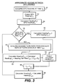
- a similar method can be used in a system where GPS data is being used to provide heading data. See Fig. 3 .
- the GPS data may not update sufficiently fast to provide the required heading data. Therefore, between updates, the heading data is again calculated using heading turn rate data.
- the GPS heading is acquired at time To, step 50.
- the heading turn rate is acquired from an angular rate of turn sensor at time T O+1 , step 60.
- a calculated heading is calculated at step 62 and the calculated heading is output at step 64.
- the time T 0 is reset at step 66, the calculated heading reset at step 68 and the process returns to step 56 to determine whether a new GPS update is available. If not, a new iteration of the bottom loop is performed. If so, the process leaves the bottom loop and returns to the top of the flow chart.
- the heading sensor can also be vulnerable to disturbances that affect its output so that the output does not reflect the actual heading.
- a magnetic heading sensor is very sensitive to magnetic disturbances that can be caused by operation of equipment on the vessel.
- the gimbaled type sensor can be sensitive to shock or vibration of the vessel, which can affect the accuracy of its output.
- the existence of such a disturbance can be determined by measurement, such as with a vibration/shock sensor measuring an amount of vibration/shock.
- the existence of a disturbance can also be assumed when one or more predetermined conditions are met. For instance, in one embodiment, it is assumed that a disturbance is occurring when electrical equipment is operating, thereby causing a magnetic interference with a magnetic heading sensor.
- the controller can be signaled when such equipment is operating so that it can take corrective action. This method provides a way for correcting the negative effect of the disturbance on the heading data.
- a heading is acquired at step 70 and a calculated heading is set to be the acquired heading at step 72. It is then determined whether a disturbance has occurred at step 74. If not, the heading acquired from the heading sensor is assumed to be accurate and is output at step 76. The process then returns to the top of the flow chart. If a disturbance is determined to be occurring so that a newly acquired heading is not believed to be accurate at time T o+1 , the heading turn rate is acquired from an angular rate of turn sensor at time T o+1 , step 80. A calculated heading is calculated at step 82 and the calculated heading is output at step 84.
- step 86 the time T 0 is reset at step 86, the calculated heading reset at step 88 and the process returns to step 74 to determine whether a disturbance is still occurring. If so, a new iteration of the bottom loop is performed. If not, the process leaves the bottom loop at step 76 and returns to the top of the flow chart.
- This embodiment can be used for different types of disturbances and different types of heading sensors.
- Magnetic disturbances can be dealt with in a specific manner.
- the magnetic heading sensor is very sensitive to magnetic disturbances that can be caused by operation of equipment on the vessel (such as electric motors, solenoids, thrusters, fish finders and pumps).
- the discovery of this sensitivity led to the introduction of a rate of turn sensor that is immune to the magnetic disturbances.
- the controller adjusts the emphasis (weighting) given any effected sensor as required to minimize such magnetic disturbances. In this manner, the controller can preemptively change gains and select the proper sensor based on a priori knowledge or measurement of the disturbances caused by the use of high-EM disturbance devices.
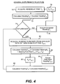
- Fig. 5 One embodiment of this method used specifically for magnetic disturbances is shown in Fig. 5 .
- This embodiment is similar to the flow chart in Fig. 1 , but where that flow chart determines whether the bow thruster is active, the present flow chart determines whether a magnetic disturbance is occurring.
- the heading from the heading sensor is acquired at step 90 and a heading error is calculated at step 92.
- the occurrence of a disturbance is determined at step 94. If no disturbance is present, the "P", “I” and “D” factors are not altered, step 96a. If a disturbance is occurring, the "P", “I” and “D” factors are weighted differently in step 96b than in step 96a.
- the "D” factor is the derivative factor, proportional to a rate of change of the heading error. It is derived from the rate sensor and not from the magnetic sensor.
- the weighting for this "D” factor is desirably increased in the presence of a magnetic disturbance, while the weighting for the "P" and “I” factors should be decreased since they are derived from a magnetic source. This is shown at step 96b.
- the Pterm, Iterm and Dterm are then calculated at step 98, the Control Out calculated at step 100 and the resulting signal is used to control the nozzle at step 102, whereupon the time is reset and a new iteration begins.
- these magnetic disturbances are transient in nature, such as the activation of a bucket solenoid, they primarily affect the "D" factor discussed above.
- the controller adds an offset to any effected axis as required to negate such magnetic disturbances. This offset is based on measurement of the disturbances during initial system setup. In some cases (e.g. where only one axis is affected by the disturbance) that axis is calculated from the other two axis measurements. Therefore, the algorithm includes a system programmed to automatically account for any electro-magnetic disturbances.
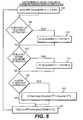
- FIG. 6 Another embodiment is shown in Fig. 6 .
- the occurrence of a condition is assumed to create a disturbance and the heading data is corrected based on predetermined knowledge of the effect of such a disturbance on the heading data.
- the magnetic X, Y and Z data are first acquired at step 106.
- step 108 it is determined whether the bucket up solenoid has been activated. If not, the process proceeds to step 112. If so, it has been previously determined, through testing, that a specific error is introduced into the Y axis measurement. Therefore, the Y axis measurement is corrected at step 110 by adding an offset to the acquired Y axis measurement which has previously been determined to offset the effect of the solenoid activation.
- step 116 it is determined whether the bow thruster has been activated. If not, the heading can be calculated at step 120 from the acquired X and Z axis measurements and the Y axis measurement, whether acquired from step 106 or corrected at steps 110 or 114. If the bow thruster has been activated, the Z axis measurement is corrected at step 118 by a formula predetermined to best correct for error introduced by the activation of the bow thruster. The heading is then calculated at step 120 with the corrected Z axis measurement. Other disturbances can also be included in this method with corrections to the factors being determined by previous testing, hypothesis and/or measurement.
- the controller senses the vessel's rate of turn during rollout, and optionally before roll out is commenced, and the nozzle is automatically deflected proportional to the rate of turn, to oppose the turn.
- the nozzle position is continuously updated with the rate of turn throughout the rollout. This results in a quicker, more repeatable response time to end a turn.
- the control system acquires the new heading. Since the vessel is not turning and the nozzle is at neutral, there is no overshoot.
- the Nozzle Position Command for this control method is zero, step 130. That means that this control method is not altering the nozzle position, whether the nozzle position is neutral or turned.
- step 132 it is determined whether the control stick is off-center, that is, the operator is making a turn. If not, the control method returns to step 132.
- This can include a joystick system where the joystick is rotated in the desired direction to steer the vessel in that direction and can also include a joystick system where the joystick is moved to the desired side (without rotation) to steer the vessel in the desired direction.
- Other steering controls can also be used without altering the applicability of this control method, or other control methods discussed herein.
- the query as to whether the stick is off-center is merely querying whether the operator is operating the steering control, of whatever type, to steer the vessel.
- the Nozzle Position Command is set as the Stick Position Command at step 134 so that the nozzle position is directly correlated to the stick position (ignoring adjustments to the nozzle position by other control methods).
- the Heading Sensor Filtering if any, is then reduced at step 136 and it is then determined at step 138 whether the stick has returned to center or not. If not, the control method returns to step 134.
- the Nozzle Position Command is set as the negative of the Heading Rate multiplied by a constant factor k.
- the Heading Rate can be determined from a calculation of the change in heading over time or can come from a Heading Rate Sensor.
- the constant k can be a specific constant determined for the particular vessel or can be accessed from a chart depending on other factors. It is only at step 140 that this control method actually sends a signal that is used to adjust the position of the nozzle from where it would be if this control method were not in operation.
- step 142 It is then again determined whether the stick is off center at step 142. If so, for instance, because the operator may be making a slight adjustment to the heading, the control method returns to step 134. If the stick is still at center, it is determined at step 144 whether the Heading Rate is less than a predetermined threshold. Below this threshold, the vessel is turning at a slow enough rate to restore any filtering that was reduced in step 136.
- the control method returns to step 140. If the Heading Rate is below the threshold, the Heading Sensor Filters are restored at step 148 and it is determined whether the Heading Rate is below a second, lower threshold at step 152. Here, it is being determined whether the vessel has stopped turning. Although this would indicate that the Heading Rate should be zero, it has been found that because of noise, the Heading Rate may not indicate zero even when the vessel is not turning. Therefore, it is determined whether the Heading Rate is below a threshold that would allow for the noise but still be a good indicator that no turning is occurring or that it is at a very low rate. If below this lower predetermined threshold, it is assumed that the vessel has stopped turning, and the control method returns to the top of the logic flow chart at step 130. If the Heading Rate is above the lower threshold, the vessel may still be turning and the control method returns to step 140.
- the controller can also remember the amount of nozzle trim/offset (necessary to maintain a heading) in place before the operator twists the stick, and return the nozzle to that offset as the stick is returned to neutral.
- the bow when initiating a sideways movement, the bow already has significant sideways momentum by the time the autopilot-initiated nozzle movement occurs. This results in an unanticipated vessel yaw because there is sideways propulsion from the bow thruster at the bow of the vessel but no sideways propulsion yet at the stern of the vessel from the nozzle.
- one aspect of the current invention uses pre-emptive, feed-forward (i.e., before heading feedback changes) algorithms that pre-position control elements in anticipation of the heading error that will develop due to the above factors. If sideways movement is being initiated, the nozzle is moved to an appropriate predetermined position that will prevent vessel yaw before heading error can occur and/or the autopilot (or other heading-keeping device) senses the heading error and makes a corresponding adjustment. This repositioning of the nozzle is set to a fixed, predetermined angle based on the characteristics of the vessel and offsets the anticipated yaw.
- the nozzle when sideways movement is being slowed or stopped, the nozzle is moved to an appropriate predetermined position that will prevent vessel yaw before heading error can occur and/or the autopilot senses the heading error and makes a corresponding adjustment.
- the heading-keeping method is used to further adjust the angle of the nozzle to account for conditions such as wind, or water current that may introduce vessel yaw.
- Control parameters for these algorithms can be changed as a function of thrust, engine rpm, vessel speed, or control mode.
- a vessel with multiple propulsors i.e., a rear nozzle, and a bow thruster
- the vessel responds differently when various types of propulsors are actuated. For instance, with a vessel being propelled sideways by the rear nozzle and a bow thruster, if both propulsors are stopped, the rear of the vessel would tend to drift more than the bow due to the difference in momentum caused by the lighter weight of the bow compared to the stern. Conversely, when initiating a sideways maneuver, the rear takes more time than the bow to gain momentum.
- activation or de-activation of one or more of the propulsors that cause a fast reaction by the vessel is delayed. For instance, when a sideways movement is initiated in a vessel that is heavier in the stern, activation of the bow thruster is delayed for a short time after the rear thruster is activated. This will allow the rear to gain momentum before the bow thruster is activated. The delay time is set so that that the vessel moves sideways in a very intuitive manner.
- the controller will automatically disengage the rear thruster and wait a predetermined time period before disengaging the bow thruster to compensate for the bow slowing down more quickly than the stern.
- This control method eliminates the vessel's natural tendency to yaw as a result of the difference in momentum between the bow and the stern.
- the time delay can be changed as a function of thrust, engine rpm, vessel speed, control method, size and weight distribution of the vessel or other factors.
- vessels may employ an autopilot system separate from the electronic controller to control the vessel.
- the present invention can integrate certain of the autopilot features into the vessel control system by incorporating a heading sensor with the vessel control system. Use of a conventional autopilot (and its associated hardware) is then no longer required. All controls could be on one control handle, making vessel operation easier and more intuitive.
- the following autopilot features can be integrated into the vessel control system:
- control system Other aspects which can be integrated into the present invention control system include:
Applications Claiming Priority (2)
| Application Number | Priority Date | Filing Date | Title |
|---|---|---|---|
| US52588803P | 2003-12-01 | 2003-12-01 | |
| EP04817006A EP1697209B1 (en) | 2003-12-01 | 2004-12-01 | Control of a waterjet propelled vessel |
Related Parent Applications (1)
| Application Number | Title | Priority Date | Filing Date |
|---|---|---|---|
| EP04817006.2 Division | 2004-12-01 |
Publications (2)
| Publication Number | Publication Date |
|---|---|
| EP2386478A1 EP2386478A1 (en) | 2011-11-16 |
| EP2386478B1 true EP2386478B1 (en) | 2013-02-13 |
Family
ID=34652391
Family Applications (7)
| Application Number | Title | Priority Date | Filing Date |
|---|---|---|---|
| EP11176084.9A Active EP2386480B1 (en) | 2003-12-01 | 2004-12-01 | Control of a waterjet propelled vessel |
| EP11176091A Active EP2388552B1 (en) | 2003-12-01 | 2004-12-01 | Method for compensating disturbances of a magnetic compass on a watercraft |
| EP11176087A Active EP2386481B1 (en) | 2003-12-01 | 2004-12-01 | Control of a waterjet propelled vessel |
| EP11176081A Active EP2386478B1 (en) | 2003-12-01 | 2004-12-01 | Control of a waterjet propelled vessel |
| EP11176090A Active EP2386482B1 (en) | 2003-12-01 | 2004-12-01 | Control of a waterjet propelled vessel |
| EP04817006A Active EP1697209B1 (en) | 2003-12-01 | 2004-12-01 | Control of a waterjet propelled vessel |
| EP11176086A Not-in-force EP2388674B1 (en) | 2003-12-01 | 2004-12-01 | Control of a waterjet propelled vessel |
Family Applications Before (3)
| Application Number | Title | Priority Date | Filing Date |
|---|---|---|---|
| EP11176084.9A Active EP2386480B1 (en) | 2003-12-01 | 2004-12-01 | Control of a waterjet propelled vessel |
| EP11176091A Active EP2388552B1 (en) | 2003-12-01 | 2004-12-01 | Method for compensating disturbances of a magnetic compass on a watercraft |
| EP11176087A Active EP2386481B1 (en) | 2003-12-01 | 2004-12-01 | Control of a waterjet propelled vessel |
Family Applications After (3)
| Application Number | Title | Priority Date | Filing Date |
|---|---|---|---|
| EP11176090A Active EP2386482B1 (en) | 2003-12-01 | 2004-12-01 | Control of a waterjet propelled vessel |
| EP04817006A Active EP1697209B1 (en) | 2003-12-01 | 2004-12-01 | Control of a waterjet propelled vessel |
| EP11176086A Not-in-force EP2388674B1 (en) | 2003-12-01 | 2004-12-01 | Control of a waterjet propelled vessel |
Country Status (7)
| Country | Link |
|---|---|
| US (1) | US7743721B2 (es) |
| EP (7) | EP2386480B1 (es) |
| AT (1) | ATE518745T1 (es) |
| DK (1) | DK1697209T3 (es) |
| ES (6) | ES2408155T3 (es) |
| PL (1) | PL1697209T3 (es) |
| WO (1) | WO2005054050A2 (es) |
Families Citing this family (28)
| Publication number | Priority date | Publication date | Assignee | Title |
|---|---|---|---|---|
| JP4261330B2 (ja) * | 2003-12-16 | 2009-04-30 | 古野電気株式会社 | 自動操舵制御装置および自動操舵装置 |
| CA2588707A1 (en) * | 2004-11-24 | 2006-06-01 | Robert A. Morvillo | System and method for controlling a waterjet driven vessel |
| US8145370B2 (en) | 2005-09-22 | 2012-03-27 | Cwf Hamilton & Co. Limited | Steering system for a marine vessel |
| AU2007256046B2 (en) | 2006-06-02 | 2012-05-17 | Cwf Hamilton & Co Limited | Improvements relating to control of marine vessels |
| EP2064607B1 (en) * | 2006-09-08 | 2016-03-30 | AB Volvo Penta | Steering control system for a vessel and method for operating such a steering control system |
| JP5133637B2 (ja) * | 2007-09-14 | 2013-01-30 | ヤマハ発動機株式会社 | 船舶 |
| US20090201287A1 (en) * | 2008-02-07 | 2009-08-13 | Honeywell International Inc. | System and method of adaptively filtering parametric data for display |
| US20110172525A1 (en) * | 2008-12-05 | 2011-07-14 | Neer Charles S | Inductively Coupled Injector Faceplate |
| US8712614B2 (en) * | 2010-04-29 | 2014-04-29 | Andrew Parker | System, method, and computer readable medium for a force-based wheelchair joystick |
| US20130235746A1 (en) * | 2012-03-12 | 2013-09-12 | Qualcomm Incorporated | Method and system for femtocell channel selection |
| EP2952994A1 (en) * | 2014-06-03 | 2015-12-09 | GE Energy Power Conversion Technology Ltd | System and method for dynamic positioning |
| JP2016037224A (ja) * | 2014-08-08 | 2016-03-22 | ヤマハ発動機株式会社 | ジェット推進艇 |
| US9341683B2 (en) * | 2014-09-29 | 2016-05-17 | Caterpillar Inc. | Navigation system and method for machine |
| JP2016074247A (ja) * | 2014-10-02 | 2016-05-12 | ヤマハ発動機株式会社 | 操船システム |
| AU2015101731A4 (en) * | 2015-11-30 | 2016-01-14 | Cwf Hamilton & Co Ltd | Dynamic control configuration system and method |
| WO2017136955A1 (en) * | 2016-02-10 | 2017-08-17 | Marine Canada Acquisition Inc. | System and method for positioning a marine vessel |
| US10640190B1 (en) * | 2016-03-01 | 2020-05-05 | Brunswick Corporation | System and method for controlling course of a marine vessel |
| US10322787B2 (en) | 2016-03-01 | 2019-06-18 | Brunswick Corporation | Marine vessel station keeping systems and methods |
| US10401861B2 (en) * | 2016-09-12 | 2019-09-03 | Robert Bosch Gmbh | Performing water slip control of a watercraft |
| US10671073B2 (en) * | 2017-02-15 | 2020-06-02 | Brunswick Corporation | Station keeping system and method |
| CN108489514B (zh) * | 2018-03-19 | 2021-12-14 | 中国船舶重工集团公司第七0四研究所 | 单侧横向地磁模拟线圈测量感应磁场Ziy的方法 |
| US11054262B2 (en) | 2018-04-04 | 2021-07-06 | Stidd Systems, Inc. | Method for reducing in-transit navigational errors |
| CN108614451B (zh) * | 2018-04-12 | 2019-11-29 | 西北工业大学 | 一种磁场模拟器实时干扰控制方法 |
| US10633072B1 (en) | 2018-07-05 | 2020-04-28 | Brunswick Corporation | Methods for positioning marine vessels |
| US11530022B1 (en) * | 2018-07-10 | 2022-12-20 | Brunswick Corporation | Method for controlling heading of a marine vessel |
| US10913524B1 (en) | 2019-04-04 | 2021-02-09 | Brunswick Corporation | Methods for maneuvering a marine vessel |
| CN113311705B (zh) * | 2021-05-19 | 2022-03-25 | 广州大学 | 针对机器鱼的高阶迭代自学习控制方法、装置及存储介质 |
| CN113139301B (zh) * | 2021-05-19 | 2024-03-15 | 大连海事大学 | 一种基于广义噪声船舶靠离泊后推控制器设计方法 |
Family Cites Families (19)
| Publication number | Priority date | Publication date | Assignee | Title |
|---|---|---|---|---|
| US3604907A (en) * | 1970-03-02 | 1971-09-14 | Sperry Rand Corp | Steering command computer for navigable craft |
| US3825911A (en) * | 1970-11-10 | 1974-07-23 | Electro Marine Corp | Remote reading compass system |
| US3715571A (en) * | 1971-06-07 | 1973-02-06 | Sperry Rand Corp | Ship's turn rate control system |
| US3867712A (en) * | 1972-06-28 | 1975-02-18 | Honeywell Inc | Adaptive filter |
| US3974792A (en) * | 1975-01-03 | 1976-08-17 | Earl & Wright | Semi-submersible, directionally controlled drilling unit |
| US4073258A (en) * | 1977-04-07 | 1978-02-14 | The Boeing Company | Lateral maneuvering control for water-jet propulsion systems |
| JPS57175497A (en) * | 1981-04-22 | 1982-10-28 | Oji Seiki Kogyo Kk | Adjusting methods of automatic steering control |
| JPS6159210A (ja) * | 1984-08-30 | 1986-03-26 | Furuno Electric Co Ltd | 真針路検出方法 |
| DE3530858A1 (de) * | 1985-08-29 | 1987-03-05 | Uhlig Hans Ruediger | Sondenanordnung zur uebertragung der kursinformation von einem magnetkompass ohne kardanische aufhaengung in eine fernkompass-, eine selbststeuer- oder eine aehnliche anlage |
| US5179905A (en) * | 1991-11-19 | 1993-01-19 | Raytheon Company | Adaptive autopilot |
| US5509369A (en) * | 1994-10-11 | 1996-04-23 | Nautamatic Marine Systems | Small watercraft automatic steering apparatus and method |
| US6234100B1 (en) | 1998-09-03 | 2001-05-22 | The Talaria Company, Llc | Stick control system for waterjet boats |
| US6230642B1 (en) | 1999-08-19 | 2001-05-15 | The Talaria Company, Llc | Autopilot-based steering and maneuvering system for boats |
| NZ513559A (en) * | 1999-11-09 | 2002-10-25 | Cwf Hamilton & Co Ltd | Directional control for twin jet powered water vessel |
| US6273771B1 (en) * | 2000-03-17 | 2001-08-14 | Brunswick Corporation | Control system for a marine vessel |
| US7037150B2 (en) | 2001-09-28 | 2006-05-02 | Morvillo Robert A | Method and apparatus for controlling a waterjet-driven marine vessel |
| NZ531407A (en) | 2001-08-06 | 2005-08-26 | Robert Morvillo | Integral reversing and trim deflector and control mechanism |
| US6678589B2 (en) * | 2002-04-08 | 2004-01-13 | Glen E. Robertson | Boat positioning and anchoring system |
| JP4301861B2 (ja) * | 2002-05-20 | 2009-07-22 | 川崎重工業株式会社 | 移動体の操縦方法及び装置 |
-
2004
- 2004-12-01 ES ES11176090T patent/ES2408155T3/es active Active
- 2004-12-01 US US10/581,123 patent/US7743721B2/en active Active
- 2004-12-01 AT AT04817006T patent/ATE518745T1/de not_active IP Right Cessation
- 2004-12-01 EP EP11176084.9A patent/EP2386480B1/en active Active
- 2004-12-01 EP EP11176091A patent/EP2388552B1/en active Active
- 2004-12-01 WO PCT/US2004/039936 patent/WO2005054050A2/en active Search and Examination
- 2004-12-01 PL PL04817006T patent/PL1697209T3/pl unknown
- 2004-12-01 ES ES11176084.9T patent/ES2456368T3/es active Active
- 2004-12-01 ES ES11176081T patent/ES2408154T3/es active Active
- 2004-12-01 DK DK04817006.2T patent/DK1697209T3/da active
- 2004-12-01 EP EP11176087A patent/EP2386481B1/en active Active
- 2004-12-01 EP EP11176081A patent/EP2386478B1/en active Active
- 2004-12-01 EP EP11176090A patent/EP2386482B1/en active Active
- 2004-12-01 EP EP04817006A patent/EP1697209B1/en active Active
- 2004-12-01 EP EP11176086A patent/EP2388674B1/en not_active Not-in-force
- 2004-12-01 ES ES11176091T patent/ES2408156T3/es active Active
- 2004-12-01 ES ES04817006T patent/ES2371076T3/es active Active
- 2004-12-01 ES ES11176087T patent/ES2407533T3/es active Active
Also Published As
| Publication number | Publication date |
|---|---|
| DK1697209T3 (da) | 2011-11-21 |
| US20080027597A1 (en) | 2008-01-31 |
| EP1697209B1 (en) | 2011-08-03 |
| EP2386482A1 (en) | 2011-11-16 |
| ES2408154T3 (es) | 2013-06-18 |
| EP2388552A1 (en) | 2011-11-23 |
| EP2386482B1 (en) | 2013-02-13 |
| WO2005054050A3 (en) | 2005-11-10 |
| EP2386480B1 (en) | 2014-02-12 |
| EP2386480A1 (en) | 2011-11-16 |
| ES2407533T3 (es) | 2013-06-12 |
| WO2005054050A2 (en) | 2005-06-16 |
| ES2408156T3 (es) | 2013-06-18 |
| EP1697209A4 (en) | 2009-12-23 |
| EP2388674A1 (en) | 2011-11-23 |
| EP2386478A1 (en) | 2011-11-16 |
| PL1697209T3 (pl) | 2011-12-30 |
| ES2456368T3 (es) | 2014-04-22 |
| US7743721B2 (en) | 2010-06-29 |
| EP2388674B1 (en) | 2013-02-13 |
| EP2386481B1 (en) | 2013-03-06 |
| EP1697209A2 (en) | 2006-09-06 |
| EP2388552B1 (en) | 2013-02-13 |
| EP2386481A1 (en) | 2011-11-16 |
| ES2371076T3 (es) | 2011-12-27 |
| ES2408155T3 (es) | 2013-06-18 |
| ATE518745T1 (de) | 2011-08-15 |
Similar Documents
| Publication | Publication Date | Title |
|---|---|---|
| EP2386478B1 (en) | Control of a waterjet propelled vessel | |
| WO2005054050A9 (en) | Control of a waterjet propelled vessel | |
| EP1937550B1 (en) | Steering system for a marine vessel | |
| US11059558B2 (en) | System and method for positioning a marine vessel | |
| EP2024226B1 (en) | Improvements relating to control of marine vessels | |
| US7818108B2 (en) | System of automatic control of maneuver of motor crafts, related method, and craft provided with the system | |
| EP1981757B1 (en) | A method and arrangement for controlling a drive arrangement in a watercraft | |
| WO2019011451A1 (en) | ORDER ARRANGEMENT | |
| JPH06286694A (ja) | 船舶の自動着岸・離岸方法 | |
| JP7249657B2 (ja) | 船舶の制御法 | |
| JP5191199B2 (ja) | 船舶用推進装置の制御装置、ならびにそれを用いた航走支援システムおよび船舶 | |
| US11402838B1 (en) | System for and method of controlling watercraft | |
| JP2024007599A (ja) | 船舶制御装置、船舶制御方法、および、船舶制御プログラム | |
| JP2012179968A (ja) | 自動操舵制御装置、自動操舵装置、自動操舵制御プログラム、及び自動操舵制御方法 | |
| JP3513102B2 (ja) | 外力を利用した舶用定点保持方法とその装置 | |
| JPH0442238B2 (es) | ||
| JP2001334996A (ja) | 操船装置 | |
| JPH06344985A (ja) | 自動操船装置 |
Legal Events
| Date | Code | Title | Description |
|---|---|---|---|
| AC | Divisional application: reference to earlier application |
Ref document number: 1697209 Country of ref document: EP Kind code of ref document: P |
|
| AK | Designated contracting states |
Kind code of ref document: A1 Designated state(s): AT BE BG CH CY CZ DE DK EE ES FI FR GB GR HU IE IS IT LI LT LU MC NL PL PT RO SE SI SK TR |
|
| AX | Request for extension of the european patent |
Extension state: AL BA HR LV MK YU |
|
| PUAI | Public reference made under article 153(3) epc to a published international application that has entered the european phase |
Free format text: ORIGINAL CODE: 0009012 |
|
| RIN1 | Information on inventor provided before grant (corrected) |
Inventor name: BARRETT, ANDREW F. Inventor name: JEFFERSON, JAMES R. |
|
| RIN1 | Information on inventor provided before grant (corrected) |
Inventor name: JEFFERSON, JAMES R. Inventor name: BARRETT, ANDREW F. |
|
| 17P | Request for examination filed |
Effective date: 20120208 |
|
| RIC1 | Information provided on ipc code assigned before grant |
Ipc: G06G 7/70 20060101ALI20120511BHEP Ipc: B63H 11/107 20060101AFI20120511BHEP Ipc: B63H 25/46 20060101ALI20120511BHEP Ipc: B63H 25/04 20060101ALI20120511BHEP Ipc: G05D 1/00 20060101ALI20120511BHEP Ipc: G05D 1/02 20060101ALI20120511BHEP |
|
| GRAP | Despatch of communication of intention to grant a patent |
Free format text: ORIGINAL CODE: EPIDOSNIGR1 |
|
| GRAS | Grant fee paid |
Free format text: ORIGINAL CODE: EPIDOSNIGR3 |
|
| GRAA | (expected) grant |
Free format text: ORIGINAL CODE: 0009210 |
|
| AC | Divisional application: reference to earlier application |
Ref document number: 1697209 Country of ref document: EP Kind code of ref document: P |
|
| AK | Designated contracting states |
Kind code of ref document: B1 Designated state(s): AT BE BG CH CY CZ DE DK EE ES FI FR GB GR HU IE IS IT LI LT LU MC NL PL PT RO SE SI SK TR |
|
| REG | Reference to a national code |
Ref country code: GB Ref legal event code: FG4D |
|
| REG | Reference to a national code |
Ref country code: AT Ref legal event code: REF Ref document number: 596318 Country of ref document: AT Kind code of ref document: T Effective date: 20130215 |
|
| REG | Reference to a national code |
Ref country code: IE Ref legal event code: FG4D |
|
| REG | Reference to a national code |
Ref country code: DE Ref legal event code: R096 Ref document number: 602004041035 Country of ref document: DE Effective date: 20130411 |
|
| REG | Reference to a national code |
Ref country code: SE Ref legal event code: TRGR |
|
| REG | Reference to a national code |
Ref country code: ES Ref legal event code: FG2A Ref document number: 2408154 Country of ref document: ES Kind code of ref document: T3 Effective date: 20130618 |
|
| REG | Reference to a national code |
Ref country code: AT Ref legal event code: MK05 Ref document number: 596318 Country of ref document: AT Kind code of ref document: T Effective date: 20130213 |
|
| REG | Reference to a national code |
Ref country code: NL Ref legal event code: VDEP Effective date: 20130213 |
|
| REG | Reference to a national code |
Ref country code: LT Ref legal event code: MG4D |
|
| PG25 | Lapsed in a contracting state [announced via postgrant information from national office to epo] |
Ref country code: AT Free format text: LAPSE BECAUSE OF FAILURE TO SUBMIT A TRANSLATION OF THE DESCRIPTION OR TO PAY THE FEE WITHIN THE PRESCRIBED TIME-LIMIT Effective date: 20130213 Ref country code: IS Free format text: LAPSE BECAUSE OF FAILURE TO SUBMIT A TRANSLATION OF THE DESCRIPTION OR TO PAY THE FEE WITHIN THE PRESCRIBED TIME-LIMIT Effective date: 20130613 Ref country code: LT Free format text: LAPSE BECAUSE OF FAILURE TO SUBMIT A TRANSLATION OF THE DESCRIPTION OR TO PAY THE FEE WITHIN THE PRESCRIBED TIME-LIMIT Effective date: 20130213 Ref country code: BG Free format text: LAPSE BECAUSE OF FAILURE TO SUBMIT A TRANSLATION OF THE DESCRIPTION OR TO PAY THE FEE WITHIN THE PRESCRIBED TIME-LIMIT Effective date: 20130513 |
|
| PG25 | Lapsed in a contracting state [announced via postgrant information from national office to epo] |
Ref country code: BE Free format text: LAPSE BECAUSE OF FAILURE TO SUBMIT A TRANSLATION OF THE DESCRIPTION OR TO PAY THE FEE WITHIN THE PRESCRIBED TIME-LIMIT Effective date: 20130213 Ref country code: PT Free format text: LAPSE BECAUSE OF FAILURE TO SUBMIT A TRANSLATION OF THE DESCRIPTION OR TO PAY THE FEE WITHIN THE PRESCRIBED TIME-LIMIT Effective date: 20130613 Ref country code: SI Free format text: LAPSE BECAUSE OF FAILURE TO SUBMIT A TRANSLATION OF THE DESCRIPTION OR TO PAY THE FEE WITHIN THE PRESCRIBED TIME-LIMIT Effective date: 20130213 Ref country code: PL Free format text: LAPSE BECAUSE OF FAILURE TO SUBMIT A TRANSLATION OF THE DESCRIPTION OR TO PAY THE FEE WITHIN THE PRESCRIBED TIME-LIMIT Effective date: 20130213 Ref country code: GR Free format text: LAPSE BECAUSE OF FAILURE TO SUBMIT A TRANSLATION OF THE DESCRIPTION OR TO PAY THE FEE WITHIN THE PRESCRIBED TIME-LIMIT Effective date: 20130514 |
|
| PG25 | Lapsed in a contracting state [announced via postgrant information from national office to epo] |
Ref country code: SK Free format text: LAPSE BECAUSE OF FAILURE TO SUBMIT A TRANSLATION OF THE DESCRIPTION OR TO PAY THE FEE WITHIN THE PRESCRIBED TIME-LIMIT Effective date: 20130213 Ref country code: CZ Free format text: LAPSE BECAUSE OF FAILURE TO SUBMIT A TRANSLATION OF THE DESCRIPTION OR TO PAY THE FEE WITHIN THE PRESCRIBED TIME-LIMIT Effective date: 20130213 Ref country code: EE Free format text: LAPSE BECAUSE OF FAILURE TO SUBMIT A TRANSLATION OF THE DESCRIPTION OR TO PAY THE FEE WITHIN THE PRESCRIBED TIME-LIMIT Effective date: 20130213 Ref country code: DK Free format text: LAPSE BECAUSE OF FAILURE TO SUBMIT A TRANSLATION OF THE DESCRIPTION OR TO PAY THE FEE WITHIN THE PRESCRIBED TIME-LIMIT Effective date: 20130213 Ref country code: NL Free format text: LAPSE BECAUSE OF FAILURE TO SUBMIT A TRANSLATION OF THE DESCRIPTION OR TO PAY THE FEE WITHIN THE PRESCRIBED TIME-LIMIT Effective date: 20130213 Ref country code: RO Free format text: LAPSE BECAUSE OF FAILURE TO SUBMIT A TRANSLATION OF THE DESCRIPTION OR TO PAY THE FEE WITHIN THE PRESCRIBED TIME-LIMIT Effective date: 20130213 |
|
| PLBE | No opposition filed within time limit |
Free format text: ORIGINAL CODE: 0009261 |
|
| STAA | Information on the status of an ep patent application or granted ep patent |
Free format text: STATUS: NO OPPOSITION FILED WITHIN TIME LIMIT |
|
| 26N | No opposition filed |
Effective date: 20131114 |
|
| REG | Reference to a national code |
Ref country code: DE Ref legal event code: R097 Ref document number: 602004041035 Country of ref document: DE Effective date: 20131114 |
|
| REG | Reference to a national code |
Ref country code: DE Ref legal event code: R119 Ref document number: 602004041035 Country of ref document: DE |
|
| REG | Reference to a national code |
Ref country code: CH Ref legal event code: PL |
|
| PG25 | Lapsed in a contracting state [announced via postgrant information from national office to epo] |
Ref country code: LU Free format text: LAPSE BECAUSE OF FAILURE TO SUBMIT A TRANSLATION OF THE DESCRIPTION OR TO PAY THE FEE WITHIN THE PRESCRIBED TIME-LIMIT Effective date: 20131201 |
|
| REG | Reference to a national code |
Ref country code: IE Ref legal event code: MM4A |
|
| REG | Reference to a national code |
Ref country code: DE Ref legal event code: R119 Ref document number: 602004041035 Country of ref document: DE Effective date: 20140701 |
|
| PG25 | Lapsed in a contracting state [announced via postgrant information from national office to epo] |
Ref country code: LI Free format text: LAPSE BECAUSE OF NON-PAYMENT OF DUE FEES Effective date: 20131231 Ref country code: CH Free format text: LAPSE BECAUSE OF NON-PAYMENT OF DUE FEES Effective date: 20131231 Ref country code: DE Free format text: LAPSE BECAUSE OF NON-PAYMENT OF DUE FEES Effective date: 20140701 Ref country code: IE Free format text: LAPSE BECAUSE OF NON-PAYMENT OF DUE FEES Effective date: 20131201 |
|
| PG25 | Lapsed in a contracting state [announced via postgrant information from national office to epo] |
Ref country code: MC Free format text: LAPSE BECAUSE OF FAILURE TO SUBMIT A TRANSLATION OF THE DESCRIPTION OR TO PAY THE FEE WITHIN THE PRESCRIBED TIME-LIMIT Effective date: 20130213 |
|
| PG25 | Lapsed in a contracting state [announced via postgrant information from national office to epo] |
Ref country code: CY Free format text: LAPSE BECAUSE OF FAILURE TO SUBMIT A TRANSLATION OF THE DESCRIPTION OR TO PAY THE FEE WITHIN THE PRESCRIBED TIME-LIMIT Effective date: 20130213 Ref country code: TR Free format text: LAPSE BECAUSE OF FAILURE TO SUBMIT A TRANSLATION OF THE DESCRIPTION OR TO PAY THE FEE WITHIN THE PRESCRIBED TIME-LIMIT Effective date: 20130213 |
|
| PG25 | Lapsed in a contracting state [announced via postgrant information from national office to epo] |
Ref country code: HU Free format text: LAPSE BECAUSE OF FAILURE TO SUBMIT A TRANSLATION OF THE DESCRIPTION OR TO PAY THE FEE WITHIN THE PRESCRIBED TIME-LIMIT; INVALID AB INITIO Effective date: 20041201 |
|
| REG | Reference to a national code |
Ref country code: FR Ref legal event code: PLFP Year of fee payment: 12 |
|
| REG | Reference to a national code |
Ref country code: FR Ref legal event code: PLFP Year of fee payment: 13 |
|
| PG25 | Lapsed in a contracting state [announced via postgrant information from national office to epo] |
Ref country code: IT Free format text: LAPSE BECAUSE OF NON-PAYMENT OF DUE FEES Effective date: 20151201 |
|
| PG25 | Lapsed in a contracting state [announced via postgrant information from national office to epo] |
Ref country code: IT Free format text: LAPSE BECAUSE OF NON-PAYMENT OF DUE FEES Effective date: 20151201 |
|
| PGRI | Patent reinstated in contracting state [announced from national office to epo] |
Ref country code: IT Effective date: 20170710 |
|
| REG | Reference to a national code |
Ref country code: FR Ref legal event code: PLFP Year of fee payment: 14 |
|
| PGFP | Annual fee paid to national office [announced via postgrant information from national office to epo] |
Ref country code: FI Payment date: 20191227 Year of fee payment: 16 Ref country code: SE Payment date: 20191227 Year of fee payment: 16 |
|
| PGFP | Annual fee paid to national office [announced via postgrant information from national office to epo] |
Ref country code: FR Payment date: 20191226 Year of fee payment: 16 Ref country code: IT Payment date: 20191219 Year of fee payment: 16 |
|
| PGFP | Annual fee paid to national office [announced via postgrant information from national office to epo] |
Ref country code: GB Payment date: 20191227 Year of fee payment: 16 |
|
| REG | Reference to a national code |
Ref country code: FI Ref legal event code: MAE |
|
| PG25 | Lapsed in a contracting state [announced via postgrant information from national office to epo] |
Ref country code: FI Free format text: LAPSE BECAUSE OF NON-PAYMENT OF DUE FEES Effective date: 20201201 |
|
| REG | Reference to a national code |
Ref country code: SE Ref legal event code: EUG |
|
| GBPC | Gb: european patent ceased through non-payment of renewal fee |
Effective date: 20201201 |
|
| PG25 | Lapsed in a contracting state [announced via postgrant information from national office to epo] |
Ref country code: FR Free format text: LAPSE BECAUSE OF NON-PAYMENT OF DUE FEES Effective date: 20201231 |
|
| PG25 | Lapsed in a contracting state [announced via postgrant information from national office to epo] |
Ref country code: GB Free format text: LAPSE BECAUSE OF NON-PAYMENT OF DUE FEES Effective date: 20201201 Ref country code: SE Free format text: LAPSE BECAUSE OF NON-PAYMENT OF DUE FEES Effective date: 20201202 |
|
| PG25 | Lapsed in a contracting state [announced via postgrant information from national office to epo] |
Ref country code: IT Free format text: LAPSE BECAUSE OF NON-PAYMENT OF DUE FEES Effective date: 20201201 |
|
| PGFP | Annual fee paid to national office [announced via postgrant information from national office to epo] |
Ref country code: ES Payment date: 20230118 Year of fee payment: 19 |
|
| P01 | Opt-out of the competence of the unified patent court (upc) registered |
Effective date: 20230528 |
|
| PGFP | Annual fee paid to national office [announced via postgrant information from national office to epo] |
Ref country code: ES Payment date: 20240119 Year of fee payment: 20 |