EP2385293A2 - Unité de source lumineuse - Google Patents
Unité de source lumineuse Download PDFInfo
- Publication number
- EP2385293A2 EP2385293A2 EP11164691A EP11164691A EP2385293A2 EP 2385293 A2 EP2385293 A2 EP 2385293A2 EP 11164691 A EP11164691 A EP 11164691A EP 11164691 A EP11164691 A EP 11164691A EP 2385293 A2 EP2385293 A2 EP 2385293A2
- Authority
- EP
- European Patent Office
- Prior art keywords
- leds
- chromaticity
- luminous flux
- ranked
- range
- Prior art date
- Legal status (The legal status is an assumption and is not a legal conclusion. Google has not performed a legal analysis and makes no representation as to the accuracy of the status listed.)
- Granted
Links
- 230000004907 flux Effects 0.000 claims abstract description 143
- 238000000034 method Methods 0.000 claims description 4
- 238000010586 diagram Methods 0.000 description 18
- 238000004519 manufacturing process Methods 0.000 description 11
- 239000004973 liquid crystal related substance Substances 0.000 description 3
- 238000005286 illumination Methods 0.000 description 2
- 230000011218 segmentation Effects 0.000 description 2
- 240000006829 Ficus sundaica Species 0.000 description 1
- 230000009977 dual effect Effects 0.000 description 1
- 239000000203 mixture Substances 0.000 description 1
- 238000012986 modification Methods 0.000 description 1
- 230000004048 modification Effects 0.000 description 1
- 230000003287 optical effect Effects 0.000 description 1
- 238000011160 research Methods 0.000 description 1
- 238000000638 solvent extraction Methods 0.000 description 1
Images

Classifications
-
- F—MECHANICAL ENGINEERING; LIGHTING; HEATING; WEAPONS; BLASTING
- F21—LIGHTING
- F21K—NON-ELECTRIC LIGHT SOURCES USING LUMINESCENCE; LIGHT SOURCES USING ELECTROCHEMILUMINESCENCE; LIGHT SOURCES USING CHARGES OF COMBUSTIBLE MATERIAL; LIGHT SOURCES USING SEMICONDUCTOR DEVICES AS LIGHT-GENERATING ELEMENTS; LIGHT SOURCES NOT OTHERWISE PROVIDED FOR
- F21K9/00—Light sources using semiconductor devices as light-generating elements, e.g. using light-emitting diodes [LED] or lasers
-
- H—ELECTRICITY
- H05—ELECTRIC TECHNIQUES NOT OTHERWISE PROVIDED FOR
- H05B—ELECTRIC HEATING; ELECTRIC LIGHT SOURCES NOT OTHERWISE PROVIDED FOR; CIRCUIT ARRANGEMENTS FOR ELECTRIC LIGHT SOURCES, IN GENERAL
- H05B45/00—Circuit arrangements for operating light-emitting diodes [LED]
- H05B45/20—Controlling the colour of the light
-
- F—MECHANICAL ENGINEERING; LIGHTING; HEATING; WEAPONS; BLASTING
- F21—LIGHTING
- F21Y—INDEXING SCHEME ASSOCIATED WITH SUBCLASSES F21K, F21L, F21S and F21V, RELATING TO THE FORM OR THE KIND OF THE LIGHT SOURCES OR OF THE COLOUR OF THE LIGHT EMITTED
- F21Y2103/00—Elongate light sources, e.g. fluorescent tubes
-
- F—MECHANICAL ENGINEERING; LIGHTING; HEATING; WEAPONS; BLASTING
- F21—LIGHTING
- F21Y—INDEXING SCHEME ASSOCIATED WITH SUBCLASSES F21K, F21L, F21S and F21V, RELATING TO THE FORM OR THE KIND OF THE LIGHT SOURCES OR OF THE COLOUR OF THE LIGHT EMITTED
- F21Y2115/00—Light-generating elements of semiconductor light sources
- F21Y2115/20—Electroluminescent [EL] light sources
-
- Y—GENERAL TAGGING OF NEW TECHNOLOGICAL DEVELOPMENTS; GENERAL TAGGING OF CROSS-SECTIONAL TECHNOLOGIES SPANNING OVER SEVERAL SECTIONS OF THE IPC; TECHNICAL SUBJECTS COVERED BY FORMER USPC CROSS-REFERENCE ART COLLECTIONS [XRACs] AND DIGESTS
- Y10—TECHNICAL SUBJECTS COVERED BY FORMER USPC
- Y10T—TECHNICAL SUBJECTS COVERED BY FORMER US CLASSIFICATION
- Y10T29/00—Metal working
- Y10T29/49—Method of mechanical manufacture
- Y10T29/49826—Assembling or joining
Definitions
- the present invention generally relates to a light source unit. More specifically, the present invention relates to a light source unit for a surface-emitting device Background Information
- LEDs Light Emitting Diodes
- a liquid crystal display module With LEDs (Light Emitting Diodes) employed in a light source unit for a surface-emitting device, individual differences in a production stage cause variation in chromaticity or luminous flux. In the case of a liquid crystal display module, such variation reaches a level at which a difference in contrast or color is clearly discernible by observing the display. Therefore, during manufacturing of a surface-emitting device with a built-in light source unit that uses LEDs as a light source, a ranking is applied to the large number of LEDs by using the chromaticity coordinates of a chromaticity diagram (xy chromaticity diagram in the CIE color system) from the International Commission on Illumination. A ranking is also applied in accordance with luminous flux values in the same manner for luminous flux (1m).
- the LED chromaticity (CIE), luminous flux (1m), and forward voltage (Vf) specifications are finely restricted in order to make the emission color variation or the luminance of a surface-emitting device as uniform as possible.
- a light source unit in which a large number of LEDs having varying chromaticity or luminous flux are mixed together (mixing) is also sometimes used as a measure for making the emission color variation or the luminance as uniform as possible.
- a mixing method is employed whereby LEDs having different chromaticity, luminous flux, and forward voltage specifications are aligned in alternating fashion.
- each of the supplied large number of LEDs are finely ranked into a plurality of chromaticity regions within the abovementioned chromaticity range, each of the LEDs are finely ranked into a plurality of luminous flux ranges according to the luminous flux value thereof, and the LEDs are ranked according to the forward voltage values thereof, and the LEDs belonging to each rank are then appropriately combined and the arrangement positions thereof are assigned in a strip-shaped bar of the light source unit.
- the supplied large number of LEDs are ranked into sixteen types of chromaticity regions having four lines and four rows in a chromaticity range, and ranked into six types of luminous flux ranges according to luminous flux value, and the LEDs are further ranked according to seven types of forward voltage values, for example, since there are a total of 672 possible combinations for these LEDs, it is nearly impossible to arrange the LEDs in assigned positions in a bar.
- the present invention is conceived in light of the above-mentioned problems.
- One object of the present invention is to provide a light source unit in which all of the supplied LEDs can be used, and wasting of LEDs is suppressed in a case in which LEDs are supplied which have variations in chromaticity range or luminous.
- a light source unit includes an LED mount bar and a set of first LEDs.
- the LED mount bar has an inside channel that is located at a center portion of the LED mount bar, and outside channels that are located at outside portions of the LED mount bar, respectively.
- the outside portions are disposed longitudinal outside of the LED mount bar relative to the center portion, respectively.
- the set of LEDs is disposed in the inside channel and the outside channels.
- the set of LEDs is ranked into a plurality of chromaticity regions within a predetermined chromaticity range in a chromaticity coordinate system and ranked into a plurality of luminous flux ranges according to a luminous flux value of the LEDs, respectively.
- the inside channel including a plurality of first LEDs from a subset of the set of LEDs.
- the subset of LEDs is ranked in a predetermined chromaticity region of the chromaticity regions and ranked in a predetermined luminous flux range of the luminous flux ranges.
- the light source unit it is possible to provide a light source unit in which all of the supplied LEDs can be used, and wasting of LEDs is suppressed in a case in which LEDs are supplied which have variations in chromaticity range or luminous.
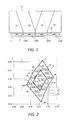
- FIG. 1 is a top plan view of a light source unit for a surface-emitting device in accordance with one embodiment
- FIG. 2 is a chromaticity diagram illustrating ranking of LEDs in a chromaticity range of a chromaticity coordinate system
- FIG. 3 is a diagram illustrating ranking of luminous flux ranges by luminous flux value
- FIG. 4 is a diagram illustrating types of chromaticity regions and luminous flux ranges of the LEDs allocated to each channel of the light source unit of the surface-emitting device.
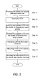
- FIG. 5 is a flowchart illustrating a method for making the light source unit in accordance with one embodiment.
- FIG. 1 is a top plan view of a light source unit 1 for a surface-emitting device.
- the surface-emitting device includes a light source unit 1 and a light guide plate 3.
- the light source unit 1 includes a strip-shaped bar (e.g., LED mount bar) 2 and LEDs (Light Emitting Diodes) that are mounted so as to be aligned in the bar 2.
- the LEDs are mounted on the bar 2 such that the LEDs are disposed facing a light entrance surface 31 of the light guide plate 3.
- the surface-emitting device With this surface-emitting device, light exiting the LEDs is introduced to the light guide plate 3 through the light entrance surface 31, and is surface-emitted by a surface of the light guide plate 3 by the operation of the light guide plate 3 and an optical sheet (not shown) or the like.
- the surface-emitting device emits light from the surface (an upper surface that intersects with the light entrance surface 31) of the light guide plate 3 as an edge light type backlight device for a liquid crystal display.
- the surface-emitting device can be used as a direct light type backlight device when a plurality of the bars 2 is aligned as a plane to emit light from a surface that is opposite the light entrance surface 31.
- the LEDs included in the light source unit 1 are sorted into and allocated to individual channels which are aligned in a plurality of locations in a longitudinal direction of the bar 2. Specifically, four channels indicated as ch1, ch2, ch3, ch4 are partitioned and formed in four locations in the longitudinal direction of the bar 2. A required number of LEDs are assigned positions and arranged for each of the channels ch1 through ch4.
- the specifications of the LEDs e.g., first LEDs, third LEDs
- the specifications of the LEDs e.g., first LEDs, third LEDs
- the channels ch2, ch3 e.g., inside channel and second inside channel
- the center e.g., center portion
- the basic concept of the surface-emitting device is that LEDs having a high chromaticity specification and luminous flux specification (e.g., the subset of LEDs being ranked in a predetermined chromaticity region and ranked in a predetermined luminous flux range) are arranged in the channels ch2, ch3, and LEDs (e.g., second LEDs) arbitrarily selected from among a supplied large number of LEDs (e.g., set of LEDs) are arranged in the channels ch1, ch4 (e.g., outside channels) on both sides.
- the reference symbols Y2 and Y3 refer to the light exiting from the LEDs included in the channels ch2, ch3, and Y1 and Y4 refer to the light exiting from the LEDs included in the channels ch1, ch4.
- the LEDs allocated to the channels ch1 through ch4 in four locations are selected from among the supplied large number of LEDs that are ranked into a plurality of chromaticity regions within a chromaticity range (e.g., predetermined chromaticity range) S (see FIG. 2 ) in a chromaticity coordinate system, and ranked into a plurality of luminous flux ranges according to the luminous flux value thereof.
- the supplied large number of LEDs ranked into the chromaticity regions or the luminous flux ranges herein are a group of LEDs (e.g., a set of LEDs) supplied to manufacturing steps in the manufacturing of the surface-emitting device.
- FIG. 2 is a chromaticity diagram illustrating the ranking of the supplied large number of LEDs in the chromaticity range S in the chromaticity coordinate system.
- FIG. 3 is a diagram illustrating the ranking of the supplied large number of LEDs into the luminous flux ranges.
- the chromaticity diagram illustrated FIG. 2 is a diagram in which color information of the supplied LEDs is mapped on a two dimensional diagram referred to as the CIE 1931 chromaticity diagram. Coordinates are used to bound or define regions (e.g., chromaticity regions) in terms of where the LEDs should be positioned on the CIE 1931 chromaticity diagram.
- the LEDs are supplied by an LED manufacturer based on the LED manufacturer's tables of bounding coordinates for the regions they have defined.
- the LEDs are supplied by an LED manufacture when a user specifies the chromaticity range S based on the coordinates of the CIE 1931 chromaticity diagram or the LED manufacture's code indicating the chromaticity range S.
- FIG. 2 illustrates an example of the chromaticity range S.
- the values of the coordinates of FIG. 2 specifying the chromaticity range S can be different values when the user orders different LEDs having different specification.
- Ranking is applied to the LEDs by using the chromaticity coordinates of the chromaticity diagram (e.g., xy chromaticity diagram in the CIE color system of FIG. 2 ) from the International Commission on Illumination.
- the LED manufacture or the user ranks the LEDs to the chromaticity regions.
- the supplied large number of LEDs is finely ranked into sixteen types of chromaticity regions having four lines and four rows within the chromaticity range S in the chromaticity coordinate system.
- the sixteen types of chromaticity regions are ranked in the following manner. Specifically, the supplied large number of LEDs is ranked into sixteen types of chromaticity regions inside the chromaticity range S which has a substantially rectangular border line L in the chromaticity coordinate system. Reference symbols are paired with the sixteen type of chromaticity regions in a "parent number-daughter number" format as shown below:
- the ranks 1-1, 1-2, 1-3, 1-4 having the parent number "1" are positioned closer to one corner k1 in the chromaticity range S surrounded by the substantially rectangular border line L.
- the ranks 2-1, 2-2, 2-3, 2-4 having the parent number "2" are positioned closer to another corner k2 in the chromaticity range S surrounded by the substantially rectangular border line L.
- the ranks 3-1, 3-2, 3-3, 3-4 having the parent number "3" are positioned closer to another corner k4 in the chromaticity range S surrounded by the substantially rectangular border line L.
- the ranks 4-1, 4-2, 4-3, 4-4 having the parent number "4" are positioned closer to another corner k3 in the chromaticity range S surrounded by the substantially rectangular border line L.
- the range of chromaticity regions belonging to the three ranks 4-1, 4-3, 4-4 therein border on the mutually adjacent two edges h3, h4 of the border line L.
- all of the chromaticity regions included in the chromaticity range S are ranked into two levels which include a first chromaticity region group (e.g., first chromaticity region) A positioned at the center in the chromaticity coordinate system, and a second chromaticity region group (e.g., second chromaticity region) B positioned so as to surround the first chromaticity region group A.
- first chromaticity region group e.g., first chromaticity region
- second chromaticity region group e.g., second chromaticity region
- four types of chromaticity regions that include the ranks 1-3, 2-4, 3-1, and 4-2 are included in the first chromaticity region group A.
- the LEDs included in the first chromaticity region group A are LEDs having a high chromaticity specification that are distributed adjacent to each other at the center of the chromaticity range S.
- the twelve types of chromaticity regions which include the ranks 1-1, 1-2, 1-4, 2-1, 2-2, 2-3, 3-2, 3-3, 3-4, 4-1, 4-3, and 4-4 are included in the second chromaticity region group B.
- the LEDs included in the second chromaticity region group B have a lower specification than the first chromaticity region group A and are distributed adjacent to each other in positions surrounding the periphery of the first chromaticity region group A. In other words, the second chromaticity region group B is located farther from the ideal values of coordinates than the first chromaticity region group A.
- FIG. 3 illustrates the ranking of the luminous flux ranges of the supplied large number of LEDs.
- the supplied large number of LEDs is finely ranked into six types of luminous flux ranges by the reference symbols 22, 23, 24, 25, 26, and 27, as illustrated in the "Bin Rank (old)" column in FIG. 3 .
- the luminous flux (1m) of the LEDs ranked as the luminous flux range of reference symbol 22 is 22 to 23
- the luminous flux (1m) of the LEDs ranked as the luminous flux range of reference symbol 23 is 23 to 24
- the luminous flux (1m) of the LEDs ranked as the luminous flux range of reference symbol 24 is 24 to 25
- the luminous flux (1m) of the LEDs ranked as the luminous flux range of reference symbol 25 is 25 to 26
- the six types of luminous flux ranges 22 through 27 are ranked into two levels which include a first luminous flux range group (e.g., first luminous flux range) a having large luminous flux values, and a second luminous flux range group (e.g., second luminous flux range) b having smaller luminous flux values than the first luminous flux range group a, as shown in the "Bin Rank (new)" column of FIG. 3 .
- first luminous flux range group e.g., first luminous flux range
- second luminous flux range group e.g., second luminous flux range
- four types of luminous flux ranges 24 through 27 are included in the rank of the first luminous flux range group a.
- the LEDs included in the first luminous flux range group a are the LEDs having a high luminous flux specification that are included in the luminous flux ranges 24 through 28.
- Two types of luminous flux ranges 22 and 23 are included in the rank of the second luminous flux range group b.
- the LEDs included in the second luminous flux range group b are the LEDs included in the luminous flux ranges 22 and 23, and have low specifications in relation to the LEDs that are included in the first luminous flux range group a.
- the required number of LEDs are sorted and arranged among the four channels ch1, ch2, ch3, ch4 which are partitioned and formed in four locations in the longitudinal direction of the bar 2 of the light source unit 1, in accordance with the basic concept described with reference to FIG. 1 .
- the required number of LEDs arbitrarily selected from the first chromaticity region group A and the first luminous flux range group a are allocated to the inside channels ch2, ch3 in two locations at the center in the longitudinal direction of the bar 2.
- LEDs arbitrarily selected from the entire range of the first and second chromaticity region groups A, B and the first and second luminous flux range groups a, b are allocated to the outside channels ch1, ch4 in two locations positioned on both sides of the inside channels ch2, ch3.
- the outside channels are located at outside portions of the bar 2.
- the outside portions are disposed longitudinal outside of the bar 2 relative to the center of the bar 2, respectively.
- FIG. 4 illustrates the types of chromaticity region groups according to the chromaticity (CIE), and the types of luminous flux range groups according to the luminous flux (1m) of the LEDs that are sorted for each channel.
- CIE chromaticity
- FIG. 4 illustrates the types of chromaticity region groups according to the chromaticity (CIE), and the types of luminous flux range groups according to the luminous flux (1m) of the LEDs that are sorted for each channel.
- LEDs arbitrarily selected from the first chromaticity region group A are allocated to the inside channels ch2, ch3 of the bar 2
- LEDs arbitrarily selected from the entire range of the first and second chromaticity region groups A, B are allocated to the outside channels ch1, ch4
- all of the LEDs included in the inside channels ch2, ch3 belong to the first luminous flux range group a having a large luminous flux value
- the LEDs included in the outside channels ch1, ch4 are arbitrarily selected from the entire range
- LEDs are sorted into and allocated to the individual channels aligned at four locations in the longitudinal direction of the bar 2 of the light source unit 1. Therefore, there is no need to separately determine the arrangement positions of individual LEDs in the bar 2, and the arrangement position of each ranked LED can be determined for each channel. The work required to arrange the LEDs is therefore reduced, and a step for arranging the LEDs can be omitted.
- the number of combinations is also reduced from 672 for combinations of chromaticity regions, luminous flux ranges, and forward voltages to two, for the first and second groups. Consequently, it is sufficient merely to allocate the LEDs obtained by the single combination A-a of the first chromaticity region group A and the first luminous flux range group a to the inside channels ch2, ch3, as shown in FIG. 4 . It is also sufficient merely to allocate the LEDs obtained by the four combinations A- a , A- b , B- a , and B- b of the first and second chromaticity region groups A, B and the first and second luminous flux range groups a, b to the outside channels ch1, ch4. Consequently, the operations of combining and arranging LEDs in assigned positions in each channel of the bar 2 are simplified.
- the bar 2 is divided into four channels ch1, ch2, ch3, ch4, but the bar 2 can also be divided into three channels, or into five or more channels.
- the one center channel corresponds to the inside channel
- the two channels on both sides thereof correspond to the outside channels.
- the center three channels correspond to the inside channels
- the two channels on both sides thereof correspond to the outside channels.
- a large number of LEDs are ranked into the chromaticity regions within the chromaticity range S in the chromaticity coordinate system, and are ranked into the luminous flux ranges according to the luminous flux value thereof.
- the required number of LEDs are selected from among the large number of LEDs are mounted on the light source unit 1 so as to be aligned in the strip-shaped bar 2.
- Individual channels ch1, ch2, ch3, ch4 are included, to which the required number of LEDs are sorted and allocated.
- the channels ch1, ch2, ch3, ch4 are aligned in a plurality of locations in the longitudinal direction of the bar 2.
- the channels ch1, ch2, ch3, ch4 are partitioned into the inside channels ch2, ch3 positioned at the center in the alignment direction of the channels in a plurality of locations, and the outside channels ch1, ch4 positioned on both sides of the inside channels ch2, ch3.
- the LEDs having a high chromaticity specification and luminous flux specification selected from all of the chromaticity regions and luminous flux ranges are allocated to the inside channels ch2, ch3.
- the chromaticity specification and luminous flux specification of the LEDs allocated to the inside channels ch2, ch3 of the bar 2 of the light source unit 1 are high, and the specifications of the LEDs allocated to the inside channel ch2, ch3 affect the overall specifications of the surface-emitting device as a module.
- the chromaticity specification and luminous flux specification required in the surface-emitting device are satisfied. In other words, allocating LEDs that are arbitrarily selected from all of the plurality of chromaticity regions and the plurality of luminous flux ranges to the outside channels ch1, ch4 does not cause the surface-emitting device to be out of specification.
- the LEDs arbitrarily selected from all of the chromaticity regions and luminous flux ranges are allocated to the outside channels ch1, ch4.
- the LEDs having a high chromaticity specification and luminous flux specification selected from all of the chromaticity regions and luminous flux ranges are allocated to the inside channels ch2, ch3, and the LEDs arbitrarily selected from all of the chromaticity regions and luminous flux ranges (i.e., a mixture of LEDs having high chromaticity and luminous flux specifications and LEDs having low chromaticity and luminous flux specifications) are allocated to the outside channels ch1, ch4. All of the supplied large number of LEDs can therefore be used, and wasting of LEDs is suppressed.
- the LEDs arbitrarily selected from the first chromaticity region group A are allocated to the inside channels ch2, ch3, the first chromaticity region group A is obtained by ranking all of the chromaticity regions into two levels which include the first chromaticity region group A positioned at the center in the chromaticity coordinate system, and the second chromaticity region group B positioned so as to surround the first chromaticity region group A.
- all of the LEDs included in the inside channels ch2, ch3 belong to the first luminous flux range group a obtained by ranking the plurality of luminous flux ranges into two levels which include the first luminous flux range group a having large luminous flux values, and the second luminous flux range group b having smaller luminous flux values than the first luminous flux range group a.
- the chromaticity regions are ranked into two levels which include a first chromaticity region group and a second chromaticity region group, and segmentation of LED specifications is prevented.
- the luminous flux ranges are also ranked into two levels which include a first luminous flux range group and a second luminous flux range group, and segmentation of LED specifications is prevented.
- the LEDs for arrangement in assigned positions in the bar need only be selected from first or second chromaticity region group and the first or second luminous flux range group ranked into two levels, and assignment of positions is facilitated.
- the LEDs allocated to the inside channels ch 2, ch3 of the bar 2 of the light source unit 1 satisfy the chromaticity specification and luminous flux specification required in the surface-emitting device.
- the specifications of the LEDs allocated to the inside channels ch2, ch3 affect the overall specifications of the surface-emitting device as a module.
- the LEDs do not cause the surface-emitting device to be out of specification. Since the LEDs arbitrarily selected from all of the chromaticity regions and luminous flux ranges are also allocated to the outside channels ch1, ch4, all of the supplied large number of LEDs can be used, and wasting of LEDs is suppressed.
- the LEDs arbitrarily selected from the entire range of the first and second chromaticity region groups A, B are allocated to the outside channels ch1, ch4, and the LEDs included in the outside channels ch1, ch4 are arbitrarily selected form the entire range of the first and second luminous flux range groups a, b.
- the LEDs arbitrarily selected from all of the plurality of chromaticity regions and plurality of luminous flux ranges are allocated to the outside channels ch1, ch4, all of the supplied large number of LEDs can be used, and wasting of LEDs is suppressed.
- the required number of LEDs included in the light source unit 1 are sorted and allocated to four channels ch1, ch2, ch3, ch4 aligned in the longitudinal direction of the bar2.
- the two channels at the center of the four channels are designated as the inside channels ch2, ch3, and the two channels positioned on both sides of the two channels are designated as the outside channels ch1, ch4.
- the surface-emitting device can be manufactured by the following steps:
- a surface-emitting device can be provided in which all of the supplied large number of LEDs can be used, and conditions in which chromaticity or luminous flux is out of specification are eliminated in a case in which a large number of LEDs are supplied which have variations due to individual differences in chromaticity range, luminous flux, or other characteristics. Consequently, wasting of LEDs among the supplied LEDs is suppressed, and cost can be reduced. Cost can also be reduced by obviating the need for the complicated work of selecting LEDs having the desired specifications from among the large number of LEDs having segmented specifications.
- the LEDs for the inside channels ch2, ch3 are selected only from the subset of the supplied LEDs that is ranked in the first chromaticity region group A and ranked in the first luminous flux range group a
- the LEDs for the outside channels ch1, ch4 are selected from a combination of the entire range of the first and second chromaticity region groups A, B and the entire range of the first and second luminous flux range groups a, b.
- the LEDs for the outside channels ch1, ch4 are selected from a combination of the subset of the supplied LEDs and outside of the subset of the supplied LEDs.
- the LEDs for the outside channels ch1, ch4 can be selected only from outside of the subset of the supplied LEDs.
- the LEDs for the outside channels ch1, ch4 can be selected only from another subset (or outside of the subset) of the supplied LEDs that is ranked in the second chromaticity region group B and ranked in the second luminous flux range group b.
Landscapes
- Engineering & Computer Science (AREA)
- Physics & Mathematics (AREA)
- Microelectronics & Electronic Packaging (AREA)
- Optics & Photonics (AREA)
- General Engineering & Computer Science (AREA)
- Led Device Packages (AREA)
- Planar Illumination Modules (AREA)
- Led Devices (AREA)
Applications Claiming Priority (2)
| Application Number | Priority Date | Filing Date | Title |
|---|---|---|---|
| JP2010106464 | 2010-05-06 | ||
| JP2011056120A JP2011254064A (ja) | 2010-05-06 | 2011-03-15 | 面発光装置 |
Publications (3)
| Publication Number | Publication Date |
|---|---|
| EP2385293A2 true EP2385293A2 (fr) | 2011-11-09 |
| EP2385293A3 EP2385293A3 (fr) | 2012-07-04 |
| EP2385293B1 EP2385293B1 (fr) | 2014-08-13 |
Family
ID=44545361
Family Applications (1)
| Application Number | Title | Priority Date | Filing Date |
|---|---|---|---|
| EP11164691.5A Not-in-force EP2385293B1 (fr) | 2010-05-06 | 2011-05-04 | Unité de source lumineuse |
Country Status (3)
| Country | Link |
|---|---|
| US (1) | US8608338B2 (fr) |
| EP (1) | EP2385293B1 (fr) |
| JP (1) | JP2011254064A (fr) |
Families Citing this family (7)
| Publication number | Priority date | Publication date | Assignee | Title |
|---|---|---|---|---|
| JP5963524B2 (ja) * | 2012-04-27 | 2016-08-03 | 三菱電機株式会社 | Led選択装置、led選択プログラム及びled選択方法 |
| CN115053357A (zh) * | 2020-03-03 | 2022-09-13 | 株式会社富士 | 发光单元的制造方法 |
| CN113056060B (zh) * | 2020-09-30 | 2022-04-12 | 惠州华阳通用电子有限公司 | 一种led色度调节方法及装置 |
| US12012222B2 (en) * | 2022-05-12 | 2024-06-18 | Panasonic Avionics Corporation | Programmable lighting methods and systems for a removable peripheral bar |
| US11607957B1 (en) | 2022-05-12 | 2023-03-21 | Panasonic Avionics Corporation | Accent lighting based display systems and associated methods thereof |
| USD1066291S1 (en) | 2022-05-12 | 2025-03-11 | Panasonic Avionics Corporation | Display system |
| US12208899B2 (en) | 2022-05-12 | 2025-01-28 | Panasonic Avionics Corporation | Display systems with a modular peripheral bar assembly and associated methods thereof |
Citations (5)
| Publication number | Priority date | Publication date | Assignee | Title |
|---|---|---|---|---|
| JP2001222242A (ja) | 2000-02-10 | 2001-08-17 | Matsushita Electric Ind Co Ltd | 発光ダイオードを用いたディスプレイ |
| JP2008147563A (ja) | 2006-12-13 | 2008-06-26 | Sharp Corp | ばらつきのあるledによる均一バックライトの製造方法 |
| JP2009158903A (ja) | 2007-12-05 | 2009-07-16 | Toshiba Lighting & Technology Corp | Led発光ユニット及び発光装置 |
| JP2010106464A (ja) | 2008-10-28 | 2010-05-13 | Sumitomo Heavy Ind Ltd | ハイブリッド型建設機械 |
| JP2011056120A (ja) | 2009-09-11 | 2011-03-24 | Otsuka Pharmaceut Factory Inc | 医療用複室容器及びその使用方法 |
Family Cites Families (17)
| Publication number | Priority date | Publication date | Assignee | Title |
|---|---|---|---|---|
| US6224240B1 (en) * | 1996-09-13 | 2001-05-01 | Matsushita Electric Industrial Co., Ltd. | Light source |
| JP2002109936A (ja) * | 2000-09-28 | 2002-04-12 | Sanyo Electric Co Ltd | 面光源装置および表示装置 |
| US7212359B2 (en) * | 2003-07-25 | 2007-05-01 | Texas Instruments Incorporated | Color rendering of illumination light in display systems |
| US7066623B2 (en) * | 2003-12-19 | 2006-06-27 | Soo Ghee Lee | Method and apparatus for producing untainted white light using off-white light emitting diodes |
| EP1790199B1 (fr) * | 2004-06-29 | 2013-08-14 | Panasonic Corporation | Source d"éclairage |
| JP4848654B2 (ja) * | 2005-03-25 | 2011-12-28 | 船井電機株式会社 | 液晶表示装置 |
| WO2007060594A2 (fr) * | 2005-11-22 | 2007-05-31 | Koninklijke Philips Electronics N.V. | Système d’éclairage comportant de multiples ensembles de sources de lumière |
| US7309152B2 (en) * | 2005-11-23 | 2007-12-18 | Unity Opto Technology Co., Ltd. | Light source structure of backlight module |
| US7821194B2 (en) * | 2006-04-18 | 2010-10-26 | Cree, Inc. | Solid state lighting devices including light mixtures |
| US8998444B2 (en) * | 2006-04-18 | 2015-04-07 | Cree, Inc. | Solid state lighting devices including light mixtures |
| US8360601B2 (en) | 2007-03-09 | 2013-01-29 | Osram Opto Semiconductors Gmbh | LED module |
| US7703943B2 (en) * | 2007-05-07 | 2010-04-27 | Intematix Corporation | Color tunable light source |
| TWI368794B (en) * | 2008-05-21 | 2012-07-21 | Au Optronics Corp | Illuminant system using high color temperature light emitting diode and manufacture method thereof |
| EP2304309B1 (fr) | 2008-06-25 | 2015-09-30 | Cree, Inc. | Appareils d'éclairage à semi-conducteurs comprenant des mélanges de lumière |
| KR101269592B1 (ko) * | 2008-07-09 | 2013-06-05 | 엘지디스플레이 주식회사 | 액정표시모듈의 엘이디 백라이트 구성방법 |
| US8333631B2 (en) * | 2009-02-19 | 2012-12-18 | Cree, Inc. | Methods for combining light emitting devices in a package and packages including combined light emitting devices |
| TWI383345B (zh) * | 2009-05-22 | 2013-01-21 | Chunghwa Picture Tubes Ltd | 顯示器與其所使用的光源裝置 |
-
2011
- 2011-03-15 JP JP2011056120A patent/JP2011254064A/ja active Pending
- 2011-04-27 US US13/094,958 patent/US8608338B2/en not_active Expired - Fee Related
- 2011-05-04 EP EP11164691.5A patent/EP2385293B1/fr not_active Not-in-force
Patent Citations (5)
| Publication number | Priority date | Publication date | Assignee | Title |
|---|---|---|---|---|
| JP2001222242A (ja) | 2000-02-10 | 2001-08-17 | Matsushita Electric Ind Co Ltd | 発光ダイオードを用いたディスプレイ |
| JP2008147563A (ja) | 2006-12-13 | 2008-06-26 | Sharp Corp | ばらつきのあるledによる均一バックライトの製造方法 |
| JP2009158903A (ja) | 2007-12-05 | 2009-07-16 | Toshiba Lighting & Technology Corp | Led発光ユニット及び発光装置 |
| JP2010106464A (ja) | 2008-10-28 | 2010-05-13 | Sumitomo Heavy Ind Ltd | ハイブリッド型建設機械 |
| JP2011056120A (ja) | 2009-09-11 | 2011-03-24 | Otsuka Pharmaceut Factory Inc | 医療用複室容器及びその使用方法 |
Also Published As
| Publication number | Publication date |
|---|---|
| US8608338B2 (en) | 2013-12-17 |
| US20110273873A1 (en) | 2011-11-10 |
| JP2011254064A (ja) | 2011-12-15 |
| EP2385293A3 (fr) | 2012-07-04 |
| EP2385293B1 (fr) | 2014-08-13 |
Similar Documents
| Publication | Publication Date | Title |
|---|---|---|
| EP2385293B1 (fr) | Unité de source lumineuse | |
| US20100059767A1 (en) | Surface Light-Emitting Device and Display Device Using the Same | |
| JP5302407B2 (ja) | 照明装置および表示装置 | |
| US11143915B2 (en) | Lighting device including light guide plate and display device including the lighting device | |
| JP4430088B2 (ja) | 面光源装置及びこれを備えるバックライトユニット | |
| US8786804B2 (en) | Surface light source device and LCD unit | |
| US20150261042A1 (en) | Surface light-emitting device and liquid crystal display apparatus | |
| CN102418881A (zh) | 背光装置以及液晶显示装置 | |
| US8780297B2 (en) | Backlight module | |
| KR101441984B1 (ko) | 광원 모듈, 이를 갖는 광원 어셈블리 및 표시장치 | |
| US8888351B2 (en) | Backlight assembly and display apparatus including the same | |
| CN101936487B (zh) | 背光模组 | |
| EP2469594A2 (fr) | Module électroluminescent et son procédé de fabrication | |
| US20120057102A1 (en) | Backlight module | |
| TWI757935B (zh) | 背光模組及其發光二極體的佈局方法 | |
| JP5344809B2 (ja) | バックライト装置 | |
| US8610843B2 (en) | Backlight module and liquid crystal display apparatus | |
| JP2012227397A (ja) | 光源の製造方法、および光源 | |
| KR20140117054A (ko) | 백라이트 유닛 및 이를 포함하는 액정표시장치 | |
| CN103062668A (zh) | 背光模组灯条及基于背光模组灯条的led排布方法 | |
| JP4332565B2 (ja) | 三原色発光ダイオードがマトリクス配置された装置 | |
| CN101981367B (zh) | 面光源和包括该面光源的显示装置 | |
| JP2011238368A (ja) | 面発光装置及び面発光装置の製造方法 | |
| US9310034B2 (en) | Light emitting device for backlight device and method of operating the light emitting device | |
| KR102486326B1 (ko) | 백라이트 유닛 및 이를 포함하는 표시장치 |
Legal Events
| Date | Code | Title | Description |
|---|---|---|---|
| AK | Designated contracting states |
Kind code of ref document: A2 Designated state(s): AL AT BE BG CH CY CZ DE DK EE ES FI FR GB GR HR HU IE IS IT LI LT LU LV MC MK MT NL NO PL PT RO RS SE SI SK SM TR |
|
| AX | Request for extension of the european patent |
Extension state: BA ME |
|
| PUAI | Public reference made under article 153(3) epc to a published international application that has entered the european phase |
Free format text: ORIGINAL CODE: 0009012 |
|
| PUAL | Search report despatched |
Free format text: ORIGINAL CODE: 0009013 |
|
| AK | Designated contracting states |
Kind code of ref document: A3 Designated state(s): AL AT BE BG CH CY CZ DE DK EE ES FI FR GB GR HR HU IE IS IT LI LT LU LV MC MK MT NL NO PL PT RO RS SE SI SK SM TR |
|
| AX | Request for extension of the european patent |
Extension state: BA ME |
|
| RIC1 | Information provided on ipc code assigned before grant |
Ipc: H05B 33/08 20060101ALI20120525BHEP Ipc: F21Y 103/00 20060101ALN20120525BHEP Ipc: F21K 99/00 20100101AFI20120525BHEP Ipc: G09G 3/34 20060101ALI20120525BHEP |
|
| 17P | Request for examination filed |
Effective date: 20130102 |
|
| GRAP | Despatch of communication of intention to grant a patent |
Free format text: ORIGINAL CODE: EPIDOSNIGR1 |
|
| INTG | Intention to grant announced |
Effective date: 20140220 |
|
| GRAS | Grant fee paid |
Free format text: ORIGINAL CODE: EPIDOSNIGR3 |
|
| GRAA | (expected) grant |
Free format text: ORIGINAL CODE: 0009210 |
|
| AK | Designated contracting states |
Kind code of ref document: B1 Designated state(s): AL AT BE BG CH CY CZ DE DK EE ES FI FR GB GR HR HU IE IS IT LI LT LU LV MC MK MT NL NO PL PT RO RS SE SI SK SM TR |
|
| REG | Reference to a national code |
Ref country code: GB Ref legal event code: FG4D |
|
| REG | Reference to a national code |
Ref country code: CH Ref legal event code: EP Ref country code: AT Ref legal event code: REF Ref document number: 682468 Country of ref document: AT Kind code of ref document: T Effective date: 20140815 |
|
| REG | Reference to a national code |
Ref country code: IE Ref legal event code: FG4D |
|
| REG | Reference to a national code |
Ref country code: DE Ref legal event code: R096 Ref document number: 602011008998 Country of ref document: DE Effective date: 20140925 |
|
| REG | Reference to a national code |
Ref country code: NL Ref legal event code: VDEP Effective date: 20140813 |
|
| REG | Reference to a national code |
Ref country code: AT Ref legal event code: MK05 Ref document number: 682468 Country of ref document: AT Kind code of ref document: T Effective date: 20140813 |
|
| REG | Reference to a national code |
Ref country code: LT Ref legal event code: MG4D |
|
| PG25 | Lapsed in a contracting state [announced via postgrant information from national office to epo] |
Ref country code: SE Free format text: LAPSE BECAUSE OF FAILURE TO SUBMIT A TRANSLATION OF THE DESCRIPTION OR TO PAY THE FEE WITHIN THE PRESCRIBED TIME-LIMIT Effective date: 20140813 Ref country code: GR Free format text: LAPSE BECAUSE OF FAILURE TO SUBMIT A TRANSLATION OF THE DESCRIPTION OR TO PAY THE FEE WITHIN THE PRESCRIBED TIME-LIMIT Effective date: 20141114 Ref country code: PT Free format text: LAPSE BECAUSE OF FAILURE TO SUBMIT A TRANSLATION OF THE DESCRIPTION OR TO PAY THE FEE WITHIN THE PRESCRIBED TIME-LIMIT Effective date: 20141215 Ref country code: NO Free format text: LAPSE BECAUSE OF FAILURE TO SUBMIT A TRANSLATION OF THE DESCRIPTION OR TO PAY THE FEE WITHIN THE PRESCRIBED TIME-LIMIT Effective date: 20141113 Ref country code: LT Free format text: LAPSE BECAUSE OF FAILURE TO SUBMIT A TRANSLATION OF THE DESCRIPTION OR TO PAY THE FEE WITHIN THE PRESCRIBED TIME-LIMIT Effective date: 20140813 Ref country code: ES Free format text: LAPSE BECAUSE OF FAILURE TO SUBMIT A TRANSLATION OF THE DESCRIPTION OR TO PAY THE FEE WITHIN THE PRESCRIBED TIME-LIMIT Effective date: 20140813 Ref country code: BG Free format text: LAPSE BECAUSE OF FAILURE TO SUBMIT A TRANSLATION OF THE DESCRIPTION OR TO PAY THE FEE WITHIN THE PRESCRIBED TIME-LIMIT Effective date: 20141113 Ref country code: FI Free format text: LAPSE BECAUSE OF FAILURE TO SUBMIT A TRANSLATION OF THE DESCRIPTION OR TO PAY THE FEE WITHIN THE PRESCRIBED TIME-LIMIT Effective date: 20140813 |
|
| PG25 | Lapsed in a contracting state [announced via postgrant information from national office to epo] |
Ref country code: AT Free format text: LAPSE BECAUSE OF FAILURE TO SUBMIT A TRANSLATION OF THE DESCRIPTION OR TO PAY THE FEE WITHIN THE PRESCRIBED TIME-LIMIT Effective date: 20140813 Ref country code: IS Free format text: LAPSE BECAUSE OF FAILURE TO SUBMIT A TRANSLATION OF THE DESCRIPTION OR TO PAY THE FEE WITHIN THE PRESCRIBED TIME-LIMIT Effective date: 20141213 Ref country code: HR Free format text: LAPSE BECAUSE OF FAILURE TO SUBMIT A TRANSLATION OF THE DESCRIPTION OR TO PAY THE FEE WITHIN THE PRESCRIBED TIME-LIMIT Effective date: 20140813 Ref country code: CY Free format text: LAPSE BECAUSE OF FAILURE TO SUBMIT A TRANSLATION OF THE DESCRIPTION OR TO PAY THE FEE WITHIN THE PRESCRIBED TIME-LIMIT Effective date: 20140813 Ref country code: RS Free format text: LAPSE BECAUSE OF FAILURE TO SUBMIT A TRANSLATION OF THE DESCRIPTION OR TO PAY THE FEE WITHIN THE PRESCRIBED TIME-LIMIT Effective date: 20140813 Ref country code: LV Free format text: LAPSE BECAUSE OF FAILURE TO SUBMIT A TRANSLATION OF THE DESCRIPTION OR TO PAY THE FEE WITHIN THE PRESCRIBED TIME-LIMIT Effective date: 20140813 |
|
| PG25 | Lapsed in a contracting state [announced via postgrant information from national office to epo] |
Ref country code: NL Free format text: LAPSE BECAUSE OF FAILURE TO SUBMIT A TRANSLATION OF THE DESCRIPTION OR TO PAY THE FEE WITHIN THE PRESCRIBED TIME-LIMIT Effective date: 20140813 |
|
| PG25 | Lapsed in a contracting state [announced via postgrant information from national office to epo] |
Ref country code: EE Free format text: LAPSE BECAUSE OF FAILURE TO SUBMIT A TRANSLATION OF THE DESCRIPTION OR TO PAY THE FEE WITHIN THE PRESCRIBED TIME-LIMIT Effective date: 20140813 Ref country code: IT Free format text: LAPSE BECAUSE OF FAILURE TO SUBMIT A TRANSLATION OF THE DESCRIPTION OR TO PAY THE FEE WITHIN THE PRESCRIBED TIME-LIMIT Effective date: 20140813 Ref country code: RO Free format text: LAPSE BECAUSE OF FAILURE TO SUBMIT A TRANSLATION OF THE DESCRIPTION OR TO PAY THE FEE WITHIN THE PRESCRIBED TIME-LIMIT Effective date: 20140813 Ref country code: SK Free format text: LAPSE BECAUSE OF FAILURE TO SUBMIT A TRANSLATION OF THE DESCRIPTION OR TO PAY THE FEE WITHIN THE PRESCRIBED TIME-LIMIT Effective date: 20140813 Ref country code: DK Free format text: LAPSE BECAUSE OF FAILURE TO SUBMIT A TRANSLATION OF THE DESCRIPTION OR TO PAY THE FEE WITHIN THE PRESCRIBED TIME-LIMIT Effective date: 20140813 Ref country code: CZ Free format text: LAPSE BECAUSE OF FAILURE TO SUBMIT A TRANSLATION OF THE DESCRIPTION OR TO PAY THE FEE WITHIN THE PRESCRIBED TIME-LIMIT Effective date: 20140813 |
|
| REG | Reference to a national code |
Ref country code: DE Ref legal event code: R097 Ref document number: 602011008998 Country of ref document: DE |
|
| PG25 | Lapsed in a contracting state [announced via postgrant information from national office to epo] |
Ref country code: PL Free format text: LAPSE BECAUSE OF FAILURE TO SUBMIT A TRANSLATION OF THE DESCRIPTION OR TO PAY THE FEE WITHIN THE PRESCRIBED TIME-LIMIT Effective date: 20140813 |
|
| PLBE | No opposition filed within time limit |
Free format text: ORIGINAL CODE: 0009261 |
|
| STAA | Information on the status of an ep patent application or granted ep patent |
Free format text: STATUS: NO OPPOSITION FILED WITHIN TIME LIMIT |
|
| 26N | No opposition filed |
Effective date: 20150515 |
|
| PG25 | Lapsed in a contracting state [announced via postgrant information from national office to epo] |
Ref country code: SI Free format text: LAPSE BECAUSE OF FAILURE TO SUBMIT A TRANSLATION OF THE DESCRIPTION OR TO PAY THE FEE WITHIN THE PRESCRIBED TIME-LIMIT Effective date: 20140813 |
|
| REG | Reference to a national code |
Ref country code: DE Ref legal event code: R119 Ref document number: 602011008998 Country of ref document: DE |
|
| REG | Reference to a national code |
Ref country code: CH Ref legal event code: PL |
|
| GBPC | Gb: european patent ceased through non-payment of renewal fee |
Effective date: 20150504 |
|
| PG25 | Lapsed in a contracting state [announced via postgrant information from national office to epo] |
Ref country code: LI Free format text: LAPSE BECAUSE OF NON-PAYMENT OF DUE FEES Effective date: 20150531 Ref country code: CH Free format text: LAPSE BECAUSE OF NON-PAYMENT OF DUE FEES Effective date: 20150531 Ref country code: LU Free format text: LAPSE BECAUSE OF FAILURE TO SUBMIT A TRANSLATION OF THE DESCRIPTION OR TO PAY THE FEE WITHIN THE PRESCRIBED TIME-LIMIT Effective date: 20150504 Ref country code: MC Free format text: LAPSE BECAUSE OF FAILURE TO SUBMIT A TRANSLATION OF THE DESCRIPTION OR TO PAY THE FEE WITHIN THE PRESCRIBED TIME-LIMIT Effective date: 20140813 |
|
| REG | Reference to a national code |
Ref country code: IE Ref legal event code: MM4A |
|
| REG | Reference to a national code |
Ref country code: FR Ref legal event code: ST Effective date: 20160129 |
|
| PG25 | Lapsed in a contracting state [announced via postgrant information from national office to epo] |
Ref country code: DE Free format text: LAPSE BECAUSE OF NON-PAYMENT OF DUE FEES Effective date: 20151201 Ref country code: IE Free format text: LAPSE BECAUSE OF NON-PAYMENT OF DUE FEES Effective date: 20150504 Ref country code: GB Free format text: LAPSE BECAUSE OF NON-PAYMENT OF DUE FEES Effective date: 20150504 |
|
| PG25 | Lapsed in a contracting state [announced via postgrant information from national office to epo] |
Ref country code: FR Free format text: LAPSE BECAUSE OF NON-PAYMENT OF DUE FEES Effective date: 20150601 |
|
| PG25 | Lapsed in a contracting state [announced via postgrant information from national office to epo] |
Ref country code: BE Free format text: LAPSE BECAUSE OF FAILURE TO SUBMIT A TRANSLATION OF THE DESCRIPTION OR TO PAY THE FEE WITHIN THE PRESCRIBED TIME-LIMIT Effective date: 20140813 |
|
| PG25 | Lapsed in a contracting state [announced via postgrant information from national office to epo] |
Ref country code: MT Free format text: LAPSE BECAUSE OF FAILURE TO SUBMIT A TRANSLATION OF THE DESCRIPTION OR TO PAY THE FEE WITHIN THE PRESCRIBED TIME-LIMIT Effective date: 20140813 |
|
| PG25 | Lapsed in a contracting state [announced via postgrant information from national office to epo] |
Ref country code: HU Free format text: LAPSE BECAUSE OF FAILURE TO SUBMIT A TRANSLATION OF THE DESCRIPTION OR TO PAY THE FEE WITHIN THE PRESCRIBED TIME-LIMIT; INVALID AB INITIO Effective date: 20110504 Ref country code: SM Free format text: LAPSE BECAUSE OF FAILURE TO SUBMIT A TRANSLATION OF THE DESCRIPTION OR TO PAY THE FEE WITHIN THE PRESCRIBED TIME-LIMIT Effective date: 20140813 |
|
| PG25 | Lapsed in a contracting state [announced via postgrant information from national office to epo] |
Ref country code: TR Free format text: LAPSE BECAUSE OF FAILURE TO SUBMIT A TRANSLATION OF THE DESCRIPTION OR TO PAY THE FEE WITHIN THE PRESCRIBED TIME-LIMIT Effective date: 20140813 |
|
| PG25 | Lapsed in a contracting state [announced via postgrant information from national office to epo] |
Ref country code: MK Free format text: LAPSE BECAUSE OF FAILURE TO SUBMIT A TRANSLATION OF THE DESCRIPTION OR TO PAY THE FEE WITHIN THE PRESCRIBED TIME-LIMIT Effective date: 20140813 |
|
| PG25 | Lapsed in a contracting state [announced via postgrant information from national office to epo] |
Ref country code: AL Free format text: LAPSE BECAUSE OF FAILURE TO SUBMIT A TRANSLATION OF THE DESCRIPTION OR TO PAY THE FEE WITHIN THE PRESCRIBED TIME-LIMIT Effective date: 20140813 |