US8610843B2 - Backlight module and liquid crystal display apparatus - Google Patents

Backlight module and liquid crystal display apparatus Download PDF

Info

Publication number
US8610843B2
US8610843B2 US12/996,336 US99633610A US8610843B2 US 8610843 B2 US8610843 B2 US 8610843B2 US 99633610 A US99633610 A US 99633610A US 8610843 B2 US8610843 B2 US 8610843B2
Authority
US
United States
Prior art keywords
light
backlight module
positive voltage
center
voltage bin
Prior art date
Legal status (The legal status is an assumption and is not a legal conclusion. Google has not performed a legal analysis and makes no representation as to the accuracy of the status listed.)
Active, expires
Application number
US12/996,336
Other versions
US20120057103A1 (en
Inventor
Qian Cao
Poying Lin
Yicheng Kuo
Current Assignee (The listed assignees may be inaccurate. Google has not performed a legal analysis and makes no representation or warranty as to the accuracy of the list.)
TCL China Star Optoelectronics Technology Co Ltd
Original Assignee
Shenzhen China Star Optoelectronics Technology Co Ltd
Priority date (The priority date is an assumption and is not a legal conclusion. Google has not performed a legal analysis and makes no representation as to the accuracy of the date listed.)
Filing date
Publication date
Application filed by Shenzhen China Star Optoelectronics Technology Co Ltd filed Critical Shenzhen China Star Optoelectronics Technology Co Ltd
Assigned to SHENZEN CHINA STAR OPTOELECTRONICS TECHNOLOGY CO., LTD. reassignment SHENZEN CHINA STAR OPTOELECTRONICS TECHNOLOGY CO., LTD. ASSIGNMENT OF ASSIGNORS INTEREST (SEE DOCUMENT FOR DETAILS). Assignors: CAO, Qian, KUO, YICHENG, LIN, POYING
Publication of US20120057103A1 publication Critical patent/US20120057103A1/en
Application granted granted Critical
Publication of US8610843B2 publication Critical patent/US8610843B2/en
Active legal-status Critical Current
Adjusted expiration legal-status Critical

Links

Images

Classifications

    • GPHYSICS
    • G02OPTICS
    • G02FOPTICAL DEVICES OR ARRANGEMENTS FOR THE CONTROL OF LIGHT BY MODIFICATION OF THE OPTICAL PROPERTIES OF THE MEDIA OF THE ELEMENTS INVOLVED THEREIN; NON-LINEAR OPTICS; FREQUENCY-CHANGING OF LIGHT; OPTICAL LOGIC ELEMENTS; OPTICAL ANALOGUE/DIGITAL CONVERTERS
    • G02F1/00Devices or arrangements for the control of the intensity, colour, phase, polarisation or direction of light arriving from an independent light source, e.g. switching, gating or modulating; Non-linear optics
    • G02F1/01Devices or arrangements for the control of the intensity, colour, phase, polarisation or direction of light arriving from an independent light source, e.g. switching, gating or modulating; Non-linear optics for the control of the intensity, phase, polarisation or colour 
    • G02F1/13Devices or arrangements for the control of the intensity, colour, phase, polarisation or direction of light arriving from an independent light source, e.g. switching, gating or modulating; Non-linear optics for the control of the intensity, phase, polarisation or colour  based on liquid crystals, e.g. single liquid crystal display cells
    • G02F1/133Constructional arrangements; Operation of liquid crystal cells; Circuit arrangements
    • G02F1/1333Constructional arrangements; Manufacturing methods
    • G02F1/1335Structural association of cells with optical devices, e.g. polarisers or reflectors
    • G02F1/1336Illuminating devices
    • G02F1/133602Direct backlight
    • G02F1/133603Direct backlight with LEDs
    • GPHYSICS
    • G02OPTICS
    • G02FOPTICAL DEVICES OR ARRANGEMENTS FOR THE CONTROL OF LIGHT BY MODIFICATION OF THE OPTICAL PROPERTIES OF THE MEDIA OF THE ELEMENTS INVOLVED THEREIN; NON-LINEAR OPTICS; FREQUENCY-CHANGING OF LIGHT; OPTICAL LOGIC ELEMENTS; OPTICAL ANALOGUE/DIGITAL CONVERTERS
    • G02F1/00Devices or arrangements for the control of the intensity, colour, phase, polarisation or direction of light arriving from an independent light source, e.g. switching, gating or modulating; Non-linear optics
    • G02F1/01Devices or arrangements for the control of the intensity, colour, phase, polarisation or direction of light arriving from an independent light source, e.g. switching, gating or modulating; Non-linear optics for the control of the intensity, phase, polarisation or colour 
    • G02F1/13Devices or arrangements for the control of the intensity, colour, phase, polarisation or direction of light arriving from an independent light source, e.g. switching, gating or modulating; Non-linear optics for the control of the intensity, phase, polarisation or colour  based on liquid crystals, e.g. single liquid crystal display cells
    • G02F1/133Constructional arrangements; Operation of liquid crystal cells; Circuit arrangements
    • G02F1/1333Constructional arrangements; Manufacturing methods
    • G02F1/1335Structural association of cells with optical devices, e.g. polarisers or reflectors
    • G02F1/1336Illuminating devices
    • G02F1/133602Direct backlight
    • G02F1/133611Direct backlight including means for improving the brightness uniformity
    • GPHYSICS
    • G02OPTICS
    • G02FOPTICAL DEVICES OR ARRANGEMENTS FOR THE CONTROL OF LIGHT BY MODIFICATION OF THE OPTICAL PROPERTIES OF THE MEDIA OF THE ELEMENTS INVOLVED THEREIN; NON-LINEAR OPTICS; FREQUENCY-CHANGING OF LIGHT; OPTICAL LOGIC ELEMENTS; OPTICAL ANALOGUE/DIGITAL CONVERTERS
    • G02F1/00Devices or arrangements for the control of the intensity, colour, phase, polarisation or direction of light arriving from an independent light source, e.g. switching, gating or modulating; Non-linear optics
    • G02F1/01Devices or arrangements for the control of the intensity, colour, phase, polarisation or direction of light arriving from an independent light source, e.g. switching, gating or modulating; Non-linear optics for the control of the intensity, phase, polarisation or colour 
    • G02F1/13Devices or arrangements for the control of the intensity, colour, phase, polarisation or direction of light arriving from an independent light source, e.g. switching, gating or modulating; Non-linear optics for the control of the intensity, phase, polarisation or colour  based on liquid crystals, e.g. single liquid crystal display cells
    • G02F1/133Constructional arrangements; Operation of liquid crystal cells; Circuit arrangements
    • G02F1/1333Constructional arrangements; Manufacturing methods
    • G02F1/1335Structural association of cells with optical devices, e.g. polarisers or reflectors
    • G02F1/1336Illuminating devices
    • G02F1/133602Direct backlight
    • G02F1/133613Direct backlight characterized by the sequence of light sources
    • GPHYSICS
    • G02OPTICS
    • G02FOPTICAL DEVICES OR ARRANGEMENTS FOR THE CONTROL OF LIGHT BY MODIFICATION OF THE OPTICAL PROPERTIES OF THE MEDIA OF THE ELEMENTS INVOLVED THEREIN; NON-LINEAR OPTICS; FREQUENCY-CHANGING OF LIGHT; OPTICAL LOGIC ELEMENTS; OPTICAL ANALOGUE/DIGITAL CONVERTERS
    • G02F1/00Devices or arrangements for the control of the intensity, colour, phase, polarisation or direction of light arriving from an independent light source, e.g. switching, gating or modulating; Non-linear optics
    • G02F1/01Devices or arrangements for the control of the intensity, colour, phase, polarisation or direction of light arriving from an independent light source, e.g. switching, gating or modulating; Non-linear optics for the control of the intensity, phase, polarisation or colour 
    • G02F1/13Devices or arrangements for the control of the intensity, colour, phase, polarisation or direction of light arriving from an independent light source, e.g. switching, gating or modulating; Non-linear optics for the control of the intensity, phase, polarisation or colour  based on liquid crystals, e.g. single liquid crystal display cells
    • G02F1/133Constructional arrangements; Operation of liquid crystal cells; Circuit arrangements
    • G02F1/1333Constructional arrangements; Manufacturing methods
    • G02F1/1335Structural association of cells with optical devices, e.g. polarisers or reflectors
    • G02F1/1336Illuminating devices
    • G02F1/133615Edge-illuminating devices, i.e. illuminating from the side

Definitions

  • the present invention generally relates to a backlight module and a liquid crystal display apparatus, and more particularly to a backlight module and a liquid crystal display apparatus capable of promoting LED temperature distribution.
  • a liquid crystal display is mainly manufactured by producing a backlight module composed by a backlight source, a housing and a diffuser plate first, and then assembling the backlight module with a liquid crystal front panel and a frame to compose a LCD module for manufacturing a final product.
  • the backlight module which the backlight sources of the liquid crystal display utilizes Cold Cathode Fluorescent Lamps (CCFL) is now substantially replaced by a LED backlight module because the properties of the low power consumption and mercury free of the LED backlight module. Consequently, the CCFL backlight module will be history ultimately. The LED backlight module will replace overall with no doubt.
  • the LEDs are generally laid out on the light bars in the backlight module utilizing the LEDs as the backlight sources.
  • a predetermined specification will be introduced to select the mass-production LEDs and classify thereof.
  • the indexes of performance employed for classifying the LEDs includes the brightness, the chrominance, the wavelength or the positive voltage bin of the LEDs. Accordingly, the LEDs can be classified by the aforesaid indexes.
  • the display manufacturer generally selects the LEDs belonging to a major bin to be laid out on the light bars.
  • the backlight uniformity of the display apparatus is extremely severe, therefore, the range to select the LEDs for the display manufacturer is essentially narrowed down. Therefore, the ratio of the selected LEDs in the mass-production LEDs is inevitably too small.
  • the present invention provides a backlight module and a liquid crystal display apparatus.
  • the present invention provides a backlight module, employed in a liquid crystal display apparatus having a back plate and a plurality of LEDs (Light Emitting Diode).
  • the liquid crystal display apparatus has a display area in accordance with the back plate and overlaps therewith and the display area has a display area center line (AA area center line).
  • the display area center line has a center corresponding to the LEDs.
  • the LEDs are classified to belong to several positive voltage bins respectively. The LEDs belonging to a lower positive voltage bin are positioned closer to the center and the LEDs belonging to a higher positive voltage bin are positioned farther to the center.
  • the present invention provides a liquid crystal display apparatus comprising a backlight module.
  • the backlight module comprises a back plate positioned at the bottom of the backlight module, the liquid crystal display apparatus has a display area in accordance with the back plate and overlaps therewith, and the display area has a display area center line; and a plurality of LEDs, classified to belong to several positive voltage bins respectively, and the display area center line has a center corresponding to the LEDs, wherein the LEDs belonging to a lower positive voltage bin are positioned closer to the center and the LEDs belonging to a higher positive voltage bin are positioned farther to the center.
  • the LED backlight module and the liquid crystal display apparatus manufactured according to the present invention not only the usage of the LEDs utilized for the liquid crystal display apparatus can be raised, but also the limitation of using one set of LEDs, which belong to the same bin in demand is no longer existing. Meanwhile, the LED temperature distribution in the LED backlight module can be promoted. Accordingly, the non-uniformity issues of brightness and chrominance of the backlight module and the liquid crystal display apparatus can be promoted.
  • FIG. 1 shows a diagram of a LED backlight module according to the first embodiment of the present invention
  • FIG. 2 shows a diagram of a LED backlight module according to the second embodiment of the present invention
  • FIG. 3 shows a diagram of a LED backlight module according to the third embodiment of the present invention.
  • FIG. 4 shows a diagram of a LED backlight module according to the fourth embodiment of the present invention.
  • FIG. 5 shows a diagram of a LED backlight module according to the fifth embodiment of the present invention.
  • FIG. 6 shows a diagram of a LED backlight module according to the sixth embodiment of the present invention.
  • FIG. 7 shows a diagram of a LED backlight module according to the seventh embodiment of the present invention.
  • FIG. 8 shows a diagram of a LED backlight module according to the eighth embodiment of the present invention.
  • FIG. 9 shows an explanation diagram of raising a usage of the LEDs according to the present invention.
  • FIG. 1 shows a diagram of a LED backlight module according to the first embodiment of the present invention.
  • the LED backlight module according to the first embodiment of the present invention is employed in a liquid crystal display apparatus.
  • the backlight module in this embodiment is a side light type LED backlight module.
  • Vf BIN positive voltage bin
  • the positive voltage of the first voltage bin is the highest.
  • the positive voltage of the fourth voltage bin is the lowest.
  • the LEDs 60 belong to the first voltage bin.
  • the LEDs 50 belong to the second voltage bin.
  • the LEDs 40 belong to the third voltage bin.
  • the LEDs belonging to the fourth voltage bin will not be used.
  • the LEDs 40 are arranged in a first light group.
  • the LEDs 50 are arranged in a second light group.
  • the LEDs 60 are arranged in a third light group.
  • the LED backlight module shown in FIG. 1 comprises a back plate 10 , a light guide plate 20 , a light bar 30 and a plurality of LEDs 40 - 60 .
  • the light bar 30 corresponds to the light guide plate 20 and is positioned at a side of the light guide plate 20 perpendicular to the display center line 14 .
  • the plurality of LEDs 40 - 60 is positioned at the light bar 30 and faces the incident surface of the light guide plate 20 .
  • the incident surface of the light guide plate 20 is a plane.
  • the liquid crystal display apparatus comprises a display area 12 in accordance with the back plate 10 and overlaps therewith.
  • the display area 12 has a display area center line 14 (AA area center line).
  • the display area center line 14 has a center 14 - 1 corresponding to the LEDs.
  • the LEDs 40 (the first light group) belonging to the lowest positive voltage bin are positioned closest to the position of the center 14 - 1 .
  • the LEDs 60 (the third light group) belonging to the highest positive voltage bin are positioned farthest to the position of the center 14 - 1 .
  • the LEDs 50 (the second light group) are positioned among the LEDs 40 (the first light group) and the LEDs 60 (the third light group).
  • FIG. 2 shows a diagram of a LED backlight module according to the second embodiment of the present invention.
  • the backlight module in this embodiment is a side light type LED backlight module.
  • Vf BIN positive voltage bin
  • the positive voltage of the first voltage bin is the highest.
  • the positive voltage of the fourth voltage bin is the lowest.
  • the LEDs 60 belong to the first voltage bin.
  • the LEDs 50 belong to the second voltage bin.
  • the LEDs 40 belong to the third voltage bin.
  • the LEDs belonging to the fourth voltage bin will not be used.
  • the LEDs 40 are arranged in a first light group.
  • the LEDs 50 are arranged in a second light group.
  • the LEDs 60 are arranged in a third light group.
  • the LED backlight module comprises a back plate 10 , a light guide plate 20 , a light bar 30 - 1 , a light bar 30 - 2 and a plurality of LEDs 40 - 60 .
  • the liquid crystal display apparatus comprises a display area 12 in accordance with the back plate 10 and overlaps therewith.
  • the display area 12 has a display area center line 14 .
  • the display area center line 14 has a center 14 - 1 corresponding to the LEDs.
  • the light bar 30 - 1 and the light bar 30 - 2 are symmetrically laid out regarding the center 14 - 1 and positioned at a side of the light guide plate 20 perpendicular to the display center line 14 .
  • the plurality of LEDs 40 , 50 and 60 is positioned at the light bar 30 - 1 and the light bar 30 - 2 and faces the incident surface of the light guide plate 20 .
  • the incident surface of the light guide plate 20 is a plane.
  • the LEDs 40 (the first light group) belong the lowest positive voltage bin are positioned at the light bar 30 - 1 and the light bar 30 - 2 closest to the position of the center 14 - 1 .
  • the LEDs 60 (the third light group) belong the highest positive voltage bin are positioned at the light bar 30 - 1 and the light bar 30 - 2 farthest to the position of the center 14 - 1 .
  • FIG. 3 shows a diagram of a LED backlight module according to the third embodiment of the present invention.
  • the backlight module in this embodiment is a side light type LED backlight module.
  • Vf BIN positive voltage bin
  • the positive voltage of the first voltage bin is the highest.
  • the positive voltage of the fourth voltage bin is the lowest.
  • the LEDs 60 belong to the first voltage bin.
  • the LEDs 50 belong to the second voltage bin.
  • the LEDs 40 belong to the third voltage bin.
  • the LEDs belonging to the fourth voltage bin will not be used.
  • the LEDs 40 are arranged in a first light group.
  • the LEDs 50 are arranged in a second light group.
  • the LEDs 60 are arranged in a third light group.
  • the LED backlight module comprises a back plate 10 , a light guide plate 20 , four light bars 30 - 1 , 30 - 2 , 30 - 3 , 30 - 4 and a plurality of LEDs 40 - 60 .
  • the liquid crystal display apparatus comprises a display area 12 in accordance with the back plate 10 and overlaps therewith.
  • the display area 12 has a display area center line 14 .
  • the display area center line 14 has a center 14 - 1 corresponding to the LEDs.
  • the light bars 30 - 1 , 30 - 2 , 30 - 3 , 30 - 4 are symmetrically laid out regarding the center 14 - 1 and positioned at a side of the light guide plate 20 perpendicular to the display center line 14 .
  • the LEDs 40 - 60 correspond to the light guide plate 20 and face the incident surface of the light guide plate 20 .
  • the incident surface of the light guide plate 20 is a plane.
  • the light bars 30 - 2 , 30 - 3 are closet to the center 14 - 1 .
  • the light bars 30 - 1 , 30 - 4 are farthest to the center 14 - 1 .
  • the LEDs 40 (the first light group) are positioned at the light bars 30 - 2 and 30 - 3 closest to the position of the center 14 - 1 .
  • the LEDs 50 (the third light group) are positioned at the light bars 30 - 2 and 30 - 3 farther to the position of the center 14 - 1 .
  • the LEDs 60 (the third light group) are positioned farthest to the position of the center 14 - 1 .
  • FIG. 4 , FIG. 5 and FIG. 6 respectively show LED backlight modules according to the fourth, fifth and sixth embodiments of the present invention.
  • the backlight modules in the fourth, fifth and sixth embodiments are similar to the backlight module in the third embodiment.
  • the difference is that the incident surface of the light guide plate 20 - 1 facing the light bars 30 - 1 , 30 - 2 , 30 - 3 , 30 - 4 has a plurality of concaves.
  • the incident surface of the light guide plate 20 - 2 facing the light bars 30 - 1 , 30 - 2 , 30 - 3 , 30 - 4 has a plurality of convexes in the fifth embodiment.
  • the incident surface of the light guide plate 20 - 3 facing the light bars 30 - 1 , 30 - 2 , 30 - 3 , 30 - 4 is a jagged structure surface in the sixth embodiment.
  • FIG. 7 shows a diagram of a LED backlight module according to the seventh embodiment of the present invention.
  • the backlight module in this embodiment is a direct light type LED backlight module.
  • the LED backlight module comprises a back plate 10 , a plurality of light bars 30 - 5 and a plurality of LEDs.
  • the liquid crystal display apparatus comprises has a display area center line 14 .
  • the display area center line 14 has a center 14 - 1 corresponding to the LEDs around the central position of the back plate 10 .
  • the center 14 - 1 is substantially at the central position of the back plate 10 .
  • Vf BIN positive voltage bin
  • the plurality of LEDs is classified into four bins, the first voltage bin (V 1 ), the second voltage bin (V 2 ), the third voltage bin (V 3 ) and the fourth voltage bin (V 4 ).
  • the positive voltage of the first voltage bin (V 1 ) is the highest.
  • the positive voltage of the fourth voltage bin (V 4 ) is the lowest.
  • the plurality of light bars 30 - 5 is laid out on the back plate 10 . As shown in FIG. 7 , the LEDs belonging to the fourth voltage bin will not be used.
  • the LEDs belonging to the third voltage bin (V 3 ) are positioned on the light bar at the center 14 - 1 .
  • the LEDs belonging to the second voltage bin (V 2 ) are positioned on the light bars at the top, the bottom, the left and the right of the center 14 - 1 .
  • the LEDs belonging to the first voltage bin (V 1 ) are positioned on the light bars at the upper right, the lower right, the upper left and the lower left of the center 14 - 1 .
  • the amount of the light bar 30 - 5 is not specifically limited in this embodiment.
  • FIG. 8 shows a diagram of a LED backlight module according to the eighth embodiment of the present invention.
  • the backlight module in this embodiment is a direct light type LED backlight module.
  • a diagram of that a plurality of LEDs, classified according to positive voltage bin (Vf BIN) is disclosed.
  • the plurality of LEDs is classified into four bins, the first voltage bin (V 1 ), the second voltage bin (V 2 ), the third voltage bin (V 3 ) and the fourth voltage bin (V 4 ).
  • the LED backlight module comprises a back plate 10 and a plurality of LEDs.
  • the LED backlight module does not comprise any light bars but the LEDs are directly laid out on the back plate 10 .
  • the LEDs belonging to the third voltage bin (V 3 ) are positioned around the center 14 - 1 .
  • the LEDs belonging to the second voltage bin (V 2 ) are positioned at the top, the bottom, the left and the right of the center 14 - 1 .
  • the LEDs belonging to the first voltage bin (V 1 ) are positioned at the upper right, the lower right, the upper left and the lower left of the center 14 - 1 .
  • the amount of LED V 1 , V 2 , V 3 , V 4 and their positions on the back plate 10 are not specifically limited in this embodiment.
  • the present invention also provides a liquid crystal display apparatus utilizing any of the LED backlight modules described in the first embodiment ⁇ the eighth embodiment.
  • the LED backlight module of the liquid crystal display apparatus according to the present invention comprises a back plate and a plurality of LEDs.
  • the back plate is positioned at the bottom of the backlight module and is a portion of the backlight module.
  • the liquid crystal display apparatus has a display area in accordance with the back plate and overlaps therewith.
  • the display area has a display area center line.
  • the plurality of LEDs is classified to belong to several positive voltage bins, respectively.
  • the display area center line has a center corresponding to the LEDs.
  • the LEDs belonging to a lower positive voltage bin are positioned closer to the center and the LEDs belonging to a higher positive voltage bin are positioned farther to the center.
  • FIG. 9 shows an explanation diagram of raising an usage of the LEDs according to the present invention.
  • a diagram of that a plurality of LEDs for a backlight module, classified according to positive voltage bin (Vf BIN) in prior art is disclosed.
  • the LEDs belonging to the third voltage bin (V 3 ) are used.
  • the LEDs belonging to the first, second and third voltage bins can be used for the backlight module.
  • the LEDs belonging to a lower positive voltage bin are positioned closer to the center and the LEDs belonging to a higher positive voltage bin are positioned farther to the center. Therefore, the temperature around the center of the backlight module can be reduced to promote the LED temperature distribution. Accordingly, the brightness and chrominance at the center and the brightness and chrominance at periphery can be more uniformly equivalent.

Abstract

The present invention discloses a backlight module and a liquid crystal display apparatus. The backlight module is employed in a liquid crystal display apparatus having a back plate and a plurality of LEDs. The liquid crystal display apparatus has a display area in accordance with the back plate and overlaps therewith, and the display area has a display area center line. The display area center line has a center corresponding to the LEDs. The LEDs are classified to belong to several positive voltage bins respectively. The LEDs belonging to a lower positive voltage bin are positioned closer to the center and the LEDs belonging to a higher positive voltage bin are positioned farther to the center.

Description

BACKGROUND OF THE INVENTION
1. Field of the Invention
The present invention generally relates to a backlight module and a liquid crystal display apparatus, and more particularly to a backlight module and a liquid crystal display apparatus capable of promoting LED temperature distribution.
2. Description of Prior Art
Nowadays, a liquid crystal display (LCD) is mainly manufactured by producing a backlight module composed by a backlight source, a housing and a diffuser plate first, and then assembling the backlight module with a liquid crystal front panel and a frame to compose a LCD module for manufacturing a final product. Generally, the backlight module which the backlight sources of the liquid crystal display utilizes Cold Cathode Fluorescent Lamps (CCFL) is now substantially replaced by a LED backlight module because the properties of the low power consumption and mercury free of the LED backlight module. Consequently, the CCFL backlight module will be history ultimately. The LED backlight module will replace overall with no doubt.
Now, the LEDs are generally laid out on the light bars in the backlight module utilizing the LEDs as the backlight sources. A predetermined specification will be introduced to select the mass-production LEDs and classify thereof. Generally, the indexes of performance employed for classifying the LEDs includes the brightness, the chrominance, the wavelength or the positive voltage bin of the LEDs. Accordingly, the LEDs can be classified by the aforesaid indexes. The display manufacturer generally selects the LEDs belonging to a major bin to be laid out on the light bars. On the other hand, the backlight uniformity of the display apparatus is extremely severe, therefore, the range to select the LEDs for the display manufacturer is essentially narrowed down. Therefore, the ratio of the selected LEDs in the mass-production LEDs is inevitably too small.
The aforesaid procedure will lead another issue. Because a set of LEDs belonging to the same bin is selected and utilized in the backlight module, and the cooling mechanism of the LEDs around the center is simpler than those at the periphery. Therefore, the temperatures of the LEDs around the center are higher than the temperatures of the LEDs at the periphery. Accordingly, non-uniformity issues of brightness and chrominance of backlight module exist.
SUMMARY OF THE INVENTION
For solving the drawbacks of aforementioned prior art, the present invention provides a backlight module and a liquid crystal display apparatus.
The present invention provides a backlight module, employed in a liquid crystal display apparatus having a back plate and a plurality of LEDs (Light Emitting Diode). The liquid crystal display apparatus has a display area in accordance with the back plate and overlaps therewith and the display area has a display area center line (AA area center line). The display area center line has a center corresponding to the LEDs. The LEDs are classified to belong to several positive voltage bins respectively. The LEDs belonging to a lower positive voltage bin are positioned closer to the center and the LEDs belonging to a higher positive voltage bin are positioned farther to the center.
The present invention provides a liquid crystal display apparatus comprising a backlight module. The backlight module comprises a back plate positioned at the bottom of the backlight module, the liquid crystal display apparatus has a display area in accordance with the back plate and overlaps therewith, and the display area has a display area center line; and a plurality of LEDs, classified to belong to several positive voltage bins respectively, and the display area center line has a center corresponding to the LEDs, wherein the LEDs belonging to a lower positive voltage bin are positioned closer to the center and the LEDs belonging to a higher positive voltage bin are positioned farther to the center.
With the LED backlight module and the liquid crystal display apparatus manufactured according to the present invention, not only the usage of the LEDs utilized for the liquid crystal display apparatus can be raised, but also the limitation of using one set of LEDs, which belong to the same bin in demand is no longer existing. Meanwhile, the LED temperature distribution in the LED backlight module can be promoted. Accordingly, the non-uniformity issues of brightness and chrominance of the backlight module and the liquid crystal display apparatus can be promoted.
BRIEF DESCRIPTION OF THE DRAWINGS
FIG. 1 shows a diagram of a LED backlight module according to the first embodiment of the present invention;
FIG. 2 shows a diagram of a LED backlight module according to the second embodiment of the present invention;
FIG. 3 shows a diagram of a LED backlight module according to the third embodiment of the present invention;
FIG. 4 shows a diagram of a LED backlight module according to the fourth embodiment of the present invention;
FIG. 5 shows a diagram of a LED backlight module according to the fifth embodiment of the present invention;
FIG. 6 shows a diagram of a LED backlight module according to the sixth embodiment of the present invention;
FIG. 7 shows a diagram of a LED backlight module according to the seventh embodiment of the present invention;
FIG. 8 shows a diagram of a LED backlight module according to the eighth embodiment of the present invention; and
FIG. 9 shows an explanation diagram of raising a usage of the LEDs according to the present invention.
DETAILED DESCRIPTION OF THE INVENTION
For a better understanding the aforementioned content of the present invention, preferable embodiments are illustrated in accordance with the attached figures for further explanation:
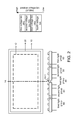
Please refer to FIG. 1, which shows a diagram of a LED backlight module according to the first embodiment of the present invention. The LED backlight module according to the first embodiment of the present invention is employed in a liquid crystal display apparatus. The backlight module in this embodiment is a side light type LED backlight module. As shown in the right of FIG. 1, a diagram of that a plurality of LEDs, classified according to positive voltage bin (Vf BIN) is disclosed. The positive voltage of the first voltage bin is the highest. The positive voltage of the fourth voltage bin is the lowest. The LEDs 60 belong to the first voltage bin. The LEDs 50 belong to the second voltage bin. The LEDs 40 belong to the third voltage bin. The LEDs belonging to the fourth voltage bin will not be used. The LEDs 40 are arranged in a first light group. The LEDs 50 are arranged in a second light group. The LEDs 60 are arranged in a third light group. The LED backlight module shown in FIG. 1 comprises a back plate 10, a light guide plate 20, a light bar 30 and a plurality of LEDs 40-60. The light bar 30 corresponds to the light guide plate 20 and is positioned at a side of the light guide plate 20 perpendicular to the display center line 14. The plurality of LEDs 40-60 is positioned at the light bar 30 and faces the incident surface of the light guide plate 20. The incident surface of the light guide plate 20 is a plane. The liquid crystal display apparatus comprises a display area 12 in accordance with the back plate 10 and overlaps therewith. The display area 12 has a display area center line 14 (AA area center line). The display area center line 14 has a center 14-1 corresponding to the LEDs. In this embodiment, the LEDs 40 (the first light group) belonging to the lowest positive voltage bin are positioned closest to the position of the center 14-1. The LEDs 60 (the third light group) belonging to the highest positive voltage bin are positioned farthest to the position of the center 14-1. The LEDs 50 (the second light group) are positioned among the LEDs 40 (the first light group) and the LEDs 60 (the third light group).
Please refer to FIG. 2. FIG. 2 shows a diagram of a LED backlight module according to the second embodiment of the present invention. The backlight module in this embodiment is a side light type LED backlight module. As shown in the right of FIG. 2, a diagram of that a plurality of LEDs, classified according to positive voltage bin (Vf BIN) is disclosed. The positive voltage of the first voltage bin is the highest. The positive voltage of the fourth voltage bin is the lowest. The LEDs 60 belong to the first voltage bin. The LEDs 50 belong to the second voltage bin. The LEDs 40 belong to the third voltage bin. The LEDs belonging to the fourth voltage bin will not be used. The LEDs 40 are arranged in a first light group. The LEDs 50 are arranged in a second light group. The LEDs 60 are arranged in a third light group. The LED backlight module comprises a back plate 10, a light guide plate 20, a light bar 30-1, a light bar 30-2 and a plurality of LEDs 40-60. The liquid crystal display apparatus comprises a display area 12 in accordance with the back plate 10 and overlaps therewith. The display area 12 has a display area center line 14. The display area center line 14 has a center 14-1 corresponding to the LEDs. The light bar 30-1 and the light bar 30-2 are symmetrically laid out regarding the center 14-1 and positioned at a side of the light guide plate 20 perpendicular to the display center line 14. The plurality of LEDs 40, 50 and 60 is positioned at the light bar 30-1 and the light bar 30-2 and faces the incident surface of the light guide plate 20. The incident surface of the light guide plate 20 is a plane. In this embodiment, the LEDs 40 (the first light group) belong the lowest positive voltage bin are positioned at the light bar 30-1 and the light bar 30-2 closest to the position of the center 14-1. The LEDs 60 (the third light group) belong the highest positive voltage bin are positioned at the light bar 30-1 and the light bar 30-2 farthest to the position of the center 14-1.
Please refer to FIG. 3, which shows a diagram of a LED backlight module according to the third embodiment of the present invention. The backlight module in this embodiment is a side light type LED backlight module. As shown in the right of FIG. 3, a diagram of that a plurality of LEDs, classified according to positive voltage bin (Vf BIN) is disclosed. The positive voltage of the first voltage bin is the highest. The positive voltage of the fourth voltage bin is the lowest. The LEDs 60 belong to the first voltage bin. The LEDs 50 belong to the second voltage bin. The LEDs 40 belong to the third voltage bin. The LEDs belonging to the fourth voltage bin will not be used. The LEDs 40 are arranged in a first light group. The LEDs 50 are arranged in a second light group. The LEDs 60 are arranged in a third light group. The LED backlight module comprises a back plate 10, a light guide plate 20, four light bars 30-1, 30-2, 30-3, 30-4 and a plurality of LEDs 40-60. The liquid crystal display apparatus comprises a display area 12 in accordance with the back plate 10 and overlaps therewith. The display area 12 has a display area center line 14. The display area center line 14 has a center 14-1 corresponding to the LEDs. The light bars 30-1, 30-2, 30-3, 30-4 are symmetrically laid out regarding the center 14-1 and positioned at a side of the light guide plate 20 perpendicular to the display center line 14. The LEDs 40-60 correspond to the light guide plate 20 and face the incident surface of the light guide plate 20. The incident surface of the light guide plate 20 is a plane. The light bars 30-2, 30-3 are closet to the center 14-1. The light bars 30-1, 30-4 are farthest to the center 14-1. The LEDs 40 (the first light group) are positioned at the light bars 30-2 and 30-3 closest to the position of the center 14-1. The LEDs 50 (the third light group) are positioned at the light bars 30-2 and 30-3 farther to the position of the center 14-1. The LEDs 60 (the third light group) are positioned farthest to the position of the center 14-1.
Please refer to FIG. 4, FIG. 5 and FIG. 6, which respectively show LED backlight modules according to the fourth, fifth and sixth embodiments of the present invention. The backlight modules in the fourth, fifth and sixth embodiments are similar to the backlight module in the third embodiment. As shown in FIG. 4, the difference is that the incident surface of the light guide plate 20-1 facing the light bars 30-1, 30-2, 30-3, 30-4 has a plurality of concaves. As shown in FIG. 5, the incident surface of the light guide plate 20-2 facing the light bars 30-1, 30-2, 30-3, 30-4 has a plurality of convexes in the fifth embodiment. As shown in FIG. 6, the incident surface of the light guide plate 20-3 facing the light bars 30-1, 30-2, 30-3, 30-4 is a jagged structure surface in the sixth embodiment.
Please refer to FIG. 7, which shows a diagram of a LED backlight module according to the seventh embodiment of the present invention. The backlight module in this embodiment is a direct light type LED backlight module. The LED backlight module comprises a back plate 10, a plurality of light bars 30-5 and a plurality of LEDs. The liquid crystal display apparatus comprises has a display area center line 14. The display area center line 14 has a center 14-1 corresponding to the LEDs around the central position of the back plate 10. The center 14-1 is substantially at the central position of the back plate 10. As shown in the lower of FIG. 7, a diagram of that a plurality of LEDs, classified according to positive voltage bin (Vf BIN) is disclosed. The plurality of LEDs is classified into four bins, the first voltage bin (V1), the second voltage bin (V2), the third voltage bin (V3) and the fourth voltage bin (V4). The positive voltage of the first voltage bin (V1) is the highest. The positive voltage of the fourth voltage bin (V4) is the lowest. The plurality of light bars 30-5 is laid out on the back plate 10. As shown in FIG. 7, the LEDs belonging to the fourth voltage bin will not be used. The LEDs belonging to the third voltage bin (V3) are positioned on the light bar at the center 14-1. The LEDs belonging to the second voltage bin (V2) are positioned on the light bars at the top, the bottom, the left and the right of the center 14-1. The LEDs belonging to the first voltage bin (V1) are positioned on the light bars at the upper right, the lower right, the upper left and the lower left of the center 14-1. However, please notice that that the amount of the light bar 30-5 is not specifically limited in this embodiment.
Please refer to FIG. 8, which shows a diagram of a LED backlight module according to the eighth embodiment of the present invention. The backlight module in this embodiment is a direct light type LED backlight module. As shown in the lower of FIG. 8, a diagram of that a plurality of LEDs, classified according to positive voltage bin (Vf BIN) is disclosed. The plurality of LEDs is classified into four bins, the first voltage bin (V1), the second voltage bin (V2), the third voltage bin (V3) and the fourth voltage bin (V4). The LED backlight module comprises a back plate 10 and a plurality of LEDs. The difference between the seventh embodiment and the eighth embodiment is that the LED backlight module does not comprise any light bars but the LEDs are directly laid out on the back plate 10. As shown in FIG. 8, the LEDs belonging to the third voltage bin (V3) are positioned around the center 14-1. The LEDs belonging to the second voltage bin (V2) are positioned at the top, the bottom, the left and the right of the center 14-1. The LEDs belonging to the first voltage bin (V1) are positioned at the upper right, the lower right, the upper left and the lower left of the center 14-1. However, please notice that that the amount of LED V1, V2, V3, V4 and their positions on the back plate 10 are not specifically limited in this embodiment.
Moreover, the present invention also provides a liquid crystal display apparatus utilizing any of the LED backlight modules described in the first embodiment˜the eighth embodiment. The LED backlight module of the liquid crystal display apparatus according to the present invention comprises a back plate and a plurality of LEDs. The back plate is positioned at the bottom of the backlight module and is a portion of the backlight module. The liquid crystal display apparatus has a display area in accordance with the back plate and overlaps therewith. The display area has a display area center line. The plurality of LEDs is classified to belong to several positive voltage bins, respectively. The display area center line has a center corresponding to the LEDs. The LEDs belonging to a lower positive voltage bin are positioned closer to the center and the LEDs belonging to a higher positive voltage bin are positioned farther to the center.
Please refer to FIG. 9, which shows an explanation diagram of raising an usage of the LEDs according to the present invention. As shown in FIG. 9( a), a diagram of that a plurality of LEDs for a backlight module, classified according to positive voltage bin (Vf BIN) in prior art is disclosed. Merely the LEDs belonging to the third voltage bin (V3) are used. However, according to the present invention, the LEDs belonging to the first, second and third voltage bins can be used for the backlight module. Furthermore, according to the first embodiment˜the eighth embodiment in the present invention, the LEDs belonging to a lower positive voltage bin are positioned closer to the center and the LEDs belonging to a higher positive voltage bin are positioned farther to the center. Therefore, the temperature around the center of the backlight module can be reduced to promote the LED temperature distribution. Accordingly, the brightness and chrominance at the center and the brightness and chrominance at periphery can be more uniformly equivalent.
As is understood by a person skilled in the art, the foregoing preferred embodiments of the present invention are illustrative rather than limiting of the present invention. It is intended that they cover various modifications and similar arrangements be included within the spirit and scope of the appended claims, the scope of which should be accorded the broadest interpretation so as to encompass all such modifications and similar structure.

Claims (18)

What is claimed is:
1. A backlight module, employed in a liquid crystal display apparatus, having a back plate and a plurality of Light emitting diodes, the liquid crystal display apparatus has a display area in accordance with the back plate and overlaps therewith, and the display area has a display area center line, and the display area center line has a center corresponding to the Light emitting diodes, characterized in that the Light emitting diodes are classified to belong to several positive voltage bins respectively, wherein the Light emitting diodes belonging to a lower positive voltage bin are positioned closer to the center and the Light emitting diodes belonging to a higher positive voltage bin are positioned farther from the center.
2. The backlight module of claim 1, characterized in that the backlight module is a direct light type backlight module.
3. The backlight module of claim 2, characterized in that the backlight module further comprises a plurality of light bars positioned on the back plate and the Light emitting diodes are positioned on the light bars.
4. The backlight module of claim 3, characterized in that the center is substantially at a center position of the back plate, the light bars are symmetrically laid out regarding the center and the Light emitting diodes are categorized into several light groups in accordance with the several positive voltage bins, wherein a light group belonging to a lower positive voltage bin is positioned on a light bar closer to the center and a light group belonging to a higher positive voltage bin is positioned on a light bar farther from the center, and a light group belonging to a positive voltage bin between the higher positive voltage bin and the lower positive voltage bin is positioned between the light group belonging to higher positive voltage bin and the light group belonging to the lower positive voltage bin.
5. The backlight module of claim 2, characterized in that the Light emitting diodes are directly laid out on the back plate.
6. The backlight module of claim 1, characterized in that the backlight module is a side light type backlight module further comprising a light guide plate positioned at a side perpendicular to the display center line.
7. The backlight module of claim 6, characterized in that the backlight module further comprises at least one light bar corresponding to the light guide plate wherein the said light bar is positioned at the side where the light guide plate is positioned, and the Light emitting diodes are positioned on the at least one light bar.
8. The backlight module of claim 7, characterized in that the at least one light bar is symmetrically laid out regarding the center and the Light emitting diodes are categorized into several light groups in accordance with the several positive voltage bins, wherein a light group belonging to a lower positive voltage bin is positioned on a light bar closer to the center and a light group belonging to a higher positive voltage bin is positioned on a light bar farther from the center, and a light group belonging to a positive voltage bin between the higher positive voltage bin and the lower positive voltage bin is positioned between the light group belonging to higher positive voltage bin and the light group belonging to the lower positive voltage bin.
9. The backlight module of claim 8, characterized in that the light groups respectively comprise Light emitting diodes classified to belong to the same positive voltage bin.
10. The backlight module of claim 6, characterized in that an incident surface of the light guide plate facing the at least one light bar is a plane or a jagged structure surface.
11. The backlight module of claim 7, characterized in that an incident surface of the light guide plate facing the at least one light bar is a plane or a jagged structure surface.
12. The backlight module of claim 8, characterized in that an incident surface of the light guide plate facing the at least one light bar is a plane or a jagged structure surface.
13. The backlight module of claim 9, characterized in that an incident surface of the light guide plate facing the at least one light bar is a plane or a jagged structure surface.
14. The backlight module of claim 6, characterized in that an incident surface of the light guide plate facing the at least one light bar comprises a plurality of concaves or a plurality of convexes.
15. The backlight module of claim 7, characterized in that an incident surface of the light guide plate facing the at least one light bar comprises a plurality of concaves or a plurality of convexes.
16. The backlight module of claim 8, characterized in that an incident surface of the light guide plate facing the at least one light bar comprises a plurality of concaves or a plurality of convexes.
17. The backlight module of claim 9, characterized in that an incident surface of the light guide plate facing the at least one light bar comprises a plurality of concaves or a plurality of convexes.
18. A liquid crystal display apparatus, comprising a backlight module, characterized in that the backlight module comprises:
a back plate, positioned at the bottom of the backlight module, the liquid crystal display apparatus has a display area in accordance with the back plate and overlaps therewith, the display area has a display area center line; and
a plurality of Light emitting diodes, classified to belong to several positive voltage bins respectively and the display area center line has a center corresponding to the Light emitting diodes,
wherein the Light emitting diodes belonging to a lower positive voltage bin are positioned closer to the center and the Light emitting diodes belonging to a higher positive voltage bin are positioned farther from the center.
US12/996,336 2010-07-30 2010-09-02 Backlight module and liquid crystal display apparatus Active 2031-10-13 US8610843B2 (en)

Applications Claiming Priority (3)

Application Number Priority Date Filing Date Title
CN2010102456792A CN101956935A (en) 2010-07-30 2010-07-30 Backlight module and liquid crystal display device
CN201010245679 2010-07-30
PCT/CN2010/076559 WO2012012957A1 (en) 2010-07-30 2010-09-02 Back light module and liquid crystal display device

Publications (2)

Publication Number Publication Date
US20120057103A1 US20120057103A1 (en) 2012-03-08
US8610843B2 true US8610843B2 (en) 2013-12-17

Family

ID=43484434

Family Applications (1)

Application Number Title Priority Date Filing Date
US12/996,336 Active 2031-10-13 US8610843B2 (en) 2010-07-30 2010-09-02 Backlight module and liquid crystal display apparatus

Country Status (3)

Country Link
US (1) US8610843B2 (en)
CN (1) CN101956935A (en)
WO (1) WO2012012957A1 (en)

Families Citing this family (5)

* Cited by examiner, † Cited by third party
Publication number Priority date Publication date Assignee Title
WO2012141098A1 (en) * 2011-04-13 2012-10-18 シャープ株式会社 Lighting device and display device
ITPD20120376A1 (en) 2012-12-12 2014-06-13 Automotive Lighting Italia Spa LIGHTING CIRCUIT, IN PARTICULAR WITH LED LIGHT SOURCES
TWI647521B (en) * 2014-09-29 2019-01-11 緯創資通股份有限公司 Backlight module and display having the same
CN211181603U (en) * 2019-12-06 2020-08-04 广州视源电子科技股份有限公司 Light-emitting circuit, backlight module and display
CN112162433A (en) * 2020-10-16 2021-01-01 业成科技(成都)有限公司 Backlight module and layout method of light emitting diodes thereof

Citations (13)

* Cited by examiner, † Cited by third party
Publication number Priority date Publication date Assignee Title
JP2002109936A (en) 2000-09-28 2002-04-12 Sanyo Electric Co Ltd Flat light source device and display device
CN101390004A (en) 2006-02-24 2009-03-18 飞利浦拉米尔德斯照明设备有限责任公司 Multi-colored led array with improved color uniformity
US20090097271A1 (en) * 2007-10-10 2009-04-16 Apple Inc. Led backlight for display systems
US20090135592A1 (en) * 2006-04-10 2009-05-28 Sharp Kabushiki Kaisha Led package, and illumination device and liquid crystal display device provided therewith
CN101622494A (en) 2007-04-26 2010-01-06 夏普株式会社 Light emitting element and liquid crystal display device
WO2010004797A1 (en) 2008-07-11 2010-01-14 シャープ株式会社 Illuminating device and liquid crystal display device
CN101634777A (en) 2009-02-27 2010-01-27 超亮显示系统(深圳)有限公司 Ultra-high brightness LED matrix straight-downward backlight module applied to large-scale LCD
CN101655639A (en) 2009-09-29 2010-02-24 上海交通大学 Side light type LCD backlight module comprising non-uniform linear light source
US20100053496A1 (en) * 2008-08-27 2010-03-04 Lg Display Co., Ltd. Back light unit and liquid crystal display device therewith
CN101666429A (en) 2008-09-03 2010-03-10 奇美电子股份有限公司 Light-emitting diode matrix, backlight module with same and liquid crystal display device
US20100245227A1 (en) * 2009-03-24 2010-09-30 Apple Inc. White point control in backlights
US20120057102A1 (en) * 2010-07-30 2012-03-08 Shenzhen China Star Optoelectronics Technology Co., Ltd. Backlight module
US20120113681A1 (en) * 2010-11-05 2012-05-10 Shenzhen China Star Optoelectronics Technology Co., Ltd. Lightbar module and backlight device

Patent Citations (13)

* Cited by examiner, † Cited by third party
Publication number Priority date Publication date Assignee Title
JP2002109936A (en) 2000-09-28 2002-04-12 Sanyo Electric Co Ltd Flat light source device and display device
CN101390004A (en) 2006-02-24 2009-03-18 飞利浦拉米尔德斯照明设备有限责任公司 Multi-colored led array with improved color uniformity
US20090135592A1 (en) * 2006-04-10 2009-05-28 Sharp Kabushiki Kaisha Led package, and illumination device and liquid crystal display device provided therewith
CN101622494A (en) 2007-04-26 2010-01-06 夏普株式会社 Light emitting element and liquid crystal display device
US20090097271A1 (en) * 2007-10-10 2009-04-16 Apple Inc. Led backlight for display systems
WO2010004797A1 (en) 2008-07-11 2010-01-14 シャープ株式会社 Illuminating device and liquid crystal display device
US20100053496A1 (en) * 2008-08-27 2010-03-04 Lg Display Co., Ltd. Back light unit and liquid crystal display device therewith
CN101666429A (en) 2008-09-03 2010-03-10 奇美电子股份有限公司 Light-emitting diode matrix, backlight module with same and liquid crystal display device
CN101634777A (en) 2009-02-27 2010-01-27 超亮显示系统(深圳)有限公司 Ultra-high brightness LED matrix straight-downward backlight module applied to large-scale LCD
US20100245227A1 (en) * 2009-03-24 2010-09-30 Apple Inc. White point control in backlights
CN101655639A (en) 2009-09-29 2010-02-24 上海交通大学 Side light type LCD backlight module comprising non-uniform linear light source
US20120057102A1 (en) * 2010-07-30 2012-03-08 Shenzhen China Star Optoelectronics Technology Co., Ltd. Backlight module
US20120113681A1 (en) * 2010-11-05 2012-05-10 Shenzhen China Star Optoelectronics Technology Co., Ltd. Lightbar module and backlight device

Non-Patent Citations (1)

* Cited by examiner, † Cited by third party
Title
English version of written opinion issued for PCT/CN2010/076559, mailing date May 12, 2011. *

Also Published As

Publication number Publication date
WO2012012957A1 (en) 2012-02-02
US20120057103A1 (en) 2012-03-08
CN101956935A (en) 2011-01-26

Similar Documents

Publication Publication Date Title
US20120057102A1 (en) Backlight module
TWI402571B (en) Backlight module with complementary color zone
CN103047578B (en) Direct-type backlight module structure
US8610843B2 (en) Backlight module and liquid crystal display apparatus
US20120026423A1 (en) Edge-lit backlight module and lcd using the same
CN102661535B (en) Direct type backlight module
US8780297B2 (en) Backlight module
US20120043895A1 (en) Led backlight module
US7163315B2 (en) Backlight module
US20200301202A1 (en) Backlight module and display device
CN101936487B (en) Backlight module
CN101338877B (en) Luminous diode array and backlight module group
CN101737670A (en) Direct-side lighting combined hybrid backlight
CN102072439B (en) Light source module and backlight device
US20120113681A1 (en) Lightbar module and backlight device
CN102720990A (en) Lateral type light-emitting diode (LED) backlight module with glass light guide plate
CN200993709Y (en) Backlight module
CN202647412U (en) Glass light guide plate side-entering type light-emitting diode (LED) backlight module
US7699497B2 (en) Backlight module and a liquid crystal display module using the same
US8426873B2 (en) LED package structure
CN102518985B (en) Area light source and backlight module using the same
JPWO2013099718A1 (en) Illumination device, backlight, liquid crystal display device, and television receiver
CN202647410U (en) Side LED backlight module of glass light guide plate
CN102278704A (en) Diffusion plate with supporting structure
CN100465727C (en) Backlight module and liquid crystal display module

Legal Events

Date Code Title Description
AS Assignment

Owner name: SHENZEN CHINA STAR OPTOELECTRONICS TECHNOLOGY CO.,

Free format text: ASSIGNMENT OF ASSIGNORS INTEREST;ASSIGNORS:CAO, QIAN;LIN, POYING;KUO, YICHENG;REEL/FRAME:025466/0147

Effective date: 20101105

STCF Information on status: patent grant

Free format text: PATENTED CASE

FEPP Fee payment procedure

Free format text: PAYOR NUMBER ASSIGNED (ORIGINAL EVENT CODE: ASPN); ENTITY STATUS OF PATENT OWNER: LARGE ENTITY

FPAY Fee payment

Year of fee payment: 4

MAFP Maintenance fee payment

Free format text: PAYMENT OF MAINTENANCE FEE, 8TH YEAR, LARGE ENTITY (ORIGINAL EVENT CODE: M1552); ENTITY STATUS OF PATENT OWNER: LARGE ENTITY

Year of fee payment: 8