EP2384817B1 - Lame annulaire pour ensembles de coupe de broyeuses - Google Patents
Lame annulaire pour ensembles de coupe de broyeuses Download PDFInfo
- Publication number
- EP2384817B1 EP2384817B1 EP20100004712 EP10004712A EP2384817B1 EP 2384817 B1 EP2384817 B1 EP 2384817B1 EP 20100004712 EP20100004712 EP 20100004712 EP 10004712 A EP10004712 A EP 10004712A EP 2384817 B1 EP2384817 B1 EP 2384817B1
- Authority
- EP
- European Patent Office
- Prior art keywords
- knife
- ring
- blades
- bars
- accordance
- Prior art date
- Legal status (The legal status is an assumption and is not a legal conclusion. Google has not performed a legal analysis and makes no representation as to the accuracy of the status listed.)
- Active
Links
- 235000013372 meat Nutrition 0.000 claims description 31
- 239000000463 material Substances 0.000 claims description 16
- 238000010008 shearing Methods 0.000 claims description 6
- 235000013305 food Nutrition 0.000 claims description 5
- 239000002994 raw material Substances 0.000 description 21
- 238000011144 upstream manufacturing Methods 0.000 description 19
- 239000007787 solid Substances 0.000 description 11
- 230000035515 penetration Effects 0.000 description 7
- 238000000034 method Methods 0.000 description 5
- 230000008569 process Effects 0.000 description 5
- 230000009471 action Effects 0.000 description 3
- 238000000926 separation method Methods 0.000 description 3
- 230000003247 decreasing effect Effects 0.000 description 2
- 230000000694 effects Effects 0.000 description 2
- 230000000149 penetrating effect Effects 0.000 description 2
- 230000009467 reduction Effects 0.000 description 2
- 230000002829 reductive effect Effects 0.000 description 2
- 230000002411 adverse Effects 0.000 description 1
- 230000007423 decrease Effects 0.000 description 1
- 230000001627 detrimental effect Effects 0.000 description 1
- 239000012636 effector Substances 0.000 description 1
- 238000000265 homogenisation Methods 0.000 description 1
- 230000003993 interaction Effects 0.000 description 1
- 230000009191 jumping Effects 0.000 description 1
- 230000000670 limiting effect Effects 0.000 description 1
- 230000036961 partial effect Effects 0.000 description 1
Images

Classifications
-
- B—PERFORMING OPERATIONS; TRANSPORTING
- B02—CRUSHING, PULVERISING, OR DISINTEGRATING; PREPARATORY TREATMENT OF GRAIN FOR MILLING
- B02C—CRUSHING, PULVERISING, OR DISINTEGRATING IN GENERAL; MILLING GRAIN
- B02C18/00—Disintegrating by knives or other cutting or tearing members which chop material into fragments
- B02C18/30—Mincing machines with perforated discs and feeding worms
- B02C18/36—Knives or perforated discs
- B02C18/362—Knives
Definitions
- the invention relates to a ring knife for multi-part, consisting of stationary perforated discs and at least one rotary knife cutting sets of crushing machines, especially for meat grinders and the like, comprising an inlet side and an outflow side having knife body with a hub and an outer ring and a plurality extending between the hub and outer ring Knife blades carrying knife blades which, together with the outer ring and the knife hub, limit knife spaces, as well as cutter blades carrying knife blades which extend from the outer ring into the knife spaces. Furthermore, the invention is directed to crushers with such ring knives.
- Such ring knives work together in sets of fixed perforated discs, it being advantageous that, in particular when mincing meat, up to 80% of the processed material conveyed by the working screw of a meat grinder is pressed onto the outer region of the perforated disc and fastened by the outer ring and only in the outer ring Effective area of the perforated disc Hanging knife blades a higher throughput is achieved, ie a homogenization of the throughput is achieved by the perforated disc.
- the comminution process takes place at least in two phases.
- a coarse comminution phase takes the first perforated disc ("entrance hole disc” or “rough perforated disc”) with comparatively large openings the respective raw material in a large, mechanically compact form and it is at the exit or downstream side of the perforated disc with the side facing knife blades means Shear action made a coarse crushing of the raw material. The shearing action is caused by the interaction of the knife blades with the edges of the perforated disc bores. In this process occur due to the material compactness of the raw material on large forces, so that the knives or knife carrier in this area must be very strongly dimensioned.
- the knife is located between a rough perforated disc and a fine perforated disc, wherein the knife is preferably designed as a ring knife and present between the substantially radially extending cutter bar of the ring diameter on both sides limited by the perforated disc cutter chambers.
- raw material penetrating into the holes of the fine perforated disk can only leave the fine perforated disk again if it is severed directly after penetration into the corresponding bore by the shearing action of the knife blades on the knife-side bore edge. If there is no blade available for this required separation process immediately after penetration of the raw material into the corresponding bore of the fine perforated disc, the raw material penetrating into the perforated disc bore is again pushed out of the bore, ie it can not be cut uniformly over the entire perforated disc surface, since the distance between the Successively effective knife blades for the hole assembly is given at a given rotational movement of the knife is too large. With standard knives, the cutting performance can easily be reduced by up to 60%.
- each hole opening represents a single cutting tool and these individual cutting tools can only work if the openings or holes in the perforated disks are unobstructed by the cutter blades carrying the knife blades available.
- the material to be processed can not simultaneously penetrate into all holes due to the applied thrust pressure, as a result of which the perforated disc power decreases.
- Conventionally designed knife bodies often obscure 30% to 40% of the perforated disc openings and thus reduce the number of effective cutting tools of the perforated disc.
- the known standard knives are designed for maximum mechanical load and accordingly the knife blades carrying the cutter bar correspondingly large, which has the consequence that in the conveying direction of the raw material undesirably large flow resistance arise and this spatially large cutter bar cover by their surface a large part of the perforated disc surface or the individual cutting tools forming holes of the perforated disc.
- the object of the invention is therefore in particular, a ring cutter of the type described in such a way that the different mechanical stresses of the successive cutting sequences can be taken into account when the mechanical state of the raw material has changed, and the efficiency of the cutting sets is substantially increased.
- inflow side is used for the knife side, which is arranged upstream in the flow direction of the material to be crushed.
- outlet side corresponds to the side of the knife body, which is arranged downstream in the direction of the flow.
- direction of the flow is defined by the direction in which moves the material to be crushed in the crushing process through the knife chambers of the knife body.
- blade is used herein to refer to those elements of the blade having cutting edges.
- the design of the knife chambers according to the invention achieves, inter alia, that the forces acting on the ring knife are taken into account practically separately according to the rough section, ie, a large load, and a fine cut, ie, a lower load. Due to the increased number of downstream knife blades in comparison to the inflow side it is achieved that the advantageously high cutting sequences are achieved, so that an optimum penetration rate of the raw material into the holes ensures and the material can be removed again from the holes.
- the solid-diameter bars preferably have a cross-section which reduces toward the outflow side.
- the Vollmesserbalken can accordingly have on the higher loaded side about three times the material cross section compared to the material cross section on the fine cut side. Since the Vollmesserbalken to the fine perforated disc directed towards accordingly have a decreasing cross-section, ie can be wedge-shaped, corresponding Lochularwirk Structure is free on the Feinlochharinseite.
- the essential for the invention extension of the knife chambers in the flow direction of the knife body is preferably by appropriate Wandungsschrägen of solid blade and / or knife blade and / or outer ring and / or hub reached. Preferably, all these measures are used simultaneously.
- the simultaneous shearing or separating cut must be at least substantially secured with all knife blades on the perforated disc. In this way, the knife and orifice plate performance compared to the known arrangement can be easily increased by 80% and even up to 100%.
- the invention also includes a device for mincing food, in particular for mincing meat and the like, with at least one perforated disc ring cutter set, in which the inflow side of at least one perforated disc is assigned a ring knife of the type described with its downstream side ,
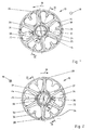
- FIGS. 1 to 4 show a ring knife 10 of a cutting set of a food crusher, for example a meat grinder, which rotates about an axis 12.
- the knife is driven by a shaft, not shown, which cooperates positively with the central two-edged opening 14.
- the knife rotates in operation in the direction of arrow 16.
- Fig. 1 shows the plan view of the downstream side of the knife
- Fig. 2 a plan view of the inflow side shows.
- the flow direction of the material to be shredded is accordingly indicated by the symbols 18.
- meat is the material to be shredded.
- meat is always referred to as material to be comminuted, without this being to be understood as limiting.
- full blade bars 22 extend outwardly.
- six such Vollmesserbalken 22 are provided, of which for clarity, only a part is provided with reference numeral.
- the embodiment shows six equally spaced solid knife bars 22. Other numbers are also possible, for example three, four or more.
- the full blade bars 22 terminate at an outer ring 24, which may for example have an outer diameter of 15 to 20 cm.
- the thickness of the knife body in the direction of flow is, for example, one to a few centimeters.
- the full blade bars 22 comprise on the downstream side of the blade 10, which in Fig. 1 visible, knife blades 26, of which in turn only a few are provided with reference numerals. They serve to separate the meat which has passed through the openings 34 of the knife 10.
- knife blades 26 of which in turn only a few are provided with reference numerals. They serve to separate the meat which has passed through the openings 34 of the knife 10.
- the in Fig. 2 is shown, the Vollmesserbalken 22 knife blades 28, of which also only a few are provided with reference numerals.
- Both the knife blades 26 on the downstream side of the blade 10, and the knife blades 28 on the upstream side of the blade 10 are not exactly aligned radially. Instead, the inner end of the knife blades 26, 28 (and thus also the knife edges) precede the outer end, which is farther from the hub 20, in the direction of rotation 16 of the rotating knife 10, thereby achieving good shearing of the meat.
- the orientation of the cutting is chosen the other way around, so in particular the ends of the knife blades close to the hub run after the ends remote from the hub in the direction of movement of the rotating blade. Such an embodiment ensures that the meat moves in the openings towards the center.
- FIG. 4 The cross section of a metering bar 22 is in Fig. 4 shown.
- Fig. 1 and 2 is the line of sight of Fig. 4 shown on this cross section with IV-IV.
- Fig. 4 the flow direction of the meat is again denoted by 18.
- the line of sight in Fig. 1 is visible in is Fig. 4 denoted by I.
- the line of sight in Fig. 2 is visible in is Fig. 4 denoted by II.
- Arrow 16 again indicates the direction of movement of the cutter bar 22 when the knife 10 is rotating.
- Fig. 4 recognizable that on the trailing in the direction of rotation 16 of the knife side of the Vollmesserbens 22 bevel 30 is provided, which causes the Vollmesserbalken 22 on the upstream side of the blade 10 is wider than on the downstream side.
- the support cross-sectional width 46 of a full-diameter bar 22 is thus greater on the inflow side than the support cross-sectional width 48 on the outflow side.
- the chamfers 30 are also in Fig. 1 visible, and here they are provided for clarity only in some of the Vollmesserbalken 22 with reference numerals.
- the chamfers 30 extend in this embodiment along the entire length of the respective Vollmesserbalkens 22 and along the outer ring 24th
- chamfer 30 is provided, but, for example, a concave shape, which is designed such that the Vollmesserbalken are wider on the upstream side than on the downstream side.
- a concave shape is in Fig. 5 wherein reference numeral 32 denotes the concave, in the direction of rotation 16 of the rotating blade 10 trailing surface of the Vollmesserbalkens 22.
- Two adjacent solid blade bars 22 and outer ring 24 each form openings 34 in the blade which act as individual pressure chambers.
- the bevels 30 and the concave surfaces 32 ensure that the openings 34 expand in the direction of flow 18.
- the achievable by reducing the width of the Vollmesserbalken 22 Extension of the openings 34 in the direction of flow 18 of the meat can be, for example, 30% of the opening size of the openings 34.
- these cutter blades 36 carry knife blades 38, which point in the direction of the hub 20.
- these knife edges are not exactly aligned radially. Instead, they are arranged obliquely so that the ends of the knife blades close to the ends run ahead of the ends in the direction of movement 16 of the rotating blade 10, whereby a good shearing off of the meat is achieved.
- the orientation of the cutting is chosen the other way around, so in particular the ends of the knife blades close to the hub run after the ends remote from the hub in the direction of movement of the rotating blade.
- exactly one partial knife bar 36 is arranged between each two solid cutter bars 22.
- two or more metering blades 36 are provided with corresponding cutter blades 38 between two Vollmesserbalken 22.
- Still other embodiments provide that not in all openings 34 between two Vollmesserbalken 22 one or more Operamesserbalken 36 are provided.
- Fig. 3 shows a section through the knife 10, the direction of view of this section in the Fig. 1 and 2 marked with III-III.
- the flow direction of the meat is again indicated by the arrow 18.
- the direction II one looks at the blade surface 40 of the upstream side of the blade 10.
- the blade surface 40 corresponds to the blade plane which is formed by the cutting edges of the blade blades 28 of the full blade 22 on the inflow side.
- the described embodiment of the knife 10 according to the invention acts as follows.
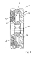
- FIG Fig. 6 An exemplary cutting set 54 with a knife 10 is shown in FIG Fig. 6 shown.
- the knife 10 rotates in this embodiment about the axis 12 between two fixed perforated discs 50 and 52nd
- the first perforated disc 50 which at the in Fig. 2 visible upstream side of the blade 10 has, in comparison to the second perforated disc 52, which at the in Fig. 1 visible downstream side of the blade 10 is arranged, larger holes 56 in a correspondingly smaller number per area.
- the second perforated disk 52 is therefore also referred to as a fine perforated disk and the first perforated disk 50 as a rough perforated disk.
- the pinhole disk 52 has twenty-two to fifty holes 58, and the rough hole disk 50 has three to seven holes 56.
- the holes 56 in the rough hole disk 50 and the holes 58 in the pinhole disk 52 are shown in FIG Fig. 6 only partially provided with reference numbers.
- the meat enters the openings 34 of the rotating blade 10 through the holes 56 of the roughing hole 50 located on the upstream side of the blade 10.
- the knife blades 28 on the upstream side of the blade 10 separate the meat that collects in the openings 34.
- the entry of the meat into the openings 34 is not substantially hindered by the metering blades 36, since these are at least partially set back on the upstream side of the blade 10, as shown in FIG Fig. 3 is visible.
- the meat entered into the openings 34 is pressed onto the fine perforated disk 52, which adjoins the rotating blade 10 in the cutting set in the direction of flow 18 and is likewise generally stationary.
- This fine perforated disc 52 has more and smaller holes 58 than the rough perforated disc 50. Because the solid carbide blades 22 on the downstream side of the blade 10 have a smaller span width as on the upstream side, it is ensured that the meat located in an opening 34 can hit a larger number of holes 58 in the fine perforated disk 52 than if the solid blade bars 22 had a constant width in the throughflow direction 18.
- the meat which enters through the openings 34 in the holes 58 of the subsequent fine perforated disc 52 is separated in particular by the knife blades 26 on the full blade bar 22.
- a separation is effected in particular in the radially outer region of the blade 10 by the blades 38 on the metering blade 36. In this way, the increased discharge performance is taken into account by the increasing cross sections of the openings 34.
- the described embodiment of the knife of a cutting set of a food shredder combines several advantages.
- By reducing the width of the Vollmesserbalken 22 in the direction of flow 18 of the meat through the chamfers 30 ensures that on the downstream side of the knife 10 a larger area and thus a larger number of holes 58 of the subsequent fine perforated disc 52 is acted upon by the meat than in a conventional Knife.
- the reduction in the width of the solid blade bars 22 is not detrimental to the stability of the blade as there are only about 25% of the rotational forces on the downstream side as compared to about 75% of the rotational forces occurring on the upstream side. On the thus far more loaded upstream side of the Vollmesserbalken 22 are wider.
- the entry of the meat into the openings 34 is not or not substantially hindered. Nevertheless, it will open the outflow side of the blade 10 by the Operamesserbalken 36 with the blades 38 reaches a high cutting performance, so that the guaranteed by the enlargement of the openings 34 performance increase can be processed and cut well especially on the downstream side.
Landscapes
- Engineering & Computer Science (AREA)
- Food Science & Technology (AREA)
- Crushing And Pulverization Processes (AREA)
Claims (10)
- Couteau annulaire (10) pour des kits de coupe (54) en plusieurs parties, composé de plaques à trous stationnaires (50, 52) et d'au moins un couteau (10) rotatif, pour des machines de comminution, en particulier pour hachoirs à viande et similaires,
comprenant un corps de couteau présentant un côté entrée et un côté sortie, avec un moyeu (20) et une bague extérieure (24), ainsi que plusieurs barreaux-couteaux pleins (22), s'étendant entre le moyeu (20) et la bague extérieure (24), et portant des lames de couteau (26, 28) qui délimitent des logements à couteau (34) conjointement avec la bague extérieure (24) et le moyeu (20), ainsi que des barreaux-couteaux partiels (36) qui portent également des lames de couteau (38) et qui s'étendent en partant de la bague extérieure (24) jusque dans les logements à couteau (34),
caractérisé en ce que le nombre des lames de couteau (36, 38) actives disposées du côté sortie est supérieur au nombre des lames de couteau (28) actives disposées du côté entrée, et
en ce que les logements à couteau (34) s'élargissent en direction (18) de l'écoulement traversant du corps de couteau (10). - Couteau annulaire selon la revendication 1,
caractérisé en ce que les barreaux-couteaux pleins (22) présentent au moins en partie, partant d'une dimension maximum (46) de leur section transversale, du côté entrée, une section qui va en se rétrécissant en direction du côté sortie. - Couteau annulaire selon la revendication 1 ou 2,
caractérisé en ce que les barreaux-couteaux partiels (36) présentent au moins en partie une section qui diminue sur leur longueur, en partant de la bague extérieure (24). - Couteau annulaire selon la revendication 3,
caractérisé en ce que les surfaces de délimitation du côté entrée des barreaux-couteaux partiels (36) sont écartées par rapport au plan de couteau (40) formé du côté entrée par les arêtes de coupe des lames de couteau (28) du côté entrée des barreaux-couteaux pleins (22), et sont en particulier écartées de façon croissante depuis la bague extérieure (24) vers l'intérieur. - Couteau annulaire selon l'une des revendications 1 à 4,
caractérisé en ce que l'élargissement, de préférence conique, des logements à couteau (34) est formé par des parties obliques (30) des parois des barreaux-couteaux pleins (23) ou des barreaux-couteaux partiels (36) et/ou la bague extérieure (24) ou le moyeu (20). - Couteau annulaire selon l'une des revendications 1 à 5,
caractérisé en ce que les barreaux-couteaux pleins (22) et/ou les barreaux-couteaux partiels (36) sont biseautés sur le côté postérieur dans la direction de rotation (16) du couteau. - Couteau annulaire selon l'une des revendications 1 à 6,
caractérisé en ce que le corps de couteau est composé de deux corps de couteaux partiels appliqués l'un contre l'autre, l'un des corps de couteau partiel portant les lames de couteau formant le plan de couteau du côté entrée et l'autre corps de couteau partiel portant les lames de couteau formant le plan de couteau du côté sortie. - Appareil pour la comminution de produits alimentaires, en particulier pour hacher de la viande et des produits similaires, comprenant au moins un kit de coupe (54) composé de plaques à trous et de couteaux annulaires,
caractérisé en ce que le côté sortie d'un couteau annulaire (10) selon l'une ou plusieurs des revendications 1 à 7 est associé au côté entrée d'au moins une plaque à trous (52). - Appareil selon la revendication 8,
caractérisé en ce que le couteau annulaire (10) est agencé en rotation entre deux plaques à trous stationnaires (50, 52), et la plaque à trous (52) du côté sortie comporte un nombre de trous plus important et des trous plus petits (58) que la plaque à trous (50) du côté entrée. - Appareil selon la revendication 9,
caractérisé en ce que la taille des trous et le nombre de trous de la plaque à trous (52) du côté sortie ainsi que le nombre de lames de couteau et le nombre de couteaux associés sont ajustés en fonction des propriétés du matériau à traiter de telle façon que l'on obtient des découpes sensiblement simultanées sur la totalité de la surface de la plaque à trous.
Priority Applications (1)
| Application Number | Priority Date | Filing Date | Title |
|---|---|---|---|
| EP20100004712 EP2384817B1 (fr) | 2010-05-04 | 2010-05-04 | Lame annulaire pour ensembles de coupe de broyeuses |
Applications Claiming Priority (1)
| Application Number | Priority Date | Filing Date | Title |
|---|---|---|---|
| EP20100004712 EP2384817B1 (fr) | 2010-05-04 | 2010-05-04 | Lame annulaire pour ensembles de coupe de broyeuses |
Publications (2)
| Publication Number | Publication Date |
|---|---|
| EP2384817A1 EP2384817A1 (fr) | 2011-11-09 |
| EP2384817B1 true EP2384817B1 (fr) | 2013-07-24 |
Family
ID=42801093
Family Applications (1)
| Application Number | Title | Priority Date | Filing Date |
|---|---|---|---|
| EP20100004712 Active EP2384817B1 (fr) | 2010-05-04 | 2010-05-04 | Lame annulaire pour ensembles de coupe de broyeuses |
Country Status (1)
| Country | Link |
|---|---|
| EP (1) | EP2384817B1 (fr) |
Families Citing this family (1)
| Publication number | Priority date | Publication date | Assignee | Title |
|---|---|---|---|---|
| DE102013018785A1 (de) * | 2013-11-08 | 2015-05-13 | Inofex Fleisch-, Lebensmitteltechnik Und -Technologie Gmbh | Messergestaltung zur Steigerung der Leistung von vorzugsweise nach dem Wolfwirkprinzip arbeitenden Schneidemaschinen |
Family Cites Families (3)
| Publication number | Priority date | Publication date | Assignee | Title |
|---|---|---|---|---|
| DE1153287B (de) * | 1961-10-27 | 1963-08-22 | Kristian Isak William Jensen | Rotierendes Schneidmesser fuer Fleischwoelfe |
| DE3215950A1 (de) | 1982-04-29 | 1983-11-03 | Theodor Jopp KG, 8740 Bad Neustadt | Schneidsatz fuer fleischwoelfe |
| DE4301787C1 (de) | 1993-01-23 | 1994-08-25 | Inofex Fleisch Lebensmitteltec | Messer für Fleischwölfe |
-
2010
- 2010-05-04 EP EP20100004712 patent/EP2384817B1/fr active Active
Also Published As
| Publication number | Publication date |
|---|---|
| EP2384817A1 (fr) | 2011-11-09 |
Similar Documents
| Publication | Publication Date | Title |
|---|---|---|
| EP2987557B1 (fr) | Machine de broyage d'un produit | |
| EP2218507A2 (fr) | Dispositif de broyage de matériaux de chargement dotés d'éléments de démoulage | |
| EP3202290A1 (fr) | Broyeuse, moulin, dispositif de préparation de café comprenant un broyeur et procédé de broyage | |
| DE102007058127A1 (de) | Vorrichtung zum Auflösen des Verbundes von im Verbund vorliegendem Aufgabegut | |
| WO2007000300A1 (fr) | Moulin a couteau | |
| DE102010055786B4 (de) | Lochscheibensystem | |
| EP2384817B1 (fr) | Lame annulaire pour ensembles de coupe de broyeuses | |
| DE102019108306A1 (de) | Schneidmühle zum schneidenden Zerkleinern von Proben | |
| EP2311568B1 (fr) | Ensemble de coupe doté d'un compteur de bague d'écartement de sécurité | |
| DE2943567A1 (de) | Reisszahnwalze und damit bestueckte reisswalenzerkleinerungsmaschinen | |
| DE102010055785B4 (de) | Konti Kutter Vakuum | |
| WO2018050809A1 (fr) | Rotor de hachage pour un dispositif de broyage, en particulier hachoir | |
| EP2452554A1 (fr) | Installation de machine pour le traitement de produits agricoles | |
| DE102013104587B4 (de) | Profilierte Zerkleinerungsscheibe, Zerkleinerungswalze und Zerkleinerungseinrichtung für Erntemaschinen | |
| EP3515602B1 (fr) | Broyeur fin | |
| EP2548648B1 (fr) | Broyeur pour le broyage de matière | |
| AT374377B (de) | Vorrichtung zur zerkleinerung von landwirtschaftlichem gut | |
| DE2748555A1 (de) | Schrot- und siliermaschine fuer feldfruechte | |
| DE102004012201B4 (de) | Spänebrecher | |
| DE102015203790B4 (de) | Halbfeste, plastische und plastoelastische biologische Rohstoffe fein zerkleinernde und/oder emulgierende Einrichtung | |
| DE202017000378U1 (de) | Messertrommel zum Zerkleinern von Holz | |
| DE29724035U1 (de) | Schneidrotor sowie Schneidmühle zur Zerkleinerung von Kunststoffen | |
| DE10048886A1 (de) | Vorrichtung zum Zerkleinern von Aufgabegut mit einem um eine Drehachse rotierenden Zerkleinerungssystem | |
| DE2216640C3 (de) | Schneidmühlenrotor | |
| DE102020132349A1 (de) | Vorrichtung zum Zerkleinern insbesondere von Fleisch |
Legal Events
| Date | Code | Title | Description |
|---|---|---|---|
| AK | Designated contracting states |
Kind code of ref document: A1 Designated state(s): AL AT BE BG CH CY CZ DE DK EE ES FI FR GB GR HR HU IE IS IT LI LT LU LV MC MK MT NL NO PL PT RO SE SI SK SM TR |
|
| AX | Request for extension of the european patent |
Extension state: BA ME RS |
|
| PUAI | Public reference made under article 153(3) epc to a published international application that has entered the european phase |
Free format text: ORIGINAL CODE: 0009012 |
|
| 17P | Request for examination filed |
Effective date: 20111223 |
|
| GRAP | Despatch of communication of intention to grant a patent |
Free format text: ORIGINAL CODE: EPIDOSNIGR1 |
|
| GRAJ | Information related to disapproval of communication of intention to grant by the applicant or resumption of examination proceedings by the epo deleted |
Free format text: ORIGINAL CODE: EPIDOSDIGR1 |
|
| GRAP | Despatch of communication of intention to grant a patent |
Free format text: ORIGINAL CODE: EPIDOSNIGR1 |
|
| INTG | Intention to grant announced |
Effective date: 20130327 |
|
| GRAS | Grant fee paid |
Free format text: ORIGINAL CODE: EPIDOSNIGR3 |
|
| GRAA | (expected) grant |
Free format text: ORIGINAL CODE: 0009210 |
|
| AK | Designated contracting states |
Kind code of ref document: B1 Designated state(s): AL AT BE BG CH CY CZ DE DK EE ES FI FR GB GR HR HU IE IS IT LI LT LU LV MC MK MT NL NO PL PT RO SE SI SK SM TR |
|
| REG | Reference to a national code |
Ref country code: GB Ref legal event code: FG4D Free format text: NOT ENGLISH |
|
| REG | Reference to a national code |
Ref country code: CH Ref legal event code: EP |
|
| REG | Reference to a national code |
Ref country code: AT Ref legal event code: REF Ref document number: 623080 Country of ref document: AT Kind code of ref document: T Effective date: 20130815 |
|
| REG | Reference to a national code |
Ref country code: IE Ref legal event code: FG4D Free format text: LANGUAGE OF EP DOCUMENT: GERMAN |
|
| REG | Reference to a national code |
Ref country code: DE Ref legal event code: R096 Ref document number: 502010004093 Country of ref document: DE Effective date: 20130919 |
|
| REG | Reference to a national code |
Ref country code: NL Ref legal event code: T3 |
|
| REG | Reference to a national code |
Ref country code: LT Ref legal event code: MG4D |
|
| PG25 | Lapsed in a contracting state [announced via postgrant information from national office to epo] |
Ref country code: IS Free format text: LAPSE BECAUSE OF FAILURE TO SUBMIT A TRANSLATION OF THE DESCRIPTION OR TO PAY THE FEE WITHIN THE PRESCRIBED TIME-LIMIT Effective date: 20131124 Ref country code: HR Free format text: LAPSE BECAUSE OF FAILURE TO SUBMIT A TRANSLATION OF THE DESCRIPTION OR TO PAY THE FEE WITHIN THE PRESCRIBED TIME-LIMIT Effective date: 20130724 Ref country code: NO Free format text: LAPSE BECAUSE OF FAILURE TO SUBMIT A TRANSLATION OF THE DESCRIPTION OR TO PAY THE FEE WITHIN THE PRESCRIBED TIME-LIMIT Effective date: 20131024 Ref country code: LT Free format text: LAPSE BECAUSE OF FAILURE TO SUBMIT A TRANSLATION OF THE DESCRIPTION OR TO PAY THE FEE WITHIN THE PRESCRIBED TIME-LIMIT Effective date: 20130724 Ref country code: CY Free format text: LAPSE BECAUSE OF FAILURE TO SUBMIT A TRANSLATION OF THE DESCRIPTION OR TO PAY THE FEE WITHIN THE PRESCRIBED TIME-LIMIT Effective date: 20130731 Ref country code: SE Free format text: LAPSE BECAUSE OF FAILURE TO SUBMIT A TRANSLATION OF THE DESCRIPTION OR TO PAY THE FEE WITHIN THE PRESCRIBED TIME-LIMIT Effective date: 20130724 Ref country code: PT Free format text: LAPSE BECAUSE OF FAILURE TO SUBMIT A TRANSLATION OF THE DESCRIPTION OR TO PAY THE FEE WITHIN THE PRESCRIBED TIME-LIMIT Effective date: 20131125 |
|
| PG25 | Lapsed in a contracting state [announced via postgrant information from national office to epo] |
Ref country code: GR Free format text: LAPSE BECAUSE OF FAILURE TO SUBMIT A TRANSLATION OF THE DESCRIPTION OR TO PAY THE FEE WITHIN THE PRESCRIBED TIME-LIMIT Effective date: 20131025 Ref country code: SI Free format text: LAPSE BECAUSE OF FAILURE TO SUBMIT A TRANSLATION OF THE DESCRIPTION OR TO PAY THE FEE WITHIN THE PRESCRIBED TIME-LIMIT Effective date: 20130724 Ref country code: LV Free format text: LAPSE BECAUSE OF FAILURE TO SUBMIT A TRANSLATION OF THE DESCRIPTION OR TO PAY THE FEE WITHIN THE PRESCRIBED TIME-LIMIT Effective date: 20130724 Ref country code: PL Free format text: LAPSE BECAUSE OF FAILURE TO SUBMIT A TRANSLATION OF THE DESCRIPTION OR TO PAY THE FEE WITHIN THE PRESCRIBED TIME-LIMIT Effective date: 20130724 Ref country code: FI Free format text: LAPSE BECAUSE OF FAILURE TO SUBMIT A TRANSLATION OF THE DESCRIPTION OR TO PAY THE FEE WITHIN THE PRESCRIBED TIME-LIMIT Effective date: 20130724 |
|
| PG25 | Lapsed in a contracting state [announced via postgrant information from national office to epo] |
Ref country code: CY Free format text: LAPSE BECAUSE OF FAILURE TO SUBMIT A TRANSLATION OF THE DESCRIPTION OR TO PAY THE FEE WITHIN THE PRESCRIBED TIME-LIMIT Effective date: 20130724 |
|
| PG25 | Lapsed in a contracting state [announced via postgrant information from national office to epo] |
Ref country code: SK Free format text: LAPSE BECAUSE OF FAILURE TO SUBMIT A TRANSLATION OF THE DESCRIPTION OR TO PAY THE FEE WITHIN THE PRESCRIBED TIME-LIMIT Effective date: 20130724 Ref country code: EE Free format text: LAPSE BECAUSE OF FAILURE TO SUBMIT A TRANSLATION OF THE DESCRIPTION OR TO PAY THE FEE WITHIN THE PRESCRIBED TIME-LIMIT Effective date: 20130724 Ref country code: DK Free format text: LAPSE BECAUSE OF FAILURE TO SUBMIT A TRANSLATION OF THE DESCRIPTION OR TO PAY THE FEE WITHIN THE PRESCRIBED TIME-LIMIT Effective date: 20130724 Ref country code: RO Free format text: LAPSE BECAUSE OF FAILURE TO SUBMIT A TRANSLATION OF THE DESCRIPTION OR TO PAY THE FEE WITHIN THE PRESCRIBED TIME-LIMIT Effective date: 20130724 Ref country code: CZ Free format text: LAPSE BECAUSE OF FAILURE TO SUBMIT A TRANSLATION OF THE DESCRIPTION OR TO PAY THE FEE WITHIN THE PRESCRIBED TIME-LIMIT Effective date: 20130724 |
|
| PG25 | Lapsed in a contracting state [announced via postgrant information from national office to epo] |
Ref country code: IT Free format text: LAPSE BECAUSE OF FAILURE TO SUBMIT A TRANSLATION OF THE DESCRIPTION OR TO PAY THE FEE WITHIN THE PRESCRIBED TIME-LIMIT Effective date: 20130724 Ref country code: ES Free format text: LAPSE BECAUSE OF FAILURE TO SUBMIT A TRANSLATION OF THE DESCRIPTION OR TO PAY THE FEE WITHIN THE PRESCRIBED TIME-LIMIT Effective date: 20130724 |
|
| PLBE | No opposition filed within time limit |
Free format text: ORIGINAL CODE: 0009261 |
|
| STAA | Information on the status of an ep patent application or granted ep patent |
Free format text: STATUS: NO OPPOSITION FILED WITHIN TIME LIMIT |
|
| 26N | No opposition filed |
Effective date: 20140425 |
|
| REG | Reference to a national code |
Ref country code: DE Ref legal event code: R097 Ref document number: 502010004093 Country of ref document: DE Effective date: 20140425 |
|
| PG25 | Lapsed in a contracting state [announced via postgrant information from national office to epo] |
Ref country code: LU Free format text: LAPSE BECAUSE OF FAILURE TO SUBMIT A TRANSLATION OF THE DESCRIPTION OR TO PAY THE FEE WITHIN THE PRESCRIBED TIME-LIMIT Effective date: 20140504 |
|
| REG | Reference to a national code |
Ref country code: CH Ref legal event code: PL |
|
| PG25 | Lapsed in a contracting state [announced via postgrant information from national office to epo] |
Ref country code: MC Free format text: LAPSE BECAUSE OF FAILURE TO SUBMIT A TRANSLATION OF THE DESCRIPTION OR TO PAY THE FEE WITHIN THE PRESCRIBED TIME-LIMIT Effective date: 20130724 Ref country code: LI Free format text: LAPSE BECAUSE OF NON-PAYMENT OF DUE FEES Effective date: 20140531 Ref country code: CH Free format text: LAPSE BECAUSE OF NON-PAYMENT OF DUE FEES Effective date: 20140531 |
|
| REG | Reference to a national code |
Ref country code: IE Ref legal event code: MM4A |
|
| PG25 | Lapsed in a contracting state [announced via postgrant information from national office to epo] |
Ref country code: IE Free format text: LAPSE BECAUSE OF NON-PAYMENT OF DUE FEES Effective date: 20140504 |
|
| PG25 | Lapsed in a contracting state [announced via postgrant information from national office to epo] |
Ref country code: MT Free format text: LAPSE BECAUSE OF FAILURE TO SUBMIT A TRANSLATION OF THE DESCRIPTION OR TO PAY THE FEE WITHIN THE PRESCRIBED TIME-LIMIT Effective date: 20130724 |
|
| PG25 | Lapsed in a contracting state [announced via postgrant information from national office to epo] |
Ref country code: SM Free format text: LAPSE BECAUSE OF FAILURE TO SUBMIT A TRANSLATION OF THE DESCRIPTION OR TO PAY THE FEE WITHIN THE PRESCRIBED TIME-LIMIT Effective date: 20130724 |
|
| REG | Reference to a national code |
Ref country code: FR Ref legal event code: PLFP Year of fee payment: 7 |
|
| PG25 | Lapsed in a contracting state [announced via postgrant information from national office to epo] |
Ref country code: BG Free format text: LAPSE BECAUSE OF FAILURE TO SUBMIT A TRANSLATION OF THE DESCRIPTION OR TO PAY THE FEE WITHIN THE PRESCRIBED TIME-LIMIT Effective date: 20130724 |
|
| PG25 | Lapsed in a contracting state [announced via postgrant information from national office to epo] |
Ref country code: BE Free format text: LAPSE BECAUSE OF FAILURE TO SUBMIT A TRANSLATION OF THE DESCRIPTION OR TO PAY THE FEE WITHIN THE PRESCRIBED TIME-LIMIT Effective date: 20140531 Ref country code: HU Free format text: LAPSE BECAUSE OF FAILURE TO SUBMIT A TRANSLATION OF THE DESCRIPTION OR TO PAY THE FEE WITHIN THE PRESCRIBED TIME-LIMIT; INVALID AB INITIO Effective date: 20100504 Ref country code: TR Free format text: LAPSE BECAUSE OF FAILURE TO SUBMIT A TRANSLATION OF THE DESCRIPTION OR TO PAY THE FEE WITHIN THE PRESCRIBED TIME-LIMIT Effective date: 20130724 |
|
| REG | Reference to a national code |
Ref country code: FR Ref legal event code: PLFP Year of fee payment: 8 |
|
| REG | Reference to a national code |
Ref country code: FR Ref legal event code: PLFP Year of fee payment: 9 |
|
| PG25 | Lapsed in a contracting state [announced via postgrant information from national office to epo] |
Ref country code: MK Free format text: LAPSE BECAUSE OF FAILURE TO SUBMIT A TRANSLATION OF THE DESCRIPTION OR TO PAY THE FEE WITHIN THE PRESCRIBED TIME-LIMIT Effective date: 20130724 |
|
| PG25 | Lapsed in a contracting state [announced via postgrant information from national office to epo] |
Ref country code: AL Free format text: LAPSE BECAUSE OF FAILURE TO SUBMIT A TRANSLATION OF THE DESCRIPTION OR TO PAY THE FEE WITHIN THE PRESCRIBED TIME-LIMIT Effective date: 20130724 |
|
| PGFP | Annual fee paid to national office [announced via postgrant information from national office to epo] |
Ref country code: DE Payment date: 20230727 Year of fee payment: 14 |
|
| PGFP | Annual fee paid to national office [announced via postgrant information from national office to epo] |
Ref country code: NL Payment date: 20240521 Year of fee payment: 15 |
|
| PGFP | Annual fee paid to national office [announced via postgrant information from national office to epo] |
Ref country code: GB Payment date: 20240521 Year of fee payment: 15 |
|
| PGFP | Annual fee paid to national office [announced via postgrant information from national office to epo] |
Ref country code: AT Payment date: 20240522 Year of fee payment: 15 |
|
| PGFP | Annual fee paid to national office [announced via postgrant information from national office to epo] |
Ref country code: FR Payment date: 20240529 Year of fee payment: 15 |