EP2384817B1 - Ring knife for cutting sets of grinding machines - Google Patents
Ring knife for cutting sets of grinding machines Download PDFInfo
- Publication number
- EP2384817B1 EP2384817B1 EP20100004712 EP10004712A EP2384817B1 EP 2384817 B1 EP2384817 B1 EP 2384817B1 EP 20100004712 EP20100004712 EP 20100004712 EP 10004712 A EP10004712 A EP 10004712A EP 2384817 B1 EP2384817 B1 EP 2384817B1
- Authority
- EP
- European Patent Office
- Prior art keywords
- knife
- ring
- blades
- bars
- accordance
- Prior art date
- Legal status (The legal status is an assumption and is not a legal conclusion. Google has not performed a legal analysis and makes no representation as to the accuracy of the status listed.)
- Active
Links
- 235000013372 meat Nutrition 0.000 claims description 31
- 239000000463 material Substances 0.000 claims description 16
- 238000010008 shearing Methods 0.000 claims description 6
- 235000013305 food Nutrition 0.000 claims description 5
- 239000002994 raw material Substances 0.000 description 21
- 238000011144 upstream manufacturing Methods 0.000 description 19
- 239000007787 solid Substances 0.000 description 11
- 230000035515 penetration Effects 0.000 description 7
- 238000000034 method Methods 0.000 description 5
- 230000008569 process Effects 0.000 description 5
- 230000009471 action Effects 0.000 description 3
- 238000000926 separation method Methods 0.000 description 3
- 230000003247 decreasing effect Effects 0.000 description 2
- 230000000694 effects Effects 0.000 description 2
- 230000000149 penetrating effect Effects 0.000 description 2
- 230000009467 reduction Effects 0.000 description 2
- 230000002829 reductive effect Effects 0.000 description 2
- 230000002411 adverse Effects 0.000 description 1
- 230000007423 decrease Effects 0.000 description 1
- 230000001627 detrimental effect Effects 0.000 description 1
- 239000012636 effector Substances 0.000 description 1
- 238000000265 homogenisation Methods 0.000 description 1
- 230000003993 interaction Effects 0.000 description 1
- 230000009191 jumping Effects 0.000 description 1
- 230000000670 limiting effect Effects 0.000 description 1
- 230000036961 partial effect Effects 0.000 description 1
Images

Classifications
-
- B—PERFORMING OPERATIONS; TRANSPORTING
- B02—CRUSHING, PULVERISING, OR DISINTEGRATING; PREPARATORY TREATMENT OF GRAIN FOR MILLING
- B02C—CRUSHING, PULVERISING, OR DISINTEGRATING IN GENERAL; MILLING GRAIN
- B02C18/00—Disintegrating by knives or other cutting or tearing members which chop material into fragments
- B02C18/30—Mincing machines with perforated discs and feeding worms
- B02C18/36—Knives or perforated discs
- B02C18/362—Knives
Definitions
- the invention relates to a ring knife for multi-part, consisting of stationary perforated discs and at least one rotary knife cutting sets of crushing machines, especially for meat grinders and the like, comprising an inlet side and an outflow side having knife body with a hub and an outer ring and a plurality extending between the hub and outer ring Knife blades carrying knife blades which, together with the outer ring and the knife hub, limit knife spaces, as well as cutter blades carrying knife blades which extend from the outer ring into the knife spaces. Furthermore, the invention is directed to crushers with such ring knives.
- Such ring knives work together in sets of fixed perforated discs, it being advantageous that, in particular when mincing meat, up to 80% of the processed material conveyed by the working screw of a meat grinder is pressed onto the outer region of the perforated disc and fastened by the outer ring and only in the outer ring Effective area of the perforated disc Hanging knife blades a higher throughput is achieved, ie a homogenization of the throughput is achieved by the perforated disc.
- the comminution process takes place at least in two phases.
- a coarse comminution phase takes the first perforated disc ("entrance hole disc” or “rough perforated disc”) with comparatively large openings the respective raw material in a large, mechanically compact form and it is at the exit or downstream side of the perforated disc with the side facing knife blades means Shear action made a coarse crushing of the raw material. The shearing action is caused by the interaction of the knife blades with the edges of the perforated disc bores. In this process occur due to the material compactness of the raw material on large forces, so that the knives or knife carrier in this area must be very strongly dimensioned.
- the knife is located between a rough perforated disc and a fine perforated disc, wherein the knife is preferably designed as a ring knife and present between the substantially radially extending cutter bar of the ring diameter on both sides limited by the perforated disc cutter chambers.
- raw material penetrating into the holes of the fine perforated disk can only leave the fine perforated disk again if it is severed directly after penetration into the corresponding bore by the shearing action of the knife blades on the knife-side bore edge. If there is no blade available for this required separation process immediately after penetration of the raw material into the corresponding bore of the fine perforated disc, the raw material penetrating into the perforated disc bore is again pushed out of the bore, ie it can not be cut uniformly over the entire perforated disc surface, since the distance between the Successively effective knife blades for the hole assembly is given at a given rotational movement of the knife is too large. With standard knives, the cutting performance can easily be reduced by up to 60%.
- each hole opening represents a single cutting tool and these individual cutting tools can only work if the openings or holes in the perforated disks are unobstructed by the cutter blades carrying the knife blades available.
- the material to be processed can not simultaneously penetrate into all holes due to the applied thrust pressure, as a result of which the perforated disc power decreases.
- Conventionally designed knife bodies often obscure 30% to 40% of the perforated disc openings and thus reduce the number of effective cutting tools of the perforated disc.
- the known standard knives are designed for maximum mechanical load and accordingly the knife blades carrying the cutter bar correspondingly large, which has the consequence that in the conveying direction of the raw material undesirably large flow resistance arise and this spatially large cutter bar cover by their surface a large part of the perforated disc surface or the individual cutting tools forming holes of the perforated disc.
- the object of the invention is therefore in particular, a ring cutter of the type described in such a way that the different mechanical stresses of the successive cutting sequences can be taken into account when the mechanical state of the raw material has changed, and the efficiency of the cutting sets is substantially increased.
- inflow side is used for the knife side, which is arranged upstream in the flow direction of the material to be crushed.
- outlet side corresponds to the side of the knife body, which is arranged downstream in the direction of the flow.
- direction of the flow is defined by the direction in which moves the material to be crushed in the crushing process through the knife chambers of the knife body.
- blade is used herein to refer to those elements of the blade having cutting edges.
- the design of the knife chambers according to the invention achieves, inter alia, that the forces acting on the ring knife are taken into account practically separately according to the rough section, ie, a large load, and a fine cut, ie, a lower load. Due to the increased number of downstream knife blades in comparison to the inflow side it is achieved that the advantageously high cutting sequences are achieved, so that an optimum penetration rate of the raw material into the holes ensures and the material can be removed again from the holes.
- the solid-diameter bars preferably have a cross-section which reduces toward the outflow side.
- the Vollmesserbalken can accordingly have on the higher loaded side about three times the material cross section compared to the material cross section on the fine cut side. Since the Vollmesserbalken to the fine perforated disc directed towards accordingly have a decreasing cross-section, ie can be wedge-shaped, corresponding Lochularwirk Structure is free on the Feinlochharinseite.
- the essential for the invention extension of the knife chambers in the flow direction of the knife body is preferably by appropriate Wandungsschrägen of solid blade and / or knife blade and / or outer ring and / or hub reached. Preferably, all these measures are used simultaneously.
- the simultaneous shearing or separating cut must be at least substantially secured with all knife blades on the perforated disc. In this way, the knife and orifice plate performance compared to the known arrangement can be easily increased by 80% and even up to 100%.
- the invention also includes a device for mincing food, in particular for mincing meat and the like, with at least one perforated disc ring cutter set, in which the inflow side of at least one perforated disc is assigned a ring knife of the type described with its downstream side ,
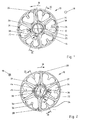
- FIGS. 1 to 4 show a ring knife 10 of a cutting set of a food crusher, for example a meat grinder, which rotates about an axis 12.
- the knife is driven by a shaft, not shown, which cooperates positively with the central two-edged opening 14.
- the knife rotates in operation in the direction of arrow 16.
- Fig. 1 shows the plan view of the downstream side of the knife
- Fig. 2 a plan view of the inflow side shows.
- the flow direction of the material to be shredded is accordingly indicated by the symbols 18.
- meat is the material to be shredded.
- meat is always referred to as material to be comminuted, without this being to be understood as limiting.
- full blade bars 22 extend outwardly.
- six such Vollmesserbalken 22 are provided, of which for clarity, only a part is provided with reference numeral.
- the embodiment shows six equally spaced solid knife bars 22. Other numbers are also possible, for example three, four or more.
- the full blade bars 22 terminate at an outer ring 24, which may for example have an outer diameter of 15 to 20 cm.
- the thickness of the knife body in the direction of flow is, for example, one to a few centimeters.
- the full blade bars 22 comprise on the downstream side of the blade 10, which in Fig. 1 visible, knife blades 26, of which in turn only a few are provided with reference numerals. They serve to separate the meat which has passed through the openings 34 of the knife 10.
- knife blades 26 of which in turn only a few are provided with reference numerals. They serve to separate the meat which has passed through the openings 34 of the knife 10.
- the in Fig. 2 is shown, the Vollmesserbalken 22 knife blades 28, of which also only a few are provided with reference numerals.
- Both the knife blades 26 on the downstream side of the blade 10, and the knife blades 28 on the upstream side of the blade 10 are not exactly aligned radially. Instead, the inner end of the knife blades 26, 28 (and thus also the knife edges) precede the outer end, which is farther from the hub 20, in the direction of rotation 16 of the rotating knife 10, thereby achieving good shearing of the meat.
- the orientation of the cutting is chosen the other way around, so in particular the ends of the knife blades close to the hub run after the ends remote from the hub in the direction of movement of the rotating blade. Such an embodiment ensures that the meat moves in the openings towards the center.
- FIG. 4 The cross section of a metering bar 22 is in Fig. 4 shown.
- Fig. 1 and 2 is the line of sight of Fig. 4 shown on this cross section with IV-IV.
- Fig. 4 the flow direction of the meat is again denoted by 18.
- the line of sight in Fig. 1 is visible in is Fig. 4 denoted by I.
- the line of sight in Fig. 2 is visible in is Fig. 4 denoted by II.
- Arrow 16 again indicates the direction of movement of the cutter bar 22 when the knife 10 is rotating.
- Fig. 4 recognizable that on the trailing in the direction of rotation 16 of the knife side of the Vollmesserbens 22 bevel 30 is provided, which causes the Vollmesserbalken 22 on the upstream side of the blade 10 is wider than on the downstream side.
- the support cross-sectional width 46 of a full-diameter bar 22 is thus greater on the inflow side than the support cross-sectional width 48 on the outflow side.
- the chamfers 30 are also in Fig. 1 visible, and here they are provided for clarity only in some of the Vollmesserbalken 22 with reference numerals.
- the chamfers 30 extend in this embodiment along the entire length of the respective Vollmesserbalkens 22 and along the outer ring 24th
- chamfer 30 is provided, but, for example, a concave shape, which is designed such that the Vollmesserbalken are wider on the upstream side than on the downstream side.
- a concave shape is in Fig. 5 wherein reference numeral 32 denotes the concave, in the direction of rotation 16 of the rotating blade 10 trailing surface of the Vollmesserbalkens 22.
- Two adjacent solid blade bars 22 and outer ring 24 each form openings 34 in the blade which act as individual pressure chambers.
- the bevels 30 and the concave surfaces 32 ensure that the openings 34 expand in the direction of flow 18.
- the achievable by reducing the width of the Vollmesserbalken 22 Extension of the openings 34 in the direction of flow 18 of the meat can be, for example, 30% of the opening size of the openings 34.
- these cutter blades 36 carry knife blades 38, which point in the direction of the hub 20.
- these knife edges are not exactly aligned radially. Instead, they are arranged obliquely so that the ends of the knife blades close to the ends run ahead of the ends in the direction of movement 16 of the rotating blade 10, whereby a good shearing off of the meat is achieved.
- the orientation of the cutting is chosen the other way around, so in particular the ends of the knife blades close to the hub run after the ends remote from the hub in the direction of movement of the rotating blade.
- exactly one partial knife bar 36 is arranged between each two solid cutter bars 22.
- two or more metering blades 36 are provided with corresponding cutter blades 38 between two Vollmesserbalken 22.
- Still other embodiments provide that not in all openings 34 between two Vollmesserbalken 22 one or more Operamesserbalken 36 are provided.
- Fig. 3 shows a section through the knife 10, the direction of view of this section in the Fig. 1 and 2 marked with III-III.
- the flow direction of the meat is again indicated by the arrow 18.
- the direction II one looks at the blade surface 40 of the upstream side of the blade 10.
- the blade surface 40 corresponds to the blade plane which is formed by the cutting edges of the blade blades 28 of the full blade 22 on the inflow side.
- the described embodiment of the knife 10 according to the invention acts as follows.
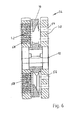
- FIG Fig. 6 An exemplary cutting set 54 with a knife 10 is shown in FIG Fig. 6 shown.
- the knife 10 rotates in this embodiment about the axis 12 between two fixed perforated discs 50 and 52nd
- the first perforated disc 50 which at the in Fig. 2 visible upstream side of the blade 10 has, in comparison to the second perforated disc 52, which at the in Fig. 1 visible downstream side of the blade 10 is arranged, larger holes 56 in a correspondingly smaller number per area.
- the second perforated disk 52 is therefore also referred to as a fine perforated disk and the first perforated disk 50 as a rough perforated disk.
- the pinhole disk 52 has twenty-two to fifty holes 58, and the rough hole disk 50 has three to seven holes 56.
- the holes 56 in the rough hole disk 50 and the holes 58 in the pinhole disk 52 are shown in FIG Fig. 6 only partially provided with reference numbers.
- the meat enters the openings 34 of the rotating blade 10 through the holes 56 of the roughing hole 50 located on the upstream side of the blade 10.
- the knife blades 28 on the upstream side of the blade 10 separate the meat that collects in the openings 34.
- the entry of the meat into the openings 34 is not substantially hindered by the metering blades 36, since these are at least partially set back on the upstream side of the blade 10, as shown in FIG Fig. 3 is visible.
- the meat entered into the openings 34 is pressed onto the fine perforated disk 52, which adjoins the rotating blade 10 in the cutting set in the direction of flow 18 and is likewise generally stationary.
- This fine perforated disc 52 has more and smaller holes 58 than the rough perforated disc 50. Because the solid carbide blades 22 on the downstream side of the blade 10 have a smaller span width as on the upstream side, it is ensured that the meat located in an opening 34 can hit a larger number of holes 58 in the fine perforated disk 52 than if the solid blade bars 22 had a constant width in the throughflow direction 18.
- the meat which enters through the openings 34 in the holes 58 of the subsequent fine perforated disc 52 is separated in particular by the knife blades 26 on the full blade bar 22.
- a separation is effected in particular in the radially outer region of the blade 10 by the blades 38 on the metering blade 36. In this way, the increased discharge performance is taken into account by the increasing cross sections of the openings 34.
- the described embodiment of the knife of a cutting set of a food shredder combines several advantages.
- By reducing the width of the Vollmesserbalken 22 in the direction of flow 18 of the meat through the chamfers 30 ensures that on the downstream side of the knife 10 a larger area and thus a larger number of holes 58 of the subsequent fine perforated disc 52 is acted upon by the meat than in a conventional Knife.
- the reduction in the width of the solid blade bars 22 is not detrimental to the stability of the blade as there are only about 25% of the rotational forces on the downstream side as compared to about 75% of the rotational forces occurring on the upstream side. On the thus far more loaded upstream side of the Vollmesserbalken 22 are wider.
- the entry of the meat into the openings 34 is not or not substantially hindered. Nevertheless, it will open the outflow side of the blade 10 by the Operamesserbalken 36 with the blades 38 reaches a high cutting performance, so that the guaranteed by the enlargement of the openings 34 performance increase can be processed and cut well especially on the downstream side.
Description
Die Erfindung betrifft ein Ringmesser für mehrteilige, aus stationären Lochscheiben und zumindest einem rotierenden Messer bestehende Schneidsätze von Zerkleinerungsmaschinen, insbesondere für Fleischwölfe und dergleichen, umfassend einen eine Zuströmseite und eine Abströmseite aufweisenden Messerkörper mit einer Nabe und einem Außenring sowie mehreren sich zwischen Nabe und Außenring erstreckenden, Messerklingen tragenden Vollmesserbalken, die zusammen mit dem Außenring und der Messernabe Messerräume begrenzen, sowie ebenfalls Messerklingen tragenden Teilmesserbalken, die sich ausgehend vom Außenring in die Messerräume erstrecken. Ferner ist die Erfindung auf Zerkleinerungsmaschinen mit derartigen Ringmessern gerichtet.The invention relates to a ring knife for multi-part, consisting of stationary perforated discs and at least one rotary knife cutting sets of crushing machines, especially for meat grinders and the like, comprising an inlet side and an outflow side having knife body with a hub and an outer ring and a plurality extending between the hub and outer ring Knife blades carrying knife blades which, together with the outer ring and the knife hub, limit knife spaces, as well as cutter blades carrying knife blades which extend from the outer ring into the knife spaces. Furthermore, the invention is directed to crushers with such ring knives.
Aus der
Aus der
Bei Zerkleinerungsvorrichtungen mit Schneidsätzen aus Messern und Lochscheiben läuft der Vorgang der Zerkleinerung zumindest in zwei Phasen ab.In the case of comminution devices with cutting sets of knives and perforated disks, the comminution process takes place at least in two phases.
In einer Grobzerkleinerungsphase nimmt die erste Lochscheibe ("Eintrittslochscheibe" oder "Groblochscheibe") mit vergleichsweise großen Öffnungen den jeweiligen Rohstoff in großstückiger, mechanisch kompakter Form auf und es wird an der austritts- bzw. abströmseitigen Seite der Lochscheibe mit den dieser Seite zugewandten Messerklingen mittels Scherwirkung eine Grobzerkleinerung des Rohstoffes vorgenommen. Der Schervorgang wird durch das Zusammenwirken der Messerklingen mit den Kanten der Lochscheibenbohrungen bewirkt. Bei diesem Vorgang treten infolge der stofflichen Kompaktheit des Rohstoffes große Kräfte auf, so dass die Messer bzw. Messerträger in diesem Bereich sehr stark dimensioniert werden müssen.In a coarse comminution phase takes the first perforated disc ("entrance hole disc" or "rough perforated disc") with comparatively large openings the respective raw material in a large, mechanically compact form and it is at the exit or downstream side of the perforated disc with the side facing knife blades means Shear action made a coarse crushing of the raw material. The shearing action is caused by the interaction of the knife blades with the edges of the perforated disc bores. In this process occur due to the material compactness of the raw material on large forces, so that the knives or knife carrier in this area must be very strongly dimensioned.
Die erwähnte Zerkleinerungsphase hat zur Folge, dass sich die stoffliche, mechanische Festigkeit durch kleinere Stückigkeit erheblich reduziert und die Rohstoffteilgröße besser in nachfolgende kleinere Lochscheibenbohrungen eindringen lässt. Diese kleineren Bohrungen sind in der in Durchflussrichtung auf das Messer folgenden nächsten Lochscheibe ausgebildet. Demgemäß befindet sich das Messer zwischen einer Groblochscheibe und einer Feinlochscheibe, wobei das Messer bevorzugt als Ringmesser ausgebildet ist und zwischen den im Wesentlichen radial verlaufenden Messerbalken des Ringmessers beidseitig durch die Lochscheibe begrenzte Messerräume vorliegen.The mentioned comminution phase has the consequence that the material, mechanical strength is considerably reduced by smaller pieces and the raw material part size can penetrate better into subsequent smaller perforated disc bores. These smaller holes are formed in the next perforated disc following in the flow direction on the blade. Accordingly, the knife is located between a rough perforated disc and a fine perforated disc, wherein the knife is preferably designed as a ring knife and present between the substantially radially extending cutter bar of the ring diameter on both sides limited by the perforated disc cutter chambers.
Für die Funktion ist wesentlich, dass in die Bohrungen der Feinlochscheibe eindringender Rohstoff die Feinlochscheibe nur dann auch wieder verlassen kann, wenn er direkt nach dem Eindringen in die entsprechende Bohrung durch die Scherwirkung der Messerklingen an der messerseitigen Bohrungskante durchtrennt wird. Steht für diesen erforderlichen Trennvorgang gleich nach Eindringen des Rohstoffs in die entsprechende Bohrung der Feinlochscheibe keine Klinge zur Verfügung, wird der in die Lochscheibenbohrung eindringende Rohstoff wieder aus der Bohrung herausgeschoben, d.h. es kann nicht gleichmäßig über die gesamte Lochscheibenfläche geschnitten werden, da der Abstand der aufeinanderfolgend wirksam werdenden Messerklingen für die Bohrungsanordnung bei gegebener Rotationsbewegung des Messers zu groß ist. Damit kann bei Standardmessern die Schneidleistung ohne weiteres um bis zu 60% sinken.It is essential for the function that raw material penetrating into the holes of the fine perforated disk can only leave the fine perforated disk again if it is severed directly after penetration into the corresponding bore by the shearing action of the knife blades on the knife-side bore edge. If there is no blade available for this required separation process immediately after penetration of the raw material into the corresponding bore of the fine perforated disc, the raw material penetrating into the perforated disc bore is again pushed out of the bore, ie it can not be cut uniformly over the entire perforated disc surface, since the distance between the Successively effective knife blades for the hole assembly is given at a given rotational movement of the knife is too large. With standard knives, the cutting performance can easily be reduced by up to 60%.
Des Weiteren gilt für alle Lochscheiben, dass jede Bohrungsöffnung ein Einzelschneidwerkzeug darstellt und diese Einzelschneidwerkzeuge nur dann arbeiten können, wenn die Öffnungen bzw. Bohrungen in den Lochscheiben unverdeckt von den die Messerklingen tragenden Messerbalken zur Verfügung stehen. Wenn somit durch die Messerbalken Teilbereiche der Lochscheibe abgedeckt sind, kann das zu verarbeitende Material durch den anliegenden Schubdruck nicht gleichzeitig in alle Bohrungen eindringen, wodurch die Lochscheibenleistung sinkt. Herkömmlich gestaltete Messerkörper verdecken häufig 30% bis 40% der Lochscheibenöffnungen und verringern damit die Anzahl der wirksamen Schneidwerkzeuge der Lochscheibe. Diese nachteiligen Effekte sind besonders bei Feinlochscheiben evident, da hier die Anzahl der Bohrungen besonders groß ist.Furthermore, for all perforated disks, each hole opening represents a single cutting tool and these individual cutting tools can only work if the openings or holes in the perforated disks are unobstructed by the cutter blades carrying the knife blades available. Thus, if portions of the perforated disc are covered by the cutter bar, the material to be processed can not simultaneously penetrate into all holes due to the applied thrust pressure, as a result of which the perforated disc power decreases. Conventionally designed knife bodies often obscure 30% to 40% of the perforated disc openings and thus reduce the number of effective cutting tools of the perforated disc. These adverse effects are particularly evident in fine perforated discs, since here the number of holes is particularly large.
Da in der bereits erwähnten Weise in der Grobzerkleinerungsphase sehr hohe Kräfte auftreten, sind die bekannten Standardmesser für mechanische Höchstbelastung ausgelegt und demgemäß die die Messerklingen tragenden Messerbalken entsprechend groß dimensioniert, was zur Folge hat, dass sich in Förderrichtung des Rohstoffes unerwünscht große Anströmwiderstände ergeben und diese räumlich großen Messerbalken durch ihre Fläche einen Großteil der Lochscheibenfläche bzw. der Einzelschneidwerkzeuge bildenden Bohrungen der Lochscheibe verdecken. Dies hat zur Folge, dass die Leistung derartiger Schneidsätze nicht zufriedenstellend ist, weil der zerkleinerte Rohstoff in den Bohrungen der zweiten Lochscheibe bzw. Feinlochscheibe nicht schnell genug mit dem zeitlich notwendigen Trennschnitt abgeschnitten werden kann, da der Bewegungsweg vom Messer zur jeweiligen Bohrung zu groß ist.Since very high forces occur in the coarse comminution phase in the already mentioned manner, the known standard knives are designed for maximum mechanical load and accordingly the knife blades carrying the cutter bar correspondingly large, which has the consequence that in the conveying direction of the raw material undesirably large flow resistance arise and this spatially large cutter bar cover by their surface a large part of the perforated disc surface or the individual cutting tools forming holes of the perforated disc. This has the consequence that the performance of such cutting sets is not satisfactory, because the crushed raw material in the holes of the second perforated disc or fine perforated disc can not be cut fast enough with the time-required separating cut, since the path of movement from the knife to the respective hole is too large ,
Aufgabe der Erfindung ist es daher insbesondere, ein Ringmesser der eingangs angegebenen Art so auszugestalten, dass den unterschiedlichen mechanischen Beanspruchungen der aufeinander folgenden Schneidfolgen bei erfolgter Änderung des mechanischen Rohstoffzustandes Rechnung getragen werden kann und die Leistungsfähigkeit der Schneidsätze ganz wesentlich gesteigert wird.The object of the invention is therefore in particular, a ring cutter of the type described in such a way that the different mechanical stresses of the successive cutting sequences can be taken into account when the mechanical state of the raw material has changed, and the efficiency of the cutting sets is substantially increased.
Diese Aufgabe wird mit einem Ringmesser mit den Merkmalen des Anspruches 1 bzw. einer Vorrichtung zum Zerkleinern von Lebensmitteln mit den Merkmalen des Anspruches 8 gelöst.This object is achieved with a ring knife with the features of
Gelöst wird diese Aufgabe nach der Erfindung also im Wesentlichen dadurch, dass die Anzahl der abströmseitig gelegenen wirksamen Messerklingen größer als die Anzahl der zuströmseitig gelegenen wirksamen Messerklingen ist, und dass sich die Messerräume in Richtung der Durchströmung des Messerkörpers erweitern.This object is achieved according to the invention, therefore, essentially by the fact that the number of effector blades located downstream is greater than the number of effective knife blades located on the inflow side, and that the blade chambers expand in the direction of the flow through the blade body.
Der Begriff "zuströmseitig" wird dabei für die Messerseite benutzt, die in Durchströmrichtung des zu zerkleinernden Materials stromaufwärtig angeordnet ist. Die "Abströmseite" entspricht der Seite des Messerkörpers, die in Richtung der Durchströmung stromabwärtig angeordnet ist. Die "Richtung der Durchströmung" wird durch die Richtung definiert, in der sich das zu zerkleinernde Material beim Zerkleinerungsvorgang durch die Messerräume des Messerkörpers bewegt. Der Begriff "Klinge" wird im vorliegenden Text für diejenigen Elemente des Messers verwendet, die Schneidkanten aufweisen.The term "inflow side" is used for the knife side, which is arranged upstream in the flow direction of the material to be crushed. The "outflow side" corresponds to the side of the knife body, which is arranged downstream in the direction of the flow. The "direction of the flow" is defined by the direction in which moves the material to be crushed in the crushing process through the knife chambers of the knife body. The term "blade" is used herein to refer to those elements of the blade having cutting edges.
Durch die erfindungsgemäße Gestaltung der Messerräume wird unter anderem erreicht, dass den Kräftebeanspruchungen des Ringmessers praktisch gesondert nach Grobschnitt, d.h. großer Belastung, und Feinschnitt, d.h. geringerer Belastung, Rechnung getragen wird. Durch die erhöhte Anzahl der abströmseitig gelegenen Messerklingen im Vergleich zur Zuströmseite wird erreicht, dass die vorteilhaft hohen Schnittfolgen erzielt werden, so dass eine optimale Eindringgeschwindigkeit des Rohstoffes in die Bohrungen gewährleistet und das Material auch wieder aus den Bohrungen abgeführt werden kann.The design of the knife chambers according to the invention achieves, inter alia, that the forces acting on the ring knife are taken into account practically separately according to the rough section, ie, a large load, and a fine cut, ie, a lower load. Due to the increased number of downstream knife blades in comparison to the inflow side it is achieved that the advantageously high cutting sequences are achieved, so that an optimum penetration rate of the raw material into the holes ensures and the material can be removed again from the holes.
Des Weiteren ist von Bedeutung, dass durch die in Durchströmrichtung vorgenommene Erweiterung der Messerräume mit einem ausgesprochen geringen Verdeckungsgrad der Lochscheibenbohrungen gearbeitet werden kann, d.h. es ist die größtmögliche Anzahl von Einzelwerkzeugen der Lochscheibe, d.h. Bohrungskanten wirksam. Diese erhöhte Lochscheibenarbeitsfläche auf der der Abströmseite des Ringmessers in Durchströmrichtung nachfolgenden Feinlochscheibe erfordert mehr Schnitte in kürzerer Zeit, und dies wird durch die größer gewählte Anzahl der abströmseitig gelegenen wirksamen Messerklingen gewährleistet. Es wird somit eine besonders hohe Zerkleinerungsleistung durch wirksame Trennarbeit von Rohstoff, Bohrungskanten und Messerklingen zeitbezogen erzielt.Furthermore, it is important that can be worked by the extension made in the flow direction of the knife chambers with a very low degree of concealment of perforated disc bores, i. it is the largest possible number of individual tools of the perforated disc, i. Bore edges effective. This increased perforated disc working surface on the downstream of the ring diameter in the flow direction subsequent fine perforated disc requires more cuts in a shorter time, and this is ensured by the larger selected number of downstream effective knife blades. It is thus achieved a particularly high crushing performance by effective separation work of raw material, hole edges and knife blades time related.
Bevorzugt weisen die Vollmesserbalken ausgehend von einem zuströmseitigen Größtmaß ihres Querschnitts einen zur Abströmseite hin sich verringernden Querschnitt auf. Auf diese Weise lässt sich der Tatsache Rechnung tragen, dass für den Grobschnitt etwa 75% der Motorkraft und für den Feinschnitt nur etwa 25% der Motorkraft des das Ringmesser antreibenden Motors benötigt wird. Die Vollmesserbalken können demgemäß auf der höher belasteten Seite etwa den dreifachen Materialquerschnitt im Vergleich zum Materialquerschnitt auf der Feinschnittseite haben. Da die Vollmesserbalken zur Feinlochscheibe hin gerichtet demgemäß einen sich verringernden Querschnitt besitzen, d.h. keilförmig gestaltet werden können, wird auf der Feinlochscheibenseite entsprechende Lochscheibenwirkfläche frei.Starting from an inflow-side maximum dimension of their cross-section, the solid-diameter bars preferably have a cross-section which reduces toward the outflow side. In this way, account can be taken of the fact that for the rough cut about 75% of the engine power and for the fine cut only about 25% of the engine power of the ring knife driving motor is needed. The Vollmesserbalken can accordingly have on the higher loaded side about three times the material cross section compared to the material cross section on the fine cut side. Since the Vollmesserbalken to the fine perforated disc directed towards accordingly have a decreasing cross-section, ie can be wedge-shaped, corresponding Lochscheibewirkfläche is free on the Feinlochscheibenseite.
Während für die Grobschnittseite gilt, dass aufgrund der langsameren Eindringzeit der groben Rohstoffstücke in die Bohrungen der Lochscheibe ein verhältnismäßig großer Abstand zwischen aufeinander folgenden Vollmesserbalken freigehalten werden muss, sind auf der Feinlochscheibenseite zusätzliche Messerklingen erforderlich, um sicherzustellen, dass bei der höheren Anzahl von Bohrungen in der Feinlochscheibe und im Hinblick auf den schneller fließenden Rohstoff die zeitlich richtigen Trennschnitte an der Lochscheibenoberfläche durchgeführt werden können. Diese zeitlich richtigen Trennschnitte können durch die abströmseitig größere Anzahl von wirksamen Messerklingen erreicht werden, die an den Teilmesserbalken vorgesehen sind. Erst durch diese höhere Anzahl von Messerklingen an den sich vom Außenring nach innen erstreckenden Teilmesserbalken, die mit der Feinlochscheibe zusammenarbeiten, werden die physikalischen Abläufe der Rohstoffbearbeitung, bestehend aus dem Eindring- und Abschneidezyklus, optimal erfüllt.While for the coarse cut side, due to the slower penetration of the coarse pieces of raw material into the holes of the orifice plate, a relatively large gap must be kept between consecutive knife blades, additional knife blades are required on the fine orifice plate side to ensure that with the higher number of holes in the fine perforated disc and in view of the faster flowing raw material the timely separating cuts can be performed on the perforated disc surface. These timely separating cuts can be achieved by the downstream larger number of effective knife blades, which are provided on the Teilmesserbalken. Only by this higher number of knife blades on the outer ring extending inwardly Teilmesserbalken that work together with the fine perforated disc, the physical processes of raw material processing, consisting of the penetration and Abschneidezyklus, optimally met.
Von besonderem Vorteil ist dabei, wenn die Teilmesserbalken zumindest zum Teil ausgehend vom Außenring über ihre Länge einen abnehmenden Querschnitt aufweisen, wobei die zuströmseitigen Begrenzungsflächen dieser Teilmesserbalken bezüglich der von den Schneidkanten der Messerklingen auf der Zuströmseite gebildeten zuströmseitigen Messerebene beabstandet und insbesondere vom Außenring nach innen zunehmend beabstandet sind.It is particularly advantageous if the Teilmesserbalken at least partially starting from the outer ring over its length have a decreasing cross-section, wherein the inflow-side boundary surfaces of these Teilmesserbalken spaced with respect to the formed by the cutting edges of the knife blades on the inflow side inflecting knife plane and in particular increasingly from the outer ring to the inside are spaced.
Dies trägt auch wesentlich zur Vergrößerung der Messerräume des Messerkörpers sowie dazu bei, dass im Durchfluss praktisch kein Störkörper vorhanden ist.This also contributes significantly to the enlargement of the knife chambers of the knife body as well as to the fact that practically no obstruction exists in the flow.
Die für die Erfindung wesentliche Erweiterung der Messerräume in Durchströmrichtung des Messerkörpers wird bevorzugt durch entsprechende Wandungsschrägen von Vollmesserbalken und/oder Teilmesserbalken und/oder Außenring und/oder Nabe erreicht. Bevorzugt werden alle diese Maßnahmen gleichzeitig genutzt.The essential for the invention extension of the knife chambers in the flow direction of the knife body is preferably by appropriate Wandungsschrägen of solid blade and / or knife blade and / or outer ring and / or hub reached. Preferably, all these measures are used simultaneously.
Zwischen zwei nebeneinander liegenden Vollmesserbalken mit zugehörigen Messerklingen kann mehr als ein Teilmesserbalken mit zugehöriger Messerklinge vorgesehen sein, da im Außenbereich der Lochscheibe, in dem die Messerklingen der Teilmesserbalken wirksam sind, etwa 80% aller Bohrungen gelegen sind. Es wird dabei stets angestrebt, dass jeweils die gleiche Anzahl an Messerklingen je Bohrung auf der räumlichen Fläche für die Schnittausführung zur Verfügung gestellt werden kann. Die Anzahl der Schneiden der Vollmesserbalken und der Schneiden der Teilmesserbalken wird mit den Bohrungsgrößen, den Stoffzustandsformen und dem zeitlich druckbezogenen Eindringverhalten des Rohstoffes in die Bohrungen mit den Maschinenparametern abgestimmt. Das ist schon deshalb vorteilhaft, weil der Gesamtvorgang bei Messerdrehzahlen von 200 bis 400 Umdrehungen pro Minute abläuft. Da der Rohstoff in einem Messerraum unter Schubdruck steht und immer zum gleichen Zeitpunkt vollständig in alle Bohrungen der Lochscheibe eindringt, muss der gleichzeitige Scher- bzw. Trennschnitt mit allen Messerklingen auf der Lochscheibe zumindest im Wesentlichen gesichert sein. Auf diese Weise kann die Messer- und Lochscheibenleistung im Vergleich zur bekannten Anordnung ohne weiteres um 80% und sogar bis zu 100% erhöht werden.Between two juxtaposed solid knife bars with associated knife blades more than one Teilmesserbalken with associated knife blade can be provided, as in the outer area of the perforated disc in which the knife blades of the cutter bars are effective, about 80% of all holes are located. It is always desirable that each of the same number of knife blades per hole on the spatial surface for cutting execution can be provided. The number of cutting edges of the cutter bars and the cutting edges of the cutter bars is matched with the bore sizes, the material state shapes and the time pressure-related penetration behavior of the raw material into the holes with the machine parameters. This is advantageous because the entire process takes place at knife speeds of 200 to 400 revolutions per minute. Since the raw material is under shear pressure in a knife chamber and always penetrates completely into all holes of the perforated disc at the same time, the simultaneous shearing or separating cut must be at least substantially secured with all knife blades on the perforated disc. In this way, the knife and orifice plate performance compared to the known arrangement can be easily increased by 80% and even up to 100%.
Diese vorteilhaften Effekte und Ergebnisse werden auf der so genannten Grobseite - also der Zuströmseite des Messers - vor allem erreicht durch eine gute Rohstoffaufnahme aufgrund großer Abstände zwischen den Kraft übertragenden Vollmesserbalken sowie durch die in Durchströmrichtung zurückgesetzten Teilmesserbalken zum Zwecke der Beseitigung von Störungen beim Eindringen des Rohstoffs in den jeweiligen Messerraum.These advantageous effects and results are achieved on the so-called coarse side - ie the upstream side of the blade - especially by a good raw material intake due to large distances between the force-transferring Vollmesserbalken and by the back in the flow direction Teilmesserbalken for the purpose of eliminating disturbances in the penetration of the raw material in the respective knife room.
Auf der so genannten Feinseite - also der Abströmseite des Messers - wirkt sich die Erhöhung der Anzahl von Messerklingen zur Erzeugung kürzerer Schneidzyklen und die Verringerung des Querschnitts der Messerbalken in Durchströmrichtung zur Vergrößerung der Arbeitsfläche auf der Feinlochscheibe vorteilhaft aus.On the so-called fine side - ie the outflow side of the knife - the increase in the number of knife blades to produce shorter cutting cycles and the reduction of the cross section of the cutter bar in the direction of flow to increase the working surface on the fine perforated disc advantageous.
Neben dem vorstehend beschriebenen Ringmesser umfasst die Erfindung auch eine Vorrichtung zum Zerkleinern von Lebensmitteln, insbesondere zum Zerkleinern von Fleisch und dergleichen, mit mindestens einem Lochscheiben-Ringmesser-Schneidsatz, bei dem der Zuströmseite zumindest einer Lochscheibe ein Ringmesser der beschriebenen Art mit seiner Abströmseite zugeordnet ist.In addition to the ring knife described above, the invention also includes a device for mincing food, in particular for mincing meat and the like, with at least one perforated disc ring cutter set, in which the inflow side of at least one perforated disc is assigned a ring knife of the type described with its downstream side ,
Weitere vorteilhafte Ausführungsformen und Merkmale der Erfindung sind in den Unteransprüchen angegeben und werden auch in der nachfolgenden Beschreibung von Ausführungsbeispielen erläutert.Further advantageous embodiments and features of the invention are specified in the subclaims and are also explained in the following description of exemplary embodiments.
Die Erfindung wird anhand der anliegenden Figuren im Detail erläutert, die eine Ausführungsform eines erfindungsgemäßen Ringmessers darstellen. Dabei zeigen
- Fig. 1
- eine Draufsicht auf die Abströmseite einer Ausführungsform eines erfindungsgemäßen Ringmessers,
- Fig. 2
- eine Draufsicht auf die Zuströmseite dieses Messers,
- Fig. 3
- eine Schnittzeichnung des Messers, wobei die Schnittebene in
Fig. 1 und inFig. 2 mit III-III angegeben ist, - Fig. 4
- eine Schnittzeichnung durch einen Teil des Messers, wobei die Schnittebene in
Fig. 1 und inFig. 2 mit IV-IV angegeben ist, - Fig. 5
- einen alternativen Querschnitt eines Vollmesserbalkens, und
- Fig. 6
- eine schematische Seitenansicht eines beispielhaften Schneidsatzes eines Fleischwolfes.
- Fig. 1
- a plan view of the downstream side of an embodiment of a ring knife according to the invention,
- Fig. 2
- a plan view of the upstream side of this knife,
- Fig. 3
- a sectional drawing of the knife, wherein the cutting plane in
Fig. 1 and inFig. 2 indicated with III-III, - Fig. 4
- a sectional view through a part of the knife, wherein the cutting plane in
Fig. 1 and inFig. 2 with IV-IV, - Fig. 5
- an alternative cross section of a Vollmesserbalkens, and
- Fig. 6
- a schematic side view of an exemplary cutting set of a meat grinder.
Die
Von der Nabe 20 erstrecken sich Vollmesserbalken 22 nach außen. Bei der gezeigten Ausführungsform sind sechs derartige Vollmesserbalken 22 vorgesehen, von denen der Übersichtlichkeit halber nur ein Teil mit Bezugsziffer versehen ist. Die Ausführungsform zeigt sechs gleich beabstandete Vollmesserbalken 22. Andere Anzahlen sind ebenfalls möglich, zum Beispiel drei, vier oder mehr.From the
Die Vollmesserbalken 22 enden an einem Außenring 24, der zum Beispiel einen Außendurchmesser von 15 bis 20 cm haben kann. Die Dicke des Messerkörpers in Durchströmrichtung beträgt zum Beispiel ein bis einige Zentimeter.The full blade bars 22 terminate at an
Die Vollmesserbalken 22 umfassen auf der Abströmseite des Messers 10, die in
Sowohl die Messerklingen 26 auf der Abströmseite des Messers 10, als auch die Messerklingen 28 auf der Zuströmseite des Messers 10 sind nicht genau radial ausgerichtet. Stattdessen läuft das innere Ende der Messerklingen 26, 28 (und insofern auch die Messerschneiden) dem äußeren Ende, das weiter entfernt von der Nabe 20 ist, in Drehrichtung 16 des rotierenden Messers 10 voraus, wodurch ein gutes Abscheren beziehungsweise Abtrennen des Fleisches erreicht wird. Bei manchen Rohstoffen kann es aber auch sinnvoll sein, wenn die Ausrichtung der Schneiden anders herum gewählt ist, also insbesondere die nabennahen Enden der Messerschneiden den nabenfernen Enden in Bewegungsrichtung des rotierenden Messers nachlaufen. Eine solche Ausführungsform gewährleistet, dass sich das Fleisch in den Öffnungen zur Mitte hin bewegt.Both the
Der Querschnitt eines Vollmesserbalkens 22 ist in
Insbesondere ist in
Die Anschrägungen 30 sind auch in
Alternative Ausführungsformen sehen vor, dass keine Anschrägung 30 vorgesehen ist, sondern zum Beispiel eine konkave Form, die derart ausgebildet ist, dass die Vollmesserbalken auf der Zuströmseite breiter sind als auf der Abströmseite. Eine solche mögliche Querschnittsform ist in
Zwei benachbarte Vollmesserbalken 22 und der Außenring 24 bilden jeweils Öffnungen 34 in dem Messer, die wie individuelle Druckräume wirken. Durch die Anschrägungen 30 bzw. die konkaven Flächen 32 ist sichergestellt, dass sich die Öffnungen 34 in Durchströmrichtung 18 erweitern. Die durch die Verringerung der Breite der Vollmesserbalken 22 erreichbare Erweiterung der Öffnungen 34 in Durchströmrichtung 18 des Fleisches kann zum Beispiel 30 % der Öffnungsgröße der Öffnungen 34 betragen.Two adjacent solid blade bars 22 and
Zwischen zwei benachbarten Vollmesserbalken 22 erstrecken sich ausgehend vom Außenring 24 Teilmesserbalken 36 in Richtung der Nabe 20 nach innen, von denen in den
Auf der Abströmseite des Messers 10, die in
Bei der gezeigten Ausführungsform ist zwischen je zwei Vollmesserbalken 22 genau ein Teilmesserbalken 36 angeordnet. Bei anderen, nicht gezeigten Ausführungsformen sind zwischen zwei Vollmesserbalken 22 zwei oder mehr Teilmesserbalken 36 mit entsprechenden Messerklingen 38 vorgesehen. Wiederum andere Ausführungsformen sehen vor, dass nicht in allen Öffnungen 34 zwischen zwei Vollmesserbalken 22 ein oder mehrere Teilmesserbalken 36 vorgesehen sind.In the embodiment shown, exactly one
Die Blickrichtung auf die Abströmseite, die in
In der Schnittansicht der
An den Teilmesserbalken 36 sind nur auf der Abströmseite des Messers 10, die in
Die geschilderte Ausführungsform des erfindungsgemäßen Messers 10 wirkt wie folgt.The described embodiment of the
Ein beispielhafter Schneidsatz 54 mit einem Messer 10 ist in
Die erste Lochscheibe 50, die an der in
Das Fleisch tritt durch die Löcher 56 der auf der Zuströmseite des Messers 10 angeordneten Groblochscheibe 50 in die Öffnungen 34 des rotierenden Messers 10 ein. Die Messerklingen 28 auf der Zuströmseite des Messers 10 trennen das Fleisch ab, das sich in den Öffnungen 34 sammelt. Der Eintritt des Fleisches in die Öffnungen 34 wird durch die Teilmesserbalken 36 nicht wesentlich behindert, da diese zumindest teilweise auf der Zuströmseite des Messers 10 zurückversetzt sind, wie es in
Das in die Öffnungen 34 eingetretene Fleisch wird auf die Feinlochscheibe 52 gedrückt, die sich in dem Schneidsatz in Durchströmrichtung 18 an das rotierende Messer 10 anschließt und ebenfalls in der Regel feststeht. Diese Feinlochscheibe 52 hat mehr und kleinere Löcher 58 als die Groblochscheibe 50. Dadurch, dass die Vollmesserbalken 22 auf der Abströmseite des Messers 10 eine geringere Stützquerschnittsbreite haben als auf der Zuströmseite, ist sichergestellt, dass das in einer Öffnung 34 befindliche Fleisch eine größere Anzahl Löcher 58 in der Feinlochscheibe 52 treffen kann, als wenn die Vollmesserbalken 22 in Durchströmrichtung 18 konstante Breite hätten.The meat entered into the
Das Fleisch, das durch die Öffnungen 34 in die Löcher 58 der nachfolgenden Feinlochscheibe 52 eintritt, wird insbesondere durch die Messerklingen 26 an den Vollmesserbalken 22 abgetrennt. Zusätzlich wird insbesondere im radial äußeren Bereich des Messers 10 durch die Klingen 38 an den Teilmesserbalken 36 eine Abtrennung bewirkt. Auf diese Weise wird der erhöhten Abführleistung durch die sich vergrößernden Querschnitte der Öffnungen 34 Rechnung getragen.The meat which enters through the
Die geschilderte Ausführungsform für das Messer eines Schneidsatzes eines Lebensmittelzerkleinerungswolfes vereint mehrere Vorteile. Durch die Verringerung der Breite der Vollmesserbalken 22 in Durchströmrichtung 18 des Fleisches durch die Anschrägungen 30 wird gewährleistet, dass auf der Abströmseite des Messers 10 eine größere Fläche und insofern eine größere Anzahl von Löchern 58 der nachfolgenden Feinlochscheibe 52 vom Fleisch beaufschlagt wird als bei einem herkömmlichen Messer. Die Verringerung der Breite der Vollmesserbalken 22 ist hinsichtlich der Stabilität des Messers nicht schädlich, da auf der Abströmseite nur etwa 25 % der Drehkräfte im Vergleich zu den etwa 75 % der Drehkräfte anliegen, die auf der Zuströmseite anfallen. Auf der insofern mehr belasteten Zuströmseite sind die Vollmesserbalken 22 jedoch breiter.The described embodiment of the knife of a cutting set of a food shredder combines several advantages. By reducing the width of the
Durch die Teilmesserbalken 36, die mit größer werdendem Abstand vom Außenring 24 in zunehmender Weise beabstandet zu der Fläche 40 des Messers 10 der Zuströmseite sind, wird der Eintritt des Fleisches in die Öffnungen 34 nicht oder nicht wesentlich behindert. Trotzdem wird auf der Abströmseite des Messers 10 durch die Teilmesserbalken 36 mit den Klingen 38 eine hohe Schneidleistung erreicht, sodass die durch die Vergrößerung der Öffnungen 34 gewährleistete Leistungssteigerung insbesondere auf der Abströmseite gut verarbeitet und geschnitten werden kann.
Claims (10)
- A ring knife (10) for multipart cutting units (54) of comminution machines, said cutting units comprising stationary breaker plates (50, 52) and at least one rotating knife (10), in particular for meat mincers and the like,
comprising a knife body having an inflow side and an outflow side and having a hub (20) and an outer ring (24) as well as a plurality of full knife bars (22) which extend between the hub (20) and the outer ring (24), which carry knife blades (26, 28) and which, together with the outer ring (24) and the hub (20), bound knife spaces (34) and also part knife bars (36) which likewise carry knife blades (38) and which extend into the knife spaces (34) starting from the outer ring (24),
characterised in that
the number of the active knife blades (26, 38) disposed at the outflow side is larger than the number of active knife blades (28) disposed at the inflow side; and
in that the knife spaces (34) expand in the direction (18) of the throughflow of the knife body (10). - A ring knife in accordance with claim 1,
characterised in that
at least some of the full knife bars (22) have a cross-section reducing towards their outflow side starting from a largest dimension (46) of their cross-section at the inflow side. - A ring knife in accordance with claim 1 or claim 2,
characterised in that
at least some of the part knife bars (36) have a cross-section reducing over their length starting from the outer ring (24). - A ring knife in accordance with claim 3,
characterised in that
the boundary surfaces of the part knife bars (36) at the inflow side are spaced apart with respect to the knife plane (40) at the inflow side formed by the cutting edges of the knife blades (28) of the full knife bars (22) at the inflow side and are in particular inwardly increasingly spaced apart from the outer ring (24). - A ring knife in accordance with any one of the claims 1 to 4,
characterised in that
the preferably conical expansion of the knife spaces (34) is formed by wall slants (30) of the full knife bars (22) or part knife bars (36) and/or by the outer ring (24) or the hub (20). - A ring knife in accordance with any one of the claims 1 to 5,
characterised in that
the full knife bars (22) and/ or the part knife bars (36) are chamfered on the side at the rear in the direction of rotation (16) of the knife. - A ring knife in accordance with any one of the claims 1 to 6,
characterised in that
the knife body comprises two part knife bodies adjacent to one another and the one part knife body carries the knife blades forming the knife plane at the inflow side and the other part knife body carries the knife blades forming the knife plane at the outflow side. - An apparatus for comminuting foods, in particular for comminuting meat and the like, having at least one breaker plate ring knife cutting unit (54),
characterised in that
the outflow side of a ring knife (10) in accordance with one or more of the claims 1 to 7 is associated with the inflow side of at least one breaker plate (52). - An apparatus in accordance with claim 8,
characterised in that
the ring knife (10) is rotatingly arranged between two stationary breaker plates (50, 52), with the breaker plate (52) at the outflow side having a larger number of holes (58) and smaller holes (58) than the breaker plate (50) at the inflow side. - An apparatus in accordance with claim 9,
characterised in that
the hole size and the number of holes of the breaker plate (52) at the outflow side and the associated number of knife blades and the number of knives are coordinated in dependence on the properties of the material to be processed such that substantially simultaneous shearing cuts take place over the total breaker plate surface.
Priority Applications (1)
| Application Number | Priority Date | Filing Date | Title |
|---|---|---|---|
| EP20100004712 EP2384817B1 (en) | 2010-05-04 | 2010-05-04 | Ring knife for cutting sets of grinding machines |
Applications Claiming Priority (1)
| Application Number | Priority Date | Filing Date | Title |
|---|---|---|---|
| EP20100004712 EP2384817B1 (en) | 2010-05-04 | 2010-05-04 | Ring knife for cutting sets of grinding machines |
Publications (2)
| Publication Number | Publication Date |
|---|---|
| EP2384817A1 EP2384817A1 (en) | 2011-11-09 |
| EP2384817B1 true EP2384817B1 (en) | 2013-07-24 |
Family
ID=42801093
Family Applications (1)
| Application Number | Title | Priority Date | Filing Date |
|---|---|---|---|
| EP20100004712 Active EP2384817B1 (en) | 2010-05-04 | 2010-05-04 | Ring knife for cutting sets of grinding machines |
Country Status (1)
| Country | Link |
|---|---|
| EP (1) | EP2384817B1 (en) |
Families Citing this family (1)
| Publication number | Priority date | Publication date | Assignee | Title |
|---|---|---|---|---|
| DE102013018785A1 (en) * | 2013-11-08 | 2015-05-13 | Inofex Fleisch-, Lebensmitteltechnik Und -Technologie Gmbh | Knife design to increase the performance of preferably working on the Wolfwirkprinzip cutting machines |
Family Cites Families (3)
| Publication number | Priority date | Publication date | Assignee | Title |
|---|---|---|---|---|
| DE1153287B (en) * | 1961-10-27 | 1963-08-22 | Kristian Isak William Jensen | Rotating cutting knife for meat wolves |
| DE3215950A1 (en) | 1982-04-29 | 1983-11-03 | Theodor Jopp KG, 8740 Bad Neustadt | Cutting assembly for passing machines |
| DE4301787C1 (en) | 1993-01-23 | 1994-08-25 | Inofex Fleisch Lebensmitteltec | Cutter for meat mincers |
-
2010
- 2010-05-04 EP EP20100004712 patent/EP2384817B1/en active Active
Also Published As
| Publication number | Publication date |
|---|---|
| EP2384817A1 (en) | 2011-11-09 |
Similar Documents
| Publication | Publication Date | Title |
|---|---|---|
| EP2987557B1 (en) | Grinding machine for grinding of a product | |
| EP2218507A2 (en) | Device for grinding dispensed products with stripping elements | |
| DE102007058127A1 (en) | Device for dissolving the composite of feedstock present in the composite | |
| WO2007000300A1 (en) | Knife mill | |
| EP3202290A1 (en) | Grinder, mill, device for preparing coffee with a mill and method of milling | |
| DE102010055786B4 (en) | Perforated disc system | |
| EP2384817B1 (en) | Ring knife for cutting sets of grinding machines | |
| DE102019108306A1 (en) | Cutting mill for cutting samples | |
| DE2943567A1 (en) | Fragmenting machine which works by tearing - has cylinder with helically set square cross=section teeth on cylindrical stubs fitted radially | |
| DE102010055785B4 (en) | Konti cutter vacuum | |
| EP2452554A1 (en) | Mechanical assembly for processing arable crops | |
| EP2311568B1 (en) | Cutting assembly with safety distance ring measurer | |
| EP3515602B1 (en) | Fine grinder | |
| EP2548648B1 (en) | Mill for comminuting of material | |
| DE10048886C2 (en) | Device for comminuting feed material with a comminuting system rotating about an axis of rotation | |
| WO2018050809A1 (en) | Chopping rotor for a comminution device, in particular a chopper | |
| AT374377B (en) | DEVICE FOR CRUSHING AGRICULTURAL GOODS | |
| DE102004012201B4 (en) | Comminution machine for breaking up metal swarf or plastics or wood chips has two rotors side-by-side with interdigitating knife blades of two different widths | |
| DE102013104587B4 (en) | Profiled comminution disc, crushing roller and shredder for harvesters | |
| DE10018005A1 (en) | Method and device for reducing splinter material to powder feeds material to be processed through an inlet in an external wall into a processing chamber for shredding by a rotor. | |
| EP1946641B1 (en) | Breaker plate with integrated cutting nut system | |
| DE102015203790B4 (en) | Equipment for finely crushing and/or emulsifying semi-solid, plastic and plastoelastic biological raw materials | |
| DE202017000378U1 (en) | Knife drum for shredding wood | |
| DE2748555A1 (en) | Granulating and ensilaging machine - has wing-shaped rotor with enlarged tips producing suction to increase centrifugal effect | |
| DE2216640C3 (en) | Granulator rotor |
Legal Events
| Date | Code | Title | Description |
|---|---|---|---|
| AK | Designated contracting states |
Kind code of ref document: A1 Designated state(s): AL AT BE BG CH CY CZ DE DK EE ES FI FR GB GR HR HU IE IS IT LI LT LU LV MC MK MT NL NO PL PT RO SE SI SK SM TR |
|
| AX | Request for extension of the european patent |
Extension state: BA ME RS |
|
| PUAI | Public reference made under article 153(3) epc to a published international application that has entered the european phase |
Free format text: ORIGINAL CODE: 0009012 |
|
| 17P | Request for examination filed |
Effective date: 20111223 |
|
| GRAP | Despatch of communication of intention to grant a patent |
Free format text: ORIGINAL CODE: EPIDOSNIGR1 |
|
| GRAJ | Information related to disapproval of communication of intention to grant by the applicant or resumption of examination proceedings by the epo deleted |
Free format text: ORIGINAL CODE: EPIDOSDIGR1 |
|
| GRAP | Despatch of communication of intention to grant a patent |
Free format text: ORIGINAL CODE: EPIDOSNIGR1 |
|
| INTG | Intention to grant announced |
Effective date: 20130327 |
|
| GRAS | Grant fee paid |
Free format text: ORIGINAL CODE: EPIDOSNIGR3 |
|
| GRAA | (expected) grant |
Free format text: ORIGINAL CODE: 0009210 |
|
| AK | Designated contracting states |
Kind code of ref document: B1 Designated state(s): AL AT BE BG CH CY CZ DE DK EE ES FI FR GB GR HR HU IE IS IT LI LT LU LV MC MK MT NL NO PL PT RO SE SI SK SM TR |
|
| REG | Reference to a national code |
Ref country code: GB Ref legal event code: FG4D Free format text: NOT ENGLISH |
|
| REG | Reference to a national code |
Ref country code: CH Ref legal event code: EP |
|
| REG | Reference to a national code |
Ref country code: AT Ref legal event code: REF Ref document number: 623080 Country of ref document: AT Kind code of ref document: T Effective date: 20130815 |
|
| REG | Reference to a national code |
Ref country code: IE Ref legal event code: FG4D Free format text: LANGUAGE OF EP DOCUMENT: GERMAN |
|
| REG | Reference to a national code |
Ref country code: DE Ref legal event code: R096 Ref document number: 502010004093 Country of ref document: DE Effective date: 20130919 |
|
| REG | Reference to a national code |
Ref country code: NL Ref legal event code: T3 |
|
| REG | Reference to a national code |
Ref country code: LT Ref legal event code: MG4D |
|
| PG25 | Lapsed in a contracting state [announced via postgrant information from national office to epo] |
Ref country code: IS Free format text: LAPSE BECAUSE OF FAILURE TO SUBMIT A TRANSLATION OF THE DESCRIPTION OR TO PAY THE FEE WITHIN THE PRESCRIBED TIME-LIMIT Effective date: 20131124 Ref country code: HR Free format text: LAPSE BECAUSE OF FAILURE TO SUBMIT A TRANSLATION OF THE DESCRIPTION OR TO PAY THE FEE WITHIN THE PRESCRIBED TIME-LIMIT Effective date: 20130724 Ref country code: NO Free format text: LAPSE BECAUSE OF FAILURE TO SUBMIT A TRANSLATION OF THE DESCRIPTION OR TO PAY THE FEE WITHIN THE PRESCRIBED TIME-LIMIT Effective date: 20131024 Ref country code: LT Free format text: LAPSE BECAUSE OF FAILURE TO SUBMIT A TRANSLATION OF THE DESCRIPTION OR TO PAY THE FEE WITHIN THE PRESCRIBED TIME-LIMIT Effective date: 20130724 Ref country code: CY Free format text: LAPSE BECAUSE OF FAILURE TO SUBMIT A TRANSLATION OF THE DESCRIPTION OR TO PAY THE FEE WITHIN THE PRESCRIBED TIME-LIMIT Effective date: 20130731 Ref country code: SE Free format text: LAPSE BECAUSE OF FAILURE TO SUBMIT A TRANSLATION OF THE DESCRIPTION OR TO PAY THE FEE WITHIN THE PRESCRIBED TIME-LIMIT Effective date: 20130724 Ref country code: PT Free format text: LAPSE BECAUSE OF FAILURE TO SUBMIT A TRANSLATION OF THE DESCRIPTION OR TO PAY THE FEE WITHIN THE PRESCRIBED TIME-LIMIT Effective date: 20131125 |
|
| PG25 | Lapsed in a contracting state [announced via postgrant information from national office to epo] |
Ref country code: GR Free format text: LAPSE BECAUSE OF FAILURE TO SUBMIT A TRANSLATION OF THE DESCRIPTION OR TO PAY THE FEE WITHIN THE PRESCRIBED TIME-LIMIT Effective date: 20131025 Ref country code: SI Free format text: LAPSE BECAUSE OF FAILURE TO SUBMIT A TRANSLATION OF THE DESCRIPTION OR TO PAY THE FEE WITHIN THE PRESCRIBED TIME-LIMIT Effective date: 20130724 Ref country code: LV Free format text: LAPSE BECAUSE OF FAILURE TO SUBMIT A TRANSLATION OF THE DESCRIPTION OR TO PAY THE FEE WITHIN THE PRESCRIBED TIME-LIMIT Effective date: 20130724 Ref country code: PL Free format text: LAPSE BECAUSE OF FAILURE TO SUBMIT A TRANSLATION OF THE DESCRIPTION OR TO PAY THE FEE WITHIN THE PRESCRIBED TIME-LIMIT Effective date: 20130724 Ref country code: FI Free format text: LAPSE BECAUSE OF FAILURE TO SUBMIT A TRANSLATION OF THE DESCRIPTION OR TO PAY THE FEE WITHIN THE PRESCRIBED TIME-LIMIT Effective date: 20130724 |
|
| PG25 | Lapsed in a contracting state [announced via postgrant information from national office to epo] |
Ref country code: CY Free format text: LAPSE BECAUSE OF FAILURE TO SUBMIT A TRANSLATION OF THE DESCRIPTION OR TO PAY THE FEE WITHIN THE PRESCRIBED TIME-LIMIT Effective date: 20130724 |
|
| PG25 | Lapsed in a contracting state [announced via postgrant information from national office to epo] |
Ref country code: SK Free format text: LAPSE BECAUSE OF FAILURE TO SUBMIT A TRANSLATION OF THE DESCRIPTION OR TO PAY THE FEE WITHIN THE PRESCRIBED TIME-LIMIT Effective date: 20130724 Ref country code: EE Free format text: LAPSE BECAUSE OF FAILURE TO SUBMIT A TRANSLATION OF THE DESCRIPTION OR TO PAY THE FEE WITHIN THE PRESCRIBED TIME-LIMIT Effective date: 20130724 Ref country code: DK Free format text: LAPSE BECAUSE OF FAILURE TO SUBMIT A TRANSLATION OF THE DESCRIPTION OR TO PAY THE FEE WITHIN THE PRESCRIBED TIME-LIMIT Effective date: 20130724 Ref country code: RO Free format text: LAPSE BECAUSE OF FAILURE TO SUBMIT A TRANSLATION OF THE DESCRIPTION OR TO PAY THE FEE WITHIN THE PRESCRIBED TIME-LIMIT Effective date: 20130724 Ref country code: CZ Free format text: LAPSE BECAUSE OF FAILURE TO SUBMIT A TRANSLATION OF THE DESCRIPTION OR TO PAY THE FEE WITHIN THE PRESCRIBED TIME-LIMIT Effective date: 20130724 |
|
| PG25 | Lapsed in a contracting state [announced via postgrant information from national office to epo] |
Ref country code: IT Free format text: LAPSE BECAUSE OF FAILURE TO SUBMIT A TRANSLATION OF THE DESCRIPTION OR TO PAY THE FEE WITHIN THE PRESCRIBED TIME-LIMIT Effective date: 20130724 Ref country code: ES Free format text: LAPSE BECAUSE OF FAILURE TO SUBMIT A TRANSLATION OF THE DESCRIPTION OR TO PAY THE FEE WITHIN THE PRESCRIBED TIME-LIMIT Effective date: 20130724 |
|
| PLBE | No opposition filed within time limit |
Free format text: ORIGINAL CODE: 0009261 |
|
| STAA | Information on the status of an ep patent application or granted ep patent |
Free format text: STATUS: NO OPPOSITION FILED WITHIN TIME LIMIT |
|
| 26N | No opposition filed |
Effective date: 20140425 |
|
| REG | Reference to a national code |
Ref country code: DE Ref legal event code: R097 Ref document number: 502010004093 Country of ref document: DE Effective date: 20140425 |
|
| PG25 | Lapsed in a contracting state [announced via postgrant information from national office to epo] |
Ref country code: LU Free format text: LAPSE BECAUSE OF FAILURE TO SUBMIT A TRANSLATION OF THE DESCRIPTION OR TO PAY THE FEE WITHIN THE PRESCRIBED TIME-LIMIT Effective date: 20140504 |
|
| REG | Reference to a national code |
Ref country code: CH Ref legal event code: PL |
|
| PG25 | Lapsed in a contracting state [announced via postgrant information from national office to epo] |
Ref country code: MC Free format text: LAPSE BECAUSE OF FAILURE TO SUBMIT A TRANSLATION OF THE DESCRIPTION OR TO PAY THE FEE WITHIN THE PRESCRIBED TIME-LIMIT Effective date: 20130724 Ref country code: LI Free format text: LAPSE BECAUSE OF NON-PAYMENT OF DUE FEES Effective date: 20140531 Ref country code: CH Free format text: LAPSE BECAUSE OF NON-PAYMENT OF DUE FEES Effective date: 20140531 |
|
| REG | Reference to a national code |
Ref country code: IE Ref legal event code: MM4A |
|
| PG25 | Lapsed in a contracting state [announced via postgrant information from national office to epo] |
Ref country code: IE Free format text: LAPSE BECAUSE OF NON-PAYMENT OF DUE FEES Effective date: 20140504 |
|
| PG25 | Lapsed in a contracting state [announced via postgrant information from national office to epo] |
Ref country code: MT Free format text: LAPSE BECAUSE OF FAILURE TO SUBMIT A TRANSLATION OF THE DESCRIPTION OR TO PAY THE FEE WITHIN THE PRESCRIBED TIME-LIMIT Effective date: 20130724 |
|
| PG25 | Lapsed in a contracting state [announced via postgrant information from national office to epo] |
Ref country code: SM Free format text: LAPSE BECAUSE OF FAILURE TO SUBMIT A TRANSLATION OF THE DESCRIPTION OR TO PAY THE FEE WITHIN THE PRESCRIBED TIME-LIMIT Effective date: 20130724 |
|
| REG | Reference to a national code |
Ref country code: FR Ref legal event code: PLFP Year of fee payment: 7 |
|
| PG25 | Lapsed in a contracting state [announced via postgrant information from national office to epo] |
Ref country code: BG Free format text: LAPSE BECAUSE OF FAILURE TO SUBMIT A TRANSLATION OF THE DESCRIPTION OR TO PAY THE FEE WITHIN THE PRESCRIBED TIME-LIMIT Effective date: 20130724 |
|
| PG25 | Lapsed in a contracting state [announced via postgrant information from national office to epo] |
Ref country code: BE Free format text: LAPSE BECAUSE OF FAILURE TO SUBMIT A TRANSLATION OF THE DESCRIPTION OR TO PAY THE FEE WITHIN THE PRESCRIBED TIME-LIMIT Effective date: 20140531 Ref country code: HU Free format text: LAPSE BECAUSE OF FAILURE TO SUBMIT A TRANSLATION OF THE DESCRIPTION OR TO PAY THE FEE WITHIN THE PRESCRIBED TIME-LIMIT; INVALID AB INITIO Effective date: 20100504 Ref country code: TR Free format text: LAPSE BECAUSE OF FAILURE TO SUBMIT A TRANSLATION OF THE DESCRIPTION OR TO PAY THE FEE WITHIN THE PRESCRIBED TIME-LIMIT Effective date: 20130724 |
|
| REG | Reference to a national code |
Ref country code: FR Ref legal event code: PLFP Year of fee payment: 8 |
|
| REG | Reference to a national code |
Ref country code: FR Ref legal event code: PLFP Year of fee payment: 9 |
|
| PG25 | Lapsed in a contracting state [announced via postgrant information from national office to epo] |
Ref country code: MK Free format text: LAPSE BECAUSE OF FAILURE TO SUBMIT A TRANSLATION OF THE DESCRIPTION OR TO PAY THE FEE WITHIN THE PRESCRIBED TIME-LIMIT Effective date: 20130724 |
|
| PG25 | Lapsed in a contracting state [announced via postgrant information from national office to epo] |
Ref country code: AL Free format text: LAPSE BECAUSE OF FAILURE TO SUBMIT A TRANSLATION OF THE DESCRIPTION OR TO PAY THE FEE WITHIN THE PRESCRIBED TIME-LIMIT Effective date: 20130724 |
|
| PGFP | Annual fee paid to national office [announced via postgrant information from national office to epo] |
Ref country code: NL Payment date: 20230519 Year of fee payment: 14 Ref country code: FR Payment date: 20230526 Year of fee payment: 14 |
|
| PGFP | Annual fee paid to national office [announced via postgrant information from national office to epo] |
Ref country code: AT Payment date: 20230522 Year of fee payment: 14 |
|
| PGFP | Annual fee paid to national office [announced via postgrant information from national office to epo] |
Ref country code: GB Payment date: 20230524 Year of fee payment: 14 |
|
| PGFP | Annual fee paid to national office [announced via postgrant information from national office to epo] |
Ref country code: DE Payment date: 20230727 Year of fee payment: 14 |