EP2379887B1 - Motor-pumpenaggregat - Google Patents
Motor-pumpenaggregat Download PDFInfo
- Publication number
- EP2379887B1 EP2379887B1 EP09774679.6A EP09774679A EP2379887B1 EP 2379887 B1 EP2379887 B1 EP 2379887B1 EP 09774679 A EP09774679 A EP 09774679A EP 2379887 B1 EP2379887 B1 EP 2379887B1
- Authority
- EP
- European Patent Office
- Prior art keywords
- motor
- pump
- pump assembly
- working
- assembly according
- Prior art date
- Legal status (The legal status is an assumption and is not a legal conclusion. Google has not performed a legal analysis and makes no representation as to the accuracy of the status listed.)
- Active
Links
Images


Classifications
-
- B—PERFORMING OPERATIONS; TRANSPORTING
- B60—VEHICLES IN GENERAL
- B60T—VEHICLE BRAKE CONTROL SYSTEMS OR PARTS THEREOF; BRAKE CONTROL SYSTEMS OR PARTS THEREOF, IN GENERAL; ARRANGEMENT OF BRAKING ELEMENTS ON VEHICLES IN GENERAL; PORTABLE DEVICES FOR PREVENTING UNWANTED MOVEMENT OF VEHICLES; VEHICLE MODIFICATIONS TO FACILITATE COOLING OF BRAKES
- B60T17/00—Component parts, details, or accessories of power brake systems not covered by groups B60T8/00, B60T13/00 or B60T15/00, or presenting other characteristic features
- B60T17/02—Arrangements of pumps or compressors, or control devices therefor
-
- B—PERFORMING OPERATIONS; TRANSPORTING
- B60—VEHICLES IN GENERAL
- B60T—VEHICLE BRAKE CONTROL SYSTEMS OR PARTS THEREOF; BRAKE CONTROL SYSTEMS OR PARTS THEREOF, IN GENERAL; ARRANGEMENT OF BRAKING ELEMENTS ON VEHICLES IN GENERAL; PORTABLE DEVICES FOR PREVENTING UNWANTED MOVEMENT OF VEHICLES; VEHICLE MODIFICATIONS TO FACILITATE COOLING OF BRAKES
- B60T13/00—Transmitting braking action from initiating means to ultimate brake actuator with power assistance or drive; Brake systems incorporating such transmitting means, e.g. air-pressure brake systems
- B60T13/10—Transmitting braking action from initiating means to ultimate brake actuator with power assistance or drive; Brake systems incorporating such transmitting means, e.g. air-pressure brake systems with fluid assistance, drive, or release
- B60T13/24—Transmitting braking action from initiating means to ultimate brake actuator with power assistance or drive; Brake systems incorporating such transmitting means, e.g. air-pressure brake systems with fluid assistance, drive, or release the fluid being gaseous
- B60T13/46—Vacuum systems
- B60T13/52—Vacuum systems indirect, i.e. vacuum booster units
-
- F—MECHANICAL ENGINEERING; LIGHTING; HEATING; WEAPONS; BLASTING
- F04—POSITIVE - DISPLACEMENT MACHINES FOR LIQUIDS; PUMPS FOR LIQUIDS OR ELASTIC FLUIDS
- F04B—POSITIVE-DISPLACEMENT MACHINES FOR LIQUIDS; PUMPS
- F04B39/00—Component parts, details, or accessories, of pumps or pumping systems specially adapted for elastic fluids, not otherwise provided for in, or of interest apart from, groups F04B25/00 - F04B37/00
- F04B39/0027—Pulsation and noise damping means
- F04B39/0055—Pulsation and noise damping means with a special shape of fluid passage, e.g. bends, throttles, diameter changes, pipes
- F04B39/0061—Pulsation and noise damping means with a special shape of fluid passage, e.g. bends, throttles, diameter changes, pipes using muffler volumes
-
- F—MECHANICAL ENGINEERING; LIGHTING; HEATING; WEAPONS; BLASTING
- F04—POSITIVE - DISPLACEMENT MACHINES FOR LIQUIDS; PUMPS FOR LIQUIDS OR ELASTIC FLUIDS
- F04B—POSITIVE-DISPLACEMENT MACHINES FOR LIQUIDS; PUMPS
- F04B39/00—Component parts, details, or accessories, of pumps or pumping systems specially adapted for elastic fluids, not otherwise provided for in, or of interest apart from, groups F04B25/00 - F04B37/00
- F04B39/16—Filtration; Moisture separation
-
- F—MECHANICAL ENGINEERING; LIGHTING; HEATING; WEAPONS; BLASTING
- F04—POSITIVE - DISPLACEMENT MACHINES FOR LIQUIDS; PUMPS FOR LIQUIDS OR ELASTIC FLUIDS
- F04B—POSITIVE-DISPLACEMENT MACHINES FOR LIQUIDS; PUMPS
- F04B45/00—Pumps or pumping installations having flexible working members and specially adapted for elastic fluids
- F04B45/04—Pumps or pumping installations having flexible working members and specially adapted for elastic fluids having plate-like flexible members, e.g. diaphragms
- F04B45/043—Pumps or pumping installations having flexible working members and specially adapted for elastic fluids having plate-like flexible members, e.g. diaphragms two or more plate-like pumping flexible members in parallel
-
- F—MECHANICAL ENGINEERING; LIGHTING; HEATING; WEAPONS; BLASTING
- F04—POSITIVE - DISPLACEMENT MACHINES FOR LIQUIDS; PUMPS FOR LIQUIDS OR ELASTIC FLUIDS
- F04B—POSITIVE-DISPLACEMENT MACHINES FOR LIQUIDS; PUMPS
- F04B45/00—Pumps or pumping installations having flexible working members and specially adapted for elastic fluids
- F04B45/04—Pumps or pumping installations having flexible working members and specially adapted for elastic fluids having plate-like flexible members, e.g. diaphragms
- F04B45/047—Pumps having electric drive
-
- F—MECHANICAL ENGINEERING; LIGHTING; HEATING; WEAPONS; BLASTING
- F04—POSITIVE - DISPLACEMENT MACHINES FOR LIQUIDS; PUMPS FOR LIQUIDS OR ELASTIC FLUIDS
- F04B—POSITIVE-DISPLACEMENT MACHINES FOR LIQUIDS; PUMPS
- F04B9/00—Piston machines or pumps characterised by the driving or driven means to or from their working members
- F04B9/02—Piston machines or pumps characterised by the driving or driven means to or from their working members the means being mechanical
- F04B9/04—Piston machines or pumps characterised by the driving or driven means to or from their working members the means being mechanical the means being cams, eccentrics or pin-and-slot mechanisms
- F04B9/045—Piston machines or pumps characterised by the driving or driven means to or from their working members the means being mechanical the means being cams, eccentrics or pin-and-slot mechanisms the means being eccentrics
-
- B—PERFORMING OPERATIONS; TRANSPORTING
- B60—VEHICLES IN GENERAL
- B60Y—INDEXING SCHEME RELATING TO ASPECTS CROSS-CUTTING VEHICLE TECHNOLOGY
- B60Y2400/00—Special features of vehicle units
- B60Y2400/81—Braking systems
-
- F—MECHANICAL ENGINEERING; LIGHTING; HEATING; WEAPONS; BLASTING
- F16—ENGINEERING ELEMENTS AND UNITS; GENERAL MEASURES FOR PRODUCING AND MAINTAINING EFFECTIVE FUNCTIONING OF MACHINES OR INSTALLATIONS; THERMAL INSULATION IN GENERAL
- F16C—SHAFTS; FLEXIBLE SHAFTS; ELEMENTS OR CRANKSHAFT MECHANISMS; ROTARY BODIES OTHER THAN GEARING ELEMENTS; BEARINGS
- F16C3/00—Shafts; Axles; Cranks; Eccentrics
- F16C3/04—Crankshafts, eccentric-shafts; Cranks, eccentrics
- F16C3/18—Eccentric-shafts
-
- F—MECHANICAL ENGINEERING; LIGHTING; HEATING; WEAPONS; BLASTING
- F16—ENGINEERING ELEMENTS AND UNITS; GENERAL MEASURES FOR PRODUCING AND MAINTAINING EFFECTIVE FUNCTIONING OF MACHINES OR INSTALLATIONS; THERMAL INSULATION IN GENERAL
- F16C—SHAFTS; FLEXIBLE SHAFTS; ELEMENTS OR CRANKSHAFT MECHANISMS; ROTARY BODIES OTHER THAN GEARING ELEMENTS; BEARINGS
- F16C3/00—Shafts; Axles; Cranks; Eccentrics
- F16C3/04—Crankshafts, eccentric-shafts; Cranks, eccentrics
- F16C3/20—Shape of crankshafts or eccentric-shafts having regard to balancing
Definitions
- the invention relates to a motor-pump unit according to the preamble of patent claim 1.
- vacuum pumps are used which suck in residual air from the vacuum chamber and eject it into the atmosphere.
- vane pumps or swing vane pumps are used in the automotive industry for this purpose. These have inherent friction and must be lubricated to achieve an acceptable life.
- Vacuum pumps with wings driven by the internal combustion engine of the motor vehicle are therefore connected to the oil circuit of the internal combustion engine. Nevertheless, a significant proportion of the output from the engine power must be used to drive such a pump. And this even if the vacuum is already fully formed in the chamber to be evacuated. Therefore, it is useful to operate the vacuum pump with electrical energy and only turn on when the absolute pressure in the vacuum chamber rises above a predetermined value.
- vacuum pump is not or temporarily not driven by the internal combustion engine. Therefore, electrically powered vacuum pumps are used in these vehicles.
- a generic motor-pump unit is for example from the DE 10 2007 005 223 A1 or from the DE 10 2007020538 A1 known.
- the object is achieved in that the eccentric are provided with the balancing weights as sintered components.
- the assembly of the air inlet unit can be substantially simplified and the number of components is reduced.
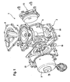
- Fig. 1 shows an inventive motor-pump unit 1 in an exploded view, which comprises a pump 2 with a pump housing 5 and an electric motor 3 driving the pump 2, wherein the motor 3 may be formed, for example, as a DC motor.
- the pump 2 as in particular from the sectional view according to Fig. 2 It can be seen is provided as a double diaphragm pump with two opposite working membranes 4, which is clamped between the pump housing 5 and a working space cover 6 and thereby limits a working space 7.
- the working diaphragm 4 are movable in opposite directions by means of a crank drive 8, which per working diaphragm 4 an eccentric 9 and a connecting rod 10th includes.
- the working space cover 6 has an upper cover 11 and a lower cover 12, which are welded, riveted or screwed together in an air-tight manner.
- the upper cover 11 is provided in plastic and lower cover 12 is formed as a stamped part or sintered part. Also possible is a cost-effective production by means of aluminum die casting.
- inlet and outlet valves are provided in the working space covers 6 inlet and outlet valves, not shown, are provided. From the outlet valve, the ejected air is passed through an outlet channel in the working space cover 6 to an outlet channel in the pump housing 5, which are connected airtight by means of a sealing element.
- the two outlet channels in the pump housing 5 open into an interior 22 of the pump housing 5, the so-called crank chamber, which surrounds the crank drive 8.
- a provided in the pump housing 5 air outlet unit 13 consisting of a filter housing 14, an intermediate bottom 15 and an air outlet cover 16 allows a low-noise blowing out of the air from the interior 22, which thus serves as Schalldämpfungsraum. Furthermore, the air outlet unit 13 comprises a non-illustrated check valve with a one- or multi-part valve body, which prevents a backflow of already expelled air and the penetration of liquid or gaseous substances into the interior 22.
- the airborne sound when the air exits the interior space 22 is reduced by the fact that the air is deflected several times as it flows through the air outlet unit 13 and thereby flows through two filter elements 17, 18 before it exits the air outlet unit 13.
- the pump housing 5 is made of plastic, whereby a cost-effective production is made possible. Like that Fig. 1 and 2 can be removed, between the motor 3 and the pump housing 5, a motor plate 19 is arranged, which is fixed to a motor flange 20 of the pump housing 5 and emits emitted from the motor 3 EMC radiation.
- the pump housing 5 is an in Fig. 1 shown port 23 is evacuated, for example, a connected brake booster.
- a motor shaft 24 simultaneously serves as an eccentric shaft which carries the crank drive 8 with the eccentrics 9 and the connecting rods 10.
- Fig. 3 shows a spatial exploded view of a working diaphragm 4 with a crank drive 8 comprising eccentric 9 and connecting rod 10, wherein the Fig. 4 and 5 enlarged views of the eccentric 9 and the connecting rod 10 can be seen.
- This embodiment of the eccentric 9 requires on the one hand a cost-effective production and a simplified assembly, since the separate mounting of the balance weight 25 on the eccentric 9 by screwing, welding, etc. may be omitted, and on the other hand, a further reduction in component.
- a connecting rod eye 26 of the connecting rod 10 is manufactured as a sintered component and a connecting rod shaft 27 is provided of plastic.
- the attachment of the connecting rod shank 27 to the connecting rod eye 26 is effected by insert molding of an integrally formed on the connecting rod 26 approach 28th
- the working diaphragm 4 can be fastened to the connecting rod shaft 27 in a simple manner by friction welding.
- a ball bearing 29 is pressed into the connecting rod eye 26.
- connection rod 10 is made in one piece as a sintered component.
Landscapes
- Engineering & Computer Science (AREA)
- Mechanical Engineering (AREA)
- General Engineering & Computer Science (AREA)
- Transportation (AREA)
- Reciprocating Pumps (AREA)
- Compressor (AREA)
Description
- Die Erfindung betrifft ein Motor-Pumpenaggregat gemäß dem Oberbegriff des Patentanspruchs 1.
- Zur Bereitstellung von Vakuum für einen pneumatischen Bremskraftverstärker, dessen Innenraum in wenigstens eine Vakuumkammer und eine Arbeitskammer unterteilt ist, werden Vakuumpumpen eingesetzt, die aus der Vakuumkammer Restluft ansaugen und in die Atmosphäre ausstoßen. In der Automobilindustrie werden hierzu in der Regel Flügelzellenpumpen oder Schwenkflügelpumpen eingesetzt. Diese haben prinzipbedingt viel Reibung und müssen geschmiert werden, um eine akzeptable Lebensdauer zu erreichen. Vom Verbrennungsmotor des Kraftfahrzeuges angetriebene Vakuumpumpen mit Flügeln werden daher an den Ölkreislauf des Verbrennungsmotors angeschlossen. Dennoch muss ein nennenswerter Anteil der vom Verbrennungsmotor abgegebenen Leistung zum Antrieb einer solchen Pumpe aufgewendet werden. Und dies auch dann, wenn das Vakuum in der zu evakuierenden Kammer bereits voll ausgebildet ist. Daher ist es sinnvoll, die Vakuumpumpe mit elektrischer Energie zu betreiben und nur dann einzuschalten, wenn der absolute Druck in der Vakuumkammer über einen vorbestimmten Wert steigt.
- Weiterhin kann in Fahrzeugen mit Elektro- bzw. Hybridantrieb die Vakuumpumpe nicht bzw. zeitweise nicht durch den Verbrennungsmotor angetrieben werden. Daher werden in diesen Fahrzeugen elektrisch angetriebene Vakuumpumpen eingesetzt.
- Eine solche elektrisch angetriebene Pumpe mit einem Schmiermittelkreislauf auszustatten oder an einen solchen anzuschließen, würde einen unverhältnismäßig hohen Aufwand bedeuten. Somit kommen für den Einsatz in Kraftfahrzeugen mit Bremsanlagen mit elektrisch angetriebener Vakuumpumpe nur trocken laufende Vakuumpumpen in Frage. In Flügelzellenpumpen wird hierfür das selbstschmierende Material Graphit verwendet, aus dem mit hohem Aufwand die Flügel mit der erforderlichen Präzision hergestellt werden. Daher sind die Bemühungen dahingehend, zur elektrischen Bereitstellung von Bremsvakuum eine Membranpumpe zu verwenden.
- Eine gattungsgemäßes Motor-Pumpenaggregat ist beispielsweise aus der
DE 10 2007 005 223 A1 oder aus derDE 10 2007020538 A1 bekannt. - Es bestehen stets Bestrebungen, die Herstellungskosten sowie den Montageaufwand zu reduzieren. Daher ist es Aufgabe der vorliegenden Erfindung, ein geräuscharmes, kostenreduziertes Motor-Pumpenaggregat bereitzustellen, welches im Vergleich zu dem bekannten, gattungsgemäßen Aggregat einen reduzierten Montageaufwand erfordert. Ferner soll die Bauteilanzahl reduziert werden.
- Die Aufgabe wird erfindungsgemäß dadurch gelöst, dass die Exzenter mit den Wuchtgewichten als Sinterbauteile vorgesehen sind. Hierdurch kann die Montage der Lufteinlasseinheit wesentlich vereinfacht werden und die Bauteilanzahl verringert sich.
- Weitere Merkmale, Vorteile und Anwendungsmöglichkeiten der Erfindung gehen aus der nachfolgenden Beschreibung von einem Ausführungsbeispiel sowie anhand der Zeichnung hervor.
- Es zeigt:
- Figur 1
- ein erfindungsgemäßes Motor-Pumpenaggregat in räumlicher Darstellung;
- Figur 2
- das Motor-Pumpenaggregat gemäß
Fig.1 im Längsschnitt; - Figur 3
- eine Arbeitsmembran des Motor-Pumpenaggregates gemäß
Fig. 1 und2 mit Kurbelantrieb; - Figur 4
- ein Exzenter des Kurbelantriebs gemäß
Fig. 3 mit angeformtem Wuchtgewicht und - Figur 5
- eine Pleuelstange des Kurbelantriebs gemäß
Fig. 3 . -
Fig. 1 zeigt ein erfindungsgemäßes Motor-Pumpenaggregat 1 in einer Explosionsdarstellung, welches eine Pumpe 2 mit einem Pumpengehäuse 5 und einen die Pumpe 2 antreibenden elektrischen Motor 3 umfasst, wobei der Motor 3 beispielsweise als Gleichstrommotor ausgebildet sein kann. - Die Pumpe 2, wie insbesondere aus der Schnittdarstellung gemäß
Fig. 2 ersichtlich ist, ist als Doppelmembranpumpe mit zwei gegenüberliegenden Arbeitsmembranen 4 vorgesehen, welche jeweils zwischen dem Pumpengehäuse 5 und einem Arbeitsraumdeckel 6 eingespannt ist und dadurch einen Arbeitsraum 7 begrenzt. Die Arbeitsmembrane 4 sind mittels eines Kurbelantriebs 8 gegensinnig bewegbar, welcher je Arbeitsmembran 4 einen Exzenter 9 und eine Pleuelstange 10 umfasst. Der Arbeitsraumdeckel 6 weist einen Oberdeckel 11 sowie einen Unterdeckel 12 auf, die luftdicht miteinander verschweißt, vernietet bzw. verschraubt sind. Zur Kostenreduzierung ist der Oberdeckel 11 aus Kunststoff vorgesehen und Unterdeckel 12 ist als Stanzteil oder Sinterteil ausgebildet. Möglich ist auch eine kostengünstige Herstellung mittels Aluminiumdruckguss. - In den Arbeitsraumdeckeln 6 sind nicht gezeigte Einlass- und Auslassventile vorgesehen. Vom dem Auslassventil wird die ausgestoßene Luft über einen Auslasskanal im Arbeitsraumdeckel 6 zu einem Auslasskanal im Pumpengehäuse 5 geleitet, die luftdicht mittels eines Dichtelements verbunden sind. Die beiden Auslasskanäle im Pumpengehäuse 5 münden in einen Innenraum 22 des Pumpengehäuses 5, dem so genannten Kurbelraum, welcher den Kurbelantrieb 8 umgibt.
- Eine in dem Pumpengehäuse 5 vorgesehene Luftauslasseinheit 13 bestehend aus einem Filtergehäuse 14, einem Zwischenboden 15 und einem Luftauslassdeckel 16 ermöglicht ein geräuscharmes Ausblasen der Luft aus dem Innenraum 22, welcher so als Schalldämpfungsraum dient. Weiter umfasst die Luftauslasseinheit 13 ein nicht dargestelltes Rückschlagventil mit einem ein- oder mehrteiligen Ventilkörper, das ein Zurückströmen von bereits ausgestoßener Luft sowie das Eindringen flüssiger oder gasförmiger Substanzen in den Innenraum 22 verhindert.
- Zusätzlich wird der Luftschall beim Austreten der Luft aus dem Innenraum 22 dadurch vermindert, dass die Luft beim Durchströmen der Luftauslasseinheit 13 mehrmals umgelenkt wird und dabei zwei Filterelemente 17,18 durchströmt, bevor sie aus der Luftauslasseinheit 13 austritt.
- Das Pumpengehäuse 5 ist aus Kunststoff vorgesehen, wodurch eine kostengünstige Herstellung ermöglicht wird. Wie den
Fig. 1 und2 entnommen werden kann, ist zwischen dem Motor 3 und dem Pumpengehäuse 5 ein Motorblech 19 angeordnet, welches an einer Motorflanschseite 20 des Pumpengehäuses 5 befestigt ist und vom Motor 3 abgegebene EMV-Strahlen abhält. - Die Befestigung des Motors 3 und des Motorbleches 19 am Pumpengehäuse 5 erfolgt mittels Schraubelementen 21, welche direkt ins Pumpengehäuse 5 eingeschraubt werden.
- Ferner ist am Pumpegehäuse 5 ein in
Fig. 1 gezeigter Anschluss 23 vorgesehen, über beispielsweise ein angeschlossener Bremskraftverstärker evakuiert wird. -
Fig. 2 ist weiter zu entnehmen, dass eine Motorwelle 24 gleichzeitig als Exzenterwelle dient, welche den Kurbelantrieb 8 mit den Exzentern 9 und den Pleuelstangen 10 trägt. - Es ist jedoch auch eine separate Ausführung von Motorwelle und Exzenterwelle möglich.
-
Fig. 3 zeigt in räumlicher Explosions-Darstellung eine Arbeitsmembran 4 mit einem Kurbelantrieb 8 umfassend Exzenter 9 und Pleuelstange 10, wobei denFig. 4 und5 vergrößerte Ansichten des Exzenters 9 und der Pleuelstange 10 zu entnehmen sind. - Wie aus
Fig. 4 deutlich ersichtlich ist, weist der Exzenter 9 zur Schwingungsoptimierung ein einteilig angeformtes Wuchtgewicht 25 auf, wobei der Exzenter 9 und das Wuchtgewicht 25 als Sinterbauteil hergestellt sind. Diese Ausgestaltung des Exzenters 9 bedingt zum einen eine kostengünstige Herstellung und eine vereinfachte Montage, da die separate Montage des Wuchtgewichtes 25 an dem Exzenter 9 durch Verschrauben, Verschweißen etc. entfallen kann, und zum anderen eine weitere Bauteilreduzierung. - Zur weiteren Kostenoptimierung ist ein Pleuelauge 26 der Pleuelstange 10 als Sinterbauteil hergestellt und ein Pleuelschaft 27 ist aus Kunststoff vorgesehen. Die Befestigung des Pleuelschaftes 27 an dem Pleuelauge 26 erfolgt durch Umspritzen eines an dem Pleuelauge 26 angeformten Ansatzes 28.
- Die Arbeitsmembran 4 kann auf dem Pleuelschaft 27 in einfacher Weise durch Reibschweißen befestigt werden. Ein Kugellager 29 wird in das Pleuelauge 26 eingepresst.
- Eine nicht gezeigte Ausführungsform der Erfindung sieht vor, dass die Pleuelstange 10 einteilig als Sinterbauteil hergestellt ist.
-
- 1 Motor-Pumpenaggregat
- 2 Pumpe
- 3 Motor
- 4 Arbeitsmembran
- 5 Pumpengehäuse
- 6 Arbeitsraumdeckel
- 7 Arbeitsraum
- 8 Kurbelantrieb
- 9 Exzenter
- 10 Pleuelstange
- 11 Oberdeckel
- 12 Unterdeckel
- 13 Luftauslasseinheit
- 14 Filtergehäuse
- 15 Zwischenboden
- 16 Luftauslassdeckel
- 17 Filterelement
- 18 Filterelement
- 19 Motorblech
- 20 Motorflanschseite
- 21 Schraubelement
- 22 Innenraum
- 23 Anschluss
- 24 Motorwelle
- 25 Wuchtgewicht
- 26 Pleuelauge
- 27 Pleuelschaft
- 28 Ansatz
- 29 Kugellager
Claims (6)
- Motor-Pumpenaggregat (1), insbesondere zur Bereitstellung von Druck für eine Bremsbetätigungseinrichtung einer Kraftfahrzeugbremsanlage mit einem pneumatischen Bremskraftverstärker, insbesondere einem Vakuumbremskraftverstärker, umfassend eine Pumpe (2) und einen die Pumpe (2) antreibenden elektrischen Motor (3), wobei die Pumpe (2) als Doppelmembranpumpe mit zwei gegenüberliegenden Arbeitsmembranen (4) vorgesehen ist, welche jeweils zwischen einem Pumpengehäuse (5) und einem Arbeitsraumdeckel (6) eingespannt ist und dadurch einen Arbeitsraum (7) begrenzt und welche mittels eines, Exzenter (9) und Pleuelstangen (10) aufweisenden Kurbelantriebs (8) bewegbar sind, wobei dem Arbeitsraum (7) jeweils ein Einlasskanal mit Einlassventil und ein Auslasskanal mit Auslassventil zugeordnet ist, wobei die Auslasskanäle in den Arbeitsraumdeckeln (6) und im Pumpengehäuse (5) derart angeordnet vorgesehen sind, dass aus den Arbeitsräumen (7) verdrängte Luft in einen, den Kurbelantrieb umgebenden Innenraum (22) des Pumpengehäuses (5) geleitet wird, und dass eine Luftauslasseinheit (13) vorgesehen ist, welche ein geräuscharmes Ausblasen der Luft aus dem Innenraum (22) durch Umlenken der Luft ermöglicht, dadurch gekennzeichnet, dass die Exzenter (9) jeweils ein Wuchtgewicht (25) aufweisen, welches einteilig an den Exzenter (9) angeformt vorgesehen ist.
- Motor-Pumpenaggregat nach Anspruch 1, dadurch gekennzeichnet, dass die Exzenter (9) mit den Wuchtgewichten (25) als Sinterbauteile vorgesehen sind.
- Motor-Pumpenaggregat nach Anspruch 1 oder 2, dadurch gekennzeichnet, dass die Pleuelstangen (10) als Sinterbauteile vorgesehen sind.
- Motor-Pumpenaggregat nach Anspruch 1 oder 2, dadurch gekennzeichnet, dass ein Pleuelauge (26) der Pleuelstangen (10) als Sinterbauteil und ein Pleuelschaft (27) aus Kunststoff vorgesehen sind.
- Motor-Pumpenaggregat nach Anspruch 4, dadurch gekennzeichnet, dass die Befestigung des Pleuelschaftes (27) an dem Pleuelauge (26) durch Umspritzen eines Ansatzes (28) des Pleuelauges (26) vorgesehen ist.
- Motor-Pumpenaggregat nach einem der vorangegangenen Ansprüche, dadurch gekennzeichnet, dass die Arbeitsmembrane (4) durch Reibschweißen an den Pleuelstangen (10) befestigt sind.
Applications Claiming Priority (3)
| Application Number | Priority Date | Filing Date | Title |
|---|---|---|---|
| DE102008064151 | 2008-12-19 | ||
| DE102009054502A DE102009054502A1 (de) | 2008-12-19 | 2009-12-10 | Motor-Pumpenaggregat |
| PCT/EP2009/067202 WO2010069963A1 (de) | 2008-12-19 | 2009-12-15 | Motor-pumpenaggregat |
Publications (2)
| Publication Number | Publication Date |
|---|---|
| EP2379887A1 EP2379887A1 (de) | 2011-10-26 |
| EP2379887B1 true EP2379887B1 (de) | 2013-04-10 |
Family
ID=42194333
Family Applications (2)
| Application Number | Title | Priority Date | Filing Date |
|---|---|---|---|
| EP09774679.6A Active EP2379887B1 (de) | 2008-12-19 | 2009-12-15 | Motor-pumpenaggregat |
| EP09774680.4A Active EP2379888B1 (de) | 2008-12-19 | 2009-12-15 | Motor-pumpenaggregat |
Family Applications After (1)
| Application Number | Title | Priority Date | Filing Date |
|---|---|---|---|
| EP09774680.4A Active EP2379888B1 (de) | 2008-12-19 | 2009-12-15 | Motor-pumpenaggregat |
Country Status (7)
| Country | Link |
|---|---|
| US (2) | US8714941B2 (de) |
| EP (2) | EP2379887B1 (de) |
| JP (2) | JP5714504B2 (de) |
| KR (2) | KR101628673B1 (de) |
| CN (2) | CN102257274B (de) |
| DE (2) | DE102009054502A1 (de) |
| WO (2) | WO2010069965A1 (de) |
Families Citing this family (31)
| Publication number | Priority date | Publication date | Assignee | Title |
|---|---|---|---|---|
| DE102009054502A1 (de) * | 2008-12-19 | 2010-06-24 | Continental Teves Ag & Co. Ohg | Motor-Pumpenaggregat |
| DE102009054941A1 (de) | 2009-12-18 | 2011-06-22 | Continental Teves AG & Co. OHG, 60488 | Motor-Pumpenaggregat |
| DE102010042552A1 (de) | 2010-10-18 | 2012-04-19 | Continental Teves Ag & Co. Ohg | Verfahren zur Beschichtung einer Membran einer Membranpumpe für ein Motor-Pumpenaggregat |
| DE102010042553A1 (de) | 2010-10-18 | 2012-04-19 | Continental Teves Ag & Co. Ohg | Pumpenaggregat |
| DE102011006525A1 (de) | 2011-03-31 | 2012-10-04 | Continental Teves Ag & Co. Ohg | Motor-Pumpenaggregat |
| JPWO2013114813A1 (ja) * | 2012-01-31 | 2015-05-11 | アルバック機工株式会社 | ポンプ装置 |
| DE102013201718A1 (de) | 2012-02-01 | 2013-08-01 | Continental Teves Ag & Co. Ohg | Elektromotorisch antreibbares Pumpenaggregat |
| WO2014035382A1 (en) | 2012-08-29 | 2014-03-06 | Otis Elevator Company | Friction brake assembly with an abradable metal foam brake pad |
| DE102013207741A1 (de) * | 2013-04-26 | 2014-10-30 | Continental Teves Ag & Co. Ohg | Pumpenaggregat |
| DE102013220594A1 (de) * | 2013-10-11 | 2015-04-16 | Continental Teves Ag & Co. Ohg | Ausblaseinheit für eine Vakuumpumpe |
| DE102013222119A1 (de) | 2013-10-30 | 2015-04-30 | Continental Teves Ag & Co. Ohg | Vakuumpumpe |
| DE102013222121A1 (de) | 2013-10-30 | 2015-04-30 | Continental Teves Ag & Co. Ohg | Vakuumpumpe |
| DE102013222245A1 (de) | 2013-10-31 | 2015-04-30 | Continental Teves Ag & Co. Ohg | Vakuumpumpe mit einem Deckel |
| DE102014214302A1 (de) | 2014-07-22 | 2016-01-28 | Continental Teves Ag & Co. Ohg | Ausblaseinheit und Pumpenaggregat mit Ausblaseinheit |
| DE102014216721A1 (de) * | 2014-08-22 | 2016-02-25 | Continental Teves Ag & Co. Ohg | Elektromotor-Pumpenaggregat |
| EP3051136B1 (de) * | 2015-01-29 | 2020-04-01 | Pfeiffer Vacuum Gmbh | Vakuumpumpe |
| DE102015205059A1 (de) * | 2015-03-20 | 2016-09-22 | Continental Teves Ag & Co. Ohg | Motorpumpenaggregat mit einer einzelnen elastischen Membran |
| WO2017058309A1 (en) * | 2015-09-30 | 2017-04-06 | Parker-Hannifin Corporation | Integrated valve gasket and enhanced eccentric assembly in a pump or a gas compressor |
| CN107035670A (zh) * | 2017-05-31 | 2017-08-11 | 瑞立集团瑞安汽车零部件有限公司 | 一种车用电动膜片真空泵 |
| DE102017216014A1 (de) * | 2017-09-12 | 2019-03-14 | Robert Bosch Gmbh | Hydraulikaggregat einer Fahrzeugbremsanlage mit einem Exzenterraum |
| CN108757645B (zh) * | 2018-06-19 | 2021-03-12 | 深圳市科斯腾液压设备有限公司 | 一种液压马达及其生产工艺 |
| CN108869240A (zh) * | 2018-07-02 | 2018-11-23 | 上海汽车制动系统有限公司 | 具有滚花芯轴的电动真空泵及其压入方法 |
| CN113944614B (zh) * | 2018-09-30 | 2023-06-20 | 深圳市大疆软件科技有限公司 | 隔膜泵及农业无人机 |
| WO2020115836A1 (ja) * | 2018-12-05 | 2020-06-11 | 東浜工業株式会社 | ブロワー装置 |
| EP3683441B1 (de) * | 2019-01-16 | 2024-08-28 | Groeneveld-BEKA GmbH | Montageeinheit als baugruppe für eine schmierstoffpumpe |
| CN113557359B (zh) | 2019-03-15 | 2023-05-23 | 采埃孚商用车系统欧洲有限公司 | 真空泵以及车辆 |
| CN111306046B (zh) * | 2020-04-07 | 2024-08-13 | 温州瑞立科密汽车电子有限公司 | 一种车用双膜片真空泵 |
| US11549443B2 (en) * | 2020-08-28 | 2023-01-10 | Pratt & Whitney Canada Corp. | Sealing arrangement with vent for an engine component with a service port |
| DE102021207254A1 (de) | 2021-07-08 | 2023-01-12 | Thyssenkrupp Ag | Wellenanordnung, sowie Kompressor |
| CN115076069B (zh) * | 2022-07-01 | 2023-12-01 | 常州市东南电器电机有限公司 | 一种具有防水功能的真空泵 |
| DE102023130757A1 (de) * | 2023-11-07 | 2025-05-08 | Zf Cv Systems Europe Bv | Drucklufterzeugungsvorrichtung und Druckluftversorgungsanlage für ein Fahrzeug, Fahrzeug und Betriebsverfahren zum Betreiben einer Drucklufterzeugungsvorrichtung |
Family Cites Families (20)
| Publication number | Priority date | Publication date | Assignee | Title |
|---|---|---|---|---|
| US2539896A (en) * | 1946-10-28 | 1951-01-30 | American Brake Shoe Co | Air compressor |
| US3877842A (en) * | 1970-01-21 | 1975-04-15 | Itt | Air pumps |
| JPS4719121Y1 (de) * | 1970-10-02 | 1972-06-30 | ||
| KR870002377A (ko) | 1985-08-05 | 1987-03-31 | 미다 가쓰시게 | 자동차용 부압공급장치 |
| JPS62157285A (ja) * | 1985-12-05 | 1987-07-13 | Anretsuto:Kk | ダイヤフラム式ポンプのバランサ−装置 |
| DE3801515A1 (de) * | 1987-01-20 | 1988-07-28 | Thomas Industries Inc | Verdichter fuer fluide, insbesondere membran-luftverdichter |
| JPH0791371A (ja) * | 1993-09-20 | 1995-04-04 | Tokico Ltd | 空気圧縮機用消音器 |
| GB2301151B (en) * | 1995-05-15 | 1999-02-03 | Pirelli Tyres Ltd | Diaphragm pump |
| US5634391A (en) * | 1996-07-09 | 1997-06-03 | Westinghouse Air Brake Co. | Inert plastic coated flexible type diaphragm for application in a sanitary type pump |
| US6382931B1 (en) * | 1998-02-24 | 2002-05-07 | Respironics, Inc. | Compressor muffler |
| JP2000145646A (ja) * | 1998-11-16 | 2000-05-26 | Tanika Denki Hanbai Kk | 膜ポンプ機構とこれを有する酒サーバー |
| DE10114327C2 (de) * | 2001-03-23 | 2003-07-03 | Danfoss Compressors Gmbh | Saugschalldämpfer |
| JP2002371961A (ja) * | 2001-06-18 | 2002-12-26 | Anlet Co Ltd | ブロワ、真空ポンプ等に用いるサイレンサ兼用型処理装置 |
| KR100428551B1 (ko) * | 2001-12-04 | 2004-04-28 | 삼성광주전자 주식회사 | 밀폐형 왕복식 압축기의 크랭크 샤프트 제조방법 |
| JP4694956B2 (ja) * | 2005-12-07 | 2011-06-08 | 日立アプライアンス株式会社 | 密閉形圧縮機 |
| DE102007005223A1 (de) * | 2006-02-10 | 2007-09-13 | Continental Teves Ag & Co. Ohg | Motor-Pumpenaggregat |
| DE102006060645B4 (de) * | 2006-02-10 | 2021-11-04 | Continental Teves Ag & Co. Ohg | Motor-Pumpenaggregat |
| DE102007020538A1 (de) | 2007-01-29 | 2008-10-02 | Continental Teves Ag & Co. Ohg | Motor-Pumpenaggregat |
| DE102008005820A1 (de) | 2007-09-11 | 2009-03-12 | Continental Teves Ag & Co. Ohg | Motor-Pumpenaggregat |
| DE102009054502A1 (de) * | 2008-12-19 | 2010-06-24 | Continental Teves Ag & Co. Ohg | Motor-Pumpenaggregat |
-
2009
- 2009-12-10 DE DE102009054502A patent/DE102009054502A1/de not_active Withdrawn
- 2009-12-10 DE DE102009054499A patent/DE102009054499A1/de not_active Withdrawn
- 2009-12-15 US US13/139,394 patent/US8714941B2/en active Active
- 2009-12-15 CN CN200980150959.0A patent/CN102257274B/zh active Active
- 2009-12-15 WO PCT/EP2009/067204 patent/WO2010069965A1/de not_active Ceased
- 2009-12-15 EP EP09774679.6A patent/EP2379887B1/de active Active
- 2009-12-15 CN CN200980150496.8A patent/CN102257273B/zh active Active
- 2009-12-15 US US13/139,396 patent/US8926293B2/en active Active
- 2009-12-15 EP EP09774680.4A patent/EP2379888B1/de active Active
- 2009-12-15 WO PCT/EP2009/067202 patent/WO2010069963A1/de not_active Ceased
- 2009-12-15 KR KR1020117016789A patent/KR101628673B1/ko not_active Expired - Fee Related
- 2009-12-15 JP JP2011541394A patent/JP5714504B2/ja active Active
- 2009-12-15 JP JP2011541395A patent/JP5726750B2/ja not_active Expired - Fee Related
- 2009-12-15 KR KR1020117016851A patent/KR101628674B1/ko active Active
Also Published As
| Publication number | Publication date |
|---|---|
| KR20110101217A (ko) | 2011-09-15 |
| CN102257274A (zh) | 2011-11-23 |
| EP2379887A1 (de) | 2011-10-26 |
| US20110271670A1 (en) | 2011-11-10 |
| US20110277464A1 (en) | 2011-11-17 |
| DE102009054502A1 (de) | 2010-06-24 |
| CN102257273A (zh) | 2011-11-23 |
| KR20110103430A (ko) | 2011-09-20 |
| US8714941B2 (en) | 2014-05-06 |
| US8926293B2 (en) | 2015-01-06 |
| WO2010069963A1 (de) | 2010-06-24 |
| CN102257273B (zh) | 2014-12-10 |
| KR101628673B1 (ko) | 2016-06-09 |
| CN102257274B (zh) | 2015-05-13 |
| JP2012512986A (ja) | 2012-06-07 |
| DE102009054499A1 (de) | 2010-07-01 |
| EP2379888B1 (de) | 2018-09-12 |
| EP2379888A1 (de) | 2011-10-26 |
| WO2010069965A1 (de) | 2010-06-24 |
| JP5714504B2 (ja) | 2015-05-07 |
| JP5726750B2 (ja) | 2015-06-03 |
| JP2012512985A (ja) | 2012-06-07 |
| KR101628674B1 (ko) | 2016-06-09 |
Similar Documents
| Publication | Publication Date | Title |
|---|---|---|
| EP2379887A1 (de) | Motor-pumpenaggregat | |
| EP2512889B1 (de) | Motor-pumpenaggregat | |
| EP1984221B1 (de) | Motor-pumpenaggregat | |
| EP2193058B1 (de) | Motor-pumpenaggregat | |
| EP2809951B1 (de) | Elektromotorisch antreibbares pumpenaggregat | |
| EP2646302B1 (de) | Motor-pumpenaggregat | |
| EP3183149B1 (de) | Elektromotor-pumpenaggregat | |
| DE4239575C2 (de) | Schalldämpfer für pneumatische Pumpen, insbesondere Flügelzellenpumpen in Kraftfahrzeugen | |
| DE102007020538A1 (de) | Motor-Pumpenaggregat | |
| DE102016203688A1 (de) | Baugruppe für einen Kompressor, insbesondere in einem Automobil | |
| EP3271581B1 (de) | Motorpumpenaggregat mit einer einzelnen elastischen membran | |
| DE102010042553A1 (de) | Pumpenaggregat | |
| EP1588054B1 (de) | Pumpe | |
| WO2007134928A1 (de) | Membranpumpe | |
| DE102006060645B4 (de) | Motor-Pumpenaggregat | |
| DE102011082749A1 (de) | Bremsbetätigungseinheit für eine Kraftfahrzeugbremsanlage und Motor-Pumpenaggregat zur Bereitstellung von Unterdruck für eine Bremsbetätigungseinheit einer Kraftfahrzeugbremsanlage | |
| DE102010042552A1 (de) | Verfahren zur Beschichtung einer Membran einer Membranpumpe für ein Motor-Pumpenaggregat | |
| DE102011006525A1 (de) | Motor-Pumpenaggregat | |
| DE102016112555B4 (de) | Kfz-Hilfsaggregat-Vakuumpumpe | |
| DE102014220619A1 (de) | Motor-Pumpenaggregat |
Legal Events
| Date | Code | Title | Description |
|---|---|---|---|
| PUAI | Public reference made under article 153(3) epc to a published international application that has entered the european phase |
Free format text: ORIGINAL CODE: 0009012 |
|
| 17P | Request for examination filed |
Effective date: 20110719 |
|
| AK | Designated contracting states |
Kind code of ref document: A1 Designated state(s): AT BE BG CH CY CZ DE DK EE ES FI FR GB GR HR HU IE IS IT LI LT LU LV MC MK MT NL NO PL PT RO SE SI SK SM TR |
|
| DAX | Request for extension of the european patent (deleted) | ||
| GRAP | Despatch of communication of intention to grant a patent |
Free format text: ORIGINAL CODE: EPIDOSNIGR1 |
|
| GRAS | Grant fee paid |
Free format text: ORIGINAL CODE: EPIDOSNIGR3 |
|
| GRAA | (expected) grant |
Free format text: ORIGINAL CODE: 0009210 |
|
| AK | Designated contracting states |
Kind code of ref document: B1 Designated state(s): AT BE BG CH CY CZ DE DK EE ES FI FR GB GR HR HU IE IS IT LI LT LU LV MC MK MT NL NO PL PT RO SE SI SK SM TR |
|
| REG | Reference to a national code |
Ref country code: GB Ref legal event code: FG4D Free format text: NOT ENGLISH |
|
| REG | Reference to a national code |
Ref country code: CH Ref legal event code: EP Ref country code: AT Ref legal event code: REF Ref document number: 606162 Country of ref document: AT Kind code of ref document: T Effective date: 20130415 |
|
| REG | Reference to a national code |
Ref country code: IE Ref legal event code: FG4D Free format text: LANGUAGE OF EP DOCUMENT: GERMAN |
|
| REG | Reference to a national code |
Ref country code: DE Ref legal event code: R096 Ref document number: 502009006830 Country of ref document: DE Effective date: 20130606 |
|
| PG25 | Lapsed in a contracting state [announced via postgrant information from national office to epo] |
Ref country code: SI Free format text: LAPSE BECAUSE OF FAILURE TO SUBMIT A TRANSLATION OF THE DESCRIPTION OR TO PAY THE FEE WITHIN THE PRESCRIBED TIME-LIMIT Effective date: 20130410 |
|
| REG | Reference to a national code |
Ref country code: NL Ref legal event code: VDEP Effective date: 20130410 Ref country code: LT Ref legal event code: MG4D |
|
| PG25 | Lapsed in a contracting state [announced via postgrant information from national office to epo] |
Ref country code: GR Free format text: LAPSE BECAUSE OF FAILURE TO SUBMIT A TRANSLATION OF THE DESCRIPTION OR TO PAY THE FEE WITHIN THE PRESCRIBED TIME-LIMIT Effective date: 20130711 Ref country code: IS Free format text: LAPSE BECAUSE OF FAILURE TO SUBMIT A TRANSLATION OF THE DESCRIPTION OR TO PAY THE FEE WITHIN THE PRESCRIBED TIME-LIMIT Effective date: 20130810 Ref country code: ES Free format text: LAPSE BECAUSE OF FAILURE TO SUBMIT A TRANSLATION OF THE DESCRIPTION OR TO PAY THE FEE WITHIN THE PRESCRIBED TIME-LIMIT Effective date: 20130721 Ref country code: LT Free format text: LAPSE BECAUSE OF FAILURE TO SUBMIT A TRANSLATION OF THE DESCRIPTION OR TO PAY THE FEE WITHIN THE PRESCRIBED TIME-LIMIT Effective date: 20130410 Ref country code: SE Free format text: LAPSE BECAUSE OF FAILURE TO SUBMIT A TRANSLATION OF THE DESCRIPTION OR TO PAY THE FEE WITHIN THE PRESCRIBED TIME-LIMIT Effective date: 20130410 Ref country code: PT Free format text: LAPSE BECAUSE OF FAILURE TO SUBMIT A TRANSLATION OF THE DESCRIPTION OR TO PAY THE FEE WITHIN THE PRESCRIBED TIME-LIMIT Effective date: 20130812 Ref country code: FI Free format text: LAPSE BECAUSE OF FAILURE TO SUBMIT A TRANSLATION OF THE DESCRIPTION OR TO PAY THE FEE WITHIN THE PRESCRIBED TIME-LIMIT Effective date: 20130410 Ref country code: NO Free format text: LAPSE BECAUSE OF FAILURE TO SUBMIT A TRANSLATION OF THE DESCRIPTION OR TO PAY THE FEE WITHIN THE PRESCRIBED TIME-LIMIT Effective date: 20130710 Ref country code: NL Free format text: LAPSE BECAUSE OF FAILURE TO SUBMIT A TRANSLATION OF THE DESCRIPTION OR TO PAY THE FEE WITHIN THE PRESCRIBED TIME-LIMIT Effective date: 20130410 |
|
| PG25 | Lapsed in a contracting state [announced via postgrant information from national office to epo] |
Ref country code: PL Free format text: LAPSE BECAUSE OF FAILURE TO SUBMIT A TRANSLATION OF THE DESCRIPTION OR TO PAY THE FEE WITHIN THE PRESCRIBED TIME-LIMIT Effective date: 20130410 Ref country code: HR Free format text: LAPSE BECAUSE OF FAILURE TO SUBMIT A TRANSLATION OF THE DESCRIPTION OR TO PAY THE FEE WITHIN THE PRESCRIBED TIME-LIMIT Effective date: 20130410 Ref country code: BG Free format text: LAPSE BECAUSE OF FAILURE TO SUBMIT A TRANSLATION OF THE DESCRIPTION OR TO PAY THE FEE WITHIN THE PRESCRIBED TIME-LIMIT Effective date: 20130710 Ref country code: CY Free format text: LAPSE BECAUSE OF FAILURE TO SUBMIT A TRANSLATION OF THE DESCRIPTION OR TO PAY THE FEE WITHIN THE PRESCRIBED TIME-LIMIT Effective date: 20130410 Ref country code: LV Free format text: LAPSE BECAUSE OF FAILURE TO SUBMIT A TRANSLATION OF THE DESCRIPTION OR TO PAY THE FEE WITHIN THE PRESCRIBED TIME-LIMIT Effective date: 20130410 |
|
| PG25 | Lapsed in a contracting state [announced via postgrant information from national office to epo] |
Ref country code: SK Free format text: LAPSE BECAUSE OF FAILURE TO SUBMIT A TRANSLATION OF THE DESCRIPTION OR TO PAY THE FEE WITHIN THE PRESCRIBED TIME-LIMIT Effective date: 20130410 Ref country code: EE Free format text: LAPSE BECAUSE OF FAILURE TO SUBMIT A TRANSLATION OF THE DESCRIPTION OR TO PAY THE FEE WITHIN THE PRESCRIBED TIME-LIMIT Effective date: 20130410 Ref country code: DK Free format text: LAPSE BECAUSE OF FAILURE TO SUBMIT A TRANSLATION OF THE DESCRIPTION OR TO PAY THE FEE WITHIN THE PRESCRIBED TIME-LIMIT Effective date: 20130410 |
|
| PLBE | No opposition filed within time limit |
Free format text: ORIGINAL CODE: 0009261 |
|
| STAA | Information on the status of an ep patent application or granted ep patent |
Free format text: STATUS: NO OPPOSITION FILED WITHIN TIME LIMIT |
|
| PG25 | Lapsed in a contracting state [announced via postgrant information from national office to epo] |
Ref country code: RO Free format text: LAPSE BECAUSE OF FAILURE TO SUBMIT A TRANSLATION OF THE DESCRIPTION OR TO PAY THE FEE WITHIN THE PRESCRIBED TIME-LIMIT Effective date: 20130410 Ref country code: IT Free format text: LAPSE BECAUSE OF FAILURE TO SUBMIT A TRANSLATION OF THE DESCRIPTION OR TO PAY THE FEE WITHIN THE PRESCRIBED TIME-LIMIT Effective date: 20130410 |
|
| 26N | No opposition filed |
Effective date: 20140113 |
|
| REG | Reference to a national code |
Ref country code: DE Ref legal event code: R097 Ref document number: 502009006830 Country of ref document: DE Effective date: 20140113 |
|
| BERE | Be: lapsed |
Owner name: CONTINENTAL TEVES A.G. & CO. OHG Effective date: 20131231 |
|
| REG | Reference to a national code |
Ref country code: CH Ref legal event code: PL |
|
| PG25 | Lapsed in a contracting state [announced via postgrant information from national office to epo] |
Ref country code: LU Free format text: LAPSE BECAUSE OF FAILURE TO SUBMIT A TRANSLATION OF THE DESCRIPTION OR TO PAY THE FEE WITHIN THE PRESCRIBED TIME-LIMIT Effective date: 20131215 |
|
| REG | Reference to a national code |
Ref country code: IE Ref legal event code: MM4A |
|
| PG25 | Lapsed in a contracting state [announced via postgrant information from national office to epo] |
Ref country code: BE Free format text: LAPSE BECAUSE OF NON-PAYMENT OF DUE FEES Effective date: 20131231 Ref country code: LI Free format text: LAPSE BECAUSE OF NON-PAYMENT OF DUE FEES Effective date: 20131231 Ref country code: IE Free format text: LAPSE BECAUSE OF NON-PAYMENT OF DUE FEES Effective date: 20131215 Ref country code: CH Free format text: LAPSE BECAUSE OF NON-PAYMENT OF DUE FEES Effective date: 20131231 |
|
| PG25 | Lapsed in a contracting state [announced via postgrant information from national office to epo] |
Ref country code: MC Free format text: LAPSE BECAUSE OF FAILURE TO SUBMIT A TRANSLATION OF THE DESCRIPTION OR TO PAY THE FEE WITHIN THE PRESCRIBED TIME-LIMIT Effective date: 20130410 |
|
| PG25 | Lapsed in a contracting state [announced via postgrant information from national office to epo] |
Ref country code: SM Free format text: LAPSE BECAUSE OF FAILURE TO SUBMIT A TRANSLATION OF THE DESCRIPTION OR TO PAY THE FEE WITHIN THE PRESCRIBED TIME-LIMIT Effective date: 20130410 |
|
| REG | Reference to a national code |
Ref country code: DE Ref legal event code: R084 Ref document number: 502009006830 Country of ref document: DE |
|
| PG25 | Lapsed in a contracting state [announced via postgrant information from national office to epo] |
Ref country code: TR Free format text: LAPSE BECAUSE OF FAILURE TO SUBMIT A TRANSLATION OF THE DESCRIPTION OR TO PAY THE FEE WITHIN THE PRESCRIBED TIME-LIMIT Effective date: 20130410 |
|
| PG25 | Lapsed in a contracting state [announced via postgrant information from national office to epo] |
Ref country code: HU Free format text: LAPSE BECAUSE OF FAILURE TO SUBMIT A TRANSLATION OF THE DESCRIPTION OR TO PAY THE FEE WITHIN THE PRESCRIBED TIME-LIMIT; INVALID AB INITIO Effective date: 20091215 Ref country code: MK Free format text: LAPSE BECAUSE OF FAILURE TO SUBMIT A TRANSLATION OF THE DESCRIPTION OR TO PAY THE FEE WITHIN THE PRESCRIBED TIME-LIMIT Effective date: 20130410 |
|
| PG25 | Lapsed in a contracting state [announced via postgrant information from national office to epo] |
Ref country code: MT Free format text: LAPSE BECAUSE OF FAILURE TO SUBMIT A TRANSLATION OF THE DESCRIPTION OR TO PAY THE FEE WITHIN THE PRESCRIBED TIME-LIMIT Effective date: 20130410 |
|
| REG | Reference to a national code |
Ref country code: FR Ref legal event code: PLFP Year of fee payment: 7 |
|
| REG | Reference to a national code |
Ref country code: AT Ref legal event code: MM01 Ref document number: 606162 Country of ref document: AT Kind code of ref document: T Effective date: 20141215 |
|
| PG25 | Lapsed in a contracting state [announced via postgrant information from national office to epo] |
Ref country code: AT Free format text: LAPSE BECAUSE OF NON-PAYMENT OF DUE FEES Effective date: 20141215 |
|
| REG | Reference to a national code |
Ref country code: FR Ref legal event code: PLFP Year of fee payment: 8 |
|
| REG | Reference to a national code |
Ref country code: FR Ref legal event code: PLFP Year of fee payment: 9 |
|
| REG | Reference to a national code |
Ref country code: DE Ref legal event code: R081 Ref document number: 502009006830 Country of ref document: DE Owner name: CONTINENTAL AUTOMOTIVE TECHNOLOGIES GMBH, DE Free format text: FORMER OWNER: CONTINENTAL TEVES AG & CO. OHG, 60488 FRANKFURT, DE Ref country code: DE Ref legal event code: R081 Ref document number: 502009006830 Country of ref document: DE Owner name: AUMOVIO GERMANY GMBH, DE Free format text: FORMER OWNER: CONTINENTAL TEVES AG & CO. OHG, 60488 FRANKFURT, DE |
|
| REG | Reference to a national code |
Ref country code: GB Ref legal event code: 732E Free format text: REGISTERED BETWEEN 20230216 AND 20230222 |
|
| REG | Reference to a national code |
Ref country code: DE Ref legal event code: R081 Ref document number: 502009006830 Country of ref document: DE Owner name: CONTINENTAL AUTOMOTIVE TECHNOLOGIES GMBH, DE Free format text: FORMER OWNER: CONTINENTAL AUTOMOTIVE TECHNOLOGIES GMBH, 30165 HANNOVER, DE Ref country code: DE Ref legal event code: R081 Ref document number: 502009006830 Country of ref document: DE Owner name: AUMOVIO GERMANY GMBH, DE Free format text: FORMER OWNER: CONTINENTAL AUTOMOTIVE TECHNOLOGIES GMBH, 30165 HANNOVER, DE |
|
| PGFP | Annual fee paid to national office [announced via postgrant information from national office to epo] |
Ref country code: GB Payment date: 20251223 Year of fee payment: 17 |
|
| PGFP | Annual fee paid to national office [announced via postgrant information from national office to epo] |
Ref country code: FR Payment date: 20251223 Year of fee payment: 17 |
|
| PGFP | Annual fee paid to national office [announced via postgrant information from national office to epo] |
Ref country code: CZ Payment date: 20251128 Year of fee payment: 17 |
|
| REG | Reference to a national code |
Ref country code: DE Ref legal event code: R081 Ref document number: 502009006830 Country of ref document: DE Owner name: AUMOVIO GERMANY GMBH, DE Free format text: FORMER OWNER: CONTINENTAL AUTOMOTIVE TECHNOLOGIES GMBH, 30175 HANNOVER, DE |
|
| PGFP | Annual fee paid to national office [announced via postgrant information from national office to epo] |
Ref country code: DE Payment date: 20251231 Year of fee payment: 17 |