EP2378029B1 - Konsoltrageinrichtung zum Anschluss an ein Gerüst - Google Patents
Konsoltrageinrichtung zum Anschluss an ein Gerüst Download PDFInfo
- Publication number
- EP2378029B1 EP2378029B1 EP11002826.3A EP11002826A EP2378029B1 EP 2378029 B1 EP2378029 B1 EP 2378029B1 EP 11002826 A EP11002826 A EP 11002826A EP 2378029 B1 EP2378029 B1 EP 2378029B1
- Authority
- EP
- European Patent Office
- Prior art keywords
- console
- profile
- holder device
- scaffolding
- holder
- Prior art date
- Legal status (The legal status is an assumption and is not a legal conclusion. Google has not performed a legal analysis and makes no representation as to the accuracy of the status listed.)
- Active
Links
Images


Classifications
-
- E—FIXED CONSTRUCTIONS
- E04—BUILDING
- E04G—SCAFFOLDING; FORMS; SHUTTERING; BUILDING IMPLEMENTS OR AIDS, OR THEIR USE; HANDLING BUILDING MATERIALS ON THE SITE; REPAIRING, BREAKING-UP OR OTHER WORK ON EXISTING BUILDINGS
- E04G5/00—Component parts or accessories for scaffolds
- E04G5/06—Consoles; Brackets
-
- E—FIXED CONSTRUCTIONS
- E04—BUILDING
- E04G—SCAFFOLDING; FORMS; SHUTTERING; BUILDING IMPLEMENTS OR AIDS, OR THEIR USE; HANDLING BUILDING MATERIALS ON THE SITE; REPAIRING, BREAKING-UP OR OTHER WORK ON EXISTING BUILDINGS
- E04G5/00—Component parts or accessories for scaffolds
- E04G5/06—Consoles; Brackets
- E04G5/061—Consoles; Brackets specially adapted for attachment to scaffolds
-
- E—FIXED CONSTRUCTIONS
- E04—BUILDING
- E04G—SCAFFOLDING; FORMS; SHUTTERING; BUILDING IMPLEMENTS OR AIDS, OR THEIR USE; HANDLING BUILDING MATERIALS ON THE SITE; REPAIRING, BREAKING-UP OR OTHER WORK ON EXISTING BUILDINGS
- E04G5/00—Component parts or accessories for scaffolds
- E04G5/08—Scaffold boards or planks
Definitions
- the present invention relates to a console support device for connection to a stand with a stand tube having a longitudinal axis with a support profile with a longitudinal direction at / in which at least one console cover can be connected or attached transversely to the longitudinal direction, and a to the scaffold side of the frame arranged adjacent construction for releasable connection the console support means to the upright tube of the framework, wherein the connecting structure on the scaffold side has a substantially perpendicular to the longitudinal direction of the support profile extending axis of rotation, which forms a detachable and rotatable connection to the stator tube of the framework, and below the axis of rotation in the frame-side front end of the support section Endanschlagisme is present which is at least partially brought into contact with the outer contour of the stator tube in the stator tube connected to the frame axis of rotation in contact, such that the console support means in the Stander tube releasably connected state under the action of gravity in a substantially perpendicular to the longitudinal axis of the stator tube
- thermal insulation In old buildings, it is often the case that the thermal insulation is insufficient due to the existing construction. Therefore, in order to reduce heating costs, old buildings are subsequently coated with a heat insulation system on the outside. As part of the thermal insulation renovation approximately 20 to 25 cm thick thermal insulation panels (thermal insulation systems such as ETICS) are attached to the outside of the masonry. For this, the old building must be scaffolded with a scaffolding system. A problem with the installation of such old buildings is the existing due to the strong thermal insulation increased wall distance of the scaffold to be equipped wall. Normally, the distance from the lining edge of the scaffolding to the facade should not exceed 30 cm. This workroom is usually claimed by the plasterer and painter.
- the frameworks for WDSV measures are placed at a distance of about 50 to 60 cm in front of the facade.
- the known consoles are successively dismantled, usually in layers.
- the known console devices have welded half-couplings and are screwed to the uprights of the setting frame.
- the known consoles next to the actual support profile for the coverings have a diagonal brace, which is arranged below the support profile and is supported on the stator tube of the scaffold system.
- the coupling for the support profile for Connection to the framework is usually connected in a recess of a Stellrahmeneckblechs a setting frame. The assembly and disassembly of such consoles is very time consuming.
- a console support device with the features of the preamble of claim 1 is disclosed.
- This has a Auflagerstrebe for supporting pads, which is supported on the underside of a diagonal strut. Both struts are connected to a holding strut, which has a relatively long upward-facing supernatant.
- the retaining strut In the upper end region, the retaining strut has two parallel spaced projecting retaining tabs each with a recess. When mounting the device, the retaining tabs are to be positioned on both sides of a vertical stem, such that existing on the vertical stem recesses are aligned with the recesses of the retaining tabs.
- a locking pin is inserted through the recesses, so that the device is connected to the vertical stem.
- a sliding shoe which in the assembled state rests on the outside of the vertical shaft as a result of the effect of the weight of the device.
- the JP S49 117637 U discloses a Konsoltrag adopted with a vertical support member and a rotatably connected to the vertical support member connected cantilever horizontal support member on which the pads can be arranged.
- the horizontal support member can be pivoted upward if necessary.
- the vertical element is connected in its upper edge region via a pipe coupling to the vertical stem and the lower end portion of the vertical support member is supported on the outside of the vertical stem.
- the CH 506 685 A shows a triangular console, each having an open U-profile element in its upper and lower, the vertical stem end region facing, wherein the upper U-profile element has recesses, which in the assembly with recesses of the Vertical stem must be made to coincide and then a socket pin is inserted through the recesses.
- the lower U-profile is in the mounted state on the outer wall of the vertical stem.
- the US 5,388,663 A. discloses a triangular bracket support device, in which the upper end face region of the support device is hooked via a hook element to a hung on the vertical stem in a groove ring element in the assembled state.
- the free end region of the diagonal brace of the triangular console support device is supported in the mounted state on the outside of the vertical tube.
- the JP 2002 038711 A discloses a triangular Konsoltragelement in which the support profile for connection of the pads in its front end region has a connected wedge-shaped element which is inserted during assembly in a present on the vertical stem pocket.
- the free end region of the diagonal bar of the triangular console support device is supported in the mounted state on the outside of the vertical stem.
- the present invention has the object or the technical problem of ensuring a quick assembly or disassembly of a console device, in particular without the use of additional screws, which ensures a permanently reliable function, the occupancy of the gusset plate a setting frame existing recesses does not require and
- further connection possibilities of a scaffold anchor to a scaffold made possible by the connection according to the invention, such that an additional connection of a scaffold anchor in the region of the gusset plate a frame of a scaffold is still possible without any problems.
- the Konsoltrageinrichtrung invention should also be made compact, economically producible and ensure easy and easy handling during assembly or disassembly.
- bracket support device according to the invention of the type mentioned is given by the features of independent claim 1.
- the console support device is thus characterized in that the support profile is connected to the frame side projecting, in particular inclined upwardly extending, projection unit is connected in the free end region with the projection unit welded transversely to the longitudinal axis of the pivot pin is formed, which forms the axis of rotation and which is designed to be insertable into a hole recess passing through the stator tube from one side, wherein the bracket support device is designed such that it can be led upwards with its free end to the upright tube and the bolt can be inserted from the side into the continuous recess of the Stander tube is pushed and then the console support device is folded down until the Endantschtechnik comes with the outer contour of the stator tube to the stop.
- the connection of the console support means to the stator tube designed particularly simple.
- the console support means must be attached only obliquely inclined upward, wherein the pivot pin is inserted laterally into the through recess of the stator tube. After release of this position, the console support automatically moves to a position which is perpendicular to the longitudinal axis of the stator tube, so that further additional installation measures are not required.
- a simple disassembly of the bracket support device according to the invention is possible by this is folded after removal of the scaffold plating in a simple manner up and the pivot pin is brought by appropriate displacement with the recess of the stator tube out of engagement.
- a particularly advantageous embodiment of the console support device according to the invention is characterized in that the form-locking unit each has a right or left, parallel spaced, projecting to the frame side side flap, the clear inner spacing is substantially slightly larger than the outer diameter of the stator tube.
- the form-fitting unit of the support console device according to the invention is characterized in that the form-fitting unit has a partial circle cross-section which essentially corresponds in curvature to the circular cross-section of the stator tube.
- the console support device is characterized in that a fast, screwless installation is possible. It is designed basically hinged, for mounting or dismounting the console device is inclined to the stand can be arranged, and can be easily inserted into a continuous recess of the stator tube in this state. As a result of their own weight then takes place a rotation or folding around this axis of rotation down until the Stops stop unit on the outer circumference of the stator tube.
- the two-sided tabs that laterally pivot the stand tube laterally secure the console additionally against a shift in the transverse direction.
- the console support device solves the problem that the console usually required for the Sanierablauf is mounted in the recess in the gusset plate, which is not the case with the bracket support device according to the invention, since it is anchored above the gusset plate in a continuous recess on the stator tube.
- the recess on the gusset plate is free to connect a coupling for a scaffold anchor, which is mandatory for securing the scaffold to the wall of the building.
- the scaffold anchor must be mounted deeper, which limits the passage height within the framework, which problem is not given in the console support device according to the invention.
- a collision with the scaffold anchor, whose scaffold coupling is mounted in the gusset plate of the adjusting frame, is not given, since the console support means can be connected above the gusset plate to the stator tube of the scaffold in a simple manner.
- a particularly advantageous embodiment of the bracket support device according to the invention is characterized in that the support section on the side facing the frame side end facing the free end overlapping unit which has the edge region an insertable Konsolbelags at least partially overlaps the upper side.
- the support profile of the bracket support device according to the invention is designed as an upwardly open U-profile, in which at least one console cover can be suspended by means of suspension units.
- an advantageous embodiment is characterized in that the support profile has a front end plate arranged transversely to the longitudinal direction in its end region facing a wall side.
- a structurally particularly simple embodiment which guarantees a high load-bearing capacity of the bracket support according to the invention, is characterized in that a first L-shaped angle profile is arranged in the end region of the support profile facing the frame side, the first upper leg of which is arranged parallel to the longitudinal direction and forms the overlapping unit and its second lower leg is frontally connected to the support profile.
- Another structurally particularly simple embodiment which ensures a particularly economical production, is characterized in that in the frame side facing end portion of the support section, a second L-shaped angle section is arranged, the first, parallel to the longitudinal direction leg forms the right side tab and whose longitudinal axis is substantially perpendicular to the second leg forms the Endanschlagisme.
- the length of the support profile can preferably be designed so that it corresponds substantially to the width of one or more connectable console coverings.
- the bracket support device is preferably made of steel or aluminum.
- An advantageous embodiment is characterized in that the underside of the Stirnendplatte spaced from the bottom of the support profile is present, so that a drainage possibility for any accumulating rainwater is given.
- An economical production which ensures a permanently reliable function with high load-bearing capacity, is characterized by the fact that all connections of the components of the console support device are welded.
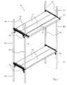
- a section of a scaffold 50 is shown schematically, wherein the frame has 50 stacked adjusting frames 58, and each setting frame has a left and right stand tube 30 which are connected on the upper side with a cross bar 62, wherein in each case in the corner region between cross bar 62 and stator tube 30th a gusset plate 60 is welded.
- the cross bar 62 two scaffold pads 52 are suspended from above, which are mounted on the corresponding opposite crossbar of the adjacent adjusting frame 58.
- a support bracket 10 is connected to the stator tube 30 on the side facing the viewer, wherein a console pad 54 is connected to both console support means 10.
- FIG. 1 An embodiment of a console support device 10 will be described below with reference to FIG Fig. 2 to 5 described.
- the bracket support device 10 has a support profile 12, which is formed as an upwardly open U-profile and in the longitudinal direction L has a length substantially equal to the width of a Konsolbelages 54 or a multiple of this width.
- a Konsolbelag 54 are suspended from above to the support section 12, including the Konsolbelag 54 in its front end corresponding suspension units 56 (see Fig. 7 ) or Ein rehabilitationkrallen has.
- a front end plate 14 In its wall-side free end portion of a front end plate 14 is welded to the support section 12, the lower edge spaced from the bottom of the support section 12 is present.
- the console support device 10 has a connection construction for connection to a stator tube 30.
- a projection tab 36 is formed and further obliquely upward to the frame side G towards extending projection unit 22 is formed.
- a bolt unit 24 which forms an axis of rotation D, is welded transversely to the longitudinal direction L. This bolt unit 24 is adapted to be inserted into a through-hole recess of a stator tube 30, so that in the inserted state, the console device 10 is rotatable about this axis of rotation D on the stator tube 30.
- a standing first L-shaped angle section 32 is present, whose width substantially corresponds to the clear inner spacing of the webs of the U-shaped support profile 12.
- the first angle section 32 has an upwardly projecting over the support section 12, facing the wall W side facing first leg; which is designed as overlapping unit 20, that is, a suspended in the support section 12 Konsolbelag 54 (see Fig. 7 ) is overlapped by this overlapping unit 20 in its end edge region facing the frame of the overlapping unit 20 and thus the console pad 54 is secured against tilting.
- the downwardly facing second leg 26 is welded to the inner wall of the webs of the support section 12.
- a second lying L-shaped angle section 34 is connected, the first leg is arranged parallel to the longitudinal direction L and projecting towards the frame side G and thus forms a second lateral tab 18.2, which is spaced parallel to the first lateral tab 18.1 runs.
- the transverse to the longitudinal direction L arranged second leg 18.3 of the angle section 34 is partially offset below the first angle profile 32 is present and welded thereto.
- the frame facing the side of the second leg 18.3 forms a Endanschlaghow 16 abuts when connected to the stator tube 30 bolt unit 24 under the action of the dead weight of the bracket support 10 on the outside of the stator tube 30.
- the clear inner spacing of the first and second lateral tabs 18.1, 18.2 is only slightly larger than the outer diameter D1 of the stator tube 30.
- a fixation of Console support device 10 achieved on the stator tube 30.
- the distance between the axis of rotation D and the plane of the end stop unit 16 seen in a plan view substantially corresponds to the outer radius D2 of the stator tube 30, which means that the console support device 10 is always at right angles to the state connected to the stator tube 30 under the effect of its own weight with respect to the longitudinal direction L to the stator tube 30 is present.
- FIG. 6 and 7 the assembly process of the console support device 10 is shown schematically.
- the console support device is guided with its free end upwards inclined to the stator tube 30 and the bolt 24 inserted from the side into the through recess of the stator tube 30.
- the console support device 10 is folded down (see Arrow K in Fig. 6 ) until the Endanschlagtechnik 16 with the outer contour of the stator tube 30 comes to a stop (see Fig. 7 ).
- the left and right lugs 18.1, 18.2 each laterally comprise the outer wall of the stator tube 30, so that a secure fixed position of the bracket support means 10 is given to the stator tube 30.
- the console pad 54 is suspended laterally retracting by means of its suspension units 56 in the U-shaped support section 12, wherein in this state, the overlay unit 20, the frame-side suspension unit 56 of the console covering 54 overlaps the upper side in some areas. During dismantling, the procedure must be reversed accordingly.
Landscapes
- Engineering & Computer Science (AREA)
- Architecture (AREA)
- Mechanical Engineering (AREA)
- Civil Engineering (AREA)
- Structural Engineering (AREA)
- Mutual Connection Of Rods And Tubes (AREA)
- Supports For Pipes And Cables (AREA)
Priority Applications (1)
| Application Number | Priority Date | Filing Date | Title |
|---|---|---|---|
| PL11002826T PL2378029T3 (pl) | 2010-04-14 | 2011-04-05 | Urządzenie nośne konsoli do połączenia z rusztowaniem |
Applications Claiming Priority (1)
| Application Number | Priority Date | Filing Date | Title |
|---|---|---|---|
| DE202010005021U DE202010005021U1 (de) | 2010-04-14 | 2010-04-14 | Konsoltrageinrichtung zum Anschluss an ein Gerüst |
Publications (3)
| Publication Number | Publication Date |
|---|---|
| EP2378029A2 EP2378029A2 (de) | 2011-10-19 |
| EP2378029A3 EP2378029A3 (de) | 2013-12-18 |
| EP2378029B1 true EP2378029B1 (de) | 2015-12-16 |
Family
ID=42372131
Family Applications (1)
| Application Number | Title | Priority Date | Filing Date |
|---|---|---|---|
| EP11002826.3A Active EP2378029B1 (de) | 2010-04-14 | 2011-04-05 | Konsoltrageinrichtung zum Anschluss an ein Gerüst |
Country Status (3)
| Country | Link |
|---|---|
| EP (1) | EP2378029B1 (pl) |
| DE (1) | DE202010005021U1 (pl) |
| PL (1) | PL2378029T3 (pl) |
Cited By (1)
| Publication number | Priority date | Publication date | Assignee | Title |
|---|---|---|---|---|
| DE202021105059U1 (de) | 2021-09-20 | 2021-10-12 | Rux Gmbh | Aufsteckkonsole zur Befestigung an einem Gerüst |
Families Citing this family (7)
| Publication number | Priority date | Publication date | Assignee | Title |
|---|---|---|---|---|
| DE102011008315B4 (de) * | 2011-01-11 | 2014-07-10 | Rux Gmbh | Konsole für Baugerüste |
| EP2497875A1 (en) * | 2011-03-07 | 2012-09-12 | Graziano Rustico | Supporting structure |
| ES2530315B1 (es) * | 2013-08-27 | 2016-01-13 | Inveral, S.A. | Travesaño de soporte de una plataforma de trabajo. |
| EP2949834A1 (de) * | 2014-05-30 | 2015-12-02 | Tobler AG | Befestigungskonsole für Gerüstbretter, Gerüstbrett und Gerüst |
| US20160032600A1 (en) * | 2014-08-01 | 2016-02-04 | Wls Intellectual Property Limited | Guard for scaffolding |
| DE202015101813U1 (de) | 2015-04-14 | 2016-07-15 | C. O. Weise Gmbh & Co. Kg | Gerüstbelag |
| DE102019201649A1 (de) * | 2019-02-08 | 2020-08-13 | Peri Gmbh | Konsole in Form eines Horizontalriegels zur werkzeugfreien Befestigung an einem Gerüst |
Family Cites Families (6)
| Publication number | Priority date | Publication date | Assignee | Title |
|---|---|---|---|---|
| CH506685A (de) * | 1970-04-29 | 1971-04-30 | Baechli Jules | Gerüstträger |
| JPS523308Y2 (pl) * | 1973-01-27 | 1977-01-24 | ||
| DE3522307A1 (de) * | 1985-06-21 | 1987-01-02 | Wolfgang Baumann | Zusatzvorrichtung fuer einen von bauhandwerkern verwendbaren stuetzbock |
| US5388663A (en) * | 1993-12-08 | 1995-02-14 | Phillippe; Michel | Portable walkway systems |
| JP2002038711A (ja) * | 2000-07-21 | 2002-02-06 | Haruyuki Nishida | 仮設足場における踏板支持構造及び仮設足場 |
| DE20103596U1 (de) * | 2001-03-01 | 2001-05-10 | Günter Rux GmbH, 58135 Hagen | Konsole für Baugerüste |
-
2010
- 2010-04-14 DE DE202010005021U patent/DE202010005021U1/de not_active Expired - Lifetime
-
2011
- 2011-04-05 PL PL11002826T patent/PL2378029T3/pl unknown
- 2011-04-05 EP EP11002826.3A patent/EP2378029B1/de active Active
Cited By (1)
| Publication number | Priority date | Publication date | Assignee | Title |
|---|---|---|---|---|
| DE202021105059U1 (de) | 2021-09-20 | 2021-10-12 | Rux Gmbh | Aufsteckkonsole zur Befestigung an einem Gerüst |
Also Published As
| Publication number | Publication date |
|---|---|
| EP2378029A2 (de) | 2011-10-19 |
| PL2378029T3 (pl) | 2016-06-30 |
| DE202010005021U1 (de) | 2010-07-29 |
| EP2378029A3 (de) | 2013-12-18 |
Similar Documents
| Publication | Publication Date | Title |
|---|---|---|
| EP2378029B1 (de) | Konsoltrageinrichtung zum Anschluss an ein Gerüst | |
| DE19655284B4 (de) | Zerlegbares Fassadengerüst | |
| EP1395723A2 (de) | Zerlegbares gerüst | |
| EP1005598A1 (de) | Fachwerk-modulgerüstsystem | |
| EP2499311B1 (de) | Seitenschutzgitter und seitenschutzsystem | |
| EP4114777B1 (de) | Schutzvorrichtung bei montagearbeiten an einer fahrtreppe oder einem fahrsteig | |
| WO2018126328A1 (de) | Pfosten für eine pfosten-riegel-konstruktion | |
| EP3574164B1 (de) | Konsole zur befestigung von fassadenelementen | |
| DE29912557U1 (de) | Konsoleinrichtung für Gerüste | |
| DE102010006560A1 (de) | Tragvorrichtung und Schalungssystem | |
| EP2884035B1 (de) | Lösbare halterung für eine brandschutzscheibe | |
| DE102010004807A1 (de) | Abhubsicherung für Gerüste | |
| EP4079991B1 (de) | Geländerholm, gerüst, verfahren zum errichten eines gerüsts sowie verwendung eines geländerholms in einem gerüst | |
| DE102011008315A1 (de) | Konsole für Baugerüste | |
| EP0736648B1 (de) | Gerüst | |
| DE10112372A1 (de) | Verbindungskonstruktion für Bauteile eines Systemgerüsts, Kupplungseinheit und Gerüstrahmen hierfür | |
| EP2275625B1 (de) | Gerüstkonstruktion für ein Hauptgerüst und zweites Gerüst, insbesondere Podestgerüsttreppe | |
| EP2949834A1 (de) | Befestigungskonsole für Gerüstbretter, Gerüstbrett und Gerüst | |
| WO2002066767A1 (de) | Verbindungskonstruktion für bauteile eines systemgerüsts, kupplungseinheit und gerüstrahmen hierfür | |
| DE102023113911B3 (de) | Erweiterungskonsole für den Gerüstbau | |
| DE102010052873B4 (de) | Unterdecke für Brandschutzzwecke | |
| EP3354818A1 (de) | Längenausgleichsanordnung für baugerüste | |
| DE102012218672A1 (de) | Konsole für ein Fassadengerüst mit einer verschiebbar gelagerten Teilkonsole | |
| DE202021105059U1 (de) | Aufsteckkonsole zur Befestigung an einem Gerüst | |
| DE102024106388A1 (de) | Eckkonsole |
Legal Events
| Date | Code | Title | Description |
|---|---|---|---|
| AK | Designated contracting states |
Kind code of ref document: A2 Designated state(s): AL AT BE BG CH CY CZ DE DK EE ES FI FR GB GR HR HU IE IS IT LI LT LU LV MC MK MT NL NO PL PT RO RS SE SI SK SM TR |
|
| AX | Request for extension of the european patent |
Extension state: BA ME |
|
| PUAI | Public reference made under article 153(3) epc to a published international application that has entered the european phase |
Free format text: ORIGINAL CODE: 0009012 |
|
| PUAL | Search report despatched |
Free format text: ORIGINAL CODE: 0009013 |
|
| AK | Designated contracting states |
Kind code of ref document: A3 Designated state(s): AL AT BE BG CH CY CZ DE DK EE ES FI FR GB GR HR HU IE IS IT LI LT LU LV MC MK MT NL NO PL PT RO RS SE SI SK SM TR |
|
| AX | Request for extension of the european patent |
Extension state: BA ME |
|
| RIC1 | Information provided on ipc code assigned before grant |
Ipc: E04G 5/06 20060101AFI20131112BHEP |
|
| 17P | Request for examination filed |
Effective date: 20140618 |
|
| RBV | Designated contracting states (corrected) |
Designated state(s): AL AT BE BG CH CY CZ DE DK EE ES FI FR GB GR HR HU IE IS IT LI LT LU LV MC MK MT NL NO PL PT RO RS SE SI SK SM TR |
|
| 17Q | First examination report despatched |
Effective date: 20141001 |
|
| GRAP | Despatch of communication of intention to grant a patent |
Free format text: ORIGINAL CODE: EPIDOSNIGR1 |
|
| RIC1 | Information provided on ipc code assigned before grant |
Ipc: E04G 5/08 20060101AFI20150520BHEP Ipc: E04G 5/06 20060101ALI20150520BHEP |
|
| INTG | Intention to grant announced |
Effective date: 20150609 |
|
| GRAS | Grant fee paid |
Free format text: ORIGINAL CODE: EPIDOSNIGR3 |
|
| GRAL | Information related to payment of fee for publishing/printing deleted |
Free format text: ORIGINAL CODE: EPIDOSDIGR3 |
|
| GRAR | Information related to intention to grant a patent recorded |
Free format text: ORIGINAL CODE: EPIDOSNIGR71 |
|
| GRAS | Grant fee paid |
Free format text: ORIGINAL CODE: EPIDOSNIGR3 |
|
| GRAA | (expected) grant |
Free format text: ORIGINAL CODE: 0009210 |
|
| INTG | Intention to grant announced |
Effective date: 20151028 |
|
| AK | Designated contracting states |
Kind code of ref document: B1 Designated state(s): AL AT BE BG CH CY CZ DE DK EE ES FI FR GB GR HR HU IE IS IT LI LT LU LV MC MK MT NL NO PL PT RO RS SE SI SK SM TR |
|
| REG | Reference to a national code |
Ref country code: GB Ref legal event code: FG4D Free format text: NOT ENGLISH |
|
| REG | Reference to a national code |
Ref country code: CH Ref legal event code: EP |
|
| REG | Reference to a national code |
Ref country code: IE Ref legal event code: FG4D Free format text: LANGUAGE OF EP DOCUMENT: GERMAN |
|
| REG | Reference to a national code |
Ref country code: AT Ref legal event code: REF Ref document number: 765639 Country of ref document: AT Kind code of ref document: T Effective date: 20160115 |
|
| REG | Reference to a national code |
Ref country code: DE Ref legal event code: R096 Ref document number: 502011008492 Country of ref document: DE |
|
| REG | Reference to a national code |
Ref country code: CH Ref legal event code: NV Representative=s name: ISLER AND PEDRAZZINI AG, CH |
|
| REG | Reference to a national code |
Ref country code: SE Ref legal event code: TRGR |
|
| REG | Reference to a national code |
Ref country code: NL Ref legal event code: FP |
|
| REG | Reference to a national code |
Ref country code: LT Ref legal event code: MG4D |
|
| PG25 | Lapsed in a contracting state [announced via postgrant information from national office to epo] |
Ref country code: LT Free format text: LAPSE BECAUSE OF FAILURE TO SUBMIT A TRANSLATION OF THE DESCRIPTION OR TO PAY THE FEE WITHIN THE PRESCRIBED TIME-LIMIT Effective date: 20151216 Ref country code: HR Free format text: LAPSE BECAUSE OF FAILURE TO SUBMIT A TRANSLATION OF THE DESCRIPTION OR TO PAY THE FEE WITHIN THE PRESCRIBED TIME-LIMIT Effective date: 20151216 Ref country code: NO Free format text: LAPSE BECAUSE OF FAILURE TO SUBMIT A TRANSLATION OF THE DESCRIPTION OR TO PAY THE FEE WITHIN THE PRESCRIBED TIME-LIMIT Effective date: 20160316 |
|
| PG25 | Lapsed in a contracting state [announced via postgrant information from national office to epo] |
Ref country code: FI Free format text: LAPSE BECAUSE OF FAILURE TO SUBMIT A TRANSLATION OF THE DESCRIPTION OR TO PAY THE FEE WITHIN THE PRESCRIBED TIME-LIMIT Effective date: 20151216 Ref country code: RS Free format text: LAPSE BECAUSE OF FAILURE TO SUBMIT A TRANSLATION OF THE DESCRIPTION OR TO PAY THE FEE WITHIN THE PRESCRIBED TIME-LIMIT Effective date: 20151216 Ref country code: LV Free format text: LAPSE BECAUSE OF FAILURE TO SUBMIT A TRANSLATION OF THE DESCRIPTION OR TO PAY THE FEE WITHIN THE PRESCRIBED TIME-LIMIT Effective date: 20151216 |
|
| REG | Reference to a national code |
Ref country code: FR Ref legal event code: PLFP Year of fee payment: 6 |
|
| PG25 | Lapsed in a contracting state [announced via postgrant information from national office to epo] |
Ref country code: CZ Free format text: LAPSE BECAUSE OF FAILURE TO SUBMIT A TRANSLATION OF THE DESCRIPTION OR TO PAY THE FEE WITHIN THE PRESCRIBED TIME-LIMIT Effective date: 20151216 Ref country code: ES Free format text: LAPSE BECAUSE OF FAILURE TO SUBMIT A TRANSLATION OF THE DESCRIPTION OR TO PAY THE FEE WITHIN THE PRESCRIBED TIME-LIMIT Effective date: 20151216 Ref country code: IT Free format text: LAPSE BECAUSE OF FAILURE TO SUBMIT A TRANSLATION OF THE DESCRIPTION OR TO PAY THE FEE WITHIN THE PRESCRIBED TIME-LIMIT Effective date: 20151216 |
|
| PG25 | Lapsed in a contracting state [announced via postgrant information from national office to epo] |
Ref country code: BE Free format text: LAPSE BECAUSE OF NON-PAYMENT OF DUE FEES Effective date: 20160430 Ref country code: PT Free format text: LAPSE BECAUSE OF FAILURE TO SUBMIT A TRANSLATION OF THE DESCRIPTION OR TO PAY THE FEE WITHIN THE PRESCRIBED TIME-LIMIT Effective date: 20160418 Ref country code: IS Free format text: LAPSE BECAUSE OF FAILURE TO SUBMIT A TRANSLATION OF THE DESCRIPTION OR TO PAY THE FEE WITHIN THE PRESCRIBED TIME-LIMIT Effective date: 20160416 Ref country code: EE Free format text: LAPSE BECAUSE OF FAILURE TO SUBMIT A TRANSLATION OF THE DESCRIPTION OR TO PAY THE FEE WITHIN THE PRESCRIBED TIME-LIMIT Effective date: 20151216 Ref country code: SM Free format text: LAPSE BECAUSE OF FAILURE TO SUBMIT A TRANSLATION OF THE DESCRIPTION OR TO PAY THE FEE WITHIN THE PRESCRIBED TIME-LIMIT Effective date: 20151216 Ref country code: SK Free format text: LAPSE BECAUSE OF FAILURE TO SUBMIT A TRANSLATION OF THE DESCRIPTION OR TO PAY THE FEE WITHIN THE PRESCRIBED TIME-LIMIT Effective date: 20151216 Ref country code: RO Free format text: LAPSE BECAUSE OF FAILURE TO SUBMIT A TRANSLATION OF THE DESCRIPTION OR TO PAY THE FEE WITHIN THE PRESCRIBED TIME-LIMIT Effective date: 20151216 |
|
| REG | Reference to a national code |
Ref country code: DE Ref legal event code: R097 Ref document number: 502011008492 Country of ref document: DE |
|
| PLBE | No opposition filed within time limit |
Free format text: ORIGINAL CODE: 0009261 |
|
| STAA | Information on the status of an ep patent application or granted ep patent |
Free format text: STATUS: NO OPPOSITION FILED WITHIN TIME LIMIT |
|
| PG25 | Lapsed in a contracting state [announced via postgrant information from national office to epo] |
Ref country code: DK Free format text: LAPSE BECAUSE OF FAILURE TO SUBMIT A TRANSLATION OF THE DESCRIPTION OR TO PAY THE FEE WITHIN THE PRESCRIBED TIME-LIMIT Effective date: 20151216 |
|
| 26N | No opposition filed |
Effective date: 20160919 |
|
| GBPC | Gb: european patent ceased through non-payment of renewal fee |
Effective date: 20160405 |
|
| PG25 | Lapsed in a contracting state [announced via postgrant information from national office to epo] |
Ref country code: LU Free format text: LAPSE BECAUSE OF FAILURE TO SUBMIT A TRANSLATION OF THE DESCRIPTION OR TO PAY THE FEE WITHIN THE PRESCRIBED TIME-LIMIT Effective date: 20160405 |
|
| REG | Reference to a national code |
Ref country code: IE Ref legal event code: MM4A |
|
| PG25 | Lapsed in a contracting state [announced via postgrant information from national office to epo] |
Ref country code: GB Free format text: LAPSE BECAUSE OF NON-PAYMENT OF DUE FEES Effective date: 20160405 |
|
| PG25 | Lapsed in a contracting state [announced via postgrant information from national office to epo] |
Ref country code: SI Free format text: LAPSE BECAUSE OF FAILURE TO SUBMIT A TRANSLATION OF THE DESCRIPTION OR TO PAY THE FEE WITHIN THE PRESCRIBED TIME-LIMIT Effective date: 20151216 |
|
| REG | Reference to a national code |
Ref country code: FR Ref legal event code: PLFP Year of fee payment: 7 |
|
| PG25 | Lapsed in a contracting state [announced via postgrant information from national office to epo] |
Ref country code: IE Free format text: LAPSE BECAUSE OF NON-PAYMENT OF DUE FEES Effective date: 20160405 |
|
| REG | Reference to a national code |
Ref country code: FR Ref legal event code: PLFP Year of fee payment: 8 |
|
| PG25 | Lapsed in a contracting state [announced via postgrant information from national office to epo] |
Ref country code: HU Free format text: LAPSE BECAUSE OF FAILURE TO SUBMIT A TRANSLATION OF THE DESCRIPTION OR TO PAY THE FEE WITHIN THE PRESCRIBED TIME-LIMIT; INVALID AB INITIO Effective date: 20110405 Ref country code: CY Free format text: LAPSE BECAUSE OF FAILURE TO SUBMIT A TRANSLATION OF THE DESCRIPTION OR TO PAY THE FEE WITHIN THE PRESCRIBED TIME-LIMIT Effective date: 20151216 |
|
| PG25 | Lapsed in a contracting state [announced via postgrant information from national office to epo] |
Ref country code: MK Free format text: LAPSE BECAUSE OF FAILURE TO SUBMIT A TRANSLATION OF THE DESCRIPTION OR TO PAY THE FEE WITHIN THE PRESCRIBED TIME-LIMIT Effective date: 20151216 Ref country code: MC Free format text: LAPSE BECAUSE OF FAILURE TO SUBMIT A TRANSLATION OF THE DESCRIPTION OR TO PAY THE FEE WITHIN THE PRESCRIBED TIME-LIMIT Effective date: 20151216 Ref country code: MT Free format text: LAPSE BECAUSE OF FAILURE TO SUBMIT A TRANSLATION OF THE DESCRIPTION OR TO PAY THE FEE WITHIN THE PRESCRIBED TIME-LIMIT Effective date: 20151216 Ref country code: GR Free format text: LAPSE BECAUSE OF FAILURE TO SUBMIT A TRANSLATION OF THE DESCRIPTION OR TO PAY THE FEE WITHIN THE PRESCRIBED TIME-LIMIT Effective date: 20151216 |
|
| PG25 | Lapsed in a contracting state [announced via postgrant information from national office to epo] |
Ref country code: BG Free format text: LAPSE BECAUSE OF FAILURE TO SUBMIT A TRANSLATION OF THE DESCRIPTION OR TO PAY THE FEE WITHIN THE PRESCRIBED TIME-LIMIT Effective date: 20151216 |
|
| PG25 | Lapsed in a contracting state [announced via postgrant information from national office to epo] |
Ref country code: AL Free format text: LAPSE BECAUSE OF FAILURE TO SUBMIT A TRANSLATION OF THE DESCRIPTION OR TO PAY THE FEE WITHIN THE PRESCRIBED TIME-LIMIT Effective date: 20151216 |
|
| P01 | Opt-out of the competence of the unified patent court (upc) registered |
Effective date: 20230516 |
|
| REG | Reference to a national code |
Ref country code: DE Ref legal event code: R082 Ref document number: 502011008492 Country of ref document: DE Representative=s name: GLEIM PETRI PATENT- UND RECHTSANWALTSPARTNERSC, DE |
|
| PGFP | Annual fee paid to national office [announced via postgrant information from national office to epo] |
Ref country code: TR Payment date: 20250326 Year of fee payment: 15 |
|
| PGFP | Annual fee paid to national office [announced via postgrant information from national office to epo] |
Ref country code: NL Payment date: 20250422 Year of fee payment: 15 |
|
| PGFP | Annual fee paid to national office [announced via postgrant information from national office to epo] |
Ref country code: DE Payment date: 20250428 Year of fee payment: 15 |
|
| PGFP | Annual fee paid to national office [announced via postgrant information from national office to epo] |
Ref country code: FR Payment date: 20250422 Year of fee payment: 15 |
|
| PGFP | Annual fee paid to national office [announced via postgrant information from national office to epo] |
Ref country code: CH Payment date: 20250501 Year of fee payment: 15 |
|
| PGFP | Annual fee paid to national office [announced via postgrant information from national office to epo] |
Ref country code: AT Payment date: 20250416 Year of fee payment: 15 |
|
| PGFP | Annual fee paid to national office [announced via postgrant information from national office to epo] |
Ref country code: SE Payment date: 20250423 Year of fee payment: 15 |
|
| PGFP | Annual fee paid to national office [announced via postgrant information from national office to epo] |
Ref country code: PL Payment date: 20260324 Year of fee payment: 16 |