EP2377652B1 - Lagersystem zum Halten von provisorischen Formaten von Brettern - Google Patents
Lagersystem zum Halten von provisorischen Formaten von Brettern Download PDFInfo
- Publication number
- EP2377652B1 EP2377652B1 EP11174222.7A EP11174222A EP2377652B1 EP 2377652 B1 EP2377652 B1 EP 2377652B1 EP 11174222 A EP11174222 A EP 11174222A EP 2377652 B1 EP2377652 B1 EP 2377652B1
- Authority
- EP
- European Patent Office
- Prior art keywords
- rips
- cutting
- storage
- boards
- cut
- Prior art date
- Legal status (The legal status is an assumption and is not a legal conclusion. Google has not performed a legal analysis and makes no representation as to the accuracy of the status listed.)
- Revoked
Links
Images


Classifications
-
- B—PERFORMING OPERATIONS; TRANSPORTING
- B23—MACHINE TOOLS; METAL-WORKING NOT OTHERWISE PROVIDED FOR
- B23D—PLANING; SLOTTING; SHEARING; BROACHING; SAWING; FILING; SCRAPING; LIKE OPERATIONS FOR WORKING METAL BY REMOVING MATERIAL, NOT OTHERWISE PROVIDED FOR
- B23D47/00—Sawing machines or sawing devices working with circular saw blades, characterised only by constructional features of particular parts
- B23D47/04—Sawing machines or sawing devices working with circular saw blades, characterised only by constructional features of particular parts of devices for feeding, positioning, clamping, or rotating work
-
- B—PERFORMING OPERATIONS; TRANSPORTING
- B23—MACHINE TOOLS; METAL-WORKING NOT OTHERWISE PROVIDED FOR
- B23Q—DETAILS, COMPONENTS, OR ACCESSORIES FOR MACHINE TOOLS, e.g. ARRANGEMENTS FOR COPYING OR CONTROLLING; MACHINE TOOLS IN GENERAL CHARACTERISED BY THE CONSTRUCTION OF PARTICULAR DETAILS OR COMPONENTS; COMBINATIONS OR ASSOCIATIONS OF METAL-WORKING MACHINES, NOT DIRECTED TO A PARTICULAR RESULT
- B23Q15/00—Automatic control or regulation of feed movement, cutting velocity or position of tool or work
-
- B—PERFORMING OPERATIONS; TRANSPORTING
- B23—MACHINE TOOLS; METAL-WORKING NOT OTHERWISE PROVIDED FOR
- B23D—PLANING; SLOTTING; SHEARING; BROACHING; SAWING; FILING; SCRAPING; LIKE OPERATIONS FOR WORKING METAL BY REMOVING MATERIAL, NOT OTHERWISE PROVIDED FOR
- B23D59/00—Accessories specially designed for sawing machines or sawing devices
- B23D59/008—Accessories specially designed for sawing machines or sawing devices comprising computers
-
- B—PERFORMING OPERATIONS; TRANSPORTING
- B23—MACHINE TOOLS; METAL-WORKING NOT OTHERWISE PROVIDED FOR
- B23Q—DETAILS, COMPONENTS, OR ACCESSORIES FOR MACHINE TOOLS, e.g. ARRANGEMENTS FOR COPYING OR CONTROLLING; MACHINE TOOLS IN GENERAL CHARACTERISED BY THE CONSTRUCTION OF PARTICULAR DETAILS OR COMPONENTS; COMBINATIONS OR ASSOCIATIONS OF METAL-WORKING MACHINES, NOT DIRECTED TO A PARTICULAR RESULT
- B23Q3/00—Devices holding, supporting, or positioning work or tools, of a kind normally removable from the machine
- B23Q3/02—Devices holding, supporting, or positioning work or tools, of a kind normally removable from the machine for mounting on a work-table, tool-slide, or analogous part
- B23Q3/10—Auxiliary devices, e.g. bolsters, extension members
- B23Q3/105—Auxiliary supporting devices independent of the machine tool
-
- B—PERFORMING OPERATIONS; TRANSPORTING
- B27—WORKING OR PRESERVING WOOD OR SIMILAR MATERIAL; NAILING OR STAPLING MACHINES IN GENERAL
- B27B—SAWS FOR WOOD OR SIMILAR MATERIAL; COMPONENTS OR ACCESSORIES THEREFOR
- B27B5/00—Sawing machines working with circular or cylindrical saw blades; Components or equipment therefor
- B27B5/02—Sawing machines working with circular or cylindrical saw blades; Components or equipment therefor characterised by a special purpose only
- B27B5/06—Sawing machines working with circular or cylindrical saw blades; Components or equipment therefor characterised by a special purpose only for dividing plates in parts of determined size, e.g. panels
- B27B5/065—Sawing machines working with circular or cylindrical saw blades; Components or equipment therefor characterised by a special purpose only for dividing plates in parts of determined size, e.g. panels with feedable saw blades, e.g. arranged on a carriage
-
- Y—GENERAL TAGGING OF NEW TECHNOLOGICAL DEVELOPMENTS; GENERAL TAGGING OF CROSS-SECTIONAL TECHNOLOGIES SPANNING OVER SEVERAL SECTIONS OF THE IPC; TECHNICAL SUBJECTS COVERED BY FORMER USPC CROSS-REFERENCE ART COLLECTIONS [XRACs] AND DIGESTS
- Y10—TECHNICAL SUBJECTS COVERED BY FORMER USPC
- Y10T—TECHNICAL SUBJECTS COVERED BY FORMER US CLASSIFICATION
- Y10T83/00—Cutting
- Y10T83/647—With means to convey work relative to tool station
- Y10T83/6571—With means to store work articles
Definitions
- the present invention generally relates to a storage system comprising:
- Such a storage system is known from JORG TIEDEMANN: "Intelligente Transport- und Handlingssysteme im Plattenzuexcellent",HOB, vol. 2005, no. 09, 1 September 2005 (2005-09-01), pages 47-52 , which discloses the preamble of claim 1. Additionally, the present invention relates to the use of such storage system in a system for controlling cutting of materials.
- glass can be cut into pieces which can serve as a window in a cupboard, mirror, a door.
- various elements making up an object can be obtained from a cutting process or a process involving cutting and further processing using tools such as drills, milling machines, CNC machines, knifes, guillotine shears etc.
- a first step towards reducing the amount of time is to have machines which are able to perform certain functions automatically. For instance, instead of having an operator enter each cut manually at the time of performing the cut, the cutting machine may be able to process a complete cutting plan which details all the parts that have to be cut from the board.
- a wooden board which has dimensions of 3000mm x 4500mm and which is illustrated by Fig. 1 .
- the board has to be cut into three equal parts of 1000mm x 1500mm, two equal parts of 1000mm x 2250mm and five equal parts of 1000mm x 900mm wide.
- an efficient way would be to cut the board into three rips of 1000mm x 4500mm and then divide each of the rips in the three, two or five equal parts respectively.
- an operator would have to specify each cut when feeding a board or rip to the machine.
- the operator would place the board of 3000mm x 4500mm on the machine and use the control panel of the machine to enter the dimensions where each cut has to be made. Then the operator would feed the first rip and enter the dimensions for each part of that rip, etc.
- a complete layout of the board and the pieces that have to be cut from the board can be entered into the machine, for instance by an operator prior to starting the cutting process or automatically when the cutting machine supports computer aided manufacturing or is equipped with a processor to handle such layouts. In such case, an operator's interaction may be limited to feed boards and rips and retrieving rips and pieces from the machine.
- the automated cutting machines are designed to take a cutting layout and process the layout hierarchically on a level-by-level basis. This means that the existing cutting machines can take a board which is cut into rips which form the first level and each rip is further processed into smaller parts which forms a second level and these smaller parts can be processed even further in a third and subsequent levels.
- a board enters the cutting device and rips are obtained from the cutting device, then each rip is in turn cut into smaller parts which in turn can also be further processed.
- angular beam saws which are saws with two cutting axis positioned under an angle from each other, it is possible to invert a layout in order to combine the last rip from the first stack with the first rip from the second stack. However, this is only done for identical rips and a need for an identical further processing of such rips.
- an angular beam saw is a more complex cutting device which can cut a rip via the first saw on the first axis and then process a rip immediately thereafter using the second saw on the second axis.
- each cut requires a certain time to complete as the board or rip has to be fed into the cutting machine, the cuts have to be made and the result has to be removed from the machine. In addition, any waste or unused material has to be recovered and be disposed of or stored. For this example it is assumed that each cut takes 15 seconds and that adding a board or rip to the machine and removing the parts takes 30 seconds for each board or rip. In the above example that results 135 seconds of cutting time for nine cuts, 30 seconds to feed the board and retrieve the rips, 30 seconds to feed the first rip and retrieve the three equal parts, 30 seconds to feed the second rip and retrieve the two equal parts and 30 seconds to feed the third rip and recover the five equal parts which in total is 255 seconds for processing the board into the required pieces. If a second board has to be turned into exactly the same parts as in the above example, it could take up to twice as long when each of the boards is cut individually.
- European Patent Application EP 0 891 847 entitled “A System for Defining and Making Wooden Furniture Panels” describes a system for sawing panels with in between storage (storage station 10) for further processing.
- the in between stacking of strips with equal width in EP 0 891 847 serves for gluing together such strip elements of equal width (6a, 6b) in order to form a continuous strip, that is then cut crossways into strips of predefined lengths. In other words, there is no in between stacking in order to optimize the further processing of strips to reduce cutting cycles.
- a saw is a way of physically dividing a piece of material in two pieces by brute force. Saws spinning at high speed rip through the material and remove a bit of material between the two pieces. Although a saw is much stronger than the material itself, there is always some wear on the saw blade. This is especially the case when cutting hard materials such as stones or metal plates or sheets. Other cutting techniques such as a laser are less prone to the effects of wear because there is no physical contact between the material that is cut and the cutting device or there is no tearing apart of the material. However materials such as lasers, water-jet based systems, etc. require a significant amount of power in order to operate. Consequentially, reducing the number of cuts while cutting a material in pieces does not only reduce the time requirement in order to obtain the required pieces, it can also reduce the costs for repairing or replacing worn down equipment and the power consumption.
- Another element in the production process of pieces via cutting processes is waste management.
- the above given example was based on a board which has a dimension that perfectly fits the needs of the finished pieces.
- additional cuts would be necessary to reduce the board to 3000mm x 4500mm.
- These additional cuts may result in a piece of 1000mm x 6000mm and a piece of 3000mm x 1500mm or a piece of 1000mm x 4500mm and a piece of 4000mm x 1500mm. Either way, these two pieces would not be used in this example and are therefore considered as excess.
- the excess material can be used for future layouts which are made out of the same material and require rips and pieces which can be obtained from the excess material.
- excess material is any material that is left over from cutting a board, rip or part which can be used at a later point in time and waste or waste material is material which is left over from cutting a board, rip or part which cannot or will not be used at a later point in time and which is discarded.
- the machines which are used for processing the materials themselves may be subject to problems as well.
- the above described factors and problems are present regardless of the machines that are used for the cutting and processing of the materials.
- Manually entering dimensions or automatically configuring a machine with a layout does not reduce the time it takes to feed the machine or the time it takes for all the cuts to complete nor does it change wear or power consumption or the waste management.
- older machines such as those which have a control panel which is based on switches, levers and buttons and is not computerized may not be able to provide the same functions to an operator as a computerized machine.
- cutting using layouts requires certain processing capacities on the cutting machine which are typically not present in a non-computerized machine which has a start/stop button, buttons to enter dimensions and a few status lights and other control buttons. It would therefore be advantageous to be able to upgrade existing machines to support new control devices without significant investments in new machines or changes to the control systems of the existing machines.
- New control devices could either replace existing control panels for the machines or may interact with the machines in combination with or in addition to the existing control devices. This shows that various problems exist with today's machines for cutting materials and devices for controlling such machines.
- An objective of the present invention is to provide a control system for cutting materials which is able to reduce the time wherein all cuts are made. Another objective of the present invention is to reduce the amount of waste resulting from the cutting of materials and to facilitate the re-use of excess material. Another objective of the present invention is to enable existing devices to support the control system of the present invention and to enable existing devices to support other additional control functionality. Another objective of the invention is to cut the boards, rips and/or parts in such a way that further operations on the boards, rip and/or parts are possible and more accurate and that also assembling is taken into account.
- a control module for controlling the cutting of a first rip out of a first board and a second rip out of the first board or out of a second board, the system comprising a control module, the control module comprising:
- the instructions can be given to an operator via a display screen or audible system, which means that devices used for cutting and processing do not need to contain the control module itself. Instead, it may be a separate computer or embedded device with a display or audio interface which instructs an operator on the various steps to execute.
- the instructions to the operator can take the form of graphical representations of the steps to take, a drawing of a cutting plan to be executed which may be a detailed plan or plan of the level currently being processed, via a video or multimedia animation, via a textual description of the actions, etc.
- the machine comprises the control module or is able to execute the control module as software instructions
- the machine may be able to automatically stack and/or align and process the rips and boards.
- the instructions are for instance electrical signals sent from the control module to the machine executing the cutting, stacking or further processing.
- Stacking the boards or rips means that a number of rips or boards are placed on top of each other.
- cutting devices have certain constraints on the volume of material that can be placed in the machine for cutting. This means that a stack can only have a certain height.
- the example given here is based on two identical layouts to be obtained from two boards illustrates how beneficial stacking boards can be.
- the present invention is however especially designed to process layouts wherein it is not mandatory that stacked rips or boards are completely identical in their further processing of the subsequent levels.
- the current level that is being cut such as the first level which are the first rips obtained from a boards, is identical except where the non-identical section is waste.
- the second level may be different for each element obtained in the cutting of the first level.
- the current level does not even have to be identical, for instance waste may be present in one or more rips of the current level which are not present in all the rips of the current level.
- the rips can be obtained from the same, first board or from different boards such as a first board and a second board.
- Different boards can be of the same material or may even be from a different type of material.
- the boards will be of the same material such as all wood or all metal but the characteristics of boards may vary such as thickness, kind of material, colour, etc.
- the present invention is independent from the type of material and the number of rips or boards that are stacked. However, by taking into account the dimensions of the machines used in cutting and processing boards and rips, it is possible to avoid stacks which are too high. This may however be resolved by both stacking and aligning stacks or boards or rips next to each other.
- the simultaneous processing can be cutting, such as dividing rips into smaller pieces but may also include other processing such as drilling, milling, painting, grinding, adding masking tape to cover cut-off sides, etc.
- Simultaneous processing may also be an intermediate step in between two cuts. For instance, rips can be stacked, then adjusted in size using a milling machine and then be separated again because the next set of cuts for those two rips does not overlap.
- An alternative intermediate step could be the application of masking tape or edge banding on the sides before further cuts. The latter may for instance be advantageous in a scenario where the edges that have to be finished by edge banding are too narrow for the edge banding process.
- a part of a rip or an entire rip may undergo the edge banding processing before the parts are cut out of the rip.
- the stacking or simultaneous processing of boards or rips is postponed until another operation has been completed.
- the other operation may be performed on a stack of boards or rips or may be performed on each rip or board independently. For instance, it is possible that two rips are cut into the same pieces but that one rip needs holes in certain pieces whereas the other rip does not require any drilling. In such case, it is possible to postpone the stacking and simultaneous cutting into parts until after the drilling of the holes in one of the rips.
- the control module of the present invention provides instructions in order to improve the cutting sequence of rips and boards, reduce waste material.
- the present invention achieves this result by using a cutting device not in its automatic mode to cut complete boards according to the hierarchical level-by-level sequence.
- the present invention uses the cutting device in its manual modus but in an automated fashion (programming cut by cut). Having the ability of controlling the machine as if it was a manual machine provides the ability to cut anything in any desired sequence and by doing this in an automated fashion, the chances for errors are reduced significantly.
- the present invention may stack and/or align boards or rips if further processing at lower levels is not identical for all the boards or rips in the stack. If the current cutting level of stacking is also not identical, the non-identical part has to be waste or can be used to create later useable or frequently used components in order to enable stacking.
- a certain board may need to be cut in a series of rips forming the first level. Each rip of the first level is cut into parts forming a second level and the second level parts may be different and even requiring additional further cutting into subsequent levels. If only the first levels are identical, they can be cut together even if the subsequent levels are completely different. In other words, various boards can be cut into rips simultaneously whereas the parts of each of those rips may be different. If certain lower levels are identical, they can be stacked again for further processing.
- the first level is considered as the current cutting level and any subsequent levels are created from the result of the first level or the current level.
- the present invention is able to process stacks of identical first levels regardless of how subsequent levels should be processed or even non-identical first levels if the non-identical parts are waste or can be used at a later time.
- system for controlling the cutting according to the present invention further comprises storage means for holding temporary formats.
- the storage means of the system for controlling the cutting according to the present invention comprise:
- Rips and boards can be stacked for further processing.
- the storage may be an automated storage system which is able to move the rip to an appropriate storage place.
- the storage can be an additional device which uses transport rolls or bands to move rips and boards to a storage location or a hedgehog storage which rotates into the correct storage spot for a particular piece.
- the storage system may also be based on a number of storage places wherein a person manually places the rips.
- the complexity of the storage may depend on the goal of the storage and the need for any tracking of materials in the storage may also depend on the purpose of the stored material.
- a simple storage location may be sufficient such as a rack which can hold a number of rips or parts.
- An operator or an automated storage machine may be able to place rips or parts in the storage location until these rips or parts are needed for further processing without any need for complex tracking or authorization systems.
- the storage system can be based upon an authorization and tracking system.
- the tracking system keeps track of which board, rip and part is stored at what location in the storage. This can be achieved by registering the board, rip or part and the location in storage where it is located or removed from. This way, there is a complete overview of which boards, rips and parts are where in the storage.
- the storage system can further contain an authorization system which is able to indicate whether a certain board, rip or part may be added to or removed from the storage via a visual, textual and/or audible signal. Especially when coupled to a system which plans the layouts and the use of excess in the execution of the layouts, this can lead to an increase in the use of excess material and thus in the reduction of the total amount of waste material that has to be disposed.
- the identifying of the boards, rips and parts and the locations within the storage can be done using tags such as RFID tags, NFC tags, barcodes, alphanumeric identifiers, symbols, colours, etc. It is however advantageous to use identifiers which can be recognized using a scanner such as an RFID tag or a barcode. This way, an operator can scan the tag of a board, rip or part and the location and the tracking system is able to link that information together to know what is stored where. Similarly, such tags make it easy to determine whether a certain board, rip or part is reserved for cutting or processing or whether a certain board, rip or part is in fact excess and free for use.
- An advantage of the authorization is that operators are able to find physically earlier excess material for new processing, for instance to replace a damaged rip or part.
- Another advantage is that by being able to track what is stored where and by having an authorization system, it is possible to have an exact overview of what is in storage. This way it is possible to instruct a user where a rip can be found which is to be stacked with one or more other rips. These instructions can also be sent to an automated storage system in order to store and retrieve boards, rips or parts. Due to the tracking and authorizing of additions and removals from the storage, it is possible to monitor the actions of a machine or operator. As a result, it is possible to reduce the amount of errors because a cutting device may be aware that a wrong board or rip is placed on the cutting machine and thus an error message can be given on a display or via an audible signal.
- the storage means can also be used independently from the simultaneous processing of boards and rips. For instance in a wood processing facility where processing is done manually, it can be used by the employees to keep track of their parts and enable a higher use of excess material in order to reduce the waste.
- system for controlling the cutting according to the present invention further comprises a cutting device for cutting said first rip out of said first board and for cutting said second rip out of said second board, the cutting device having a control interface.
- system for controlling the cutting according to the present invention further comprises a conversion device, the conversion device comprising:
- the conversion device in the system for controlling the cutting according to the present invention further comprises means for converting the one or more instructions into one or more converted instructions, the one or more converted instructions being in a format interpretable by the cutting device and said means for providing the one or more instructions are adapted to provide the one or more converted instructions to the control interface of the cutting device.
- a first way of enabling the present invention to operate with older and existing machines is by integrating the control module into an independent device which instructs an operator.
- a second way is by using a conversion device which translates instructions from the control module into converted instructions which can be executed by a cutting device.
- Each cutting device has a specific format or syntax which defines how information is entered and how the machine is controlled.
- Some cutting machines have an advanced computerized input device which can process the layouts for boards and which can retrieve such layouts via a computer network or from a storage medium such as a floppy disc, optical storage device, Universal Serial Bus memory device, flash memory device, etc.
- Other cutting machines have a control panel with buttons that can be used to configure the machine or instruct the machine on which cuts are to be made.
- the conversion device of the present invention can be used to add functionality to the existing cutting devices.
- the conversion device can be connected between the control interface of the cutting device and the control panel which initially was connected via that control interface to the cutting device such as the computer or PLC.
- the conversion device further also contains a connection for an additional controller such as the control module of the present invention or a computer or embedded device executing software which operates as the control module according to the present invention.
- the conversion device may act as a simple T-junction in the connection between the control panel and the control interface of a cutting device which enables the connection of another device to the control interface.
- the control module is able to send instructions to the conversion device, which in turn can convert the instructions from the control module into the protocol of the cutting device.
- this can result in a conversion into a file with instructions which is parsed by the cutting device or it's control system.
- it can result in a set of keyboard strokes or other key activations which are known to the cutting device or control panel and which result in the execution of the instructions.
- the conversion can be into the same type of signals as those generated by the control device which is normally used to control the cutting device.
- the output from the conversion device is a number of signals which are the same as signals sent by the control panel of the cutting device normally manually entered by the operator.
- the advantage of such a conversion module is that existing cutting machines are able to benefit from the benefits of stacking and simultaneously processing rips and boards.
- the existing machines do not need to be altered in a significant way because the conversion device may be used as an intermediate connector between the control interface of the cutting device and the controller of the cutting device.
- the conversion occurs in the conversion device.
- a part or all of the conversion may also be done by the control module of the present invention.
- the control module may be aware of various cutting devices and the protocol thereof.
- the control module may have an output which is already according to that protocol and thus processable by the cutting device.
- the conversion device is only a physical connection between the various devices.
- the conversion device may also be used independently from a system which is aware of stacking and simultaneous processing of rips and boards. This way, existing cutting devices which are purely based on manual control by an operator via a control panel can be adapted to process complete layouts. The layouts are processed by an external device such as a computer which in turn provides instructions to the cutting device via the conversion device and to the operator via a display or audio system. Similarly, the conversion device can also be used to introduce a storage system in environments where boards, rips, parts or excess material are not tracked or not controlled by an authorization system in order to reduce the amount of waste. The conversion device may further also be used to extend the abilities of processing devices for other materials than wood. For instance, CNC machines, metal processing machines, drills, mills, etc.
- system for controlling the cutting according to the present invention further comprises means for optimizing the cutting plan.
- the means for optimizing said cutting plan are adapted to alter the orientation of one or more rips and/or parts in a layout and the means are adapted to take into account the user preference of part orientation at cutting or the level and which side should not be cut during a first cutting process or should be left together with scrap, rest or other parts to meet a minimum size for manufacturing purposes.
- a way of optimization is by altering the orientation, possibly respecting the preferences of the user (based on knowledge of other machines parts processing) set at part data entry level, of rips and/or parts in the layout at a certain level or even the location and orientation of rips and/or parts in the layout.
- Cutting devices contain clamps which are used to hold boards, rips or parts into place while cutting the board or rip. When long and narrow rips are to be cut, it is difficult to position the long and narrow rip in the clamp correctly. The operator has for instance to position a rip of 2500mm x 50mm in the clamp. Positioning the 50mm side in the clamp while keeping the rip perpendicular to the saw direction over its entire length is difficult to achieve and may result in cuts under an angle which are not intended. This will further be explained with regards to Fig. 4a-4c .
- the lowest level rip specifies which cut has to be cut last and thus on which cut the part or rip leaves the machine.
- the layout may also specify whether certain waste material should be left on a rip or part or not. This information can be contained in the layout or cutting plan, or may be entered by an operator during the cutting and processing of the material.
- the user may be able to specify, on a per part basis, the orientation on which the part needs to leave the machine or receives its last cut, the level and which sides should or should not be cut during the cutting process or which parts should be left together with waste or other parts in order to meet requirements of manufacturing purposes.
- the preferences of a user should be taken into account by the optimization means and the user preferences may override automatic optimizations.
- Another form of optimization can be the ability to ignore certain cuts specified in the cutting plan on a certain level. For instance, a certain cut may be present in the cutting plan but may not be cut by the cutting device and be left for an operator or installer to be cut manually during assembly. This may also include the provisioning of some waste material in a cutting plan in order to have a clamping point available when cutting small parts which otherwise may be impossible to cut due to their size and the required sized for clamping.
- Yet another form of optimization is changing the order of certain layouts. For instance, when the first cutting level of layouts 1, 2 and 4 is the same and the first cutting level of layouts 3 and 5 is the same, it can be beneficial to switch layouts 3 and 4 in place such that the first cutting level of boards 1, 2 and 4 can be cut simultaneously and that any further levels can be processed for as long as these levels are identical or similar. Then, boards 3 and 5 can be processed.
- the means for optimizing in the system for controlling the cutting according to the present invention are adapted to generate one or more sub-sheets of parts for a multi-layer product, each of the sub-sheets being adapted to one of the layers.
- the optimization can also take into account materials made up out of several layers. Typically such materials consists of two or three layers such as a hard-wood center layer and two finishing layers such as laminate. These layers are pressed and glued onto each other. The gluing and pressing can occur either before or after the parts have been cut from rips and boards. For instance in a scenario where the customer selects the same colour on the inside and the outside of a door panel, it is possible to glue the finishing layers to the hardwood before cutting the exact panel from the board or rip. However, still or when the inside and outside are of a different colour, it is common practice to cut each layer independently and then glue these together and press them. Applying a finishing layer requires a bit of spare material around the edges of the hardwood board and even more on the laminates.
- This sub-sheet indicates how a number of parts can be cut from a board or rip where each of these parts is for instance a door or drawer front.
- One sub-sheet is created for the hardwood parts and one double is created for the finishing layer on the top and the bottom. Then, the three layers which make up the sub-sheet can be combined via gluing and pressing in order to obtain a finished board from which the individual parts can be cut. This way there is only a single oversize needed of finishing material rather than loss per part.
- the means for optimizing in the system for controlling the cutting according to the present invention may further comprise means for storing optimized cutting sequences.
- the initial job can be optimized to cutting layouts according to the present invention. These optimizations result in a set of one or more cutting plans which can be executed by a cutting device or by an operator of the cutting device.
- the optimized cutting sequence also needs to be stored in a data format from which easily instructions can be derived which in turn can be processed by a cutting device or by the control device. These sequences are a listing of the sequence of cutting for a certain layout.
- One example of storing the cutting sequence is in a tree structure which specifies the various steps of cutting one or more layouts based on a set of reference locations or coordinates and instructions such as jump to another part of the tree, cut, stop, store, etc.
- Each branch of the tree receives an identification ID which can be followed by instructions or flags that indicate what has to happen at that point in the tree. The flag may also indicate that another ID has to be taken together with the current ID in order to process parts simultaneously.
- the tree representation can be used to derive the exact instructions which are sent to the cutting device or the control module.
- control module of the present invention when the control module of the present invention is coupled to the control interface of a cutting device via a conversion module, the control module can transmit instructions to the control interface via the conversion device where these instructions are created based on the tree level storage of the optimized cutting layout.
- Alternatives to a tree structure are XML files, propriety formatted data files, database tables, etc.
- the present invention further relates to a method for cutting a first rip out of a first board and a second rip out of the first board or out of a second board, the method comprising:
- the first board and second board are may be out of one or more of the following:
- the stacking may be based on one or more of the following:
- stacking and/or aligning of boards and rips with a similar or identical current cutting level has advantages, it may not always result in a desirable situation and may lead to long delays in further processing certain rips or even indefinitely postponing further processing of certain rips.
- Certain kinds of materials may need different cutting settings than others. For instance certain kinds of wood may be more prone to splintering or scratching than other kinds of wood. It may therefore be beneficial to not stack those two kinds with each other. Other reasons why different kinds may not be stacked with each other is because the speed of the saw, power of the cutting device, etc. may be different for the materials. The stacking may therefore be determined by whether any rips or boards of different materials can be stacked or not or may be based on a list of which kinds can be stacked and which kinds cannot be stacked.
- the cutting machines have limitations of ways wherein boards and rips can be clamped and aligned for cutting. It is important to avoid stacks which are higher than the openings of the cutting machine or which cannot be clamped or cannot be supported by the cutting device.
- a maximum timeframe defined by the maximum number of cutting operations can be set wherein rips have to be processed.
- Such a timeframe may take other conditions into account such as maximum stack size. There is no point in keeping a stack until the timeframe has lapsed when the current stack size is already the maximum allowable stack size. Similar to a timeframe, there may also be a maximum number of rips or boards that can be between two boards or rips to stack these boards or rips for cutting.
- two rips from the same or different boards have partially the same layout. For instance one is cut into four equal pieces and the other is cut in two of those pieces and the remainder is excess material. In certain conditions, it can be acceptable to cut both rips into those four equal pieces simultaneously which leads to two parts which are not needed according to the layout. Such unneeded pieces can be acceptable for various reasons such as to keep a stock of replacement parts for repairs or because those pieces can be used for further cutting or processing.
- Fig. 1 shows a cutting plan of a board of 4500mm wide and 3000mm high out of a material such as wood, metal or glass and the layout of the parts in which the board has to be divided.
- Fig. 1 does not take into account the thickness of the saw blade or the width of a cut while cutting the board. This means that in a real scenario, it would be impossible to divide a board of 3000mm high into three rips of 1000mm high as the thickness of the saw blade would create a cut of for instance 3mm wide. However this is irrelevant to illustrating existing solutions and the advantages of the present invention as was done above.
- Fig. 2 illustrates a scenario wherein an embodiment of the system of the present invention is used. It illustrates a cutting device 201 such as a machine for cutting wooden boards and rips using a fast spinning saw blade.
- the cutting device 201 has a control panel 202 which is coupled to the control interface 208 of cutting device 201 via a conversion device 203.
- the conversion device 203 is placed in the cable which used to connect the control interface 208 of cutting device 201 with the control panel 202 directly as a controlled T-junction.
- the conversion device 203 is furthermore coupled to a computer 204 which executes an embodiment of the control module of the present invention as a software program.
- the conversion device 203 and an embodiment of such a conversion device will be described below with respect to Fig.
- the computer 204 is coupled to an input device such as keyboard 205 and an output device such as display 206.
- Fig. 2 further also shows a storage 207 whereon boards and rips can be stored and the operation of which can be controlled by the computer 204.
- the computer 204 may be coupled to the storage 207 via a direct link or the computer may be coupled to the storage 207 via an intermediate device such as conversion module 203 or cutting device 201. The latter may be particularly the case when the storage 207 is part of the cutting device 201.
- the control panel 202 can be a basic control panel with a start/stop button, an emergency stop button, status lights indicating whether the machine is powered on, stand-by, active or that an error has occurred, an alphanumeric keypad to configure a certain layout for a board and controls for adjusting device settings such as saw speed, position of the blade, etc.
- the control panel 202 also allows an operator to define how a board or rip has to be cut manually. Any key-press on control panel 202 results in a specific signal that is transmitted to the control interface 208 of cutting device 201.
- the control panel 202 may however also be a regular keyboard and mouse which are well known in the art or may be a computerized control panel based on a Programmable Logic Controller (PLC), personal computer, etc.
- PLC Programmable Logic Controller
- the computer 204 is in this particular example a personal computer which has a number of software application installed thereon and which is able to execute the software applications and their instructions in order to control the cutting device 201 as if operated by control panel 202.
- a first software application is an application which is able to analyse one or more layouts and send the appropriate instructions to the cutting device 201.
- a second simultaneously executed software application is an application which instructs the operator on how the layout has to be executed which includes instructions to feed boards and rips into the device 201, retrieve rips and parts from the device 201, stack boards or rips, move boards, rips or parts to storage 207 or retrieve items from storage 207, etc.
- a third optional application is a storage management application which is able to track the items such as boards, rips and parts that are added to or removed from the storage 207 and which is able to authorize additions and removals.
- the computer 204 may also be coupled to a printer which delivers tags that can be placed on the boards, rips and parts for easier storage management.
- the computer 204 presents the instructions via display 206 to the user in a graphical or textual way.
- the computer may further also be coupled to an audio system to provide audible instructions or warnings to the user.
- the computer may also be coupled to one or more additional displays or light systems to signal the user. For instance, a bar with a red, an orange and a green light may be positioned visible to the operator, for instance near the computer 204 or near the storage 207.
- the light system is used to indicate whether an action is performed correctly using for instance the green light, whether an action is performed wrong using for instance the red light or whether some error has occurred using for instance the orange light. Of course other colours and uses of lights are also possible.
- the orange light may be omitted and a red steady burning light can indicate the wrong performance of an action whereas a flashing red light with or without an audible signal may indicate an error.
- the lights or other additional displays can also be used to notify a user that it is allowed or not allowed to remove a certain item from the storage or add a certain item to the storage at a certain location.
- the keyboard 205 enables a user to provide input to the computer 204. Such input can be an instruction to move to the next step in cutting the layout because a certain part has been completed, look ahead to the next few steps in order to know what is coming up, etc. These instructions may however also be received by computer 204 from control panel 202 via the conversion device 203.
- the keyboard 205 can also be used to load a new layout or change a layout.
- the computer 204 can feature other input devices as an alternative for or in addition to keyboard 205. Other input devices such as a mouse or a dedicated control panel can be connected to the computer 204 and used to instruct the computer 204 and control the applications executed thereon.
- an operator may need to temporarily store one or more boards, rips or parts.
- the operator can store these items in storage 207.
- the storage 207 is in this particular example made up out of a number of shelves, vertical seperations or an automated stacking system. The orientation of the seperations is less relevant.
- the locations may have an identifier such as a bar code or an RFID tag attached thereto. These tags, in combination with tags or identifiers placed on the items, allow for an easy tracking of items and their allocation in the storage 207.
- the storage management application on computer 204 may be coupled to a scanner which can retrieve the identifications from the tags on the shelves and items. This way, the computer 204 can determine which parts are currently needed for processing and which parts the operator intends to use or retrieve for processing. If these two match, the computer can indicate to the user that the use is acceptable, otherwise the computer 204 may signal to the user that an item is not acceptable or allowable for a certain action.
- the storage management application on computer 204 may further also be able to control the storage 207 when the storage is an automated storage system such as a hedgehog storage or an automated multi-level stacking device. The storage management application can ensure that the appropriate storage location is presented to a user when adding or removing parts from the storage 207.
- the storage management with visible indicators such as lights or a display screen and/or an audible signal may be used indepently from the system of the present invention.
- the visible indicators may also be used to merely track stock of materials in a warehouse and notify users if selected materials may be taken out of storage or not.
- the computer 204 may also replace the existing control panel 202 for a cutting device.
- the cutting device 201 may contain a computer system which is able to execute the software of the computer 204. In such case, the cutting device 201 itself may be able to implement embodiments of the present invention.
- the control panel 202 is another alternative whereon an embodiment of the present invention may be executed. In general, it is irrelevant where an embodiment of the present invention is executed. Every existing setups has advantages. Connecting a computer to an older device via a conversion module extends the abilities of the existing device whereas integrating embodiments of the present invention into cutting devices or control panels reduces the need for additional hardware.
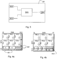
- Fig. 3 illustrates a block diagram of a conversion device 301 which for instance can be used as conversion device 203 in Fig. 2 .
- the conversion device 301 in this particular embodiment consists of two input connectors 302 and 303, an output connector 304 and a processing module 305 which interconnects the input connectors 302 and 303 to the output connector 304.
- the processing module 305 can be made up out of a buffer wherein input from either inputs 302 and 303 is stored until the input is sent to the output 304.
- the conversion device 301 may also contain an external switch to select on one of the inputs 302 and 303 and then the conversion device 301 accepts data from that input.
- Such a basic version can be used for instance in systems where the devices connected to the conversion module are able to send data in the appropriate format for the device connected to the output 304.
- the conversion device may contain a number of external buttons or switches which can be used to send instructions to the cutting device. These buttons or switches may be similar to buttons and switches found on the control panel of a cutting device such as a button to move on to the next step in a sequence, to stop the process, etc.
- a press on the emergency stop button should be accepted by the cutting device over any other instruction from any other control device or control module.
- This can be achieved by having a processor in the conversion device 301 which is able to detect the input signal and transmit the signals of the highest priority to the cutting device first.
- any signal from the inputs 302 and 303 may be relayed to the output 304 and the cutting machine is able to prioritize certain instructions over other instructions.
- the processing module 305 can contain a processor and a memory with instructions for the processor or a microcontroller with instructions embedded thereon.
- the instructions for the processor or microcontroller can be used to convert instructions received via either input 302 or 303 into a format or syntax that can be processed by the device connected to the output 304.
- the instructions obtained from a cutting device controller may be to cut a rip in three pieces of different sizes and may specify those sizes.
- the conversion module can convert this into absolute or relative coordinates for each cut and provide these positions to the device connected to output 304.
- the conversion device 301 may also be able to provide feedback to another input in which case inputs 302 and 303 can be considered as two-way interfaces.
- the conversion device may also send a signal to the computer 204 informing the computer of the desire to move on to the next step.
- the instructions to be executed by the processor or microcontroller can either define how the conversions are done, for instance by extracting the measurements from a cut instruction or the instructions may be linked to a conversion table wherein an instruction in one format is listed together with the same instruction in another format or syntax.
- the processor or microcontroller are able to analyse an incoming instruction and send out a corresponding instruction that can be executed by the device connected to the output 304.
- Both the inputs 302 and 303 can be made up out of various kinds of connectors.
- the inputs may be of the same kind of connector or may be of a different kind of connector.
- the input 302 can be of a type which is used to connect a control panel to a cutting device
- input 303 can be of a more generic type that is supported by various computers such as an Universal Serial Bus connector, a Serial line connector, a Firewire or IEEE 1394 connector, an RJ-45 or an RJ-11 connector, etc.
- the connector may also be a keyboard and/or mouse connector, in order to connect an external keyboard and/or mouse to a cutting device.
- the connectors may also be made up out of two parts, one part which is fixed to the housing of the conversion device 301 and one part which can be removed from the conversion device 301. This way it is possible to change the physical connectors available on the conversion device 301 by replacing the removable part by another type.
- the part connected to the housing may be made up out of a proprietary connector and the removable part may feature the same proprietary connector on one side and an USB connector on the other side.
- a second removable part may feature the proprietary connector on one side and an IEEE 1394 connector on the other side. This way, it is possible to have both an USB connector or an IEEE 1394 connector without needing an additional conversion device or a different conversion device.
- Changeable connectors may however need support in the processing module 305 and the removable parts may need some internal electronics to adapt signal levels from various specifications to a uniform signal level that is used within the conversion device. Of course, a similar approach can also be used on the output connector.
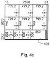
- Fig. 4a illustrates the initial cutting plan or layout for a board of 2500mm wide and 2070mm high.
- the layout consists of several rips which are further divided into several pieces.
- the layout as shown in Fig. 4a is not optimal.
- the rip from which the pieces indicated by 401 are to be cut is narrow and the final cut of that rip into the individual parts 401 is difficult to cut because the narrow side of the rip with parts 401 has to be placed into the clamps of the cutting device.
- the layout of Fig. 4a however has three more pieces at 402 which are the same as the two pieces at 401. The small rips in 401 can be left without doing the second level cuts.
- Fig. 4b wherein the five equal pieces are grouped at 403. In 403, all of the similar pieces with a narrow width are placed below each other. If the boards with these five parts is cut from the rip of 536 wide, the final cut of that part into the five pieces is along the long side of the pieces. In other words, the orientation of the final cut for pieces 401 from 4a is altered into an orientation which is more convenient to cut, the longest side. The waste at the bottom of 403 is needed in order to clamp the part in the cutting device to obtain the five narrow strips.
- the more optimal layout can also be split as far as the cutting sequence is concerned as shown in Fig.
- a large part 404 is cut from the last rip of the board.
- the large part 404 can then be re-cut as shown as 403 in Fig. 4b after the application of edge banding on the block 404 left and right.
- edge banding may result in rips or pieces which can no longer be obtained from the same board.
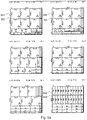
- Fig. 5a and 5b show a number of layouts which have to be cut in order to build the cupboards for a kitchen.
- Each individual layout is characterized by a number of parameters which are shown above the layout.
- the first layout is characterized by "Lay#: 1(93.53%) 16 Mel White Qty: 1".
- the Lay #: 1 represents the number of the layout which in this particular case is 1.
- the percentage indicated after the layout number between brackets is the amount of the board that is used. In this particular example, 93.53% of the board is used and only 6.47% is waste material which can be discarded.
- the waste material is indicated on the layout via a hashing.
- 16 Mel White is an identification of the type of material from which the layout has to be cut.
- the layout is cut from a board with a thickness of 16mm and a White Melamin colour.
- the Qty: 1 indicates the quantity of the board or in other words the amount of times a particular pattern is needed.
- Each of the other layouts has similar markings to indicate their number, the percentage of board used, the material and the number of boards. Furthermore, on each layout, the numbers indicate the length of a side of a part, rip or board in millimetres.
- the first layout is cut from a board with a total dimension of 2070mm x 2500mm. Within certain parts of the layouts shown in Fig. 5a and 5b , a small square is shown with one or more letters around it.
- the square represents the part itself and the letters indicate which type of finishing or edge banding that is required on that side of the part. For instance an 'm' indicates melamin and a 'p' indicates a PVC edge. Similar markings are used in Fig. 1 , Fig. 4a - 4c to indicate the size of the boards, rips or parts.
- Layouts 1 and 2 both contain two rips 501 from which three pieces of 749,2mm x 799,2 mm have to be cut. Since both layouts are cut from the same kind of boards, 16 Mel White or even when cut from different kinds of boards, it is possible to stack these boards even if certain restrictions apply such as no stacking of boards or rips of different materials or with a different thickness. By stacking all the rips 501 from layout 1 and layout 2, it is possible to cut the four rips 501 into the respective smaller parts simultaneously. This means that they are cut as one stack rather than rip by rip.
- Layout 6 contains two rips 502 which are to be cut into twelve equal pieces and layout 8 contains a single rip 502 which is to be cut into the same twelve equal pieces. It is thus possible to retain the rips 502 from layout 6 in storage until the rip 502 from layout 8 has been cut and then those three rips 502 can be stacked before they are cut into the twelve equal pieces simultaneously. Layouts 6 and 8 each have to be cut twice, it is therefore possible to stack even more rips up to a total of six rips if the cutting machine can handle a stack of that size otherwise several stacks may be aligned next to each other. Cutting the rip 502 from layout 6 into twelve identical pieces takes 11 cuts.
- both layouts 10 and 11 can be stacked to the total of five boards. All first rip widths are the same (667,2mm and 667,2mm and 700mm) and the two first rips 504 are cut together and the last rips 505 and 506 are cut independently which means that except for one rip cutting, the two stacks are cut as one stack.
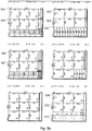
- Fig. 6 illustrates the cutting of layouts 10 which is needed three times and 11 which is needed two times in more detail
- 601 is a representation of the first level cuts that are cut from a stack of 5 boards.
- two rips of equal width (667; 2mm) are shown as 602 and the third rip is of different width (700mm) and is shown as 603.
- the rips of equal size can then be further cut into the smaller pieces 604 (750mm) as two stacks of 5 rips high which are aligned next to each other and cut simultaneously.
- the third rip of layout 10 and layout 11 cannot be combined for cutting as their last level cuts are different.
- layouts 7 and 9 are nearly identical.
- the top two rips 504 and 505 of layout 7 are equal to each other and the top two rips 506 and 507 of layout 9 are equal to each other. Because the top two rips of layouts 7 504 and 505 and 9 506 and 507 have the same width, it is possible to interchange rips between layout 7 and 9.
- the cutting of layouts 7 and 9 can be optimized by placing the second rip 507 of layout 9 in the place of the first rip 504 of layout 7 and vice versa. This way, layout 7 and layout 9 are identical and the boards can be stacked from the start.
- layouts 7, 9 and 12 Another example is to combine layouts 7, 9 and 12. By rotating the parts of the top two rips 508 and 509 of layout 12, these rips become identical to the top two rips of layouts 7 504 and 505 and of layout 9 506 and 507 without the small parts at the end of each rip. If layout 12 is then cut according to layout 7 or 9, which can be optimized as described above or not, some excess small parts are created. However, it may be acceptable that such parts are discarded in which case layouts 7, 9 and 12 can be combined. This example illustrates that even the current cutting level does not have to be identical when waste 510is available. The subsequent levels are not identical either, but layout 12 has waste which can be turned into excess parts. The subsequent levels of layouts 7, 9 and 12 can thus be processed simultaneously.
- the cutting plans as shown in Fig. 5a and 5b can be stored in a graphical representation, similar to the representation which is shown in the figures.
- a graphical representation can be used either for the initial cutting layout or for an optimized cutting layout.
- processing of graphical layouts is difficult to achieve and therefore an alphanumerical storage of the layout may be preferred.
- Such an alphanumeric storage is a representation of the layouts as a series of numerical values and commands or instructions. For instance, a board of 3000mm x 4500mm can be drawn or can be stored as a node in a tree with a length and a width value.
- Such a node may have one or more sub-nodes which represents the rips to be cut from the board, each having a length and a width.
- each node or sub-node may also contain one or more commands. Such a command can be cut, store, stack, etc but may also be a jump to another node, sub-node or command.
- the sub-nodes may themselves also contain a number of sub-nodes which make up the parts of the rip.
- a tree representation can be made of a board with rips and parts. Stacking may be more convenient by jumping from one rip to another rip via a jump command in order to obtain both rips without waiting for other rips that are in between the two rips.
- An alternative to the tree structure is the of data files such as XML files wherein each board is defined by a set of tags with the dimensions and characteristics as parameters of that tag.
- a rip is also defined as a set of parameters with characteristics and dimensions set as parameters of the tags and also the parts can be stored similarly.
- the part tags can be nested within rip tags, which in turn can be nested within board tags.
- Cutting machines always handle patterns in a three structure way, level by level, with the exception of ab ba cutting. If you have several books (stacks) of the same layout, then for each even book the rip sequence is inverted so that the last rip(s) from a previous book can be cut, for the second level, together with the first of the current book. This is only applied in automatic angular beam saws (2 axis) where books are mirrored so that the last rips from a book can be cut together with the first rips of the next book or small rips are kept aside in 1 buffer to be then cut all together.
Landscapes
- Engineering & Computer Science (AREA)
- Mechanical Engineering (AREA)
- Life Sciences & Earth Sciences (AREA)
- Wood Science & Technology (AREA)
- Forests & Forestry (AREA)
- General Factory Administration (AREA)
- Numerical Control (AREA)
- Warehouses Or Storage Devices (AREA)
Claims (6)
- Ablagesystem, Folgendes umfassend:- eine Ablage zum Halten von Resten von Tafeln und/ oder Restzuschnitten und/ oder Restzuschnitten, die nicht sofort in einem Ablauf mit den anderen geschnitten werden, um mit den künftigen geschnitten zu werden und die abzulegen sind;- ein Verfolgungssystem zum Registrieren einer manuellen Zugabe zur Ablage und einer manuellen Entfernung aus der Ablage von zumindest entweder den Tafeln und/ oder den Restzuschnitten und zum Registrieren der Stellen in der Ablage der Zugabe und der Entfernung, wobei das besagte Verfolgungssystem Kennungen zum Identifizieren der Tafeln oder Restzuschnitte umfasst, wobei die besagten Kennungen an den Stellen und an den Tafeln und/ oder Restzuschnitten angebracht werden, um deren Zuordnung in der Ablage wiederzufinden,dadurch gekennzeichnet, dass das System darüber hinaus ein Berechtigungssystem umfasst, das ein optisches, textuelles und/ oder akustisches Signal umfasst, um einem Anwender mitzuteilen, dass er berechtigt oder nicht berechtigt ist, zumindest eine bestimmte Tafel und/ oder einen Restzuschnitt an einer bestimmten Stelle aus der Ablage zu entfernen oder dort zumindest eine bestimmte Tafel und/ oder einen Restzuschnitt einzufügen.
- Ablagesystem nach Anspruch 1, wobei das Verfolgungssystem Kennungen umfasst, die durch die Verwendung eines Scanners erkannt werden können.
- Ablagesystem nach Anspruch 1, wobei das optische, textuelle und/ oder akustische Signal Lichter, Anzeigen und/ oder ein Audiosystem umfasst.
- Ablagesystem nach irgendeinem der vorhergehenden Ansprüche, eine automatisierte Ablage, oder Förderrollen oder Bänder oder eine Hedgehog-Ablage, oder eine Ablage basierend auf einer Anzahl an Ablageplätzen umfassend, wobei eine Person die Restzuschnitte und/ oder Tafeln von Hand platziert.
- Ablagesystem nach irgendeinem der vorhergehenden Ansprüche, darüber hinaus dadurch gekennzeichnet, dass die besagten Tafeln und/ oder Restzuschnitte und eine zweite Tafel aus einem oder mehreren der folgenden Materialien gefertigt sind:- eine oder mehrere Arten von Holz und/ oder Derivate davon- eine oder mehrere Arten von Metall und/ oder Nicht-Metall; und- eine oder mehrere Arten von Glas und/ oder Derivate davon.
- Verwendung eines Ablagesystems nach irgendeinem der vorhergehenden Ansprüche in einem System zum Steuern des Zuschnitts von Materialien.
Priority Applications (1)
| Application Number | Priority Date | Filing Date | Title |
|---|---|---|---|
| EP11174222.7A EP2377652B1 (de) | 2008-08-19 | 2009-07-14 | Lagersystem zum Halten von provisorischen Formaten von Brettern |
Applications Claiming Priority (3)
| Application Number | Priority Date | Filing Date | Title |
|---|---|---|---|
| EP20080014700 EP2156914A1 (de) | 2008-08-19 | 2008-08-19 | Steuersystem und damit verbundenes Schneidverfahren |
| EP11174222.7A EP2377652B1 (de) | 2008-08-19 | 2009-07-14 | Lagersystem zum Halten von provisorischen Formaten von Brettern |
| EP09777179.4A EP2326448B1 (de) | 2008-08-19 | 2009-07-14 | Steuersystem und damit verbundenes schneidverfahren |
Related Parent Applications (3)
| Application Number | Title | Priority Date | Filing Date |
|---|---|---|---|
| EP09777179.4A Division-Into EP2326448B1 (de) | 2008-08-19 | 2009-07-14 | Steuersystem und damit verbundenes schneidverfahren |
| EP09777179.4A Division EP2326448B1 (de) | 2008-08-19 | 2009-07-14 | Steuersystem und damit verbundenes schneidverfahren |
| EP09777179.4 Division | 2009-07-14 |
Publications (2)
| Publication Number | Publication Date |
|---|---|
| EP2377652A1 EP2377652A1 (de) | 2011-10-19 |
| EP2377652B1 true EP2377652B1 (de) | 2017-03-29 |
Family
ID=40205583
Family Applications (3)
| Application Number | Title | Priority Date | Filing Date |
|---|---|---|---|
| EP20080014700 Withdrawn EP2156914A1 (de) | 2008-08-19 | 2008-08-19 | Steuersystem und damit verbundenes Schneidverfahren |
| EP09777179.4A Revoked EP2326448B1 (de) | 2008-08-19 | 2009-07-14 | Steuersystem und damit verbundenes schneidverfahren |
| EP11174222.7A Revoked EP2377652B1 (de) | 2008-08-19 | 2009-07-14 | Lagersystem zum Halten von provisorischen Formaten von Brettern |
Family Applications Before (2)
| Application Number | Title | Priority Date | Filing Date |
|---|---|---|---|
| EP20080014700 Withdrawn EP2156914A1 (de) | 2008-08-19 | 2008-08-19 | Steuersystem und damit verbundenes Schneidverfahren |
| EP09777179.4A Revoked EP2326448B1 (de) | 2008-08-19 | 2009-07-14 | Steuersystem und damit verbundenes schneidverfahren |
Country Status (7)
| Country | Link |
|---|---|
| US (2) | US20110196527A1 (de) |
| EP (3) | EP2156914A1 (de) |
| CN (1) | CN102186613A (de) |
| BR (1) | BRPI0912911A2 (de) |
| ES (1) | ES2627578T3 (de) |
| RU (2) | RU2011108964A (de) |
| WO (1) | WO2010020310A1 (de) |
Families Citing this family (27)
| Publication number | Priority date | Publication date | Assignee | Title |
|---|---|---|---|---|
| EP2156914A1 (de) | 2008-08-19 | 2010-02-24 | Arnout De Lille | Steuersystem und damit verbundenes Schneidverfahren |
| US8359116B2 (en) * | 2009-09-11 | 2013-01-22 | Sap Ag | Production management system |
| FR2951976B1 (fr) * | 2009-11-02 | 2012-02-10 | Salm Sas | Dispositif de decoupe de panneaux |
| BE1019141A3 (nl) * | 2011-04-26 | 2012-03-06 | Lille Arnout De | Systeem en werkwijze voor het gecontroleerd snijden van platen. |
| US10505751B2 (en) * | 2011-08-25 | 2019-12-10 | Siemens Industry, Inc. | Synergistic interface system for a building network |
| CN102945018A (zh) * | 2011-11-22 | 2013-02-27 | 深圳众为兴技术股份有限公司 | 一种切割排序系统 |
| TW201421959A (zh) * | 2012-11-30 | 2014-06-01 | Foxnum Technology Co Ltd | 數控裝置管理系統及方法 |
| CN103197610B (zh) * | 2013-04-03 | 2016-03-16 | 达瑞建筑机械(上海)有限公司 | 具有结合工厂管理系统功能的数控金属材料裁剪设备 |
| JP6088478B2 (ja) * | 2014-10-27 | 2017-03-01 | ファナック株式会社 | テーブル形式データによる運転を行う数値制御装置 |
| US11569069B2 (en) | 2015-02-06 | 2023-01-31 | Applied Materials, Inc. | 3D printed chamber components configured for lower film stress and lower operating temperature |
| DE102015003811A1 (de) * | 2015-03-24 | 2016-09-29 | Ima Klessmann Gmbh Holzbearbeitungssysteme | Vorrichtung und Verfahren zur Bearbeitung plattenförmiger Werkstücke |
| WO2016181734A1 (ja) * | 2015-05-11 | 2016-11-17 | 村田機械株式会社 | 自動運転機器システム、非常停止端末、及び操作端末の制御方法 |
| FR3055718A1 (fr) * | 2016-09-07 | 2018-03-09 | Saint-Gobain Glass France | Procede et dispositif d'optimisation d'un plan de decoupe par guillotine de pieces de verre |
| DE102016014682A1 (de) * | 2016-12-09 | 2018-06-14 | Ima Klessmann Gmbh Holzbearbeitungssysteme | Verfahren und Vorrichtung zum Aufteilen von plattenförmigen Werkstücken |
| DE102017103867A1 (de) * | 2017-02-24 | 2018-08-30 | Homag Plattenaufteiltechnik Gmbh | Verfahren zum Betreiben einer Werkzeugmaschine, insbesondere einer Plattenbearbeitungsanlage zum Bearbeiten plattenförmiger Werkstücke, sowie Werkzeugmaschine |
| DE202017101710U1 (de) * | 2017-03-23 | 2018-06-26 | Wilhelm Altendorf Gmbh & Co. Kg | Ablagesteuerung für Sägemaschinen |
| DE102017121956A1 (de) * | 2017-09-21 | 2019-03-21 | Homag Plattenaufteiltechnik Gmbh | Verfahren zum Bearbeiten von Werkstücken, Computerprogrammprodukt, sowie Werkstückbearbeitungsanlage |
| BE1025225B1 (nl) * | 2017-11-14 | 2018-12-06 | Metaalwerken Pamo Nv | Werkwijze en inrichting voor het vervaardigen van metalen constructies vanuit metalen platen en/of profielen en verkregen metalen constructie |
| CN108255138A (zh) * | 2017-12-06 | 2018-07-06 | 洛阳兰迪玻璃机器股份有限公司 | 一种玻璃深加工连线控制方法 |
| IT201900013566A1 (it) * | 2019-07-31 | 2021-01-31 | Scm Group Spa | Macchina perfezionata per la lavorazione di pannelli, in legno e simili, e relativo metodo di funzionamento. |
| EP3904025A1 (de) * | 2020-04-29 | 2021-11-03 | IMA Schelling Austria GmbH | Verfahren zum zersägen zumindest einer platte |
| CN112474404A (zh) * | 2021-01-12 | 2021-03-12 | 江苏南洋中京科技有限公司 | 一种锻件原材料锯槽机用筛选装置 |
| CN113213745B (zh) * | 2021-03-24 | 2022-09-27 | 重庆惠科金渝光电科技有限公司 | 一种切割机及其切割方法 |
| DE102021110333A1 (de) * | 2021-04-22 | 2022-10-27 | Homag Plattenaufteiltechnik Gmbh | Vorbereitungsverfahren zum Vorbereiten der Aufteilung von mindestens zwei Werkstücken, Computerprogrammprodukt, computerlesbares Speichermedium, sowie Plattenaufteilanlage |
| CN113478632B (zh) * | 2021-06-22 | 2022-11-22 | 新乡北新建材有限公司 | 一种用于在线更换石膏板产品规格的处理调整系统及方法 |
| CN113695240B (zh) * | 2021-08-17 | 2023-05-16 | 池州市九华明坤铝业有限公司 | 一种基于图像检测的多孔零件批量检测设备 |
| IT202100033092A1 (it) * | 2021-12-30 | 2023-06-30 | Scm Group Spa | Metodo perfezionato per il taglio di pezzi. |
Citations (7)
| Publication number | Priority date | Publication date | Assignee | Title |
|---|---|---|---|---|
| DE9301327U1 (de) | 1993-02-01 | 1993-05-13 | Zambelli-Stahlmoebel-Gmbh & Co., 8396 Wegscheid, De | |
| DE19600348A1 (de) | 1996-01-08 | 1997-07-10 | Lewecke Gmbh Maschbau | Regalanlage für Platten |
| EP0891847A2 (de) | 1997-05-23 | 1999-01-20 | SCM GRoup Autec Division S.p.A. | Anlage zum Bestimmen und Herstellen von Möbelpaneelen aus Holz |
| DE20111933U1 (de) | 2001-07-12 | 2002-11-21 | Bellheimer Metallwerk Gmbh | Lagersystem mit Zugriffskontrollsystem |
| DE10139715A1 (de) | 2001-08-13 | 2003-02-27 | Hegla Fahrzeug Und Maschb Gmbh | Verfahren und Vorrichtung zum Bearbeiten von Glastafeln |
| US20080183327A1 (en) | 2007-01-26 | 2008-07-31 | Danelski Darin L | Picking System with Pick Verification |
| EP1990150A1 (de) | 2007-05-09 | 2008-11-12 | Weeke Bohrsysteme GmbH | Bearbeitungsmaschine |
Family Cites Families (30)
| Publication number | Priority date | Publication date | Assignee | Title |
|---|---|---|---|---|
| US3844426A (en) * | 1970-09-10 | 1974-10-29 | J Campbell | Method for cutting panels |
| US4185672A (en) * | 1974-02-06 | 1980-01-29 | Reed Ltd. | Integrated tree processing mill |
| IT1069913B (it) * | 1976-09-20 | 1985-03-25 | Giben Impianti Spa | Apparato per l accorciamento di pacchi di pannelli prima del loro inserimento in un qualsiasi ciclo di sezionatura |
| AT382548B (de) * | 1980-05-21 | 1987-03-10 | Schelling & Co | Einrichtung zum buntaufteilen von plattenfoermigen werkstuecken |
| US4509123A (en) * | 1983-01-06 | 1985-04-02 | Vereen William J | Automated tracking process for manufacturing and inventory |
| JPS6093511A (ja) * | 1983-10-27 | 1985-05-25 | Fanuc Ltd | フォーマット変換インタフェース装置 |
| AT390026B (de) | 1986-11-11 | 1990-03-12 | Schelling & Co | Vorrichtung zum buntaufteilen von plattenfoermigen werkstuecken |
| EP0376918B1 (de) * | 1988-12-30 | 1995-03-29 | Gebr. Linck Maschinenfabrik "Gatterlinck" GmbH & Co. KG | Verfahren und Vorrichtung zur Herstellung von Holzlamellen aus Schnittholz |
| US5251142A (en) * | 1990-12-14 | 1993-10-05 | Digital Cutting Systems, Inc. | Rip fence of table saw which may be positioned by computer control |
| US5099896A (en) * | 1991-04-24 | 1992-03-31 | Harvey Industries, Inc | Rotary board pick/store/place method and apparatus |
| EP0620528B2 (de) * | 1993-04-10 | 2001-10-31 | Christoph Schausten | Verfahren zur Lagerung von Stückgut und Vorrichtung zur Durchführung des Verfahrens |
| US6377864B1 (en) | 1994-06-16 | 2002-04-23 | Finn-Power International, Inc. | System and method of flexibly sorting and unloading finished parts during part manufacturing process |
| IT1298389B1 (it) * | 1997-12-24 | 2000-01-05 | Giben Impianti Spa | Macchina sezionatrice per il taglio di pannelli e relativo metodo di taglio. |
| DE19812377A1 (de) * | 1998-03-20 | 1999-09-23 | Siemens Ag | System für den automatisierten Betrieb eines Langgutlagers |
| DE19935318A1 (de) * | 1999-07-28 | 2001-02-08 | Schneider Automation Gmbh | Produktionssystem |
| DE10109007B4 (de) | 2001-02-23 | 2006-03-02 | Löffler Maschinenbau GmbH | Kreissägeanlage |
| DE20107572U1 (de) * | 2001-05-03 | 2001-07-12 | Paul Ott Gmbh Lambach | Vorrichtung zur Herstellung von rechteckigen Möbelplatten mit angeleimter Kante |
| US20030192412A1 (en) * | 2002-04-10 | 2003-10-16 | Siempelkamp Handling Systeme Gmbh & Co. | Device for marking and analyzing defects in a system for cutting boards to size made of wood at least in part |
| US20060086222A1 (en) * | 2002-08-20 | 2006-04-27 | Dick Spencer B | Carriage and rail assembly for a linear positioning system |
| US7406190B2 (en) * | 2003-07-24 | 2008-07-29 | Lucidyne Technologies, Inc. | Wood tracking by identification of surface characteristics |
| US20070023193A1 (en) * | 2003-09-17 | 2007-02-01 | King Roy D | Inventory control system |
| US20050262977A1 (en) * | 2004-05-25 | 2005-12-01 | Wilkerson Steven J | Machine and process for optimizing truss cutting |
| DE102005010795A1 (de) * | 2005-03-07 | 2006-09-14 | Häussermann GmbH & Co. KG | Anordnung und Verfahren zum Sortieren von Holz-Halbwaren |
| JP2006293744A (ja) * | 2005-04-12 | 2006-10-26 | Fanuc Ltd | プログラム変換装置 |
| US7630791B2 (en) * | 2005-12-09 | 2009-12-08 | CareFusion 303 Inc. | System and method for storing items and tracking item usage |
| DE102006002403A1 (de) * | 2006-01-18 | 2007-07-19 | Homag Holzbearbeitungssysteme Ag | System zum Herstellen von plattenförmigen Werkstücken |
| US8010216B2 (en) * | 2006-05-18 | 2011-08-30 | Roise Geoffrey J | System and method for cutting-stock optimization across schedules and batches |
| US7826921B2 (en) * | 2006-09-29 | 2010-11-02 | Tin, Inc. | Building lumber package assembly method and system |
| US7856465B2 (en) * | 2006-12-21 | 2010-12-21 | Intel Corporation | Combined fast fourier transforms and matrix operations |
| EP2156914A1 (de) | 2008-08-19 | 2010-02-24 | Arnout De Lille | Steuersystem und damit verbundenes Schneidverfahren |
-
2008
- 2008-08-19 EP EP20080014700 patent/EP2156914A1/de not_active Withdrawn
-
2009
- 2009-07-14 CN CN2009801415659A patent/CN102186613A/zh active Pending
- 2009-07-14 EP EP09777179.4A patent/EP2326448B1/de not_active Revoked
- 2009-07-14 RU RU2011108964/02A patent/RU2011108964A/ru not_active Application Discontinuation
- 2009-07-14 US US13/059,895 patent/US20110196527A1/en not_active Abandoned
- 2009-07-14 BR BRPI0912911A patent/BRPI0912911A2/pt not_active IP Right Cessation
- 2009-07-14 ES ES11174222.7T patent/ES2627578T3/es active Active
- 2009-07-14 WO PCT/EP2009/005109 patent/WO2010020310A1/en active Application Filing
- 2009-07-14 EP EP11174222.7A patent/EP2377652B1/de not_active Revoked
-
2014
- 2014-02-18 US US14/182,943 patent/US20140163719A1/en not_active Abandoned
- 2014-02-25 RU RU2014106907/02A patent/RU2014106907A/ru not_active Application Discontinuation
Patent Citations (8)
| Publication number | Priority date | Publication date | Assignee | Title |
|---|---|---|---|---|
| DE9301327U1 (de) | 1993-02-01 | 1993-05-13 | Zambelli-Stahlmoebel-Gmbh & Co., 8396 Wegscheid, De | |
| DE19600348A1 (de) | 1996-01-08 | 1997-07-10 | Lewecke Gmbh Maschbau | Regalanlage für Platten |
| DE19600348C2 (de) | 1996-01-08 | 2001-11-22 | Lewecke Maschb Gmbh | Regalanlage für Platten |
| EP0891847A2 (de) | 1997-05-23 | 1999-01-20 | SCM GRoup Autec Division S.p.A. | Anlage zum Bestimmen und Herstellen von Möbelpaneelen aus Holz |
| DE20111933U1 (de) | 2001-07-12 | 2002-11-21 | Bellheimer Metallwerk Gmbh | Lagersystem mit Zugriffskontrollsystem |
| DE10139715A1 (de) | 2001-08-13 | 2003-02-27 | Hegla Fahrzeug Und Maschb Gmbh | Verfahren und Vorrichtung zum Bearbeiten von Glastafeln |
| US20080183327A1 (en) | 2007-01-26 | 2008-07-31 | Danelski Darin L | Picking System with Pick Verification |
| EP1990150A1 (de) | 2007-05-09 | 2008-11-12 | Weeke Bohrsysteme GmbH | Bearbeitungsmaschine |
Non-Patent Citations (15)
| Title |
|---|
| "Highlights TLF Lagersteuerung", BARSTEDT HANDLINGSYSTEME, 6 June 2007 (2007-06-06), XP055620526 |
| ARNE MÖMESHEIM: "Kauf einer Plattenaufteilsäge oder -anlage ist kein Kauf von der Stange", April 2007 (2007-04-01), KG, pages 24 - 25, XP055620543 |
| DE KOSTER R. ET AL.: "Design and control of warehouse order picking: a literature review", RSM ERASMUS UNIVERSITY, 2007, pages 1 - 30, XP055448708 |
| GLEIBNER H. ET AL.: "LOGISTIK", 2008, article "5.5 kommissionierung und umschlag", pages: 121 - 124, XP055448699 |
| HENRY MÜLLER: "TLF Powercontrol Produktinformation", 21 June 2007 (2007-06-21), pages 1 - 72, XP055620534 |
| JÖRG TIEDEMANN: "Intelligente Transport- und Handlingssysteme im Plattenzuschnitt", HOB, September 2005 (2005-09-01), pages 47 - 52, XP055447297 |
| JÖRG TIEDEMANN: "Intelligente Transport- und Handlingssysteme im Plattenzuschnitt", HOB, vol. 2005, no. 09, 1 September 2005 (2005-09-01), pages 47 - 52 * |
| JÖRG TIEDEMANN: "Offenes Steuerungssystem - Synthese von Plattensäge und Lager", HOB, vol. 2000, no. 1-2, 1 January 2000 (2000-01-01), pages 62 - 67 * |
| MARTIN KRESS: "Gut Ding will Weile haben - auch der Kunde sollte sich Zeit gönnen", March 2008 (2008-03-01), KG, pages 20, XP055620548 |
| MULCAHY D.E. ET AL.: "Order-Fulfillment and Across-the-Dock Concepts , Design, and Operations Handbook", 2004, article "Order-Fulfillment Concepts , Design and operations", pages: 132-136,329,366 - 367, XP055448696 |
| SCHELLING ANLAGENBAU GMBH: "MCS Modular control System ( Modulares Steuerungs-System) Resteverwaltung XBob", 20 July 2006 (2006-07-20), pages 1 - 11, XP055447335 |
| TIEDEMANN: "Plattenaufteiltechnik", September 2005, article "Intelligente Transport- und Handlings-systeme im Plattenzuschnitt", pages: 46 - 52, XP055448670 |
| TIEDEMANN: "TLF 21 Ein/Ausstapelanlae Lagersoftware TLF Powercontrol", BARGSTEDT, 6 June 2007 (2007-06-06), pages 56pp, XP055620515 |
| TOMPKINS J.A. ET AL.: "The Warehouse Management Handbook", 1998, article "chapter 20", pages: 478, XP055448691 |
| ZEILHOFER-FICKER: "Moderne Kommissionierungstechniken", 2004, ISBN: 9783737910361, article "Moderne Kommissionierungstechniken", XP055448674 |
Also Published As
| Publication number | Publication date |
|---|---|
| US20110196527A1 (en) | 2011-08-11 |
| ES2627578T3 (es) | 2017-07-28 |
| WO2010020310A1 (en) | 2010-02-25 |
| EP2377652A1 (de) | 2011-10-19 |
| EP2326448A1 (de) | 2011-06-01 |
| EP2326448B1 (de) | 2015-03-04 |
| RU2014106907A (ru) | 2015-08-27 |
| EP2156914A1 (de) | 2010-02-24 |
| RU2011108964A (ru) | 2012-09-27 |
| US20140163719A1 (en) | 2014-06-12 |
| CN102186613A (zh) | 2011-09-14 |
| BRPI0912911A2 (pt) | 2016-07-05 |
Similar Documents
| Publication | Publication Date | Title |
|---|---|---|
| EP2377652B1 (de) | Lagersystem zum Halten von provisorischen Formaten von Brettern | |
| AU2009239878B2 (en) | Method and arrangement for manufacturing packages in a digitally controlled process | |
| CN101875170B (zh) | 集装箱门板的生产方法及生产系统 | |
| CN105549536A (zh) | 一种控制大板套裁的方法及系统 | |
| CN111496933A (zh) | 一种高速电脑裁板锯的控制系统及工作方法 | |
| CN104786270A (zh) | 一种新型高效智能裁板的生产工艺 | |
| CN111452149A (zh) | 一种电脑裁板锯的控制系统及工作方法 | |
| US9933777B2 (en) | Methods for schedule optimization sorting of dry end orders on a corrugator to minimize short order recovery time | |
| CN102514234B (zh) | 自动横移机构的薄刀分纸压线机的调整系统 | |
| EP2090394B1 (de) | Verfahren zum Schneiden einer Platte | |
| BE1019141A3 (nl) | Systeem en werkwijze voor het gecontroleerd snijden van platen. | |
| CN113199249B (zh) | 一种幕墙长杆料加工生产线及其加工方法 | |
| CN212421641U (zh) | 木工机台加工系统 | |
| US20060293622A1 (en) | System and method for making braces for dies | |
| CN111618969A (zh) | 木工机台加工系统 | |
| EP0985990B1 (de) | Bearbeitungsvorrichtung mit Laserstrahlen | |
| CN208773806U (zh) | 一种新型数控木工铣边钻孔机 | |
| CN203526944U (zh) | 自动麻将桌用铝条生产机器人 | |
| CN215238060U (zh) | 卧式自动铣销工装 | |
| WO1994025909A1 (en) | Numeric controller of machine tool and method of generating numeric control program | |
| JP2878122B2 (ja) | ネスティング用データ作成方法および板部品の製造方法 | |
| CN205766600U (zh) | 一种实木家具多工序一次成型装置 | |
| CN113733250A (zh) | 电脑裁板锯的控制系统及其工作方法 | |
| KR101731877B1 (ko) | 선박의 앵글에 사용되는 컬러 플레이트의 공통부재화 방법 | |
| MXPA06003923A (es) | Sistema y metodo para hacer refuerzos para dados |
Legal Events
| Date | Code | Title | Description |
|---|---|---|---|
| AC | Divisional application: reference to earlier application |
Ref document number: 2326448 Country of ref document: EP Kind code of ref document: P |
|
| AK | Designated contracting states |
Kind code of ref document: A1 Designated state(s): AT BE BG CH CY CZ DE DK EE ES FI FR GB GR HR HU IE IS IT LI LT LU LV MC MK MT NL NO PL PT RO SE SI SK SM TR |
|
| AX | Request for extension of the european patent |
Extension state: AL BA RS |
|
| PUAI | Public reference made under article 153(3) epc to a published international application that has entered the european phase |
Free format text: ORIGINAL CODE: 0009012 |
|
| 17P | Request for examination filed |
Effective date: 20120419 |
|
| TPAC | Observations filed by third parties |
Free format text: ORIGINAL CODE: EPIDOSNTIPA |
|
| 17Q | First examination report despatched |
Effective date: 20141110 |
|
| GRAP | Despatch of communication of intention to grant a patent |
Free format text: ORIGINAL CODE: EPIDOSNIGR1 |
|
| INTG | Intention to grant announced |
Effective date: 20161221 |
|
| GRAS | Grant fee paid |
Free format text: ORIGINAL CODE: EPIDOSNIGR3 |
|
| GRAA | (expected) grant |
Free format text: ORIGINAL CODE: 0009210 |
|
| AC | Divisional application: reference to earlier application |
Ref document number: 2326448 Country of ref document: EP Kind code of ref document: P |
|
| AK | Designated contracting states |
Kind code of ref document: B1 Designated state(s): AT BE BG CH CY CZ DE DK EE ES FI FR GB GR HR HU IE IS IT LI LT LU LV MC MK MT NL NO PL PT RO SE SI SK SM TR |
|
| REG | Reference to a national code |
Ref country code: GB Ref legal event code: FG4D |
|
| REG | Reference to a national code |
Ref country code: CH Ref legal event code: EP |
|
| REG | Reference to a national code |
Ref country code: AT Ref legal event code: REF Ref document number: 879294 Country of ref document: AT Kind code of ref document: T Effective date: 20170415 |
|
| REG | Reference to a national code |
Ref country code: IE Ref legal event code: FG4D |
|
| REG | Reference to a national code |
Ref country code: DE Ref legal event code: R096 Ref document number: 602009045158 Country of ref document: DE |
|
| REG | Reference to a national code |
Ref country code: NL Ref legal event code: FP |
|
| REG | Reference to a national code |
Ref country code: CH Ref legal event code: NV Representative=s name: MICHELI AND CIE SA, CH |
|
| REG | Reference to a national code |
Ref country code: ES Ref legal event code: FG2A Ref document number: 2627578 Country of ref document: ES Kind code of ref document: T3 Effective date: 20170728 |
|
| PG25 | Lapsed in a contracting state [announced via postgrant information from national office to epo] |
Ref country code: LT Free format text: LAPSE BECAUSE OF FAILURE TO SUBMIT A TRANSLATION OF THE DESCRIPTION OR TO PAY THE FEE WITHIN THE PRESCRIBED TIME-LIMIT Effective date: 20170329 Ref country code: HR Free format text: LAPSE BECAUSE OF FAILURE TO SUBMIT A TRANSLATION OF THE DESCRIPTION OR TO PAY THE FEE WITHIN THE PRESCRIBED TIME-LIMIT Effective date: 20170329 Ref country code: GR Free format text: LAPSE BECAUSE OF FAILURE TO SUBMIT A TRANSLATION OF THE DESCRIPTION OR TO PAY THE FEE WITHIN THE PRESCRIBED TIME-LIMIT Effective date: 20170630 Ref country code: FI Free format text: LAPSE BECAUSE OF FAILURE TO SUBMIT A TRANSLATION OF THE DESCRIPTION OR TO PAY THE FEE WITHIN THE PRESCRIBED TIME-LIMIT Effective date: 20170329 Ref country code: NO Free format text: LAPSE BECAUSE OF FAILURE TO SUBMIT A TRANSLATION OF THE DESCRIPTION OR TO PAY THE FEE WITHIN THE PRESCRIBED TIME-LIMIT Effective date: 20170629 |
|
| PG25 | Lapsed in a contracting state [announced via postgrant information from national office to epo] |
Ref country code: SE Free format text: LAPSE BECAUSE OF FAILURE TO SUBMIT A TRANSLATION OF THE DESCRIPTION OR TO PAY THE FEE WITHIN THE PRESCRIBED TIME-LIMIT Effective date: 20170329 Ref country code: LV Free format text: LAPSE BECAUSE OF FAILURE TO SUBMIT A TRANSLATION OF THE DESCRIPTION OR TO PAY THE FEE WITHIN THE PRESCRIBED TIME-LIMIT Effective date: 20170329 Ref country code: BG Free format text: LAPSE BECAUSE OF FAILURE TO SUBMIT A TRANSLATION OF THE DESCRIPTION OR TO PAY THE FEE WITHIN THE PRESCRIBED TIME-LIMIT Effective date: 20170629 |
|
| PG25 | Lapsed in a contracting state [announced via postgrant information from national office to epo] |
Ref country code: EE Free format text: LAPSE BECAUSE OF FAILURE TO SUBMIT A TRANSLATION OF THE DESCRIPTION OR TO PAY THE FEE WITHIN THE PRESCRIBED TIME-LIMIT Effective date: 20170329 Ref country code: RO Free format text: LAPSE BECAUSE OF FAILURE TO SUBMIT A TRANSLATION OF THE DESCRIPTION OR TO PAY THE FEE WITHIN THE PRESCRIBED TIME-LIMIT Effective date: 20170329 Ref country code: CZ Free format text: LAPSE BECAUSE OF FAILURE TO SUBMIT A TRANSLATION OF THE DESCRIPTION OR TO PAY THE FEE WITHIN THE PRESCRIBED TIME-LIMIT Effective date: 20170329 Ref country code: SK Free format text: LAPSE BECAUSE OF FAILURE TO SUBMIT A TRANSLATION OF THE DESCRIPTION OR TO PAY THE FEE WITHIN THE PRESCRIBED TIME-LIMIT Effective date: 20170329 |
|
| PGFP | Annual fee paid to national office [announced via postgrant information from national office to epo] |
Ref country code: IT Payment date: 20170731 Year of fee payment: 9 |
|
| PG25 | Lapsed in a contracting state [announced via postgrant information from national office to epo] |
Ref country code: PT Free format text: LAPSE BECAUSE OF FAILURE TO SUBMIT A TRANSLATION OF THE DESCRIPTION OR TO PAY THE FEE WITHIN THE PRESCRIBED TIME-LIMIT Effective date: 20170731 Ref country code: IS Free format text: LAPSE BECAUSE OF FAILURE TO SUBMIT A TRANSLATION OF THE DESCRIPTION OR TO PAY THE FEE WITHIN THE PRESCRIBED TIME-LIMIT Effective date: 20170729 Ref country code: PL Free format text: LAPSE BECAUSE OF FAILURE TO SUBMIT A TRANSLATION OF THE DESCRIPTION OR TO PAY THE FEE WITHIN THE PRESCRIBED TIME-LIMIT Effective date: 20170329 Ref country code: SM Free format text: LAPSE BECAUSE OF FAILURE TO SUBMIT A TRANSLATION OF THE DESCRIPTION OR TO PAY THE FEE WITHIN THE PRESCRIBED TIME-LIMIT Effective date: 20170329 |
|
| REG | Reference to a national code |
Ref country code: DE Ref legal event code: R026 Ref document number: 602009045158 Country of ref document: DE |
|
| PLBI | Opposition filed |
Free format text: ORIGINAL CODE: 0009260 |
|
| PLBI | Opposition filed |
Free format text: ORIGINAL CODE: 0009260 |
|
| PLAX | Notice of opposition and request to file observation + time limit sent |
Free format text: ORIGINAL CODE: EPIDOSNOBS2 |
|
| PG25 | Lapsed in a contracting state [announced via postgrant information from national office to epo] |
Ref country code: DK Free format text: LAPSE BECAUSE OF FAILURE TO SUBMIT A TRANSLATION OF THE DESCRIPTION OR TO PAY THE FEE WITHIN THE PRESCRIBED TIME-LIMIT Effective date: 20170329 |
|
| 26 | Opposition filed |
Opponent name: SCHELLING ANLAGENBAU GMBH Effective date: 20171222 Opponent name: HOMAG AUTOMATION GMBH Effective date: 20171222 |
|
| 26 | Opposition filed |
Opponent name: BIESSE S.P.A. Effective date: 20171229 |
|
| REG | Reference to a national code |
Ref country code: CH Ref legal event code: PL |
|
| REG | Reference to a national code |
Ref country code: NL Ref legal event code: MM Effective date: 20170801 |
|
| GBPC | Gb: european patent ceased through non-payment of renewal fee |
Effective date: 20170714 |
|
| REG | Reference to a national code |
Ref country code: IE Ref legal event code: MM4A |
|
| REG | Reference to a national code |
Ref country code: FR Ref legal event code: ST Effective date: 20180330 |
|
| PG25 | Lapsed in a contracting state [announced via postgrant information from national office to epo] |
Ref country code: LI Free format text: LAPSE BECAUSE OF NON-PAYMENT OF DUE FEES Effective date: 20170731 Ref country code: IE Free format text: LAPSE BECAUSE OF NON-PAYMENT OF DUE FEES Effective date: 20170714 Ref country code: GB Free format text: LAPSE BECAUSE OF NON-PAYMENT OF DUE FEES Effective date: 20170714 Ref country code: CH Free format text: LAPSE BECAUSE OF NON-PAYMENT OF DUE FEES Effective date: 20170731 Ref country code: NL Free format text: LAPSE BECAUSE OF NON-PAYMENT OF DUE FEES Effective date: 20170801 |
|
| PLAF | Information modified related to communication of a notice of opposition and request to file observations + time limit |
Free format text: ORIGINAL CODE: EPIDOSCOBS2 |
|
| PG25 | Lapsed in a contracting state [announced via postgrant information from national office to epo] |
Ref country code: SI Free format text: LAPSE BECAUSE OF FAILURE TO SUBMIT A TRANSLATION OF THE DESCRIPTION OR TO PAY THE FEE WITHIN THE PRESCRIBED TIME-LIMIT Effective date: 20170329 Ref country code: FR Free format text: LAPSE BECAUSE OF NON-PAYMENT OF DUE FEES Effective date: 20170731 |
|
| PG25 | Lapsed in a contracting state [announced via postgrant information from national office to epo] |
Ref country code: LU Free format text: LAPSE BECAUSE OF NON-PAYMENT OF DUE FEES Effective date: 20170714 |
|
| PLBB | Reply of patent proprietor to notice(s) of opposition received |
Free format text: ORIGINAL CODE: EPIDOSNOBS3 |
|
| PG25 | Lapsed in a contracting state [announced via postgrant information from national office to epo] |
Ref country code: MT Free format text: LAPSE BECAUSE OF NON-PAYMENT OF DUE FEES Effective date: 20170714 |
|
| PG25 | Lapsed in a contracting state [announced via postgrant information from national office to epo] |
Ref country code: HU Free format text: LAPSE BECAUSE OF FAILURE TO SUBMIT A TRANSLATION OF THE DESCRIPTION OR TO PAY THE FEE WITHIN THE PRESCRIBED TIME-LIMIT; INVALID AB INITIO Effective date: 20090714 Ref country code: MC Free format text: LAPSE BECAUSE OF FAILURE TO SUBMIT A TRANSLATION OF THE DESCRIPTION OR TO PAY THE FEE WITHIN THE PRESCRIBED TIME-LIMIT Effective date: 20170329 |
|
| PG25 | Lapsed in a contracting state [announced via postgrant information from national office to epo] |
Ref country code: IT Free format text: LAPSE BECAUSE OF NON-PAYMENT OF DUE FEES Effective date: 20180714 |
|
| REG | Reference to a national code |
Ref country code: AT Ref legal event code: UEP Ref document number: 879294 Country of ref document: AT Kind code of ref document: T Effective date: 20170329 |
|
| PG25 | Lapsed in a contracting state [announced via postgrant information from national office to epo] |
Ref country code: CY Free format text: LAPSE BECAUSE OF NON-PAYMENT OF DUE FEES Effective date: 20170329 |
|
| PGFP | Annual fee paid to national office [announced via postgrant information from national office to epo] |
Ref country code: ES Payment date: 20190822 Year of fee payment: 11 Ref country code: DE Payment date: 20190719 Year of fee payment: 11 |
|
| PG25 | Lapsed in a contracting state [announced via postgrant information from national office to epo] |
Ref country code: MK Free format text: LAPSE BECAUSE OF FAILURE TO SUBMIT A TRANSLATION OF THE DESCRIPTION OR TO PAY THE FEE WITHIN THE PRESCRIBED TIME-LIMIT Effective date: 20170329 |
|
| PGFP | Annual fee paid to national office [announced via postgrant information from national office to epo] |
Ref country code: BE Payment date: 20190718 Year of fee payment: 11 |
|
| PLAB | Opposition data, opponent's data or that of the opponent's representative modified |
Free format text: ORIGINAL CODE: 0009299OPPO |
|
| PGFP | Annual fee paid to national office [announced via postgrant information from national office to epo] |
Ref country code: AT Payment date: 20190722 Year of fee payment: 11 |
|
| R26 | Opposition filed (corrected) |
Opponent name: IMA SCHELLING AUSTRIA GMBH Effective date: 20171222 |
|
| REG | Reference to a national code |
Ref country code: DE Ref legal event code: R064 Ref document number: 602009045158 Country of ref document: DE Ref country code: DE Ref legal event code: R103 Ref document number: 602009045158 Country of ref document: DE |
|
| PG25 | Lapsed in a contracting state [announced via postgrant information from national office to epo] |
Ref country code: TR Free format text: LAPSE BECAUSE OF FAILURE TO SUBMIT A TRANSLATION OF THE DESCRIPTION OR TO PAY THE FEE WITHIN THE PRESCRIBED TIME-LIMIT Effective date: 20170329 |
|
| RDAF | Communication despatched that patent is revoked |
Free format text: ORIGINAL CODE: EPIDOSNREV1 |
|
| RDAG | Patent revoked |
Free format text: ORIGINAL CODE: 0009271 |
|
| STAA | Information on the status of an ep patent application or granted ep patent |
Free format text: STATUS: PATENT REVOKED |
|
| 27W | Patent revoked |
Effective date: 20200121 |
|
| REG | Reference to a national code |
Ref country code: FI Ref legal event code: MGE |
|
| REG | Reference to a national code |
Ref country code: AT Ref legal event code: MA03 Ref document number: 879294 Country of ref document: AT Kind code of ref document: T Effective date: 20200121 |