EP2377454B1 - Griff für einen Drahtkorb - Google Patents
Griff für einen Drahtkorb Download PDFInfo
- Publication number
- EP2377454B1 EP2377454B1 EP10401053.3A EP10401053A EP2377454B1 EP 2377454 B1 EP2377454 B1 EP 2377454B1 EP 10401053 A EP10401053 A EP 10401053A EP 2377454 B1 EP2377454 B1 EP 2377454B1
- Authority
- EP
- European Patent Office
- Prior art keywords
- handle
- wire
- assembled state
- final assembled
- base body
- Prior art date
- Legal status (The legal status is an assumption and is not a legal conclusion. Google has not performed a legal analysis and makes no representation as to the accuracy of the status listed.)
- Active
Links
Images


Classifications
-
- A—HUMAN NECESSITIES
- A47—FURNITURE; DOMESTIC ARTICLES OR APPLIANCES; COFFEE MILLS; SPICE MILLS; SUCTION CLEANERS IN GENERAL
- A47L—DOMESTIC WASHING OR CLEANING; SUCTION CLEANERS IN GENERAL
- A47L15/00—Washing or rinsing machines for crockery or tableware
- A47L15/42—Details
- A47L15/50—Racks ; Baskets
Definitions
- the invention relates to a handle for a wire basket, in particular the lower basket of a dishwasher, which can be moved in and out by a user into the loading area of a dishwasher.
- Wire baskets for dishwashers are generally designed in such a way that a user can pull them out of the dishwasher manually and push them into the dishwasher. For this purpose, the user grasps the wire basket on one of the wires or, in the case of higher-quality dishwashers, on a handle provided on the wire basket.
- Handles for wire baskets known from the prior art have the disadvantage that the connection of the handle to the wire basket has a play perceptible to the user.
- previously known handles do not achieve an optics and haptics that are appealing to the user, since they have visible and tactile bumps, which are caused, for example, by contours.
- the assembly of known handles is complex, since these handles consist of several parts and are fastened with separate fastening means.
- a handle for a wire basket known with a body consisting of two half-shells.
- the half-shells have wire receptacles designed to correspond to one another, by means of which a wire of the wire basket is received between them, It is the object of the invention to propose a handle for a wire basket, in particular the lower basket of a dishwasher, which can be installed in a simple manner while at the same time being more convenient to use.
- the invention proposes a handle with a base body consisting of two half-shells which, in the final assembled state, accommodate a wire of the wire basket without a gap between them, for which purpose the half-shells provide wire receptacles corresponding to one another, which are designed to be resilient.
- the handle according to the invention has a base body consisting of two half-shells. In the final assembled state, they take a wire from the wire basket between them without play. According to the invention, this is achieved in that the half-shells have wire receptacles that hold the wire in all six degrees of freedom store the room.
- the wire receptacles are designed to be resilient, so that in the final assembled state there is a spring tension between the base body on the one hand and the wire on the other hand.
- a handle designed in this way is advantageously arranged on the wire basket without play. Relative movement of the handle relative to the basket, which a user would perceive as "wobbling", is advantageously prevented.
- a force exerted by a user on the handle is transmitted directly to the wire basket and does not lead to "wobbling", “tipping” and / or twisting of the handle relative to the wire basket.
- a user perceives the wire basket with the handle according to the invention as a particularly high-quality product.
- the half-shells provide wire receptacles designed to correspond to one another.
- the geometric shape of the wire receptacles is designed to match the contour, in particular cross-sectional contour, of the wire.
- the wire receptacles are designed in the form of a part circle and enclose the received wire in the final assembled state.
- the half-shells can provide a wire holder for a wire or wire holders for two or more wires.
- the inventive design of a wire holder, distributed over two half-shells, advantageously enables a simplified assembly of the handle on the wire basket.
- the one half-shell and the other half-shell are joined together and connected to one another with the interposition of one or more wires.
- the wire receptacles are designed to be resilient. It can be provided that the material of the base body itself is resilient, so that the wire with the two half-shells forms an interference fit, the material of the base body itself serving as a spring and being under spring tension in the final assembled state. In particular, however, it can also be provided that the half-shells in the area of the wire receptacles essentially form a clearance fit with the wire, and spring elements are provided on the half-shells, which design the connection of the handle and the wire basket in the final assembled state without play.
- the choice of material for the half-shells is thus advantageously not restricted. It is particularly advantageous that possible manufacturing tolerances can be compensated for by the spring elements. In this way, more cost-effective production processes, for example the injection molding process, for producing the handle according to the invention are also possible, while the quality is perceived by a user to be increased.
- one of the wire receptacles of the handle according to the invention has a centering, which engages in a bead provided by the wire in the final assembled state.
- a wire is provided on the wire basket, which provides a bead into which a counterbearing engages in the final assembled state, for example in the form of a U-shaped or V-shaped element arranged on the handle, which can in particular also be designed as a spring element.
- the wire bead corresponding to this element can be formed by a U-shaped or two S-shaped bends in the wire.
- the position of the handle on the wire basket is advantageously determined by the centering.
- the handle does not have to be aligned with the wire basket, but rather that its position is already determined in terms of construction.
- Centering has another advantage.
- the element for centering forms a positive connection with the corresponding wire bead. Slipping of the handle in the direction of the longitudinal extent of the wire, ie relative displacement, is therefore not possible.
- the configuration of the centering as a spring element is particularly advantageous. In the final assembled state, the base body is supported under spring tension in the centering designed as a spring element with respect to the wire basket without play.
- the half-shells of the handle according to the invention have connecting elements which correspond to one another.
- Such connecting elements hold the two half-shells, to which at least one wire of the wire basket is interposed, connected in the final assembled state.
- Such connecting elements can, for example, provide a positive, non-positive and / or integral connection of the two half-shells in the final assembled state.
- the handle can be attached to one or more wires with a handle and fixed with the connecting elements.
- the correspondingly designed connecting elements of the two half-shells form a positive connection.
- the connecting elements can be formed by screws, bolts, rivets, push buttons, snap connections or the like.
- Such connecting elements advantageously provide a form-fitting connection that is easy to implement mechanically.
- the connecting elements of the two half-shells which correspond to one another form a snap-in connection.
- the connecting elements have an L-shaped projection on the shell side and a recess on the other shell side, the L-shaped projection forming a latching connection with the recess in the final assembled state. It is particularly advantageous that such connecting elements can be connected without a tool, and rather snap in by simply pressing the two half-shells together, which simplifies assembly.
- the half-shells have recesses which are designed such that the snap-in connection described by the recesses a suitable tool can be released by bending, pressing or the like.
- the handle can, if it should be necessary, be separated from the wire basket without being destroyed.
- the half-shells of the handle are designed to be pivotable relative to one another by means of a film hinge.
- the two half-shells can be connected to one another by a film hinge, but preferably by two or three film hinges.
- a film hinge is preferably formed in one piece with the two half-shells.
- the half-shells and the film hinge can be formed from the same material.
- the entire base body can thus be made from one piece.
- the film hinge is designed in such a way that the two half-shells can be pivoted relative to one another, in particular in such a way that they abut one another in a certain pivoting position.
- the connecting elements described lie corresponding to one another.
- the described connecting elements with an L-shaped projection and a corresponding recess in the described pivot position form the advantageous latching connection described.
- the base body can thus be placed with the one half-shell on the wire of a wire basket, and closed by pivoting the other half-shell around an axis of the film hinge with the at least one wire interposed, the connecting element having an L-shaped projection with the other shell-side, a recess having connecting element enters into a latching connection.
- the entire base body is formed in one piece, so that the mounting of the base body on the wire basket can basically be carried out by a single handle. In a particularly advantageous manner, there is therefore simplified handling compared to the prior art.
- the base body of the handle is made of plastic, preferably such a plastic that can withstand the loads that occur in a dishwasher and is therefore low-wear.
- plastic material is the possible use of inexpensive production processes, for example the injection molding process or the like.
- the handle has a handle cover.
- the grip panel In the final assembled state, the grip panel essentially nestles completely against the base body.
- the grip panel can completely or only partially cover the lateral surface of the base body. It is crucial that the handle panel provides a high-quality look and feel compared to the outer surface of the base body.
- the use of a grip panel according to the invention means that a one-piece, inexpensive body can be equipped with a high-quality surface.
- a grip panel according to the invention can have a substantially flat shape, but can also take any other shape.
- a J or U shape is to be selected which is designed to correspond to the outer contour of the base body. In the final assembled state, the grip panel therefore essentially hugs the base body.
- the handle panel can be made of any material, in particular this can be a plastic, metal, rubber or the like. It is particularly advantageous here that the choice of the material of the grip panel can be made independently of the selected material of the base body.
- the grip panel has a smooth outer surface.
- the outer lateral surface of the grip panel has no edges. This advantageously results in a high-quality visual and / or haptic impression for the user. Another advantage of this embodiment is that possible germs or, for example, leftovers cannot stick to the handle.
- the use of the grip panel according to the invention and the design with a smooth outer surface is therefore also advantageous from a hygienic point of view.
- the handle panel has connecting elements which have an L-shaped projection and form a snap-in connection with the base body in the final assembled state.
- recesses are provided on the base body, which are formed at locations corresponding to the L-shaped connecting elements of the grip panel.
- the grip panel is preferably J-shaped, so that it surrounds the base body in a range of 180 °.
- the grip panel is connected to the base body without play.
- the base body can have spring elements acting in the direction of the handle panel and / or the handle panel can have spring elements acting in the direction of the base body. In the final assembled state, these spring elements are under spring tension between the grip panel and the base body.
- the grip panel is thus mounted on the base body without play.
- a user has a high-quality impression of the handle added to the wire basket.
- the grip panel has an L-shaped projection connecting elements provides, whereby the handle panel can be mounted on the body by simply locking.
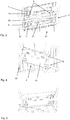
- the Fig. 1 shows the base body 2 in the not yet fully assembled state with a view of the inside of the half-shells 4 and 5.
- a half-shell 4 which is connected to a second half-shell 5 by means of two film hinges 6.
- One half-shell 5 has six spring elements 7 and 8. These store two wires (not shown) passed through the base body 2 under spring tension.
- a centering element 9 can be seen. This is designed as a spring element.
- a support element 10 serves as a spacer of the one half-shell 4 compared to the other half-shell 5 in the area of the half-shell center.
- the illustration shows connecting elements with an L-shaped projection 11, provided by the one half-shell 5, and connecting elements on the other shell side with a recess 12.
- the connecting elements 11 and 12 are formed in one piece with the half-shells 4 and 5. Both connecting elements 11 and 12 are designed to correspond to one another in the final assembled state. Furthermore, a half-shell 5 has wire receptacles 18 machined into the half-shell base surface 16, which together with the U-shaped recesses 17 form the receptacle for a wire. The other half-shell 4 has essentially U-shaped recesses 17, which correspond to the recesses 17 of the half-shell 5 in the final assembled state.
- Fig. 2 shows a handle panel 3 with a J-shaped configuration.
- the grip panel 3 has connecting elements 15 which provide an L-shaped projection.
- Four connecting elements 15 are arranged in the region of the semicircular curvature of the grip panel 3.
- two connecting elements 15 are arranged on the handle panel 3.
- Fig. 3 shows the open base body 2 resting against the wire basket 22.
- Two wires 20 are inserted into the U-shaped recesses 17 and are in contact with the spring elements 7 and 8 of the one half-shell 5.
- the upper wire 20 has a double S-shaped wire section which provides a bead 21.
- the centering element 9 of the half-shell 5 engages in the bead 21.
- the wires 20 are still in the wire guides (see Figure 1 ) the half shell 5 out.
- the open base body 2 can be assembled in a simple manner with a single handle.
- the connecting elements 11 and 12 snap into place and form in the final assembled state (cf. Fig. 4 ) a snap connection.
- Fig. 4 shows the final assembled base body 2 on the wire basket 22.
- the corresponding U-shaped recesses 17 of the two half-shells 4 and 5 form the wire receptacle 19 in the final assembled state.
- the outside half-shell surface 13 is also shown. Ribs and / or connecting elements can be seen. In order to provide an optically and haptically high-quality surface within the meaning of the object of the present invention, further measures are necessary.
- the outside shell surface 13 must be covered by suitable means.
- Fig. 5 shows the final assembled base body 2 on the wire basket 22.
- the grip panel 3 rests on the base body 2. It can be seen that the connecting elements 15 of the grip panel 3 lie in the curved region of the J-shape in the recesses provided in the base body 2. In the vertical part of the grip panel 3, the connection elements 15 provided are still to be mounted on the base body 2.
- Fig. 6 shows the final assembled state.
- the grip panel 3 is now locked to the base body 2 by simple compression.
- the connection between the grip panel 3 and the base body 2 is designed without play.
- Base body 2 and handle cover 3 together form the handle 1.
- the outside handle cover surface 14 is of high quality in terms of appearance and feel.
Landscapes
- Washing And Drying Of Tableware (AREA)
- Details Of Rigid Or Semi-Rigid Containers (AREA)
Description
- Die Erfindung betrifft einen Griff für einen Drahtkorb, insbesondere Unterkorb einer Spülmaschine, welcher durch einen Anwender in den Beschickungsraum einer Spülmaschine ein- und ausfahrbar ist.
- Drahtkörbe für Spülmaschinen sind im Allgemeinen derart ausgebildet, dass ein Benutzer sie manuell aus der Spülmaschine herausziehen und in die Spülmaschine hineinschieben kann. Der Benutzer fasst hierzu den Drahtkorb an einem der Drähte oder, im Falle hochwertigerer Spülmaschinen, an einem am Drahtkorb vorgesehenen Griff an.
- Aus dem Stand der Technik bekannte Griffe für Drahtkörbe haben den Nachteil, dass die Verbindung des Griffs mit dem Drahtkorb ein für den Benutzer wahrnehmbares Spiel aufweist. Darüber hinaus erreichen vorbekannte Griffe keine für den Benutzer ansprechende Optik und Haptik, da sie sicht- und fühlbare Unebenheiten aufweisen, welche beispielsweise durch Konturen verursacht sind. Weiterhin ist die Montage vorbekannter Griffe aufwendig, da diese Griffe aus mehreren Teilen bestehen und mit separaten Befestigungsmitteln befestigt werden.
- Aus der
US 2008/0272074 A1 ist ein Griff für einen Drahtkorb bekannt mit einem aus zwei Halbschalen bestehenden Grundkörper. Die Halbschalen weisen korrespondierend zueinander ausgebildete Drahtaufnahmen auf, mittels derer ein Draht des Drahtkorbes zwischen ihnen aufgenommen wird,
Es ist die Aufgabe der Erfindung, einen Griff für einen Drahtkorb, insbesondere Unterkorb einer Spülmaschine, vorzuschlagen, der bei gleichzeitig verbessertem Bedienkomfort auf einfache Weise montiert werden kann. - Zur Lösung dieser Aufgabe wird mit der Erfindung ein Griff mit einem aus zwei Halbschalen bestehenden Grundkörper vorgeschlagen, die im endmontierten Zustand einen Draht des Drahtkorbs spieifrei zwischen sich aufnehmen, zu weichem Zweck die Halbschalen korrespondierend zueinander ausgebildete Drahtaufnahmen bereitstellen, die federelastisch ausgebildet sind.
- Gemäß einem Merkmal der Erfindung weist der erfindungsgemäße Griff einen aus zwei Halbschalen bestehenden Grundkörper auf. Diese nehmen im endmontierten Zustand einen Draht des Drahtkorbs spielfrei zwischen sich auf. Dies wird erfindungsgemäß dadurch erreicht, dass die Halbschalen Drahtaufnahmen aufweisen, die den Draht in allen sechs Freiheitsgraden des Raumes lagern. Die Drahtaufnahmen sind federelastisch ausgebildet, so dass im endmontierten Zustand zwischen dem Grundkörper einerseits und dem Draht andererseits eine Federspannung herrscht. In vorteilhafter Weise ist ein derartig ausgebildeter Griff spielfrei am Drahtkorb angeordnet. Eine relative Bewegung des Griffs gegenüber dem Korb, was ein Benutzer als "Wackeln" wahrnehmen würde, ist in vorteilhafter Weise unterbunden. In vorteilhafter Weise wird eine Krafteinwirkung eines Benutzers auf den Griff unmittelbar auf den Drahtkorb übertragen, und führt nicht zu einem "Wackeln", "Kippen" und/oder Verdrehen des Griffs gegenüber dem Drahtkorb. In besonders vorteilhafter Weise nimmt ein Benutzer den Drahtkorb mit dem erfindungsgemäßen Griff als besonders hochwertiges Produkt wahr.
- Gemäß einem weiteren Merkmal der Erfindung stellen die Halbschalen korrespondierend zueinander ausgebildete Drahtaufnahmen bereit. Dabei sind die Drahtaufnahmen in ihrer geometrischen Ausgestaltung auf die Kontur, insbesondere Querschnittskontur des Drahtes abgestimmt ausgebildet. In einer bevorzugten Ausführungsform sind die Drahtaufnahmen teilkreisförmig ausgebildet und umschließen den aufgenommenen Draht im endmontierten Zustand. Die Halbschalen können dabei für einen Draht eine Drahtaufnahme oder auch Drahtaufnahmen für zwei oder mehr Drähte bereitstellen. Die erfindungsgemäße Ausbildung einer Drahtaufnahme, verteilt auf zwei Halbschalen, ermöglicht dabei in vorteilhafter Weise eine vereinfachte Montage des Griffs am Drahtkorb. Die eine Halbschale und die andere Halbschale werden unter Zwischenordnung eines oder mehrerer Drähte zusammengefügt und miteinander verbunden.
- Gemäß einem weiteren Merkmal der Erfindung sind die Drahtaufnahmen federelastisch ausgebildet. Dabei kann es vorgesehen sein, dass das Material des Grundkörpers selbst federelastisch ist, so dass der Draht mit den zwei Halbschalen eine Presspassung bildet, wobei das Material des Grundkörpers selbst als Feder dient und im endmontierten Zustand unter Federspannung steht. Insbesondere kann aber auch vorgesehen sein, dass die Halbschalen im Bereich der Drahtaufnahmen im Wesentlichen eine Spielpassung mit dem Draht bilden, und an den Halbschalen Federelemente vorgesehen sind, welche die Verbindung von Griff und Drahtkorb im endmontierten Zustand spielfrei ausgestalten. In vorteilhafter Weise ist somit die Wahl des Werkstoffs für die Halbschalen nicht eingeschränkt. Besonders vorteilhaft ist es, dass mögliche Fertigungstoleranzen durch die Federelemente ausgeglichen werden können. Somit sind auch kostengünstigere Fertigungsverfahren, beispielsweise das Spritzgussverfahren, zur Herstellung des erfindungsgemäßen Griffs möglich, bei gleichzeitig als erhöht wahrgenommener Qualität durch einen Benutzer.
- Gemäß einem weiteren Merkmal der Erfindung weist eine der Drahtaufnahmen des erfindungsgemäßen Griffs eine Mittenzentrierung auf, die im endmontierten Zustand in eine vom Draht bereitgestellte Sicke eingreift. Am Drahtkorb ist dazu ein Draht vorgesehen, der eine Sicke bereitstellt, in welche im endmontierten Zustand ein Gegenlager eingreift, beispielsweise in Form eines am Griff angeordneten U- oder V-förmigen Elements, das insbesondere auch als Federelement ausgebildet sein kann. Die zu diesem Element korrespondierende Drahtsicke kann durch eine U-förmige oder zwei S-förmige Abbiegungen des Drahts gebildet sein. In vorteilhafter Weise ist durch die Mittenzentrierung die Position des Griffs am Drahtkorb festgelegt. Insbesondere im Hinblick auf eine Montage ist es vorteilhaft, dass der Griff nicht am Drahtkorb ausgerichtet werden muss, sondern seine Position bereits konstruktiv festgelegt ist. Die Mittenzentrierung hat einen weiteren Vorteil. Das Element zur Mittenzentrierung bildet mit der dazu korrespondierenden Drahtsicke eine formschlüssige Verbindung aus. Somit ist ein Verrutschen des Griffs in Richtung der Längserstreckung des Drahtes, d. h. eine Relativverschiebung nicht möglich. Besonders vorteilhaft ist hierbei die Ausgestaltung der Mittenzentrierung als Federelement. Der Grundkörper ist hierbei im endmontierten Zustand unter Federspannung in der als Federelement ausgelegten Mittenzentrierung gegenüber dem Drahtkorb spielfrei gelagert.
- Gemäß einem weiteren Merkmal der Erfindung weisen die Halbschalen des erfindungsgemäßen Griffs korrespondierend zueinander ausgebildete Verbindungselemente auf. Derartige Verbindungselemente halten die beiden Halbschalen, denen zumindest ein Draht des Drahtkorbs zwischengeordnet ist, im endmontierten Zustand verbunden. Derartige Verbindungselemente können beispielsweise im endmontierten Zustand eine form-, eine kraft- und/oder eine stoffschlüssige Verbindung der beiden Halbschalen bereitstellen. In vorteilhafter Weise lässt sich bei einer Montage der Griff mit einem Handgriff an einem oder mehreren Drähten anfügen und mit den Verbindungselementen fixieren.
- Gemäß einer bevorzugten Ausführungsform der Erfindung bilden die zueinander korrespondierend ausgebildeten Verbindungselemente der beiden Halbschalen eine formschlüssige Verbindung. Die Verbindungselemente können hierbei durch Schrauben, Bolzen, Nieten, Druckknöpfe, Rastverbindungen oder dergleichen gebildet werden. In vorteilhafter Weise stellen derartige Verbindungselemente eine formschlüssige und mechanisch einfach zu realisierende Verbindung bereit.
- Gemäß einer besonders bevorzugten Ausführungsform der Erfindung bilden die zueinander korrespondierend ausgebildeten Verbindungselemente der beiden Halbschalen eine Rastverbindung. Hierzu weisen die Verbindungselemente einschalenseitig einen L-förmigen Vorsprung und andersschalenseitig eine Ausnehmung auf, wobei der L-förmige Vorsprung mit der Ausnehmung im endmontierten Zustand eine Rastverbindung bildet. Vorteilhaft ist insbesondere, dass sich derartige Verbindungselemente ohne ein Werkzeug verbinden lassen, und vielmehr durch einfaches Zusammendrücken beider Halbschalen einrasten, womit eine vereinfachte Montage erreicht ist.
- Gemäß einem weiteren Merkmal der Erfindung weisen die Halbschalen Ausnehmungen auf, die derart ausgebildet sind, dass die beschriebene Rastverbindung durch die Ausnehmungen mit einem geeigneten Werkzeug durch Biegen, Drücken oder dergleichen gelöst werden kann. In vorteilhafter Weise kann der Griff somit, sofern es erforderlich sein sollte, zerstörungsfrei vom Drahtkorb getrennt werden.
- Gemäß einem weiteren Merkmal der Erfindung sind die Halbschalen des Griffs mittels eines Filmscharniers relativ zueinander verschwenkbar ausgebildet. Dabei können die beiden Halbschalen durch ein Filmscharnier, vorzugsweise aber durch zwei oder drei Filmscharniere miteinander verbunden sein. Ein derartiges Filmscharnier ist vorzugsweise einstückig mit den beiden Halbschalen ausgebildet. In einem geeigneten Fertigungsverfahren, beispielsweise dem Spritzgussverfahren, können die Halbschalen und das Filmscharnier aus dem gleichen Werkstoff gebildet werden. Weiterhin kann somit der gesamte Grundkörper aus einem Stück gefertigt werden. Das Filmscharnier ist derart ausgebildet, dass sich die beiden Halbschalen relativ zueinander verschwenken lassen, insbesondere derart, dass sie in einer bestimmten Schwenkposition korrespondierend zueinander aneinander anliegen. Insbesondere ist es erfindungsgemäß in dieser Position auch vorgesehen, dass die beschriebenen Verbindungselemente korrespondierend zueinander liegen. Besonders bevorzugt bilden die beschriebenen Verbindungselemente mit L-förmigem Vorsprung und dazu korrespondierender Ausnehmung in der beschriebenen Schwenkposition die beschriebene vorteilhafte Rastverbindung. In vorteilhafter Weise lässt sich somit der Grundkörper mit der einen Halbschale am Draht eines Drahtkorbs anlegen, und durch Verschwenken der anderen Halbschale um eine Achse des Filmscharniers unter Zwischenordnung des zumindest einen Drahts schließen, wobei das einen L-förmigen Vorsprung aufweisende Verbindungselement mit dem andersschalenseitigen, eine Ausnehmung aufweisenden Verbindungselement eine Rastverbindung eingeht. Der gesamte Grundkörper ist hierbei einstückig ausgebildet, so dass die Montage des Grundkörpers am Drahtkorb dem Grunde nach durch einen einzigen Handgriff durchzuführen ist. In besonders vorteilhafter Weise liegt also eine vereinfachte Handhabung gegenüber dem Stand der Technik vor.
- Gemäß einem weiteren Merkmal der Erfindung besteht der Grundkörper des Griffs aus Kunststoff, vorzugsweise einem solchen Kunststoff, der den in einer Spülmaschine auftretenden Belastungen standhält, und somit verschleißarm ist. Der Vorteil eines Kunststoffmaterials ist der mögliche Einsatz kostengünstiger Produktionsverfahren, beispielsweise dem Spritzgussverfahren oder dergleichen.
- Gemäß einem weiteren Merkmal der Erfindung weist der Griff eine Griffblende auf. Die Griffblende schmiegt sich in vorteilhafter Weise im endmontierten Zustand im Wesentlichen vollständig an den Grundkörper an. Die Griffblende kann dabei die Mantelfläche des Grundkörpers vollständig oder nur teilweise bedecken. Entscheidend ist, dass die Griffblende eine im Vergleich zur Mantelfläche des Grundkörpers hochwertige Optik und Haptik bereitstellt. In vorteilhafter Weise führt die Verwendung einer erfindungsgemäßen Griffblende dazu, dass ein einstückig ausgebildeter, kostengünstig hergestellter Grundkörper mit einer hochwertigen Oberfläche ausgestattet werden kann.
- Eine erfindungsgemäße Griffblende kann eine im Wesentlichen flache Form haben, kann jedoch auch jede weitere beliebige Form annehmen. Insbesondere ist eine J- oder U-Form zu wählen, welche zur Außenkontur des Grundkörpers korrespondierend ausgebildet ist. Die Griffblende schmiegt sich somit im endmontierten Zustand im Wesentlichen vollständig an den Grundkörper an. Die Griffblende kann aus jedem beliebigen Material gefertigt sein, insbesondere kann dies ein Kunststoff, Metall, Gummi oder dergleichen sein. Besonders vorteilhaft ist hierbei, dass die Wahl des Materials der Griffblende unabhängig von dem gewählten Material des Grundkörpers erfolgen kann.
- Insbesondere ist vorgesehen, dass die Griffblende eine glatte äußere Mantelfläche aufweist. Insbesondere weist die äußere Mantelfläche der Griffblende keine Kanten auf. In vorteilhafter Weise ergibt sich damit für den Benutzer ein hochwertiger optischer und/oder haptischer Eindruck. Ein weiterer Vorteil dieser Ausgestaltung ist, dass sich mögliche Keime oder beispielsweise Essensreste nicht am Griff festsetzen können. Der Einsatz der erfindungsgemäßen Griffblende sowie die Ausgestaltung mit einer glatten äußeren Mantelfläche ist also auch unter hygienischen Gesichtspunkten vorteilhaft.
- Gemäß einem weiteren Merkmal der Erfindung ist es vorgesehen, dass die Griffblende Verbindungselemente aufweist, welche einen L-förmigen Vorsprung aufweisen und im endmontierten Zustand mit dem Grundkörper eine Rastverbindung bilden. Dazu sind am Grundkörper Ausnehmungen vorgesehen, die an zu den L-förmigen Verbindungselementen der Griffblende korrespondierenden Stellen ausgebildet sind. Bevorzugterweise ist die Griffblende J-förmig ausgebildet, so dass sie den Grundkörper in einem Bereich von 180° umschließt.
- Gemäß einem weiteren Merkmal der Erfindung ist die Griffblende spielfrei mit dem Grundkörper verbunden. Dazu kann der Grundkörper in Richtung der Griffblende wirkende Federelemente aufweisen und/oder die Griffblende kann in Richtung des Grundkörpers wirkende Federelemente aufweisen. Diese Federelemente stehen im endmontierten Zustand zwischen Griffblende und Grundkörper unter Federspannung. Die Griffblende ist damit spielfrei am Grundkörper montiert. In vorteilhafter Weise ergibt sich für einen Benutzer ein hochwertiger Eindruck des an den Drahtkorb hinzugefügten Griffs. Weiterhin besonders vorteilhaft ist es, dass die Griffblende einen L-förmigen Vorsprung aufweisende Verbindungselemente bereitstellt, wodurch die Griffblende am Grundkörper durch einfaches Verrasten montiert werden kann.
- Weitere Vorteile und Merkmale der Erfindung ergeben sich aus der nachfolgenden Beschreibung anhand der Figuren. Dabei zeigen:
- Fig. 1
- Grundkörper des Griffs in geöffneter Stellung,
- Fig. 2
- Griffblende in perspektivischer Darstellung,
- Fig. 3
- geöffneter Grundkörper einschalenseitig an den Drahtkorb gefügt,
- Fig. 4
- endmontierter Grundkörper am Drahtkorb in perspektivischer Darstellung,
- Fig. 5
- endmontierter Grundkörper mit angefügter Griffblende vor der Montage,
- Fig. 6
- endmontierter Griff mit Grundkörper und Griffblende.
- Die
Fig. 1 zeigt den Grundkörper 2 im noch nicht endmontierten Zustand mit Sicht auf die Innenseiten der Halbschalen 4 und 5. Zu sehen ist eine Halbschale 4, welche mittels zwei Filmscharnieren 6 mit einer zweiten Halbschale 5 verbunden ist. Die eine Halbschale 5 weist sechs Federelemente 7 und 8 auf. Diese lagern zwei durch den Grundkörper 2 geführte Drähte (nicht dargestellt) unter Federspannung. Des Weiteren ist ein Zentrierelement 9 zu sehen. Dieses ist als Federelement ausgebildet. Ein Auflagerelement 10 dient als Abstandshalter der einen Halbschale 4 gegenüber der anderen Halbschale 5 im Bereich der Halbschalenmitte. Ferner zeigt die Abbildung Verbindungselemente mit einem L-förmigen Vorsprung 11, bereitgestellt durch die eine Halbschale 5, und andersschalenseitige Verbindungselemente mit einer Ausnehmung 12. Die Verbindungselemente 11 und 12 sind mit den Halbschalen 4 und 5 einstückig ausgebildet. Beide Verbindungselemente 11 und 12 sind im endmontierten Zustand korrespondierend zueinander ausgebildet. Ferner weist eine Halbschale 5 in die Halbschalengrundfläche 16 eingearbeitete Drahtaufnahmen 18 auf, welche zusammen mit den U-förmigen Ausnehmungen 17 die Aufnahme für einen Draht bilden. Die andere Halbschale 4 weist im Wesentlichen U-förmige Ausnehmungen 17 auf, welche im endmontierten Zustand zu den Ausnehmungen 17 der Halbschale 5 korrespondieren. -
Fig. 2 zeigt eine Griffblende 3 mit einer J-förmigen Ausgestaltung. Die Griffblende 3 weist Verbindungselemente 15 auf, welche einen L-förmigen Vorsprung bereitstellen. Im Bereich der halbkreisförmigen Krümmung der Griffblende 3 sind vier Verbindungselemente 15 angeordnet. Anderendseitig sind zwei Verbindungselemente 15 an der Griffblende 3 angeordnet. -
Fig. 3 zeigt den am Drahtkorb 22 anliegenden offenen Grundkörper 2. Zwei Drähte 20 sind in die U-förmigen Ausnehmungen 17 gefügt, und stehen mit den Federelementen 7 und 8 der einen Halbschale 5 im Kontakt. Der obere Draht 20 weist einen doppelt S-förmig ausgebildeten Drahtabschnitt auf, welcher eine Sicke 21 bereitstellt. Das Zentrierelement 9 der Halbschale 5 greift in die Sicke 21 ein. Die Drähte 20 sind weiterhin in den Drahtführungen (vergleicheFigur 1 ) der Halbschale 5 geführt. In einfacher Weise ist der geöffnete Grundkörper 2 durch einen einzigen Handgriff zu montieren. Dabei rasten die Verbindungselemente 11 und 12 ein und bilden im endmontierten Zustand (vergleicheFig. 4 ) eine Rastverbindung. -
Fig. 4 zeigt den endmontierten Grundkörper 2 am Drahtkorb 22. Die zueinander korrespondierenden U-förmigen Ausnehmungen 17 beider Halbschalen 4 und 5 bilden im endmontierten Zustand die Drahtaufnahme 19. Dargestellt ist weiterhin die außenseitige Halbschalenoberfläche 13. Zu sehen ist, dass aus fertigungstechnischen Gründen ausgebildete innenliegende Konturen, Rippen und/oder Verbindungselemente zu sehen sind. Um eine optisch und haptisch hochwertige Oberfläche im Sinne der Aufgabe der vorliegenden Erfindung bereitzustellen sind weitere Maßnahmen erforderlich. Die außenseitige Schalenoberfläche 13 muss durch geeignete Mittel abgedeckt werden. -
Fig. 5 zeigt den endmontierten Grundkörper 2 am Drahtkorb 22. Am Grundkörper 2 liegt die Griffblende 3 an. Zu sehen ist, dass die Verbindungselemente 15 der Griffblende 3 im gekrümmten Bereich der J-Form in den dazu vorgesehenen Ausnehmungen des Grundkörpers 2 anliegen. Im senkrechten Teil der Griffblende 3 sind die bereitgestellten Verbindungselemente 15 noch am Grundkörper 2 zu montieren. -
Fig. 6 zeigt den endmontierten Zustand. Die Griffblende 3 ist nun durch einfaches Zusammendrücken mit dem Grundkörper 2 verrastet. Die Verbindung zwischen Griffblende 3 und Grundkörper 2 ist spielfrei ausgebildet. Grundkörper 2 und Griffblende 3 bilden zusammen den Griff 1. Die außenseitige Griffblendenoberfläche 14 ist optisch und haptisch hochwertig ausgebildet.
Claims (10)
- Griff (1) für einen Drahtkorb (22), insbesondere Unterkorb einer Spülmaschine, mit einem aus zwei Halbschalen (4, 5) bestehenden Grundkörper (2), die im endmontierten Zustand einen Draht (20) des Drahtkorbs (22) zwischen sich aufnehmen, zu welchem Zweck die Halbschalen (4, 5) korrespondierend zueinander ausgebildete Drahtaufnahmen (18) bereitstellen,
dadurch gekennzeichnet,
dass die Drahtaufnahmen (18) federelastisch ausgebildet sind, derart dass im endmontierten Zustand zwischen dem Grundkörper (2) einerseits und dem Draht (20) andererseits eine Federspannung herrscht und der Griff (1) spielfrei am Drahtkorb (22) angeordnet ist. - Griff (1) nach Anspruch 1,
dadurch gekennzeichnet,
dass eine der Drahtaufnahmen (19) eine Mittenzentrierung (9) aufweist, die im endmontierten Zustand in eine vom Draht (20) bereitgestellte Sicke (21) eingreift. - Griff (1) nach Anspruch 1 oder 2,
dadurch gekennzeichnet,
dass die Halbschalen (4, 5) korrespondierend zueinander ausgebildete Verbindungselemente (11, 12) aufweisen. - Griff (1) nach Anspruch 3,
dadurch gekennzeichnet,
dass die Verbindungselemente (11, 12) einschalenseitig einen L-förmigen Vorsprung und andersschalenseitig eine Ausnehmung aufweisen, wobei der L-förmige Vorsprung mit der Ausnehmung im endmontierten Zustand eine Rastverbindung bildet. - Griff (1) nach einem der vorangehenden Ansprüche,
dadurch gekennzeichnet,
dass die Halbschalen (4, 5) mittels eines Filmscharniers (6) relativ zueinander verschwenkbar ausgebildet sind. - Griff (1) nach einem der vorangehenden Ansprüche,
dadurch gekennzeichnet,
dass der Grundkörper (2) einstückig ausgebildet ist. - Griff (1) nach einem der vorangehenden Ansprüche,
dadurch gekennzeichnet,
dass der Grundkörper (2) aus Kunststoff gebildet ist. - Griff (1) nach einem der vorangehenden Ansprüche,
gekennzeichnet durch
eine Griffblende (3). - Griff (1) nach Anspruch 8,
dadurch gekennzeichnet,
dass die Griffblende (3) J-förmig ausgebildet ist. - Griff (1) nach Anspruch 8 oder 9,
dadurch gekennzeichnet,
dass die Griffblende (3) Verbindungselemente (15) mit einem L-förmigen Vorsprung aufweist, und mit dem Grundkörper (2) im endmontierten Zustand eine Rastverbindung bildet.
Priority Applications (1)
| Application Number | Priority Date | Filing Date | Title |
|---|---|---|---|
| EP10401053.3A EP2377454B1 (de) | 2010-04-13 | 2010-04-13 | Griff für einen Drahtkorb |
Applications Claiming Priority (1)
| Application Number | Priority Date | Filing Date | Title |
|---|---|---|---|
| EP10401053.3A EP2377454B1 (de) | 2010-04-13 | 2010-04-13 | Griff für einen Drahtkorb |
Publications (3)
| Publication Number | Publication Date |
|---|---|
| EP2377454A1 EP2377454A1 (de) | 2011-10-19 |
| EP2377454A8 EP2377454A8 (de) | 2012-01-11 |
| EP2377454B1 true EP2377454B1 (de) | 2019-12-25 |
Family
ID=42712395
Family Applications (1)
| Application Number | Title | Priority Date | Filing Date |
|---|---|---|---|
| EP10401053.3A Active EP2377454B1 (de) | 2010-04-13 | 2010-04-13 | Griff für einen Drahtkorb |
Country Status (1)
| Country | Link |
|---|---|
| EP (1) | EP2377454B1 (de) |
Families Citing this family (5)
| Publication number | Priority date | Publication date | Assignee | Title |
|---|---|---|---|---|
| DE102013211531A1 (de) * | 2013-06-19 | 2014-12-24 | BSH Bosch und Siemens Hausgeräte GmbH | Anordnung für eine Geschirrspülmaschine |
| US9629516B2 (en) * | 2014-10-08 | 2017-04-25 | Whirlpool Corporation | Dishwasher rack handle |
| DE102018133024A1 (de) * | 2018-12-20 | 2020-06-25 | Miele & Cie. Kg | Leistensystem |
| DE102023100972A1 (de) * | 2023-01-17 | 2024-07-18 | Elma Schmidbauer Gmbh | Modular Reinigungskorb und Reinigungskorbsystem |
| BE1031657B1 (de) * | 2023-05-31 | 2025-01-13 | Miele & Cie | Spülkorb für eine Geschirrspülmaschine |
Family Cites Families (4)
| Publication number | Priority date | Publication date | Assignee | Title |
|---|---|---|---|---|
| IT243408Y1 (it) * | 1997-01-23 | 2002-03-04 | Electrolux Zanussi Elettrodome | Cesto estraibile per lavastoviglie |
| DE10259087B4 (de) * | 2002-12-17 | 2004-11-25 | BSH Bosch und Siemens Hausgeräte GmbH | Geschirrkorb für eine Geschirrspülmaschine sowie Griff für einen Geschirrkorb |
| US8303725B2 (en) | 2007-05-04 | 2012-11-06 | Electrolux Home Products, Inc. | Rack handle member for a dishwasher |
| KR20090001791U (ko) * | 2007-08-21 | 2009-02-25 | 삼성전자주식회사 | 식기세척기 |
-
2010
- 2010-04-13 EP EP10401053.3A patent/EP2377454B1/de active Active
Non-Patent Citations (1)
| Title |
|---|
| None * |
Also Published As
| Publication number | Publication date |
|---|---|
| EP2377454A1 (de) | 2011-10-19 |
| EP2377454A8 (de) | 2012-01-11 |
Similar Documents
| Publication | Publication Date | Title |
|---|---|---|
| EP2477844B1 (de) | Einteilige kunststoff-klemmeinrichtung für einen halter für getränkebehälter | |
| DE102010037805B4 (de) | Türverkleidung mit einer Handgriffvorrichtung | |
| WO2016177706A1 (de) | Möbelscharnier mit einem dämpfer und einer feder | |
| EP2377454A1 (de) | Griff für einen Drahtkorb | |
| EP3078794B1 (de) | Schwenkvorrichtung für ein kraftfahrzeug mit einfach zu montierender und zugleich sicherer schwenklagerung | |
| EP3094212A1 (de) | Schwenkgelenk und möbelstück mit einem solchen | |
| DE10043720B4 (de) | Halter für Gefäße | |
| EP1470624B1 (de) | Geräteeinschub für eine schaltanlage mit hilfstrennkontakten | |
| EP1716012B1 (de) | Komponente, insbesondere sonnenblende und insbesondere für ein fahrzeug, verfahren zur herstellung einer komponente | |
| DE102011004415A1 (de) | Schaltwelle mit einer offenen Hülse | |
| EP2467657B1 (de) | Tür für ein haushaltsgerät mit griffeinsatz | |
| DE102012110696A1 (de) | Türinnengriff zum Drücken | |
| DE102016216101A1 (de) | Verbindungsvorrichtung zum Ankuppeln einer Aufsatzeinrichtung an eine Küchenmaschine | |
| DE102015011828A1 (de) | Befestigungsvorrlchtung, Gassackmodul oder Lenkrad mlt elner solchen Befestigungsvorrlchtung und Montageverfahren | |
| DE10256842B4 (de) | Griff mit einem sicht- und umfassbaren Griffteil und mehreren Funktionsteilen | |
| EP3801133B1 (de) | Zarge für einen schubkasten | |
| EP2617325B1 (de) | Rückenlehne für ein Sitzmöbel | |
| DE10306733B4 (de) | Vorrichtung zur Arretierung, Körper und Anordnung | |
| DE202012009798U1 (de) | Hub-Schwenkbeschlag | |
| DE102007029130B4 (de) | Halter für Gebrauchs-Gegenstände | |
| EP1315636B1 (de) | Kunststoffummantelte verzurröse mit verstärkungseinlage | |
| DE102020212459A1 (de) | Verstelleinrichtung für eine Fahrzeugsitzbaugruppe | |
| EP3992350B1 (de) | Griffbaugruppe für eine waschmaschine | |
| DE102004038143A1 (de) | Abfallsammler | |
| DE102011106146B4 (de) | Sonnenblende für ein Kraftfahrzeug |
Legal Events
| Date | Code | Title | Description |
|---|---|---|---|
| AK | Designated contracting states |
Kind code of ref document: A1 Designated state(s): AT BE BG CH CY CZ DE DK EE ES FI FR GB GR HR HU IE IS IT LI LT LU LV MC MK MT NL NO PL PT RO SE SI SK SM TR |
|
| AX | Request for extension of the european patent |
Extension state: AL BA ME RS |
|
| PUAI | Public reference made under article 153(3) epc to a published international application that has entered the european phase |
Free format text: ORIGINAL CODE: 0009012 |
|
| 17P | Request for examination filed |
Effective date: 20120327 |
|
| GRAP | Despatch of communication of intention to grant a patent |
Free format text: ORIGINAL CODE: EPIDOSNIGR1 |
|
| STAA | Information on the status of an ep patent application or granted ep patent |
Free format text: STATUS: GRANT OF PATENT IS INTENDED |
|
| INTG | Intention to grant announced |
Effective date: 20190828 |
|
| GRAS | Grant fee paid |
Free format text: ORIGINAL CODE: EPIDOSNIGR3 |
|
| GRAA | (expected) grant |
Free format text: ORIGINAL CODE: 0009210 |
|
| STAA | Information on the status of an ep patent application or granted ep patent |
Free format text: STATUS: THE PATENT HAS BEEN GRANTED |
|
| REG | Reference to a national code |
Ref country code: DE Ref legal event code: R084 Ref document number: 502010016428 Country of ref document: DE |
|
| AK | Designated contracting states |
Kind code of ref document: B1 Designated state(s): AT BE BG CH CY CZ DE DK EE ES FI FR GB GR HR HU IE IS IT LI LT LU LV MC MK MT NL NO PL PT RO SE SI SK SM TR |
|
| REG | Reference to a national code |
Ref country code: GB Ref legal event code: FG4D Free format text: NOT ENGLISH |
|
| REG | Reference to a national code |
Ref country code: CH Ref legal event code: EP |
|
| REG | Reference to a national code |
Ref country code: AT Ref legal event code: REF Ref document number: 1216195 Country of ref document: AT Kind code of ref document: T Effective date: 20200115 |
|
| REG | Reference to a national code |
Ref country code: DE Ref legal event code: R096 Ref document number: 502010016428 Country of ref document: DE |
|
| REG | Reference to a national code |
Ref country code: IE Ref legal event code: FG4D Free format text: LANGUAGE OF EP DOCUMENT: GERMAN |
|
| REG | Reference to a national code |
Ref country code: GB Ref legal event code: 746 Effective date: 20200205 |
|
| REG | Reference to a national code |
Ref country code: NL Ref legal event code: MP Effective date: 20191225 |
|
| PG25 | Lapsed in a contracting state [announced via postgrant information from national office to epo] |
Ref country code: BG Free format text: LAPSE BECAUSE OF FAILURE TO SUBMIT A TRANSLATION OF THE DESCRIPTION OR TO PAY THE FEE WITHIN THE PRESCRIBED TIME-LIMIT Effective date: 20200325 Ref country code: FI Free format text: LAPSE BECAUSE OF FAILURE TO SUBMIT A TRANSLATION OF THE DESCRIPTION OR TO PAY THE FEE WITHIN THE PRESCRIBED TIME-LIMIT Effective date: 20191225 Ref country code: LV Free format text: LAPSE BECAUSE OF FAILURE TO SUBMIT A TRANSLATION OF THE DESCRIPTION OR TO PAY THE FEE WITHIN THE PRESCRIBED TIME-LIMIT Effective date: 20191225 Ref country code: SE Free format text: LAPSE BECAUSE OF FAILURE TO SUBMIT A TRANSLATION OF THE DESCRIPTION OR TO PAY THE FEE WITHIN THE PRESCRIBED TIME-LIMIT Effective date: 20191225 Ref country code: NO Free format text: LAPSE BECAUSE OF FAILURE TO SUBMIT A TRANSLATION OF THE DESCRIPTION OR TO PAY THE FEE WITHIN THE PRESCRIBED TIME-LIMIT Effective date: 20200325 Ref country code: GR Free format text: LAPSE BECAUSE OF FAILURE TO SUBMIT A TRANSLATION OF THE DESCRIPTION OR TO PAY THE FEE WITHIN THE PRESCRIBED TIME-LIMIT Effective date: 20200326 Ref country code: LT Free format text: LAPSE BECAUSE OF FAILURE TO SUBMIT A TRANSLATION OF THE DESCRIPTION OR TO PAY THE FEE WITHIN THE PRESCRIBED TIME-LIMIT Effective date: 20191225 |
|
| REG | Reference to a national code |
Ref country code: LT Ref legal event code: MG4D |
|
| PG25 | Lapsed in a contracting state [announced via postgrant information from national office to epo] |
Ref country code: HR Free format text: LAPSE BECAUSE OF FAILURE TO SUBMIT A TRANSLATION OF THE DESCRIPTION OR TO PAY THE FEE WITHIN THE PRESCRIBED TIME-LIMIT Effective date: 20191225 |
|
| PG25 | Lapsed in a contracting state [announced via postgrant information from national office to epo] |
Ref country code: RO Free format text: LAPSE BECAUSE OF FAILURE TO SUBMIT A TRANSLATION OF THE DESCRIPTION OR TO PAY THE FEE WITHIN THE PRESCRIBED TIME-LIMIT Effective date: 20191225 Ref country code: PT Free format text: LAPSE BECAUSE OF FAILURE TO SUBMIT A TRANSLATION OF THE DESCRIPTION OR TO PAY THE FEE WITHIN THE PRESCRIBED TIME-LIMIT Effective date: 20200520 Ref country code: NL Free format text: LAPSE BECAUSE OF FAILURE TO SUBMIT A TRANSLATION OF THE DESCRIPTION OR TO PAY THE FEE WITHIN THE PRESCRIBED TIME-LIMIT Effective date: 20191225 Ref country code: CZ Free format text: LAPSE BECAUSE OF FAILURE TO SUBMIT A TRANSLATION OF THE DESCRIPTION OR TO PAY THE FEE WITHIN THE PRESCRIBED TIME-LIMIT Effective date: 20191225 Ref country code: EE Free format text: LAPSE BECAUSE OF FAILURE TO SUBMIT A TRANSLATION OF THE DESCRIPTION OR TO PAY THE FEE WITHIN THE PRESCRIBED TIME-LIMIT Effective date: 20191225 |
|
| PG25 | Lapsed in a contracting state [announced via postgrant information from national office to epo] |
Ref country code: SK Free format text: LAPSE BECAUSE OF FAILURE TO SUBMIT A TRANSLATION OF THE DESCRIPTION OR TO PAY THE FEE WITHIN THE PRESCRIBED TIME-LIMIT Effective date: 20191225 Ref country code: IS Free format text: LAPSE BECAUSE OF FAILURE TO SUBMIT A TRANSLATION OF THE DESCRIPTION OR TO PAY THE FEE WITHIN THE PRESCRIBED TIME-LIMIT Effective date: 20200425 Ref country code: SM Free format text: LAPSE BECAUSE OF FAILURE TO SUBMIT A TRANSLATION OF THE DESCRIPTION OR TO PAY THE FEE WITHIN THE PRESCRIBED TIME-LIMIT Effective date: 20191225 |
|
| REG | Reference to a national code |
Ref country code: DE Ref legal event code: R097 Ref document number: 502010016428 Country of ref document: DE |
|
| PG25 | Lapsed in a contracting state [announced via postgrant information from national office to epo] |
Ref country code: DK Free format text: LAPSE BECAUSE OF FAILURE TO SUBMIT A TRANSLATION OF THE DESCRIPTION OR TO PAY THE FEE WITHIN THE PRESCRIBED TIME-LIMIT Effective date: 20191225 Ref country code: ES Free format text: LAPSE BECAUSE OF FAILURE TO SUBMIT A TRANSLATION OF THE DESCRIPTION OR TO PAY THE FEE WITHIN THE PRESCRIBED TIME-LIMIT Effective date: 20191225 |
|
| PLBE | No opposition filed within time limit |
Free format text: ORIGINAL CODE: 0009261 |
|
| STAA | Information on the status of an ep patent application or granted ep patent |
Free format text: STATUS: NO OPPOSITION FILED WITHIN TIME LIMIT |
|
| PG25 | Lapsed in a contracting state [announced via postgrant information from national office to epo] |
Ref country code: MC Free format text: LAPSE BECAUSE OF FAILURE TO SUBMIT A TRANSLATION OF THE DESCRIPTION OR TO PAY THE FEE WITHIN THE PRESCRIBED TIME-LIMIT Effective date: 20191225 Ref country code: SI Free format text: LAPSE BECAUSE OF FAILURE TO SUBMIT A TRANSLATION OF THE DESCRIPTION OR TO PAY THE FEE WITHIN THE PRESCRIBED TIME-LIMIT Effective date: 20191225 |
|
| REG | Reference to a national code |
Ref country code: CH Ref legal event code: PL |
|
| 26N | No opposition filed |
Effective date: 20200928 |
|
| PG25 | Lapsed in a contracting state [announced via postgrant information from national office to epo] |
Ref country code: CH Free format text: LAPSE BECAUSE OF NON-PAYMENT OF DUE FEES Effective date: 20200430 Ref country code: LU Free format text: LAPSE BECAUSE OF NON-PAYMENT OF DUE FEES Effective date: 20200413 Ref country code: LI Free format text: LAPSE BECAUSE OF NON-PAYMENT OF DUE FEES Effective date: 20200430 |
|
| REG | Reference to a national code |
Ref country code: BE Ref legal event code: MM Effective date: 20200430 |
|
| PG25 | Lapsed in a contracting state [announced via postgrant information from national office to epo] |
Ref country code: PL Free format text: LAPSE BECAUSE OF FAILURE TO SUBMIT A TRANSLATION OF THE DESCRIPTION OR TO PAY THE FEE WITHIN THE PRESCRIBED TIME-LIMIT Effective date: 20191225 Ref country code: BE Free format text: LAPSE BECAUSE OF NON-PAYMENT OF DUE FEES Effective date: 20200430 |
|
| PG25 | Lapsed in a contracting state [announced via postgrant information from national office to epo] |
Ref country code: IE Free format text: LAPSE BECAUSE OF NON-PAYMENT OF DUE FEES Effective date: 20200413 |
|
| REG | Reference to a national code |
Ref country code: AT Ref legal event code: MM01 Ref document number: 1216195 Country of ref document: AT Kind code of ref document: T Effective date: 20200413 |
|
| PG25 | Lapsed in a contracting state [announced via postgrant information from national office to epo] |
Ref country code: AT Free format text: LAPSE BECAUSE OF NON-PAYMENT OF DUE FEES Effective date: 20200413 |
|
| PG25 | Lapsed in a contracting state [announced via postgrant information from national office to epo] |
Ref country code: MT Free format text: LAPSE BECAUSE OF FAILURE TO SUBMIT A TRANSLATION OF THE DESCRIPTION OR TO PAY THE FEE WITHIN THE PRESCRIBED TIME-LIMIT Effective date: 20191225 Ref country code: CY Free format text: LAPSE BECAUSE OF FAILURE TO SUBMIT A TRANSLATION OF THE DESCRIPTION OR TO PAY THE FEE WITHIN THE PRESCRIBED TIME-LIMIT Effective date: 20191225 |
|
| PG25 | Lapsed in a contracting state [announced via postgrant information from national office to epo] |
Ref country code: MK Free format text: LAPSE BECAUSE OF FAILURE TO SUBMIT A TRANSLATION OF THE DESCRIPTION OR TO PAY THE FEE WITHIN THE PRESCRIBED TIME-LIMIT Effective date: 20191225 |
|
| PGFP | Annual fee paid to national office [announced via postgrant information from national office to epo] |
Ref country code: TR Payment date: 20230330 Year of fee payment: 14 |
|
| P01 | Opt-out of the competence of the unified patent court (upc) registered |
Effective date: 20230529 |
|
| PGFP | Annual fee paid to national office [announced via postgrant information from national office to epo] |
Ref country code: IT Payment date: 20230421 Year of fee payment: 14 Ref country code: FR Payment date: 20230421 Year of fee payment: 14 |
|
| PGFP | Annual fee paid to national office [announced via postgrant information from national office to epo] |
Ref country code: GB Payment date: 20230418 Year of fee payment: 14 |
|
| GBPC | Gb: european patent ceased through non-payment of renewal fee |
Effective date: 20240413 |
|
| PG25 | Lapsed in a contracting state [announced via postgrant information from national office to epo] |
Ref country code: GB Free format text: LAPSE BECAUSE OF NON-PAYMENT OF DUE FEES Effective date: 20240413 |
|
| PG25 | Lapsed in a contracting state [announced via postgrant information from national office to epo] |
Ref country code: FR Free format text: LAPSE BECAUSE OF NON-PAYMENT OF DUE FEES Effective date: 20240430 |
|
| PG25 | Lapsed in a contracting state [announced via postgrant information from national office to epo] |
Ref country code: GB Free format text: LAPSE BECAUSE OF NON-PAYMENT OF DUE FEES Effective date: 20240413 Ref country code: FR Free format text: LAPSE BECAUSE OF NON-PAYMENT OF DUE FEES Effective date: 20240430 |
|
| PG25 | Lapsed in a contracting state [announced via postgrant information from national office to epo] |
Ref country code: IT Free format text: LAPSE BECAUSE OF NON-PAYMENT OF DUE FEES Effective date: 20240413 |
|
| PGFP | Annual fee paid to national office [announced via postgrant information from national office to epo] |
Ref country code: DE Payment date: 20250430 Year of fee payment: 16 |