EP2376840B1 - Method and apparatus for monitoring combustion properties in an interior of a boiler - Google Patents
Method and apparatus for monitoring combustion properties in an interior of a boiler Download PDFInfo
- Publication number
- EP2376840B1 EP2376840B1 EP10729501.6A EP10729501A EP2376840B1 EP 2376840 B1 EP2376840 B1 EP 2376840B1 EP 10729501 A EP10729501 A EP 10729501A EP 2376840 B1 EP2376840 B1 EP 2376840B1
- Authority
- EP
- European Patent Office
- Prior art keywords
- pitch
- catch
- relay lens
- lens
- boiler
- Prior art date
- Legal status (The legal status is an assumption and is not a legal conclusion. Google has not performed a legal analysis and makes no representation as to the accuracy of the status listed.)
- Active
Links
- 238000000034 method Methods 0.000 title claims description 32
- 238000002485 combustion reaction Methods 0.000 title claims description 18
- 238000012544 monitoring process Methods 0.000 title claims description 10
- 230000035515 penetration Effects 0.000 claims description 36
- 239000012528 membrane Substances 0.000 claims description 22
- 230000003287 optical effect Effects 0.000 claims description 19
- 239000002184 metal Substances 0.000 claims description 13
- 230000007246 mechanism Effects 0.000 claims description 12
- 239000013307 optical fiber Substances 0.000 claims description 7
- 238000004891 communication Methods 0.000 claims description 6
- 238000012545 processing Methods 0.000 claims description 4
- 239000000835 fiber Substances 0.000 description 7
- 238000000041 tunable diode laser absorption spectroscopy Methods 0.000 description 6
- 230000008569 process Effects 0.000 description 4
- 238000013519 translation Methods 0.000 description 4
- 230000001419 dependent effect Effects 0.000 description 3
- 238000009434 installation Methods 0.000 description 3
- 238000005259 measurement Methods 0.000 description 3
- 238000013461 design Methods 0.000 description 2
- 230000000737 periodic effect Effects 0.000 description 2
- 238000013459 approach Methods 0.000 description 1
- 230000005540 biological transmission Effects 0.000 description 1
- 238000006243 chemical reaction Methods 0.000 description 1
- 230000009194 climbing Effects 0.000 description 1
- 238000010276 construction Methods 0.000 description 1
- 238000012937 correction Methods 0.000 description 1
- 230000008878 coupling Effects 0.000 description 1
- 238000010168 coupling process Methods 0.000 description 1
- 238000005859 coupling reaction Methods 0.000 description 1
- 230000007423 decrease Effects 0.000 description 1
- 238000001514 detection method Methods 0.000 description 1
- 230000000694 effects Effects 0.000 description 1
- 239000004615 ingredient Substances 0.000 description 1
- 238000012423 maintenance Methods 0.000 description 1
- 230000035939 shock Effects 0.000 description 1
Images


Classifications
-
- F—MECHANICAL ENGINEERING; LIGHTING; HEATING; WEAPONS; BLASTING
- F23—COMBUSTION APPARATUS; COMBUSTION PROCESSES
- F23N—REGULATING OR CONTROLLING COMBUSTION
- F23N5/00—Systems for controlling combustion
- F23N5/02—Systems for controlling combustion using devices responsive to thermal changes or to thermal expansion of a medium
- F23N5/08—Systems for controlling combustion using devices responsive to thermal changes or to thermal expansion of a medium using light-sensitive elements
-
- G—PHYSICS
- G01—MEASURING; TESTING
- G01N—INVESTIGATING OR ANALYSING MATERIALS BY DETERMINING THEIR CHEMICAL OR PHYSICAL PROPERTIES
- G01N21/00—Investigating or analysing materials by the use of optical means, i.e. using sub-millimetre waves, infrared, visible or ultraviolet light
- G01N21/84—Systems specially adapted for particular applications
-
- F—MECHANICAL ENGINEERING; LIGHTING; HEATING; WEAPONS; BLASTING
- F23—COMBUSTION APPARATUS; COMBUSTION PROCESSES
- F23M—CASINGS, LININGS, WALLS OR DOORS SPECIALLY ADAPTED FOR COMBUSTION CHAMBERS, e.g. FIREBRIDGES; DEVICES FOR DEFLECTING AIR, FLAMES OR COMBUSTION PRODUCTS IN COMBUSTION CHAMBERS; SAFETY ARRANGEMENTS SPECIALLY ADAPTED FOR COMBUSTION APPARATUS; DETAILS OF COMBUSTION CHAMBERS, NOT OTHERWISE PROVIDED FOR
- F23M5/00—Casings; Linings; Walls
- F23M5/08—Cooling thereof; Tube walls
-
- F—MECHANICAL ENGINEERING; LIGHTING; HEATING; WEAPONS; BLASTING
- F23—COMBUSTION APPARATUS; COMBUSTION PROCESSES
- F23N—REGULATING OR CONTROLLING COMBUSTION
- F23N5/00—Systems for controlling combustion
- F23N5/02—Systems for controlling combustion using devices responsive to thermal changes or to thermal expansion of a medium
- F23N5/08—Systems for controlling combustion using devices responsive to thermal changes or to thermal expansion of a medium using light-sensitive elements
- F23N5/082—Systems for controlling combustion using devices responsive to thermal changes or to thermal expansion of a medium using light-sensitive elements using electronic means
-
- F—MECHANICAL ENGINEERING; LIGHTING; HEATING; WEAPONS; BLASTING
- F24—HEATING; RANGES; VENTILATING
- F24H—FLUID HEATERS, e.g. WATER OR AIR HEATERS, HAVING HEAT-GENERATING MEANS, e.g. HEAT PUMPS, IN GENERAL
- F24H9/00—Details
- F24H9/20—Arrangement or mounting of control or safety devices
-
- G—PHYSICS
- G01—MEASURING; TESTING
- G01B—MEASURING LENGTH, THICKNESS OR SIMILAR LINEAR DIMENSIONS; MEASURING ANGLES; MEASURING AREAS; MEASURING IRREGULARITIES OF SURFACES OR CONTOURS
- G01B11/00—Measuring arrangements characterised by the use of optical techniques
- G01B11/26—Measuring arrangements characterised by the use of optical techniques for measuring angles or tapers; for testing the alignment of axes
- G01B11/27—Measuring arrangements characterised by the use of optical techniques for measuring angles or tapers; for testing the alignment of axes for testing the alignment of axes
-
- G—PHYSICS
- G01—MEASURING; TESTING
- G01N—INVESTIGATING OR ANALYSING MATERIALS BY DETERMINING THEIR CHEMICAL OR PHYSICAL PROPERTIES
- G01N21/00—Investigating or analysing materials by the use of optical means, i.e. using sub-millimetre waves, infrared, visible or ultraviolet light
-
- G—PHYSICS
- G01—MEASURING; TESTING
- G01N—INVESTIGATING OR ANALYSING MATERIALS BY DETERMINING THEIR CHEMICAL OR PHYSICAL PROPERTIES
- G01N21/00—Investigating or analysing materials by the use of optical means, i.e. using sub-millimetre waves, infrared, visible or ultraviolet light
- G01N21/17—Systems in which incident light is modified in accordance with the properties of the material investigated
- G01N21/25—Colour; Spectral properties, i.e. comparison of effect of material on the light at two or more different wavelengths or wavelength bands
- G01N21/31—Investigating relative effect of material at wavelengths characteristic of specific elements or molecules, e.g. atomic absorption spectrometry
- G01N21/39—Investigating relative effect of material at wavelengths characteristic of specific elements or molecules, e.g. atomic absorption spectrometry using tunable lasers
Definitions
- the present disclosure is directed toward a method and apparatus for measuring combustion properties in an interior of a boiler, and more particularly toward a method and apparatus for measuring combustion properties in a boiler of the type having walls comprising a plurality of parallel steam tubes separated by a metal membrane without reconfiguring the steam tubes.
- the method comprises: providing first and second penetrations in the metal membrane between adjacent tubes on opposite sides of the boiler; projecting a beam of light through a pitch optic comprising a pitch collimating lens residing outside the boiler interior; receiving the beam of light with a catch optic residing outside the boiler interior, the catch optic comprising a catch collimating lens optically coupled to the catch relay lens; determining a strength of the collimated received beam of light; and aligning at least one of the pitch collimating lens and the catch collimating lens to maximize the strength of the collimated received beam.
- the TDLAS method and apparatus involves directing a beam of light, which may be a multiplexed beam of a number of distinct wavelengths, into a boiler combustion chamber to measure boiler combustion properties such as temperature and the concentration of various combustion species including CO, CO 2 , O 2 and H 2 O.
- the technique requires a line of sight through the boiler. In fact, many lines of sight are typically required as it is often desirable to measure combustion properties in multiple boiler locations.
- a wavelength multiplexed laser beam is transmitted from a pitch optic to a catch optic on the opposite side of the boiler. Certain applications require up to 15 measurement paths, thus requiring 15 pitch/catch optic pairs and 30 boiler penetrations.
- Typical coal-fire boilers comprise walls made of a series of parallel steam tubes spaced by a metal membrane.
- the steam tubes are typically about 2 inches (5.08 cm) in diameter and occur on about 2.5 inch (6.35 cm) centers.
- the metal membrane between the tubes is typically about 0.5 inch (1.27 cm) wide and 0.375 inch (.9525 cm) thick.
- optical access must be provided through the wall of the boiler.
- Known TDLAS apparatus require an approximately 2 inch (5.08 cm) diameter hole in the boiler wall to provide adequate optical access.
- Fig. 1 illustrates the current state of the art for providing optical access to a boiler interior.
- the boiler wall 10 comprises a series of parallel steam tubes 12 separated by a metal membrane 14.
- the tubes must be rerouted using tube bends as illustrated in Fig. 1 .
- the use of tube bends to provide the optical access works well.
- the problem stems primarily from the fact that in order to install even a single tube bend, the boiler must be shut down for a significant period of time. As a result, the tube bends and thus the TDLAS monitor can only be installed during a long planned outage.
- Planned outages occur only every one or two years. Thus, unfortunate timing may result in having to wait up to two years before a particular power plant will be in a position to purchase and install a TDLAS monitor. Thus, an apparatus for monitoring combustion properties within a boiler that eliminates the need for tube bends is highly desirable.
- the present invention is directed toward overcoming one or more of the problems discussed above.
- a first aspect of the disclosure is a method of monitoring combustion properties in an interior of a boiler of the type having walls comprising a plurality of parallel steam tubes separated by a metal membrane.
- the method comprises providing first and second penetrations in the metal membrane between adjacent tubes on opposite sides of the boiler without relocating the adjacent tubes.
- a beam of light is then projected through a pitch optic comprising a pitch collimating lens and a pitch relay lens, both residing outside the boiler interior.
- the pitch relay lens is optically coupled to the first penetration to project the beam into the boiler interior.
- the method further comprises receiving the beam of light with a catch optic residing outside the boiler interior.
- the catch optic comprises a catch relay lens optically coupled to the second penetration and a catch collimating lens optically coupled to the catch relay lens.
- the strength of the collimated received beam of light is determined. At least one of the pitch collimating lens and the catch collimating lens may then be aligned to maximize the strength of the collimated received beam and the pitch relay lens is aligned such that a light beam received by the pitch relay lens goes through the first penetration at the focal point of the pitch relay lens.
- Embodiments may include both the pitch collimating lens and the catch collimating lens being aligned to maximize the strength of the received beam.
- the first and second penetrations may be elongated parallel to the steam tubes.
- the method may further comprise mounting the pitch optics in a pitch optics housing and the catch optics in a catch optics housing, with the pitch and catch relay lenses occupying an orifice in a leading wall of the pitch optics housing and the catch optics housing, respectively.
- the method may further comprise attaching proximal ends of first and second sight tubes to an exterior boiler wall with the first and second penetrations communicating with an interior of the first and second sight tubes, respectively.
- the pitch optics housing may be attached to the distal end of the first sight tube with the relay lens in optical communication with the interior of the first sight tube and the catch optics housing may be attached to the distal end of the second sight tube with the catch relay lens in optical communication with the interior of the second sight tube.
- the apparatus comprises a diode laser having a select lasing frequency.
- a pitch collimating lens is optically coupled to a beam generating diode laser.
- a pitch relay lens is optically couple to the pitch collimating lens, with the pitch relay lens being configured to project the beam from the laser into a first penetration in a first membrane between adjacent tubes.
- a catch relay lens is configured to receive a projected beam through a second penetration in a second membrane substantially opposite the first membrane.
- a catch collimating lens is optically coupled to the catch relay lens and an optical fiber is optically coupled to the catch collimating lens.
- a detector sensitive to the select lasing frequency in turn is optically coupled to the optical fiber.
- An alignment mechanism is operatively associated with at least one of the pitch and catch collimating lenses to provide for alignment of the collimating lenses with respect to the beam to maximize the quantity of light received by the detector and the pitch relay lens is aligned such that a light beam received by the pitch relay lens goes through the first penetration at the focal point of the pitch relay lens.
- the pitch collimating lens and pitch relay lens and the catch collimating lens and the catch relay lens may be contained within a pitch housing and a catch housing, respectively, as described above with regard to the first aspect.
- Embodiments may further include first and second sight tubes attached at their proximal ends to the boiler exterior with the penetrations communicating with the interior of the sight tubes.
- the pitch housings and catch housings can be attached to the distal ends of the first and second sight tubes, respectively, with the relay lenses in optical communication with the interior of the sight tubes.
- Embodiments may include alignment mechanisms operatively associated with each of the pitch and catch collimating lenses.
- the alignment mechanism may comprise means to tilt the collimating lens along first and second orthogonal axis with both the first and second orthogonal axes being substantially orthogonal to the projection beam.
- a data processing system may be operatively associated with the detector and the alignment mechanism. The data processing system receives data from the detector and causes the alignment mechanisms to align the operatively associated collimating lenses to maximize the strength of the beam.
- the method and apparatus for measuring combustion properties in an interior of a boiler described herein allows for detection of combustion properties without having to shut down the boiler to install tube bends to allow optical access.
- the method and apparatus therefore allow the many benefits of combustion monitoring to be enjoyed quickly and inexpensively as compared to systems requiring installation of tube bends.
- US 7 469 092 B2 discloses a method and apparatus for monitoring and control of a combustion process of the type requiring installation of tube bends in the wall of a boiler in order to provide optical access to the boiler.
- US 7 469 092 B2 describes a sensing system which incorporates an auto-alignment feature that allows the pitch and catch optics to maintain optical alignment even though they are bolted onto a boiler or hostile process chamber which is, itself, subject to movement from thermal effects or wind and vibration.
- the described system provides pitch and catch optics including pitch and catch collimating lenses that are mounted on feedback-control tilt stages. Multiplexed light is launched across the measurement region by a collimating pitch lens attached directly to an input fiber and the catch collimating lens optically couples transmitted light to an output fiber that is typically a multi-mode fiber. As a result, the catch optic must be oriented so that it is collinear with the beam emanating from the pitch optic. This is necessary so that the focused transmitted beam will arrive within the acceptance cone of the multi-mode fiber.
- the system described in US 7 469 092 B2 contemplates a penetration in the wall of the boiler on the order of 2 inch (5.08 cm) in diameter.
- the described system functions with a 1 cm tolerance over a typical transmission distance of 10 meters, or 1 milliradian.
- this tolerance is not suitable if the boiler penetration is to be provided in the metal membrane between adjacent steam tubes to eliminate the need for providing tube bends.
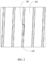
- Such a penetration is illustrated in Fig. 2 .
- the penetration 16 has approximately a 1 ⁇ 2 inch (1.27 cm) width (equal to the width of the membrane) and is elongate in a direction parallel to the steam pipes. Elongating the penetration in this way helps somewhat in terms of light collection efficiency.
- alignment and maintenance of alignment is significantly more difficult than required with a 2 inch (5.08 cm) penetration supported by the tube bend approach.
- the lateral alignment tolerance assuming a 15 meter wide boiler, is approximately 1.25 cm over 14 meters, or approximately 0.8 milliradians. In order to provide required alignment resolution, an alignment increment at least a factor of 10 smaller (i.e., 0.08 milliradians) is required. These tolerances cannot be achieved with the method and apparatus described in US 7 469 092 B2 .
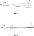
- a modified pitch optic and catch optic configuration are required. Such a configuration is illustrated in Figs. 3 and 4 .
- the collimating lens 18 is mounted to a tilt stage 19 allowing it to be tilted along orthogonal 90° axes as described in greater detail below and in U.S. Patent No. 7,469,092 .
- a relay lens 20 is provided in optical communication with the collimating lens 18. The relay lens is aligned during construction on the axis of the slotted membrane penetration. As a result, the beam received by the relay lens must go through the slotted penetration 16 at what is the focal point of the relay lens. See Fig. 4 .
- the angle that the beam goes through the slotted penetration can be adjusted in two dimensions by steering the beam from the collimating lens to different locations on the relay lens. This allows the beam to be steered through the slotted penetration at the pitch side to hit the slotted penetration at the catch side of the boiler.
- the catch optics incorporate a relay lens 20 and tilt collimating lens 18 in the same manner depicted in Figs. 3 and 4 .
- Use of the tilt stage on the catch collimating lens ensures a maximum strength collimated received beam is conveyed to an optically coupled multi-mode fiber.
- the pitch beam is collimated to a diameter of about 5 mm, as opposed to on the order of 20 mm in prior art systems.
- Fig. 5 schematically illustrates an embodiment of alignable pitch and catch optics.
- the transmitter and receiver are similar in design: the transmitter generates a collimated beam of laser light emerging from an optical fiber, and the receiver captures a collimated beam of light and focuses it into a fiber. (It is possible to send the light backward through this optical system, and most of the elements of the transmitter and receiver are identical.) The following description applies to either the transmitter or receiver module.
- the pitch and catch optics may be mounted in a housing 100 with the leading side 102 having an orifice 104 occupied by relay lens 20.
- the housing may be an NEMA-4 enclosure to protect the pitch and catch optics from the environment.
- a collimating lens 18 is attached to a kinematic tilt stage 106 positioned to tip and tilt the collimating lens 18 about orthogonal axes perpendicular to an optical axis of the pitch optics.
- Two direct drive stepper motors 108 accomplish the tip and tilt. These motors are controlled by a computer via an Ethernet or similar connection. This connection may be through an optical fiber in order to avoid electrical interference.
- the stepper motors 108 hold their positions when power is removed, so optical alignment is not effected by power outages.
- the stepper motors are driven by a motor drive 110.
- the control computer monitors the amount of laser light that is transmitted and detected.
- a discrete alignment wavelength such as a visible or near-infrared light may be provided for continuous or periodic alignment proceedings. Any misalignment will reduce this detected signal.
- the computer measure the detected signal, directs one of the two stepper motors to move a small amount in one direction, then re-measures the detected signal. If the signal increases, the computer directs the stepper motor to move again in the same direction until the signal does not increase. The computer then directs the other stepper motor to move along the orthogonal axis to maximize the detected signal, then repeats the whole process for the other sensor head. As the detected signal increases, the detector amplifier gain automatically decreases so that the auto-alignment proceeds over several iterations of signal size.
- the auto-alignment system can function with detected powers from nanowatts to milliwatts.
- This "hill-climbing" algorithm is able to align the system after near-total loss of signal, in the presence of substantial noise, and is tolerant of beam blockages, power outages, mechanical shocks and other disturbances that could cause other alignment systems to misalign to the limits of the control electronics. All that is required for auto alignment is a finite signal with a global maximum in position space. Depending on the specific installation conditions, auto-alignment may occur periodically at set intervals such as every hour or as needed after an extended period, such as days of operation. The control computer may monitor the directed signal and auto-align only when the signal drops below a preset threshold.
- a sight tube 112 has a proximal and a distal end.
- the proximal end is attached to extend normally from an exterior wall 114 of the boiler with an elongate penetration 16 communicating with the interior of the sight tube 112.
- a flange 116 is provided at a distal end of the sight tube 112. The flange 116 allows the housing 100 to be attached with the leading end 102 abutting the boiler flange with the relay lens 20 in optical communication with the penetration 16. In this manner a beam may be transmitted into the boiler interior 118 through the penetration 16 and across the boiler to a receiver containing catch optics substantially identical to those described above with regard to Fig. 5 .
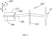
- Fig. 6 illustrates an alternative embodiment of alignable pitch and catch optics 200.
- Fig. 6 will be described as a transmitter and a receiver is of similar design.
- a lens 202 is optically coupled to an optical fiber 204.
- the lens 202 is referred to herein as a "collimating" lens and may be a true collimating lens (that produces a beam of substantially constant diameter).
- the collimating lens 202 may be a "near" collimating lens that provides a slight expansion of the beam 206.
- the fiber 204 and the lens 202 are mechanically linked together in a fixed relationship and movable by "translation" along orthogonal X-Y axes 208 by a translation mechanism 210.
- the emitted beam 206 is movable by translation to strike select portions of the relay lens 212 which directs the beam through the membrane slot and focuses the beam at about the receive or catch optic (corresponding to the lens 202 of the catch optic).
- Stepper motors, a computer controller and a "hill climbing" algorithm similar to that discussed above with respect to the embodiment of Fig. 5 are operatively associated with the translation mechanism 210 to provide for substantially continuous alignment correction.
Landscapes
- Engineering & Computer Science (AREA)
- Physics & Mathematics (AREA)
- Chemical & Material Sciences (AREA)
- General Physics & Mathematics (AREA)
- Combustion & Propulsion (AREA)
- Mechanical Engineering (AREA)
- General Engineering & Computer Science (AREA)
- Biochemistry (AREA)
- Life Sciences & Earth Sciences (AREA)
- Analytical Chemistry (AREA)
- Health & Medical Sciences (AREA)
- General Health & Medical Sciences (AREA)
- Immunology (AREA)
- Pathology (AREA)
- Spectroscopy & Molecular Physics (AREA)
- Optics & Photonics (AREA)
- Investigating Or Analysing Materials By Optical Means (AREA)
- Thermal Sciences (AREA)
- Photometry And Measurement Of Optical Pulse Characteristics (AREA)
- Control Of Combustion (AREA)
Priority Applications (1)
| Application Number | Priority Date | Filing Date | Title |
|---|---|---|---|
| PL10729501T PL2376840T3 (pl) | 2009-01-09 | 2010-01-07 | Sposób i urządzenie do monitorowania właściwości spalania we wnętrzu kotła |
Applications Claiming Priority (3)
| Application Number | Priority Date | Filing Date | Title |
|---|---|---|---|
| US14373209P | 2009-01-09 | 2009-01-09 | |
| US14438409P | 2009-01-13 | 2009-01-13 | |
| PCT/US2010/020345 WO2010080892A2 (en) | 2009-01-09 | 2010-01-07 | Method and apparatus for monitoring combustion properties in an interior of a boiler |
Publications (3)
| Publication Number | Publication Date |
|---|---|
| EP2376840A2 EP2376840A2 (en) | 2011-10-19 |
| EP2376840A4 EP2376840A4 (en) | 2013-12-25 |
| EP2376840B1 true EP2376840B1 (en) | 2018-10-31 |
Family
ID=42317130
Family Applications (1)
| Application Number | Title | Priority Date | Filing Date |
|---|---|---|---|
| EP10729501.6A Active EP2376840B1 (en) | 2009-01-09 | 2010-01-07 | Method and apparatus for monitoring combustion properties in an interior of a boiler |
Country Status (11)
| Country | Link |
|---|---|
| US (1) | US8786856B2 (zh) |
| EP (1) | EP2376840B1 (zh) |
| JP (1) | JP5576399B2 (zh) |
| KR (1) | KR101674694B1 (zh) |
| CN (1) | CN102308150B (zh) |
| AU (1) | AU2010203674B2 (zh) |
| CA (1) | CA2748793C (zh) |
| DK (1) | DK2376840T3 (zh) |
| ES (1) | ES2704840T3 (zh) |
| PL (1) | PL2376840T3 (zh) |
| WO (1) | WO2010080892A2 (zh) |
Families Citing this family (7)
| Publication number | Priority date | Publication date | Assignee | Title |
|---|---|---|---|---|
| JP6196289B2 (ja) * | 2012-04-19 | 2017-09-13 | ゾロ テクノロジーズ,インコーポレイティド | 方向可変の波長可変ダイオードレーザ吸収分光計を有する炉内再帰反射体 |
| CN105917170B (zh) * | 2013-12-20 | 2019-12-24 | 约翰·尊科股份有限公司 | 在恶劣环境下监测在tdlas测量中的端口堵塞的方法和装置 |
| CN105444201B (zh) | 2014-09-26 | 2018-11-13 | 通用电气公司 | 燃烧优化的方法及其系统 |
| CN104390802A (zh) * | 2014-11-22 | 2015-03-04 | 山东省特种设备检验研究院 | 承压设备检测方法及其专用承压设备检测装置 |
| CN106017725B (zh) * | 2016-05-26 | 2019-07-09 | 中国人民解放军战略支援部队航天工程大学 | 一种适用于燃烧流场气体二维重建的测量装置 |
| CN107703098A (zh) * | 2017-10-12 | 2018-02-16 | 中国能源建设集团科技发展有限公司 | 锅炉炉膛氮氧化物测量装置 |
| DE102021121860A1 (de) * | 2021-08-24 | 2023-03-02 | Vaillant Gmbh | Verfahren zur Inspektion und Überwachung eines Heizgerätes, unter Verwendung eines sensorisch erzeugten Abbildes |
Family Cites Families (101)
| Publication number | Priority date | Publication date | Assignee | Title |
|---|---|---|---|---|
| US2841122A (en) * | 1953-03-12 | 1958-07-01 | Babcock & Wilcox Co | Wall tube fluid heater with a releasably anchored enclosure |
| US3754533A (en) * | 1971-11-24 | 1973-08-28 | Babcock & Wilcox Ltd | Tube support system |
| US4037113A (en) | 1975-04-11 | 1977-07-19 | Forney Engineering Company | Flame detector |
| US4028081A (en) | 1975-12-11 | 1977-06-07 | Bell Telephone Laboratories, Incorporated | Method for manufacturing helical optical fiber |
| US4011403A (en) | 1976-03-30 | 1977-03-08 | Northwestern University | Fiber optic laser illuminators |
| US4305640A (en) | 1978-11-24 | 1981-12-15 | National Research Development Corporation | Laser beam annealing diffuser |
| US4360372A (en) | 1980-11-10 | 1982-11-23 | Northern Telecom Limited | Fiber optic element for reducing speckle noise |
| US4432286A (en) * | 1982-05-19 | 1984-02-21 | The United States Of America As Represented By The United States Department Of Energy | Combustion pinhole camera system |
| DD219059A3 (de) * | 1982-09-14 | 1985-02-20 | Freiberg Brennstoffinst | Periskop fuer hochtemperatur-reaktoren |
| US4672198A (en) | 1986-01-24 | 1987-06-09 | At&T Company And At&T Bell Laboratories | Signal sampler microbending fiber test clip |
| JPS63133035A (ja) * | 1986-11-26 | 1988-06-04 | Anritsu Corp | 光伝送特性試験装置 |
| US4915468A (en) | 1987-02-20 | 1990-04-10 | The Board Of Trustees Of The Leland Stanford Junior University | Apparatus using two-mode optical waveguide with non-circular core |
| US4741586A (en) | 1987-02-20 | 1988-05-03 | The Board Of Trustees Of The Leland Stanford Junior University | Dynamic coupler using two-mode optical waveguides |
| US4989979A (en) | 1989-01-17 | 1991-02-05 | Board Of Regents, The University Of Texas System | Optical fiber sensors with full common-mode compensation and measurand sensitivity enhancement |
| EP0435825B1 (de) | 1989-12-27 | 1996-01-17 | Ciba-Geigy Ag | Vorrichtung zum Homogenisieren der inhomogenen Lichtverteilung eines Laserstrahllichtbündels |
| US5042905A (en) | 1990-06-15 | 1991-08-27 | Honeywell Inc. | Electrically passive fiber optic position sensor |
| IT1251246B (it) | 1991-08-27 | 1995-05-05 | Sie Systems Spa | Dispositivo per a rivelazione della presenza e della qualita' della fiamma attraverso la captazione e l'analisi di radiazioni elettromagnetiche di diversa lunghezza d'onda |
| US5436444A (en) | 1991-12-06 | 1995-07-25 | Alamed Corporation | Multimode optical fiber motion monitor with audible output |
| US5291013A (en) | 1991-12-06 | 1994-03-01 | Alamed Corporation | Fiber optical monitor for detecting normal breathing and heartbeat motion based on changes in speckle patterns |
| FI90469C (fi) * | 1992-02-25 | 1994-02-10 | Imatran Voima Oy | Sovitelma tulipesäkamerassa |
| US5468239A (en) | 1992-04-13 | 1995-11-21 | Sorenson Laboratories, Inc. | Apparatus and methods for using a circumferential light-emitting surgical laser probe |
| WO1993022706A1 (en) | 1992-04-28 | 1993-11-11 | The Furukawa Electric Co., Ltd. | External modulator for optical communication |
| US5298047A (en) | 1992-08-03 | 1994-03-29 | At&T Bell Laboratories | Method of making a fiber having low polarization mode dispersion due to a permanent spin |
| US5798840A (en) | 1992-08-05 | 1998-08-25 | The Aerospace Corporation | Fast optical absorption tomography apparatus and method |
| GB9217705D0 (en) | 1992-08-20 | 1992-09-30 | Ici Plc | Data-recordal using laser beams |
| WO1994011708A1 (en) | 1992-11-06 | 1994-05-26 | Martin Marietta Corporation | Interferometric optical sensor read-out system |
| US5408554A (en) | 1993-12-17 | 1995-04-18 | Porta System Corporation | Fiber optic coupling |
| US5448071A (en) | 1993-04-16 | 1995-09-05 | Bruce W. McCaul | Gas spectroscopy |
| JPH06331543A (ja) * | 1993-05-24 | 1994-12-02 | Fuji Electric Co Ltd | 浮遊粒子濃度計測装置 |
| US5396506A (en) | 1993-12-09 | 1995-03-07 | United Technologies Corporation | Coupled multiple output fiber laser |
| CN1163665A (zh) | 1994-12-23 | 1997-10-29 | 西门子公司 | 利用法拉第效应、带有对强度变化和温度影响进行补偿的测量磁场的方法和装置 |
| DE4446425A1 (de) | 1994-12-23 | 1996-06-27 | Siemens Ag | Verfahren und Anordnung zum Messen eines Magnetfeldes unter Ausnutzung des Faraday-Effekts mit Kompensation von Intensitätsänderungen und Temperatureinflüssen |
| DE19549395A1 (de) | 1995-02-07 | 1996-10-31 | Ldt Gmbh & Co | Bilderzeugungssysteme zur Bestimmung von Sehfehlern an Probanden und für deren Therapie |
| US5598264A (en) | 1995-05-18 | 1997-01-28 | Failes; Michael | Noise compensated interferometric measuring device and method using signal and reference interferometers |
| JPH0915447A (ja) * | 1995-06-30 | 1997-01-17 | Oki Electric Ind Co Ltd | 光ファイバーコリメータの固定構造及び方法 |
| US5621213A (en) | 1995-07-07 | 1997-04-15 | Novitron International Inc. | System and method for monitoring a stack gas |
| JP3860237B2 (ja) | 1995-07-26 | 2006-12-20 | 富士通株式会社 | 偏波分散の抑圧特性を持つ光ファイバ及びその製造方法 |
| WO1997007067A1 (en) | 1995-08-16 | 1997-02-27 | Plasma Optical Fibre B.V. | Optical fiber with low polarisation mode dispersion |
| JPH0973020A (ja) | 1995-09-05 | 1997-03-18 | Toshiba Corp | 光合分波器 |
| EP0766080A1 (en) | 1995-09-29 | 1997-04-02 | FINMECCANICA S.p.A. AZIENDA ANSALDO | System and method for monitoring combustion and pollutants by means of laser diodes |
| JPH09152126A (ja) * | 1995-11-30 | 1997-06-10 | Tokyo Gas Co Ltd | 火炎検知装置 |
| US5742715A (en) | 1995-12-21 | 1998-04-21 | Lucent Technologies Inc. | Optical fiber status analyzer and related methods |
| GB2309317A (en) | 1996-01-17 | 1997-07-23 | Univ Southampton | Optical fibre device |
| US5732166A (en) | 1996-03-11 | 1998-03-24 | Hamann; Oliver | High temperature-resistant optical sensing apparatus and method of making |
| WO1998008077A1 (de) | 1996-08-16 | 1998-02-26 | Novartis Ag | Optische detektionsvorrichtung |
| US6169830B1 (en) | 1996-08-26 | 2001-01-02 | Arroyo Optics, Inc. | Methods of fabricating grating assisted coupler devices |
| US5805318A (en) | 1996-11-04 | 1998-09-08 | Honeywell Inc. | Apparatus for determining the effect of modal noise on a communication system by flexing an optical fiber |
| US5841915A (en) | 1996-11-04 | 1998-11-24 | Honeywell Inc. | Apparatus for determining the effect of modal noise on a communication system by affecting an optical fiber discontinuity |
| GB2320155B (en) | 1996-12-03 | 2000-11-01 | Chelsea Instr Ltd | Method and apparatus for the imaging of gases |
| US6046809A (en) | 1998-02-04 | 2000-04-04 | S3 Incorporated | Real-time in situ multiple gas species sensing method |
| JPH113534A (ja) * | 1997-04-14 | 1999-01-06 | Toray Ind Inc | 光記録装置および光記録媒体 |
| JPH10301153A (ja) | 1997-04-23 | 1998-11-13 | Sony Corp | 光源装置とこれを用いた光学測定装置および露光装置 |
| US6124597A (en) | 1997-07-07 | 2000-09-26 | Cedars-Sinai Medical Center | Method and devices for laser induced fluorescence attenuation spectroscopy |
| US6016372A (en) | 1997-10-16 | 2000-01-18 | World Precision Instruments, Inc. | Chemical sensing techniques employing liquid-core optical fibers |
| US5930029A (en) | 1997-12-02 | 1999-07-27 | Sdl, Inc. | Optical fiber amplifier with optimized power conversion |
| US5960129A (en) | 1997-12-22 | 1999-09-28 | Bayer Corporation | Method and apparatus for detecting liquid and gas segment flow through a tube |
| WO1999045419A1 (en) | 1998-03-04 | 1999-09-10 | Sdl, Inc. | Optical couplers for multimode fibers |
| US6064417A (en) | 1998-03-31 | 2000-05-16 | Eastman Kodak Company | Laser printer using multiple sets of lasers with multiple wavelengths |
| WO1999053297A1 (en) | 1998-04-14 | 1999-10-21 | Instrumentarium Corporation | Sensor assembly and method for measuring nitrogen dioxide |
| JP4038631B2 (ja) * | 1998-08-28 | 2008-01-30 | 株式会社堀場製作所 | 半導体レーザ分光法を用いた温度・濃度・化学種の高速計測方法および計測システム |
| US6160255A (en) | 1998-10-05 | 2000-12-12 | The United States Of America As Represented By The Secretary Of The Army | Laser-based photoacoustic sensor and method for trace detection and differentiantion of atmospheric NO and NO2 |
| JP2000121558A (ja) * | 1998-10-16 | 2000-04-28 | Mitsubishi Heavy Ind Ltd | 計測装置 |
| DE19847832C1 (de) * | 1998-10-16 | 1999-11-04 | Siemens Ag | Verfahren zum Überwachen eines optischen Systems mit einer unmittelbar an einem Verbrennungsraum angeordneten Frontlinse und Überwachungsmodul |
| AU1060100A (en) | 1998-11-11 | 2000-05-29 | University Of Manchester Institute Of Science & Technology, The | Chemical species distribution and mixture monitoring |
| US6510265B1 (en) | 1999-04-21 | 2003-01-21 | Lucent Technologies Inc. | High-speed multi mode fiber optic link |
| US6042365A (en) | 1999-06-28 | 2000-03-28 | Chen; Yaosheng | Fuel combustion monitoring apparatus and method |
| US6396056B1 (en) | 1999-07-08 | 2002-05-28 | Air Instruments And Measurements, Inc. | Gas detectors and gas analyzers utilizing spectral absorption |
| US6415080B1 (en) | 1999-09-03 | 2002-07-02 | Zolo Technologies, Inc. | Echelle grating dense wavelength division multiplexer/demultiplexer |
| US6351587B1 (en) | 1999-11-12 | 2002-02-26 | Lucent Technologies Inc. | Multi-fiber digital delay line |
| US6422043B1 (en) | 1999-11-16 | 2002-07-23 | Fitel Usa Corp. | Method of making an improved multimode optical fiber and fiber made by method |
| CA2398029A1 (en) | 2000-02-08 | 2001-08-16 | Cornell Research Foundation, Inc. | Multiphoton excitation through optical fibers for fluorescence spectroscopy |
| US6363190B1 (en) | 2000-02-11 | 2002-03-26 | New Focus, Inc. | Polarization insensitive fused fiber coupler method and apparatus |
| US20020031737A1 (en) | 2000-03-10 | 2002-03-14 | American Air Liquide, Inc. | Method for continuously monitoring chemical species and temperature in hot process gases |
| KR100353442B1 (ko) | 2000-03-22 | 2002-09-19 | 삼성전자 주식회사 | 산란 손실이 감소된 다중모드 광섬유 구조 |
| US6455851B1 (en) | 2000-03-28 | 2002-09-24 | Air Instruments And Measurement, Inc. | Spectroscopic remote sensing exhaust emission monitoring system |
| US6385372B1 (en) | 2000-04-19 | 2002-05-07 | Tera Fiberoptics, Inc. | Fiber optical coupler fabrication and system |
| CN1195202C (zh) | 2000-09-15 | 2005-03-30 | 饶云江 | 集成式光纤应变与温度传感器装置 |
| US6519385B1 (en) | 2000-09-27 | 2003-02-11 | The Boeing Company | Method and apparatus for controllably positioning an optical fiber to introduce a phase shift |
| US6959129B2 (en) | 2000-12-22 | 2005-10-25 | Metrophotonics Inc. | Bidirectional multiplexer and demultiplexer based on a single echelle waveguide grating |
| US20020158202A1 (en) | 2001-01-08 | 2002-10-31 | Webber Michael E. | Laser-based sensor for measuring combustion parameters |
| US6701753B2 (en) | 2001-02-11 | 2004-03-09 | Fitel Usa Corp. | Method and apparatus for making improved optical fiber preforms and optical fiber therefrom |
| US6766070B2 (en) | 2001-04-27 | 2004-07-20 | The United States Of America As Represented By The Secretary Of The Navy | High power fiber optic modulator system and method |
| JP2003004633A (ja) | 2001-06-22 | 2003-01-08 | Nissan Motor Co Ltd | エンジンの燃料濃度測定装置 |
| US6950452B2 (en) | 2001-09-28 | 2005-09-27 | The Furukawa Electric Co., Ltd. | Semiconductor laser module and method for simultaneously reducing relative intensity noise (RIN) and stimulated brillouin scattering (SBS) |
| KR100417000B1 (ko) | 2001-12-03 | 2004-02-05 | 삼성전자주식회사 | 저 편광 모드 분산을 위한 장치 |
| JP2004096088A (ja) | 2002-07-10 | 2004-03-25 | Fuji Photo Film Co Ltd | 合波レーザー光源および露光装置 |
| WO2004050573A1 (en) | 2002-09-25 | 2004-06-17 | Giacomo Stefano Roba | Process for producing an optical fiber having a low polarization mode dispersion |
| JP2004117236A (ja) * | 2002-09-27 | 2004-04-15 | Fuji Photo Film Co Ltd | 光学特性測定装置 |
| JP2008500839A (ja) | 2002-11-18 | 2008-01-17 | ヴァージニア テック インテレクチュアル プロパティーズ インク | 摂動検出システム、装置及び方法 |
| KR100469736B1 (ko) | 2002-11-21 | 2005-02-02 | 삼성전자주식회사 | 다파장 레이징 광원에 파장 잠김된 페브리-페롯 레이저장치 및 이를 이용한 광 전송장치 |
| US20040160596A1 (en) | 2003-02-19 | 2004-08-19 | Pactonix, Inc. | Apparatus and method to accurately monitor signal quality in optical signal transmission systems |
| CN100437165C (zh) | 2003-03-31 | 2008-11-26 | 佐勒技术公司 | 监视与控制燃烧过程的方法与设备 |
| JP2004354671A (ja) | 2003-05-29 | 2004-12-16 | Nikon Corp | スペックルパターン分散装置及びレーザ光照射装置 |
| ES2325621T3 (es) | 2003-12-30 | 2009-09-10 | Prysmian S.P.A. | Enlace de fibra optica de baja dispersion de modo de polarizacion (pmd) y procedimiento para su fabricacion. |
| US7158552B2 (en) | 2004-02-13 | 2007-01-02 | Lucent Technologies Inc. | Low relative intensity noise fiber grating type laser diode |
| US7787728B2 (en) | 2004-03-31 | 2010-08-31 | Zolo Technologies, Inc. | Optical mode noise averaging device |
| US7724413B2 (en) | 2005-07-11 | 2010-05-25 | Mitsubishi Electric Corporation | Speckle removing light source and lighting apparatus |
| JP5180088B2 (ja) * | 2005-11-04 | 2013-04-10 | ゾロ テクノロジーズ,インコーポレイティド | ガスタービンエンジンの燃焼器内における分光測定の方法及び装置 |
| JP4446195B2 (ja) * | 2005-12-19 | 2010-04-07 | 富士電機ホールディングス株式会社 | レーザ光出力部、レーザ光入力部およびレーザ式ガス分析計 |
| JP2011158384A (ja) | 2010-02-02 | 2011-08-18 | Seiko Epson Corp | 微粒子検出装置 |
| CN101988845B (zh) | 2010-07-30 | 2012-04-18 | 西安理工大学 | 采用激光曲面镜反射进行熔硅液位检测的装置及检测方法 |
-
2010
- 2010-01-07 CA CA2748793A patent/CA2748793C/en active Active
- 2010-01-07 AU AU2010203674A patent/AU2010203674B2/en active Active
- 2010-01-07 ES ES10729501T patent/ES2704840T3/es active Active
- 2010-01-07 KR KR1020117015677A patent/KR101674694B1/ko active IP Right Grant
- 2010-01-07 CN CN201080006508.2A patent/CN102308150B/zh active Active
- 2010-01-07 JP JP2011545421A patent/JP5576399B2/ja active Active
- 2010-01-07 DK DK10729501.6T patent/DK2376840T3/en active
- 2010-01-07 EP EP10729501.6A patent/EP2376840B1/en active Active
- 2010-01-07 US US13/142,791 patent/US8786856B2/en active Active
- 2010-01-07 WO PCT/US2010/020345 patent/WO2010080892A2/en active Application Filing
- 2010-01-07 PL PL10729501T patent/PL2376840T3/pl unknown
Non-Patent Citations (1)
| Title |
|---|
| None * |
Also Published As
| Publication number | Publication date |
|---|---|
| AU2010203674A2 (en) | 2012-01-19 |
| US20110300492A1 (en) | 2011-12-08 |
| US8786856B2 (en) | 2014-07-22 |
| JP2012514755A (ja) | 2012-06-28 |
| EP2376840A2 (en) | 2011-10-19 |
| WO2010080892A2 (en) | 2010-07-15 |
| CN102308150B (zh) | 2014-01-01 |
| DK2376840T3 (en) | 2019-02-04 |
| CA2748793A1 (en) | 2010-07-15 |
| JP5576399B2 (ja) | 2014-08-20 |
| PL2376840T3 (pl) | 2019-04-30 |
| CA2748793C (en) | 2016-06-07 |
| AU2010203674A1 (en) | 2011-07-28 |
| ES2704840T3 (es) | 2019-03-20 |
| WO2010080892A3 (en) | 2010-09-02 |
| KR101674694B1 (ko) | 2016-11-09 |
| AU2010203674B2 (en) | 2014-09-25 |
| CN102308150A (zh) | 2012-01-04 |
| KR20110120863A (ko) | 2011-11-04 |
| EP2376840A4 (en) | 2013-12-25 |
Similar Documents
| Publication | Publication Date | Title |
|---|---|---|
| EP2376840B1 (en) | Method and apparatus for monitoring combustion properties in an interior of a boiler | |
| US7248755B2 (en) | Method and apparatus for the monitoring and control of combustion | |
| US10948184B2 (en) | Method and apparatus for monitoring port blockage for TDLAS measurements in harsh environments |
Legal Events
| Date | Code | Title | Description |
|---|---|---|---|
| PUAI | Public reference made under article 153(3) epc to a published international application that has entered the european phase |
Free format text: ORIGINAL CODE: 0009012 |
|
| 17P | Request for examination filed |
Effective date: 20110708 |
|
| AK | Designated contracting states |
Kind code of ref document: A2 Designated state(s): AT BE BG CH CY CZ DE DK EE ES FI FR GB GR HR HU IE IS IT LI LT LU LV MC MK MT NL NO PL PT RO SE SI SK SM TR |
|
| DAX | Request for extension of the european patent (deleted) | ||
| A4 | Supplementary search report drawn up and despatched |
Effective date: 20131127 |
|
| RIC1 | Information provided on ipc code assigned before grant |
Ipc: F23N 5/08 20060101AFI20131121BHEP Ipc: F24H 9/20 20060101ALI20131121BHEP Ipc: F23M 5/08 20060101ALI20131121BHEP Ipc: G01N 21/84 20060101ALI20131121BHEP Ipc: G01N 21/00 20060101ALI20131121BHEP Ipc: G01N 21/39 20060101ALI20131121BHEP |
|
| RAP1 | Party data changed (applicant data changed or rights of an application transferred) |
Owner name: JOHN ZINK COMPANY, LLC |
|
| GRAP | Despatch of communication of intention to grant a patent |
Free format text: ORIGINAL CODE: EPIDOSNIGR1 |
|
| STAA | Information on the status of an ep patent application or granted ep patent |
Free format text: STATUS: GRANT OF PATENT IS INTENDED |
|
| INTG | Intention to grant announced |
Effective date: 20180614 |
|
| GRAS | Grant fee paid |
Free format text: ORIGINAL CODE: EPIDOSNIGR3 |
|
| GRAA | (expected) grant |
Free format text: ORIGINAL CODE: 0009210 |
|
| STAA | Information on the status of an ep patent application or granted ep patent |
Free format text: STATUS: THE PATENT HAS BEEN GRANTED |
|
| AK | Designated contracting states |
Kind code of ref document: B1 Designated state(s): AT BE BG CH CY CZ DE DK EE ES FI FR GB GR HR HU IE IS IT LI LT LU LV MC MK MT NL NO PL PT RO SE SI SK SM TR |
|
| REG | Reference to a national code |
Ref country code: CH Ref legal event code: EP Ref country code: GB Ref legal event code: FG4D |
|
| REG | Reference to a national code |
Ref country code: AT Ref legal event code: REF Ref document number: 1059847 Country of ref document: AT Kind code of ref document: T Effective date: 20181115 |
|
| REG | Reference to a national code |
Ref country code: DE Ref legal event code: R096 Ref document number: 602010054751 Country of ref document: DE |
|
| REG | Reference to a national code |
Ref country code: IE Ref legal event code: FG4D |
|
| REG | Reference to a national code |
Ref country code: DK Ref legal event code: T3 Effective date: 20190128 |
|
| REG | Reference to a national code |
Ref country code: NL Ref legal event code: FP |
|
| REG | Reference to a national code |
Ref country code: SE Ref legal event code: TRGR |
|
| REG | Reference to a national code |
Ref country code: LT Ref legal event code: MG4D |
|
| REG | Reference to a national code |
Ref country code: ES Ref legal event code: FG2A Ref document number: 2704840 Country of ref document: ES Kind code of ref document: T3 Effective date: 20190320 |
|
| PG25 | Lapsed in a contracting state [announced via postgrant information from national office to epo] |
Ref country code: LV Free format text: LAPSE BECAUSE OF FAILURE TO SUBMIT A TRANSLATION OF THE DESCRIPTION OR TO PAY THE FEE WITHIN THE PRESCRIBED TIME-LIMIT Effective date: 20181031 Ref country code: IS Free format text: LAPSE BECAUSE OF FAILURE TO SUBMIT A TRANSLATION OF THE DESCRIPTION OR TO PAY THE FEE WITHIN THE PRESCRIBED TIME-LIMIT Effective date: 20190228 Ref country code: BG Free format text: LAPSE BECAUSE OF FAILURE TO SUBMIT A TRANSLATION OF THE DESCRIPTION OR TO PAY THE FEE WITHIN THE PRESCRIBED TIME-LIMIT Effective date: 20190131 Ref country code: HR Free format text: LAPSE BECAUSE OF FAILURE TO SUBMIT A TRANSLATION OF THE DESCRIPTION OR TO PAY THE FEE WITHIN THE PRESCRIBED TIME-LIMIT Effective date: 20181031 Ref country code: NO Free format text: LAPSE BECAUSE OF FAILURE TO SUBMIT A TRANSLATION OF THE DESCRIPTION OR TO PAY THE FEE WITHIN THE PRESCRIBED TIME-LIMIT Effective date: 20190131 Ref country code: LT Free format text: LAPSE BECAUSE OF FAILURE TO SUBMIT A TRANSLATION OF THE DESCRIPTION OR TO PAY THE FEE WITHIN THE PRESCRIBED TIME-LIMIT Effective date: 20181031 |
|
| PG25 | Lapsed in a contracting state [announced via postgrant information from national office to epo] |
Ref country code: GR Free format text: LAPSE BECAUSE OF FAILURE TO SUBMIT A TRANSLATION OF THE DESCRIPTION OR TO PAY THE FEE WITHIN THE PRESCRIBED TIME-LIMIT Effective date: 20190201 Ref country code: PT Free format text: LAPSE BECAUSE OF FAILURE TO SUBMIT A TRANSLATION OF THE DESCRIPTION OR TO PAY THE FEE WITHIN THE PRESCRIBED TIME-LIMIT Effective date: 20190301 |
|
| PG25 | Lapsed in a contracting state [announced via postgrant information from national office to epo] |
Ref country code: CZ Free format text: LAPSE BECAUSE OF FAILURE TO SUBMIT A TRANSLATION OF THE DESCRIPTION OR TO PAY THE FEE WITHIN THE PRESCRIBED TIME-LIMIT Effective date: 20181031 |
|
| REG | Reference to a national code |
Ref country code: DE Ref legal event code: R097 Ref document number: 602010054751 Country of ref document: DE |
|
| PG25 | Lapsed in a contracting state [announced via postgrant information from national office to epo] |
Ref country code: SK Free format text: LAPSE BECAUSE OF FAILURE TO SUBMIT A TRANSLATION OF THE DESCRIPTION OR TO PAY THE FEE WITHIN THE PRESCRIBED TIME-LIMIT Effective date: 20181031 Ref country code: RO Free format text: LAPSE BECAUSE OF FAILURE TO SUBMIT A TRANSLATION OF THE DESCRIPTION OR TO PAY THE FEE WITHIN THE PRESCRIBED TIME-LIMIT Effective date: 20181031 Ref country code: SM Free format text: LAPSE BECAUSE OF FAILURE TO SUBMIT A TRANSLATION OF THE DESCRIPTION OR TO PAY THE FEE WITHIN THE PRESCRIBED TIME-LIMIT Effective date: 20181031 Ref country code: EE Free format text: LAPSE BECAUSE OF FAILURE TO SUBMIT A TRANSLATION OF THE DESCRIPTION OR TO PAY THE FEE WITHIN THE PRESCRIBED TIME-LIMIT Effective date: 20181031 Ref country code: MC Free format text: LAPSE BECAUSE OF FAILURE TO SUBMIT A TRANSLATION OF THE DESCRIPTION OR TO PAY THE FEE WITHIN THE PRESCRIBED TIME-LIMIT Effective date: 20181031 |
|
| REG | Reference to a national code |
Ref country code: CH Ref legal event code: PL |
|
| PLBE | No opposition filed within time limit |
Free format text: ORIGINAL CODE: 0009261 |
|
| STAA | Information on the status of an ep patent application or granted ep patent |
Free format text: STATUS: NO OPPOSITION FILED WITHIN TIME LIMIT |
|
| PG25 | Lapsed in a contracting state [announced via postgrant information from national office to epo] |
Ref country code: LU Free format text: LAPSE BECAUSE OF NON-PAYMENT OF DUE FEES Effective date: 20190107 |
|
| 26N | No opposition filed |
Effective date: 20190801 |
|
| REG | Reference to a national code |
Ref country code: BE Ref legal event code: MM Effective date: 20190131 |
|
| REG | Reference to a national code |
Ref country code: IE Ref legal event code: MM4A |
|
| PG25 | Lapsed in a contracting state [announced via postgrant information from national office to epo] |
Ref country code: SI Free format text: LAPSE BECAUSE OF FAILURE TO SUBMIT A TRANSLATION OF THE DESCRIPTION OR TO PAY THE FEE WITHIN THE PRESCRIBED TIME-LIMIT Effective date: 20181031 |
|
| PG25 | Lapsed in a contracting state [announced via postgrant information from national office to epo] |
Ref country code: BE Free format text: LAPSE BECAUSE OF NON-PAYMENT OF DUE FEES Effective date: 20190131 |
|
| PG25 | Lapsed in a contracting state [announced via postgrant information from national office to epo] |
Ref country code: LI Free format text: LAPSE BECAUSE OF NON-PAYMENT OF DUE FEES Effective date: 20190131 Ref country code: CH Free format text: LAPSE BECAUSE OF NON-PAYMENT OF DUE FEES Effective date: 20190131 |
|
| PG25 | Lapsed in a contracting state [announced via postgrant information from national office to epo] |
Ref country code: IE Free format text: LAPSE BECAUSE OF NON-PAYMENT OF DUE FEES Effective date: 20190107 |
|
| PG25 | Lapsed in a contracting state [announced via postgrant information from national office to epo] |
Ref country code: MT Free format text: LAPSE BECAUSE OF NON-PAYMENT OF DUE FEES Effective date: 20190107 |
|
| REG | Reference to a national code |
Ref country code: FI Ref legal event code: PCE Owner name: ONPOINT TECHNOLOGIES, LLC |
|
| REG | Reference to a national code |
Ref country code: ES Ref legal event code: PC2A Owner name: ONPOINT TECHNOLOGIES, LLC Effective date: 20201030 |
|
| REG | Reference to a national code |
Ref country code: DE Ref legal event code: R081 Ref document number: 602010054751 Country of ref document: DE Owner name: ONPOINT TECHNOLOGIES LLC (N.D.GES. D. STAATES , US Free format text: FORMER OWNER: JOHN ZINK COMPANY, LLC, TULSA, OKLA., US |
|
| REG | Reference to a national code |
Ref country code: NL Ref legal event code: PD Owner name: ONPOINT TECHNOLOGIES, LLC; US Free format text: DETAILS ASSIGNMENT: CHANGE OF OWNER(S), ASSIGNMENT; FORMER OWNER NAME: JOHN ZINK COMPANY, LLC Effective date: 20201117 |
|
| REG | Reference to a national code |
Ref country code: GB Ref legal event code: 732E Free format text: REGISTERED BETWEEN 20201210 AND 20201216 |
|
| PGFP | Annual fee paid to national office [announced via postgrant information from national office to epo] |
Ref country code: FR Payment date: 20201210 Year of fee payment: 12 |
|
| REG | Reference to a national code |
Ref country code: AT Ref legal event code: PC Ref document number: 1059847 Country of ref document: AT Kind code of ref document: T Owner name: ONPOINT TECHNOLOGIES, LLC, US Effective date: 20210118 |
|
| PGFP | Annual fee paid to national office [announced via postgrant information from national office to epo] |
Ref country code: IT Payment date: 20201211 Year of fee payment: 12 Ref country code: NL Payment date: 20210113 Year of fee payment: 12 Ref country code: FI Payment date: 20210224 Year of fee payment: 12 |
|
| PG25 | Lapsed in a contracting state [announced via postgrant information from national office to epo] |
Ref country code: CY Free format text: LAPSE BECAUSE OF FAILURE TO SUBMIT A TRANSLATION OF THE DESCRIPTION OR TO PAY THE FEE WITHIN THE PRESCRIBED TIME-LIMIT Effective date: 20181031 |
|
| PGFP | Annual fee paid to national office [announced via postgrant information from national office to epo] |
Ref country code: ES Payment date: 20210204 Year of fee payment: 12 Ref country code: PL Payment date: 20210105 Year of fee payment: 12 Ref country code: DK Payment date: 20210226 Year of fee payment: 12 Ref country code: SE Payment date: 20210226 Year of fee payment: 12 |
|
| REG | Reference to a national code |
Ref country code: AT Ref legal event code: UEP Ref document number: 1059847 Country of ref document: AT Kind code of ref document: T Effective date: 20181031 |
|
| PG25 | Lapsed in a contracting state [announced via postgrant information from national office to epo] |
Ref country code: HU Free format text: LAPSE BECAUSE OF FAILURE TO SUBMIT A TRANSLATION OF THE DESCRIPTION OR TO PAY THE FEE WITHIN THE PRESCRIBED TIME-LIMIT; INVALID AB INITIO Effective date: 20100107 |
|
| PG25 | Lapsed in a contracting state [announced via postgrant information from national office to epo] |
Ref country code: MK Free format text: LAPSE BECAUSE OF FAILURE TO SUBMIT A TRANSLATION OF THE DESCRIPTION OR TO PAY THE FEE WITHIN THE PRESCRIBED TIME-LIMIT Effective date: 20181031 |
|
| REG | Reference to a national code |
Ref country code: FI Ref legal event code: MAE |
|
| REG | Reference to a national code |
Ref country code: DK Ref legal event code: EBP Effective date: 20220131 |
|
| REG | Reference to a national code |
Ref country code: SE Ref legal event code: EUG |
|
| REG | Reference to a national code |
Ref country code: NL Ref legal event code: MM Effective date: 20220201 |
|
| PG25 | Lapsed in a contracting state [announced via postgrant information from national office to epo] |
Ref country code: SE Free format text: LAPSE BECAUSE OF NON-PAYMENT OF DUE FEES Effective date: 20220108 Ref country code: NL Free format text: LAPSE BECAUSE OF NON-PAYMENT OF DUE FEES Effective date: 20220201 Ref country code: FI Free format text: LAPSE BECAUSE OF NON-PAYMENT OF DUE FEES Effective date: 20220107 |
|
| PG25 | Lapsed in a contracting state [announced via postgrant information from national office to epo] |
Ref country code: FR Free format text: LAPSE BECAUSE OF NON-PAYMENT OF DUE FEES Effective date: 20220131 |
|
| PG25 | Lapsed in a contracting state [announced via postgrant information from national office to epo] |
Ref country code: IT Free format text: LAPSE BECAUSE OF NON-PAYMENT OF DUE FEES Effective date: 20220107 Ref country code: DK Free format text: LAPSE BECAUSE OF NON-PAYMENT OF DUE FEES Effective date: 20220131 |
|
| REG | Reference to a national code |
Ref country code: ES Ref legal event code: FD2A Effective date: 20230331 |
|
| PG25 | Lapsed in a contracting state [announced via postgrant information from national office to epo] |
Ref country code: ES Free format text: LAPSE BECAUSE OF NON-PAYMENT OF DUE FEES Effective date: 20220108 |
|
| PGFP | Annual fee paid to national office [announced via postgrant information from national office to epo] |
Ref country code: AT Payment date: 20221228 Year of fee payment: 14 |
|
| PG25 | Lapsed in a contracting state [announced via postgrant information from national office to epo] |
Ref country code: PL Free format text: LAPSE BECAUSE OF NON-PAYMENT OF DUE FEES Effective date: 20220107 |
|
| PGFP | Annual fee paid to national office [announced via postgrant information from national office to epo] |
Ref country code: TR Payment date: 20230106 Year of fee payment: 14 |
|
| P01 | Opt-out of the competence of the unified patent court (upc) registered |
Effective date: 20230528 |
|
| PGFP | Annual fee paid to national office [announced via postgrant information from national office to epo] |
Ref country code: GB Payment date: 20231130 Year of fee payment: 15 |
|
| PGFP | Annual fee paid to national office [announced via postgrant information from national office to epo] |
Ref country code: DE Payment date: 20231205 Year of fee payment: 15 |