EP2376817B1 - Plastic transmission cover, and gear-shift tower unit having the plastic transmission cover - Google Patents
Plastic transmission cover, and gear-shift tower unit having the plastic transmission cover Download PDFInfo
- Publication number
- EP2376817B1 EP2376817B1 EP09760865.7A EP09760865A EP2376817B1 EP 2376817 B1 EP2376817 B1 EP 2376817B1 EP 09760865 A EP09760865 A EP 09760865A EP 2376817 B1 EP2376817 B1 EP 2376817B1
- Authority
- EP
- European Patent Office
- Prior art keywords
- shift
- gear
- plastic
- receptacle
- transmission cover
- Prior art date
- Legal status (The legal status is an assumption and is not a legal conclusion. Google has not performed a legal analysis and makes no representation as to the accuracy of the status listed.)
- Not-in-force
Links
Images


Classifications
-
- F—MECHANICAL ENGINEERING; LIGHTING; HEATING; WEAPONS; BLASTING
- F16—ENGINEERING ELEMENTS AND UNITS; GENERAL MEASURES FOR PRODUCING AND MAINTAINING EFFECTIVE FUNCTIONING OF MACHINES OR INSTALLATIONS; THERMAL INSULATION IN GENERAL
- F16H—GEARING
- F16H63/00—Control outputs from the control unit to change-speed- or reversing-gearings for conveying rotary motion or to other devices than the final output mechanism
- F16H63/02—Final output mechanisms therefor; Actuating means for the final output mechanisms
- F16H63/08—Multiple final output mechanisms being moved by a single common final actuating mechanism
- F16H63/20—Multiple final output mechanisms being moved by a single common final actuating mechanism with preselection and subsequent movement of each final output mechanism by movement of the final actuating mechanism in two different ways, e.g. guided by a shift gate
-
- F—MECHANICAL ENGINEERING; LIGHTING; HEATING; WEAPONS; BLASTING
- F16—ENGINEERING ELEMENTS AND UNITS; GENERAL MEASURES FOR PRODUCING AND MAINTAINING EFFECTIVE FUNCTIONING OF MACHINES OR INSTALLATIONS; THERMAL INSULATION IN GENERAL
- F16H—GEARING
- F16H63/00—Control outputs from the control unit to change-speed- or reversing-gearings for conveying rotary motion or to other devices than the final output mechanism
- F16H63/02—Final output mechanisms therefor; Actuating means for the final output mechanisms
- F16H63/30—Constructional features of the final output mechanisms
- F16H63/38—Detents
-
- F—MECHANICAL ENGINEERING; LIGHTING; HEATING; WEAPONS; BLASTING
- F16—ENGINEERING ELEMENTS AND UNITS; GENERAL MEASURES FOR PRODUCING AND MAINTAINING EFFECTIVE FUNCTIONING OF MACHINES OR INSTALLATIONS; THERMAL INSULATION IN GENERAL
- F16H—GEARING
- F16H63/00—Control outputs from the control unit to change-speed- or reversing-gearings for conveying rotary motion or to other devices than the final output mechanism
- F16H2063/005—Preassembled gear shift units for mounting on gear case
-
- F—MECHANICAL ENGINEERING; LIGHTING; HEATING; WEAPONS; BLASTING
- F16—ENGINEERING ELEMENTS AND UNITS; GENERAL MEASURES FOR PRODUCING AND MAINTAINING EFFECTIVE FUNCTIONING OF MACHINES OR INSTALLATIONS; THERMAL INSULATION IN GENERAL
- F16H—GEARING
- F16H63/00—Control outputs from the control unit to change-speed- or reversing-gearings for conveying rotary motion or to other devices than the final output mechanism
- F16H63/02—Final output mechanisms therefor; Actuating means for the final output mechanisms
- F16H63/08—Multiple final output mechanisms being moved by a single common final actuating mechanism
- F16H63/20—Multiple final output mechanisms being moved by a single common final actuating mechanism with preselection and subsequent movement of each final output mechanism by movement of the final actuating mechanism in two different ways, e.g. guided by a shift gate
- F16H2063/202—Multiple final output mechanisms being moved by a single common final actuating mechanism with preselection and subsequent movement of each final output mechanism by movement of the final actuating mechanism in two different ways, e.g. guided by a shift gate using cam plates for selection or shifting, e.g. shift plates with recesses or groves moved by a selector extension
-
- F—MECHANICAL ENGINEERING; LIGHTING; HEATING; WEAPONS; BLASTING
- F16—ENGINEERING ELEMENTS AND UNITS; GENERAL MEASURES FOR PRODUCING AND MAINTAINING EFFECTIVE FUNCTIONING OF MACHINES OR INSTALLATIONS; THERMAL INSULATION IN GENERAL
- F16H—GEARING
- F16H63/00—Control outputs from the control unit to change-speed- or reversing-gearings for conveying rotary motion or to other devices than the final output mechanism
- F16H63/02—Final output mechanisms therefor; Actuating means for the final output mechanisms
- F16H63/30—Constructional features of the final output mechanisms
- F16H2063/3076—Selector shaft assembly, e.g. supporting, assembly or manufacturing of selector or shift shafts; Special details thereof
-
- F—MECHANICAL ENGINEERING; LIGHTING; HEATING; WEAPONS; BLASTING
- F16—ENGINEERING ELEMENTS AND UNITS; GENERAL MEASURES FOR PRODUCING AND MAINTAINING EFFECTIVE FUNCTIONING OF MACHINES OR INSTALLATIONS; THERMAL INSULATION IN GENERAL
- F16H—GEARING
- F16H57/00—General details of gearing
- F16H57/02—Gearboxes; Mounting gearing therein
- F16H57/027—Gearboxes; Mounting gearing therein characterised by means for venting gearboxes, e.g. air breathers
Definitions
- the invention relates to a plastic gear cover for covering a gearbox for a vehicle with a housing portion, wherein the housing portion separates an interior of the gearbox from an ambient space and wherein the housing portion forms a receptacle for a functional unit of the gearbox, which at least partially in a dial-up and / or Shifting the gearbox is moved.
- the invention also relates to a Heidelbergdombauisme with this plastic gear cover.
- a shift dome In manual transmissions of vehicles, a shift dome is often provided, in which a shift shaft is mounted for the transmission of switching and / or Wählmonyen. Such a shift dome usually has a cover that separates the transmission interior with oil sump atmosphere of a largely oil-free environment space.
- the published patent application DE 199 48 422 A1 a switching device of a transmission with at least one longitudinally displaceable and / or pivotally mounted in a housing transmission shaft for transmitting selection and / or switching movements.
- the switching device has a cover with a latching contour, wherein cooperating with the latching contour arranged on the transmission shaft latching element.
- the cover for example, receptacles for a storage of the transmission shaft are arranged.
- the publication DE 100 649 18 A1 discloses a similar shift dome for a transmission, wherein the shift dome housing is substantially pot-shaped and is closed by means of a lid which rests on the shift dome housing. According to the description, the lid can also be made as a plastic part.
- the invention has for its object to provide a plastic gear cover and a Heidelbergbauech with such a plastic gear cover, which are characterized by improved performance and can be produced in a simple manner.
- a plastic gear cover for covering a gearbox of a vehicle.
- the plastic gear cover is made of a preferably reinforced, in particular glass fiber reinforced plastic, manufactured and optionally by injection molding. It serves to cover a gearbox, in particular a change-speed gearbox for a vehicle.
- the plastic gear cover has a housing section, wherein the housing section separates an interior of the gearbox from an ambient space.
- an interior is preferably understood a space with oil sump atmosphere or other lubricant atmosphere, which is communicatively connected to a receiving space of the gearbox.
- Under an environment space is preferably understood a region which is arranged outside of the oil sump or lubricant atmosphere.
- the housing portion is preferably integrally and / or material connected to the plastic gear cover and / or made of plastic.
- the housing portion forms a receptacle, in particular a holder, for a functional unit of the gearbox, which is at least partially, in particular partially, moved in a selection and / or switching operation of the gearbox.
- the movement of the functional unit or parts thereof is preferably formed non-serially in the kinematic chain for transmitting the switching and / or selecting movement of a user and / or actuator to the transmission.
- the movement preferably takes place parallel to or carried along to the kinematic chain and / or connects the kinematic chain to a stationary frame member.
- the receptacle is integrally, in particular einmaterialig, introduced into the housing portion.
- the receptacle in the housing portion in particular by a primary molding process, formed.
- the recording opens exclusively to or into the interior.
- the plastic gear cover comprises a lock, which locks in particular the shift and / or selection force setting of the shift shaft, as the functional unit.
- the lock preferably comprises a longitudinally displaceable probe element which is suitable and / or designed for driving off a latching contour. When Wählund / or switching operations, the probe element of the locking moves from the locking contour and is thereby moved in the longitudinal direction.
- the locking is realized as an assembly having a stationary portion and a movable portion, wherein the stationary portion is received stationary in the receptacle and the movable portion is supported and / or guided in the stationary portion.
- the lock can be used as a module with a low installation effort in the recording, in particular pressed.
- the receptacle is formed like a blind hole, wherein the output of the blind hole is directed into the interior.
- the cross-section perpendicular to the depth extension of the blind-hole-like receptacle can be of any desired design, for example oval, cross-shaped, round, elliptical, etc.
- the cross-section of the receptacle can be constant or substantially constant or preferably converge.
- the receptacle forms a hollow cylindrical and / or cone-shaped holder. When the holder, it is also sufficient if the functional part on mounting areas or - in cross-section perpendicular considered to extend in depth - is touching on holding points or - distances fixed.
- the housing section is designed to protrude into the surrounding space with respect to the plastic gear cover in order to form the receptacle.
- the housing section is realized towering cantilevered, which may optionally be provided in accordance with the plastic reinforcement ribs between the housing section and plastic gear cover in the surrounding space.
- means for non-positive and / or frictional fixing of the functional unit and / or for venting the recording, in particular the blind hole bottom are arranged on the walls of the receptacle.
- This development further supports the inventive effort to allow a simple assembly by the functional unit introduced into the receptacle, in particular pressed, is, with receiving side means for fixing the functional unit are provided.
- these means have already been integrated in the production, in particular in the original molding process, the plastic gear cover.
- the means for venting the receptacle serve to vent an end space, which would otherwise be completed by the installation of the functional unit otherwise as a dead volume of the interior, so that a vacuum or overpressure formation is avoided in this end space.
- webs are formed on the inner walls of the recording, which extend in the depth extension of the receptacle and hold the functional unit non-positively and / or frictionally engaged or formed as the means.
- Such webs have the advantage that they are easily deformed during insertion of the functional unit and can compensate for manufacturing tolerances in this way, the spaces between the webs also serve as a means of ventilation.
- a locking rail can be designed for locking shift rails.
- Such a locking rail has corresponding to the switching rails edge recesses, which are locked or displaceable depending on the position of the locking rail shift rails.
- a guide channel can receive the locking rail.
- the plastic gear cover with inserted locking rail on an additional plastic lid which is made as a separate component and the guide channel terminates at least partially at an open side relative to the interior.
- the locking bar is guided on all sides and at the same time held captive. It is possible that the plastic lid is clipped, welded, glued or screwed.
- guide ribs are formed on the walls of the guide channel.
- the guide ribs preferably extend perpendicular to the direction of displacement of the locking rail.
- Another object of the invention relates to a Heidelbergdombautician for a manual transmission of a vehicle with a switching shaft and a Kunststoffschaltdomgeophuse.
- the shift shaft is mounted in and / or over the plastic shift dome housing, this being designed as the previously described plastic gear cover.
- the Kunststoffschaltdomgeophuse can be manufactured as a highly complex, one-piece component, for example in an injection molding process.
- the switching shaft is arranged lying opposite a coupling opening of the Kunststoffschaltdomgeophuses with an adjacent transmission housing.
- the locking rail is aligned parallel to the shift shaft and is carried by this and / or the lock is positioned in its longitudinal direction extending perpendicular to the shift shaft.
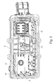
- the FIG. 1 shows in a schematic three-dimensional representation of a Wegdombautician 1 as an embodiment of the invention.
- the Heidelbergdombautician 1 is designed to implement a selector and / or switching movement, which is initiated by a user or an actuator, and forward to a downstream transmission, in particular a change-speed gearbox.
- the Heidelbergdombautician 1 is designed in particular for use in a motor vehicle.
- a lever mechanism 2 which has mechanical interfaces, for example in the form of ball heads 3 for mechanical coupling, for example, with Bowden cables or shift rails.
- the selection and / or switching movements are transmitted to a switching shaft 4, which in the FIG. 2 can be seen.
- the FIG. 2 shows the Heidelbergdombautician 1 from the bottom also in a schematic three-dimensional representation.
- the shift shaft 4 is in a Wegdomgephaseuse 5 or via the Heidelbergdomgephaseuse 5 slidably mounted with respect to their axial extent and.
- the Heidelbergdomgephaseuse 5 is formed of plastic and preferably produced by plastic injection molding.
- Kunststofferabitese 6 are attached to the switching shaft 4, which transmits the now implemented switching and / or selection movement on switching rails, not shown, or other elements.
- the shift rails extend perpendicular to the shift shaft 4, so that they are moved in a pivoting movement of the shift finger sections 6 about its own longitudinal axis in the longitudinal direction of the shift rails.
- the shift finger sections 6 can optionally act directly on the shift rails or via driver elements on the shift rails.
- each shift finger portion 6 a plurality of shift rails, for example, three shift rails assigned, which are selectively actuated depending on the axial position of the shift shaft 4 of the shift finger sections 6 and those - especially up to the reverse gear - two selectable gears, for example, first second gear or third fourth gear are assigned.
- the Heidelberggepiece 5 has two mutually spatially separated chamber areas 7 and 8, by or in which the switching shaft 4 extends.
- a gate assembly 9 is realized, which defines a forced or sliding guide of the shift shaft 4 with respect to the sliding and / or pivoting movements.
- a latching arrangement 10 is positioned, which converts a latching of the switching shaft 4 at certain positions, in particular at corresponding to a selected and / or engaged gear positions.
- the switching or selection force to be expended is controlled by the latching arrangement 10.
- the switching shaft 4 ends with a free, ungelagerten end 15th
- the switching shaft 4 is mounted on two bearing portions 11, 12, wherein the first bearing portion 11 in the region of a through hole 13 in the Heidelbergdomgetude 5 and the second bearing portion 12 in a gutter 14 between the first chamber portion 7 and the second chamber portion 8 is arranged.
- the selector shaft 4 is cantilevered with respect to the free end 15 in the region of the detent arrangement 10.
- FIG. 3 shows the one-piece Wegdomgeophuse 5 in an isometric schematic representation of the bottom.
- a detent 16 can be seen, which is in a holder 17, which forms a receptacle for the detent 16, is pressed.
- the lock 16 is in the FIG. 6 shown in a schematic three-dimensional drawing as a single module.
- the detent 16 includes a stationary sleeve-shaped portion 18 in which a probe element 19 is mounted, which holds a rotatably mounted ball 20 at the free end.
- the test element 19 is arranged in the stationary portion 18 as a movable portion longitudinally displaceable along the longitudinal extension of the detent 16 under bias, so that the probe element 19 is pushed out of or from the stationary portion 18.
- the lock 16 moves a latching plate 21 (FIG. FIG. 2 ), which is arranged at the free end 15 of the switching shaft 4 on the shift finger portion 6.
- the latching plate 21 has a three-dimensional contour, wherein the contour is selected so that in the interaction between latching plate 21 and locking 16 latching areas or areas arise with increased switching and / or selection resistor.
- the holder 17 is formed by a tower-like protruding from the switching dome housing 5 receiving body 22 which is integrally and / or einmaterialig connected to the Wegdomgephase 5.
- receiving body 22 For lateral support of the receiving body 22 are integrally formed on these support wings 23.
- the receiving body 22 or the holder 17 is formed like a blind hole, wherein the ceiling portion 24 of the receiving body 22 is formed in one piece and einmaterialig.
- An assembly of the holder 17 with the lock 16 can take place only starting from the interior of the Wegdomgekoruses 5,
- FIGS. 4 and 5 show, both of which show a schematic three-dimensional representation of the holder 17, starting from the interior of the Wegdomgeophuses 5, a plurality of clamping ribs 25 is integrally formed on the inner walls of the receiving body 22 so that the holder 17 is tapered in free diameter such that the lock 16th is held in the region of the stationary portion 18 by force and / or frictional engagement.
- the inside of the lid 24 may form an end stop for the detent 16; Alternatively, another end stop is provided in the receiving body 22.
- Endlwillungskanäle are provided between the clamping ribs 25, which extend analogously to the clamping ribs 25 in the longitudinal extension of the receiving body 22 and the detent 16 and ensure a venting of the holder 17 in the area under the lid 24 in the interior of the Wegdomgeophuses 5.
- a locking rail 26 is shown, which is arranged parallel to the longitudinal extension of the switching shaft 4 slidably.
- the task of the locking rail 26 is to selectively release one of the shift rails to be actuated and to lock the others in order to prevent an oblique shift.
- the locking rail 26 is in a single representation in a schematic three-dimensional representation in the FIG. 8 shown. From the synopsis of the Figures 2 and 8th Edge recesses 27 can be seen, which are facing away from the Wegdomgeophuse 5 introduced into the locking rail 26. These edge recesses 27 form the area through which one of the shift rails can move freely, wherein the surrounding areas 28 form a barrier for the non-actuated shift rails.
- the middle part 29 of the locking rail 26 is formed narrow perpendicular to the longitudinal extent, wherein the locking rail 26 is guided in a guide channel 30 in the switching dome housing 5 in the region of the central part 29.
- the guide channel 30 is integrally formed as a further receptacle in the Heidelbergdomgeophuse 5 and can be similar to the holder 17 during manufacture the Wegdomgeophuses, in particular in an injection molding process, are created in the context of the original molding process.
- guide ribs 31 are integrally formed on both sides, which ensure a low-tolerance guidance of the locking rail 26.
- the open side of the guide channel 30 is at least partially closed by a lid 32 which, for example, welded, glued or screwed. through the lid 32, an all-sided guidance of the locking rail 26 is implemented in the central part 29, so that it is held captive.
- FIG. 7 shows the lid 32, which in each case has shoulders 33 on the longitudinal sides, which improves a simple positioning in the guide channel 30.
- LIST OF REFERENCE NUMBERS 1 Heidelbergdombautechnik 32 cover 2 leverage 33 paragraphs 3 ball heads 4 shift shaft 5 gearshift tower 6
- Arre 17 bracket 18 sleeve-shaped section 19 scanning element 20
Description
Die Erfindung betrifft eine Kunststoffgetriebeabdeckung zur Abdeckung eines Schaltgetriebes für ein Fahrzeuges mit einem Gehäuseabschnitt, wobei der Gehäuseabschnitt einen Innenraum des Schaltgetriebes von einem Umgebungsraum trennt und wobei der Gehäuseabschnitt eine Aufnahme für eine Funktionseinheit des Schaltgetriebes bildet, welche zumindest abschnittsweise bei einem Wähl- und/oder Schaltvorgang des Schaltgetriebes bewegt wird. Die Erfindung betrifft auch eine Schaltdombaueinheit mit dieser Kunststoffgetriebeabdeckung.The invention relates to a plastic gear cover for covering a gearbox for a vehicle with a housing portion, wherein the housing portion separates an interior of the gearbox from an ambient space and wherein the housing portion forms a receptacle for a functional unit of the gearbox, which at least partially in a dial-up and / or Shifting the gearbox is moved. The invention also relates to a Schaltdombaueinheit with this plastic gear cover.
Bei Schaltgetrieben von Fahrzeugen ist oftmals ein Schaltdom vorgesehen, in dem eine Schaltwelle zur Übertragung von Schalt- und/oder Wählbewegungen gelagert ist. Ein derartiger Schaltdom weist üblicherweise eine Abdeckung auf, die den Getriebeinnenraum mit Ölsumpfatmosphäre von einem weitgehend ölfreien Umgebungsraum trennt.In manual transmissions of vehicles, a shift dome is often provided, in which a shift shaft is mounted for the transmission of switching and / or Wählbewegungen. Such a shift dome usually has a cover that separates the transmission interior with oil sump atmosphere of a largely oil-free environment space.
Beispielsweise offenbart die Offenlegungsschrift
Die Druckschrift
Der Erfindung liegt die Aufgabe zugrunde, eine Kunststoffgetriebeabdeckung sowie eine Schaltdombaueinheit mit einer derartigen Kunststoffgetriebeabdeckung vorzuschlagen, welche sich durch ein verbessertes Funktionsverhalten auszeichnen und die sich auf einfache Weise herstellen lassen.The invention has for its object to provide a plastic gear cover and a Schaltdombaueinheit with such a plastic gear cover, which are characterized by improved performance and can be produced in a simple manner.
Diese Aufgabe wird durch eine Kunststoffgetriebeabdeckung mit den Merkmalen des Anspruchs 1 sowie durch eine Schaltdombaueinheit mit den Merkmalen des Anspruchs 6 gelöst. Besondere Ausführungsarten der Erfindung sind den Unteransprüchen zu entnehmen.This object is achieved by a plastic gear cover with the features of claim 1 and by a Schaltdombaueinheit with the features of
Bevorzugte oder vorteilhafte Ausführungsformen der Erfindung ergeben sich aus der nachfolgenden Beschreibung sowie den beigefügten Figuren.Preferred or advantageous embodiments of the invention will become apparent from the following description and the accompanying drawings.
Im Rahmen der Erfindung wird eine Kunststoffgetriebeabdeckung zur Abdeckung eines Schaltgetriebes eines Fahrzeugs vorgeschlagen. Die Kunststoffgetriebeabdeckung ist aus einem vorzugsweise verstärkten, insbesondere glasfaserverstärkten Kunststoff, gefertigt und optional im Spritzgussverfahren hergestellt. Sie dient zur Abdeckung eines Schaltgetriebes, insbesondere eines Zahnräderwechselgetriebe für ein Fahrzeug.In the context of the invention, a plastic gear cover for covering a gearbox of a vehicle is proposed. The plastic gear cover is made of a preferably reinforced, in particular glass fiber reinforced plastic, manufactured and optionally by injection molding. It serves to cover a gearbox, in particular a change-speed gearbox for a vehicle.
Die Kunststoffgetriebeabdeckung weist einen Gehäuseabschnitt auf, wobei der Gehäuseabschnitt einen Innenraum des Schaltgetriebes von einem Umgebungsraum trennt. Unter einem Innenraum wird bevorzugt ein Raum mit Ölsumpfatmosphäre oder einer anderen Schmierstoffalmosphäre verstanden, welche kommunizierend mit einem Aufnahmeraum des Schaltgetriebes verbunden ist. Unter einem Umgebungsraum wird vorzugsweise ein Bereich verstanden, welcher außerhalb von der Ölsumpf- bzw. Schmierstoffatmosphäre angeordnet ist. Der Gehäuseabschnitt ist bevorzugt einstückig und/oder einmaterialig mit der Kunststoffgetriebeabdeckung verbunden und/oder aus Kunststoff gefertigt.The plastic gear cover has a housing section, wherein the housing section separates an interior of the gearbox from an ambient space. Under an interior is preferably understood a space with oil sump atmosphere or other lubricant atmosphere, which is communicatively connected to a receiving space of the gearbox. Under an environment space is preferably understood a region which is arranged outside of the oil sump or lubricant atmosphere. The housing portion is preferably integrally and / or material connected to the plastic gear cover and / or made of plastic.
Der Gehäuseabschnitt bildet eine Aufnahme, insbesondere eine Halterung, für eine Funktionseinheit des Schaltgetriebes, welche zumindest abschnittsweise, insbesondere teilweise, bei einem Wähl- und/oder Schaltvorgang des Schaltgetriebes bewegt wird. Die Bewegung der Funktionseinheit bzw. Teilen davon ist bevorzugt nicht-seriell in der kinematischen Kette zur Übertragung der Schaltund/oder Wählbewegung von einem Benutzer und/oder Aktor zu dem Schaltgetriebe ausgebildet. Bevorzugt erfolgt die Bewegung parallel bzw. mitgeführt zu der kinematischen Kette und/oder verbindet die kinematische Kette mit einem stationären Gestellglied.The housing portion forms a receptacle, in particular a holder, for a functional unit of the gearbox, which is at least partially, in particular partially, moved in a selection and / or switching operation of the gearbox. The movement of the functional unit or parts thereof is preferably formed non-serially in the kinematic chain for transmitting the switching and / or selecting movement of a user and / or actuator to the transmission. The movement preferably takes place parallel to or carried along to the kinematic chain and / or connects the kinematic chain to a stationary frame member.
Erfindungsgemäß wird offenbart, dass die Aufnahme einstückig, insbesondere einmaterialig, in dem Gehäuseabschnitt eingebracht ist. Bevorzugt ist die Aufnahme in den Gehäuseabschnitt, insbesondere durch einen Urformvorgang, eingeformt. Die Aufnahme öffnet sich ausschließlich zu dem bzw. in den Innenraum.According to the invention it is disclosed that the receptacle is integrally, in particular einmaterialig, introduced into the housing portion. Preferably, the receptacle in the housing portion, in particular by a primary molding process, formed. The recording opens exclusively to or into the interior.
Es ist dabei eine Überlegung der Erfindung, Durchgangsöffnungen durch den Gehäuseabschnitt zwischen Innenraum und Umgebungsraum weitgehend zu vermeiden. Derartige Durchgangsöffnungen stellen zum einen eine erhöhte Anforderung bei der Fertigung bzw. der Montage der Kunststoffgetriebeabdeckung dar, da diese zuverlässig abgedichtet werden müssen. Zum zweiten sind Durchgangsöffnungen stets eine mögliche Fehlerquelle für Leckagen. Im Rahmen der Erfindung wird deshalb vorgeschlagen, bei der Aufnahme für die Funktionseinheit derartige Durchgangsöffnungen nach außen zu vermeiden und die Aufnahme ausschließlich durch den Innenraum zugänglich zu machen. Der Vorteil der Erfindung liegt in einem verringerten Montageaufwand sowie aufgrund der fehlenden Fehlerquelle der Durchgangsöffnungen in einem verbesserten Funktionsverhalten der Kunststoffgetriebeabdeckung.It is a consideration of the invention to largely avoid passage openings through the housing portion between the interior and the surrounding space. On the one hand, such passage openings represent an increased requirement in the production or assembly of the plastic gear cover, since these must be reliably sealed. The second is Through holes always a possible source of error for leaks. In the context of the invention it is therefore proposed to avoid such passage openings to the outside in the recording for the functional unit and to make the recording exclusively accessible through the interior. The advantage of the invention lies in a reduced installation effort and due to the lack of error source of the through holes in an improved performance of the plastic gear cover.
Bei einer bevorzugten Ausführungsform der Erfindung umfasst die Kunststoffgetriebeabdeckung eine Arretierung, die insbesondere die Schalt- und/oder Wählkrafteinstellung der Schaltwelle arretiert, als die Funktionseinheit. Die Arretierung umfasst bevorzugt ein längsverschiebbares Tastelement, welches für ein Abfahren einer Rastkontur geeignet und/oder ausgebildet ist. Bei Wählund/oder Schaltvorgängen fährt das Tastelement der Arretierung die Rastkontur ab und wird dabei in Längsrichtung bewegt.In a preferred embodiment of the invention, the plastic gear cover comprises a lock, which locks in particular the shift and / or selection force setting of the shift shaft, as the functional unit. The lock preferably comprises a longitudinally displaceable probe element which is suitable and / or designed for driving off a latching contour. When Wählund / or switching operations, the probe element of the locking moves from the locking contour and is thereby moved in the longitudinal direction.
Bei einer bevorzugten Weiterbildung der Erfindung ist die Arretierung als eine Baugruppe realisiert, welche einen stationären Abschnitt und einen bewegbaren Abschnitt aufweist, wobei der stationäre Abschnitt stationär in der Aufnahme aufgenommen ist und der bewegbare Abschnitt in dem stationären Abschnitt gelagert und/oder geführt ist. Bei dieser Weiterbildung kann die Arretierung als Baugruppe mit einem geringen Montageaufwand in die Aufnahme eingesetzt, insbesondere eingepresst, werden.In a preferred embodiment of the invention, the locking is realized as an assembly having a stationary portion and a movable portion, wherein the stationary portion is received stationary in the receptacle and the movable portion is supported and / or guided in the stationary portion. In this development, the lock can be used as a module with a low installation effort in the recording, in particular pressed.
Bei einer konstruktiven Realisierung ist die Aufnahme sacklochartig ausgebildet, wobei der Ausgang des Sacklochs in den Innenraum gerichtet ist. Der Querschnitt senkrecht zur Tiefenerstreckung der sacklochartigen Aufnahme kann beliebig ausgebildet sein, beispielsweise oval, kreuzförmig, rund, elliptisch etc. In Tiefenerstreckung kann der Querschnitt der Aufnahme konstant oder im Wesentlichen konstant ausgebildet sein oder sich bevorzugt konvergierend verändern. Besonders bevorzugt bildet die Aufnahme eine hohlzylindrische und/oder konusförmige Halterung. Bei der Halterung ist es auch ausreichend, wenn das Funktionsteil über Halterungsbereiche oder - im Querschnitt senkrecht zur Tiefenerstreckung betrachtet - über Halterungspunkte bzw. - strecken berührend festgelegt ist.In a structural realization, the receptacle is formed like a blind hole, wherein the output of the blind hole is directed into the interior. The cross-section perpendicular to the depth extension of the blind-hole-like receptacle can be of any desired design, for example oval, cross-shaped, round, elliptical, etc. In depth extension, the cross-section of the receptacle can be constant or substantially constant or preferably converge. Particularly preferably, the receptacle forms a hollow cylindrical and / or cone-shaped holder. When the holder, it is also sufficient if the functional part on mounting areas or - in cross-section perpendicular considered to extend in depth - is touching on holding points or - distances fixed.
Insbesondere mit dem Ziel eines minimierten Materialaufwands ist es bevorzugt, wenn der Gehäuseabschnitt zur Bildung der Aufnahme in den Umgebungsraum gegenüber der Kunststoffgetriebeabdeckung auskragend ausgebildet ist. Beispielsweise ist der Gehäuseabschnitt turmartig auskragend realisiert, wobei optional kunststoffgerecht Verstärkungsrippen zwischen Gehäuseabschnitt und Kunststoffgetriebeabdeckung in dem Umgebungsraum vorgesehen sein können.In particular, with the aim of a minimized material cost, it is preferred if the housing section is designed to protrude into the surrounding space with respect to the plastic gear cover in order to form the receptacle. For example, the housing section is realized towering cantilevered, which may optionally be provided in accordance with the plastic reinforcement ribs between the housing section and plastic gear cover in the surrounding space.
Nach einer bevorzugten Weiterbildung der Erfindung sind an den Wänden der Aufnahme Mittel zur kraft- und/oder reibschlüssigen Festlegung der Funktionseinheit und/oder zur Entlüftung der Aufnahme, insbesondere des Sacklochgrundes angeordnet. Diese Weiterbildung unterstützt nochmals das erfinderische Streben, eine einfache Montage zu erlauben, indem die Funktionseinheit in die Aufnahme eingeführt, insbesondere eingepresst, wird, wobei aufnahmeseitige Mittel zur Festlegung der Funktionseinheit vorgesehen sind. Bevorzugt sind diese Mittel bereits bei der Fertigung, insbesondere im Urformvorgang, der Kunststoffgetriebeabdeckung integriert worden. Die Mittel zur Entlüftung der Aufnahme dienen dazu, einen Endraum, welcher möglicherweise durch den Einbau der Funktionseinheit ansonsten als totes Volumen von dem Innenraum abgeschlossen wäre, zu entlüften, so dass eine Vakuum- oder Überdruckbildung in diesem Endraum vermieden wird.According to a preferred embodiment of the invention, means for non-positive and / or frictional fixing of the functional unit and / or for venting the recording, in particular the blind hole bottom are arranged on the walls of the receptacle. This development further supports the inventive effort to allow a simple assembly by the functional unit introduced into the receptacle, in particular pressed, is, with receiving side means for fixing the functional unit are provided. Preferably, these means have already been integrated in the production, in particular in the original molding process, the plastic gear cover. The means for venting the receptacle serve to vent an end space, which would otherwise be completed by the installation of the functional unit otherwise as a dead volume of the interior, so that a vacuum or overpressure formation is avoided in this end space.
Bei einer möglichen konstruktiven Realisierung sind an den Innenwänden der Aufnahme Stege angeformt, welche in Tiefenerstreckung der Aufnahme verlaufen und die die Funktionseinheit kraft- und/oder reibschlüssig halten bzw. als die Mittel ausgebildet sind. Derartige Stege weisen den Vorteil auf, dass sie bei einem Einpressen der Funktionseinheit einfach deformierbar sind und auf diese Weise Fertigungstoleranzen ausgleichen können, wobei die Zwischenräume zwischen den Stegen zugleich als Mittel zur Entlüftung dienen.In a possible structural realization webs are formed on the inner walls of the recording, which extend in the depth extension of the receptacle and hold the functional unit non-positively and / or frictionally engaged or formed as the means. Such webs have the advantage that they are easily deformed during insertion of the functional unit and can compensate for manufacturing tolerances in this way, the spaces between the webs also serve as a means of ventilation.
Bei einer möglichen konstruktiven Realisierung der Weiterbildung kann eine Verriegelungsschiene zur Verriegelung von Schaltschienen ausgebildet sein. Eine derartige Verriegelungsschiene weist korrespondierend zu den Schaltschienen Randaussparungen auf, wobei je nach Position der Verriegelungsschiene Schaltschienen gesperrt oder verschiebbar sind.In a possible constructive realization of the development, a locking rail can be designed for locking shift rails. Such a locking rail has corresponding to the switching rails edge recesses, which are locked or displaceable depending on the position of the locking rail shift rails.
Ein Führungskanalkann die Verriegelungsschiene aufnehmen.A guide channel can receive the locking rail.
Aus fertigungstechnischen Gründen ist es nicht möglich, einen umlaufend geschlossenen Führungskanal durch einen Urformvorgang, beispielsweise durch einen Spritzgussvorgang, zu erzeugen. Um nun eine verliersichere Führung der Verriegelungsschiene zu gewährleisten, weist die Kunststoffgetriebeabdeckung bei eingelegter Verriegelungsschiene einen zusätzlichen Kunststoffdeckel auf, der als separates Bauteil gefertigt ist und den Führungskanal an einer offenen Seite gegenüber dem Innenraum zumindest abschnittsweise abschließt. Durch diesen Kunststoffdeckel wird die Verriegelungsschiene allseitig geführt und zugleich verliersicher gehalten. Es ist hierbei möglich, dass der Kunststoffdeckel geklipst, geschweißt, geklebt oder eingeschraubt wird.For manufacturing reasons, it is not possible to produce a circumferentially closed guide channel through a primary molding process, for example by an injection molding process. In order to ensure a captive leadership of the locking rail, the plastic gear cover with inserted locking rail on an additional plastic lid, which is made as a separate component and the guide channel terminates at least partially at an open side relative to the interior. Through this plastic lid, the locking bar is guided on all sides and at the same time held captive. It is possible that the plastic lid is clipped, welded, glued or screwed.
Zur Minimierung von Toleranzen bei der Führung der Verriegelungsschiene ist es bevorzugt, wenn an den Wänden des Führungskanals Führungsrippen angeformt sind. Die Führungsrippen erstrecken sich vorzugsweise senkrecht zu der Verschiebungsrichtung der Verriegelungsschiene.To minimize tolerances in the guidance of the locking rail, it is preferred if guide ribs are formed on the walls of the guide channel. The guide ribs preferably extend perpendicular to the direction of displacement of the locking rail.
Ein weiterer Gegenstand der Erfindung betrifft eine Schaltdombaueinheit für ein Schaltgetriebe eines Fahrzeugs mit einer Schaltwelle und einem Kunststoffschaltdomgehäuse. Die Schaltwelle ist in und/oder über das Kunststoffschaltdomgehäuse gelagert, wobei dieses als die zuvor beschriebene Kunststoffgetriebeabdeckung ausgebildet ist. Das Kunststoffschaltdomgehäuse kann als ein hochkomplexes, einstückiges Bauteil z.B. in einem Spritzgussverfahren gefertigt werden.Another object of the invention relates to a Schaltdombaueinheit for a manual transmission of a vehicle with a switching shaft and a Kunststoffschaltdomgehäuse. The shift shaft is mounted in and / or over the plastic shift dome housing, this being designed as the previously described plastic gear cover. The Kunststoffschaltdomgehäuse can be manufactured as a highly complex, one-piece component, for example in an injection molding process.
Bei einer bevorzugten Realisierung der Erfindung ist die Schaltwelle gegenüber einer Kopplungsöffnung des Kunststoffschaltdomgehäuses mit einem benachbarten Getriebegehäuse liegend angeordnet. Insbesondere bei dieser Realisierung ist die Verriegelungsschiene parallel zu der Schaltwelle ausgerichtet und wird von dieser mitgeführt und/oder die Arretierung ist in ihrer Längsrichtung senkrecht erstreckend zu der Schaltwelle positioniert.In a preferred embodiment of the invention, the switching shaft is arranged lying opposite a coupling opening of the Kunststoffschaltdomgehäuses with an adjacent transmission housing. In particular, in this implementation, the locking rail is aligned parallel to the shift shaft and is carried by this and / or the lock is positioned in its longitudinal direction extending perpendicular to the shift shaft.
Weitere Merkmale, Vorteile und Wirkungen der Erfindung ergeben sich aus der nachfolgenden Beschreibung eines bevorzugten Ausführungsbeispiels der Erfindung.Further features, advantages and effects of the invention will become apparent from the following description of a preferred embodiment of the invention.
Gleiche oder einander entsprechende Teile sind jeweils mit gleichen bzw. einander entsprechenden Bezugszeichen versehen. Es wird unterstrichen, dass die Einzelbaugruppen oder Einzelkomponenten auch in anderen Vorrichtungen einsetzbar sind.The same or corresponding parts are each provided with the same or corresponding reference numerals. It is emphasized that the individual modules or individual components can also be used in other devices.
Die
Die Wähl- und/oder Schaltbewegungen werden auf eine Schaltwelle 4 übertragen, welche in der
Die
Das Schaltdomgehäuse 5 weist zwei voneinander räumlich getrennte Kammerbereiche 7 und 8 auf, durch bzw. in die sich die Schaltwelle 4 erstreckt. In dem ersten Kammerbereich 7, durch den sich die Schaltwelle 4 vollständig oder durchgehend erstreckt, ist eine Kulissenanordnung 9 realisiert, die eine Zwangs- oder Kulissenführung der Schaltwelle 4 hinsichtlich der Verschiebeund/oder Schwenkbewegungen definiert. Im zweiten Kammerbereich 8 ist eine Rastanordnung 10 positioniert, welcher ein Einrasten der Schaltwelle 4 bei bestimmten Positionen, insbesondere bei zu einem gewählten und/oder eingelegten Gang korrespondierenden Positionen umsetzt. Zudem wird durch die Rastanordnung 10 die aufzuwendende Schalt- bzw. Wählkraft gesteuert. Im zweiten Kammerbereich 8 endet die Schaltwelle 4 mit einem freien, ungelagerten Ende 15.The
Die Schaltwelle 4 ist über zwei Lagerbereiche 11, 12 gelagert, wobei der erste Lagerbereich 11 im Bereich einer Durchgangsöffnung 13 in dem Schaltdomgehäuse 5 und der zweite Lagerbereich 12 in einem Zwischensteg 14 zwischen dem ersten Kammerbereich 7 und dem zweiten Kammerbereich 8 angeordnet ist. Durch diese Lageranordnung ist die Schaltwelle 4 im Hinblick auf das freie Ende 15 im Bereich der Rastanordnung 10 fliegend gelagert.The switching shaft 4 is mounted on two bearing portions 11, 12, wherein the first bearing portion 11 in the region of a through hole 13 in the
Die
Wie der
Wie sich aus den
Zurückkehrend zu der
Der Führungskanal 30 ist als eine weitere Aufnahme einstückig in das Schaltdomgehäuse 5 eingeformt und kann ähnlich wie die Halterung 17 bei der Fertigung des Schaltdomgehäuses, insbesondere bei einem Spritzgussverfahren, im Rahmen des Urformvorgangs geschaffen werden. An den Wänden des Führungskanals 30 sind beidseitig Führungsrippen 31 angeformt, welche eine toleranzarme Führung der Verriegelungsschiene 26 gewährleisten.The
Um ein Herausfallen der Verriegelungsschiene 26 aus dem Führungskanal 30 zu verhindern, ist die offene Seite des Führungskanals 30 zumindest abschnittsweise durch einen Deckel 32 verschlossen, welcher beispielsweise aufgeschweißt, aufgeklebt oder eingeschraubt werden kann. durch den Deckel 32 wird eine allseitige Führung der Verriegelungsschiene 26 im Mittelteil 29 umgesetzt, so dass diese verliersicher gehalten wird.In order to prevent falling out of the locking
Zu unterstreichen ist, dass weder durch den Führungskanal 30 noch durch die Halterung 17 Durchgangsöffnungen von dem Innenraum des Schaltdomgehäuses und somit dem Getrieberaum zu einem Umgebungsraum außerhalb der Ölsumpfatmosphäre geschaffen werden. Stattdessen sind diese beiden Aufnahmen 17, 30 ausschließlich nach innen in den Innenraum geöffnet.It should be emphasized that through the
Die
Claims (6)
- Plastic transmission cover (5) for covering a gear-shift transmission of a vehicle with a housing portion, the housing portion separating an inner space of the gear-shift transmission from a surrounding space, and the housing portion forming a receptacle (17) for a functional unit (16, 26) of the gear-shift transmission, which functional unit is moved at least partially during a selecting and/or shifting operation of the gear-shift transmission, the receptacle (17) being introduced in one piece into the housing portion and opening solely towards the inner space, and the functional unit being formed by a detent (16) for the detention of a gear-shift shaft (4), characterized in that a plurality of clamping ribs (25), which hold the detent (16) non-positively and/or frictionally, are integrally formed on the walls of the receptacle (17).
- Plastic transmission cover (5) according to Claim 1, characterized in that the detent (16) is formed as a subassembly, a movable portion (19) of the detent (16) being arranged in or on a stationary portion (18) of the detent (16).
- Plastic transmission cover (5) according to one of the preceding claims, characterized in that the receptacle (17) is formed in the manner of a blind hole and/or forms a hollow-cylindrical and/or conical holding device.
- Plastic transmission cover (5) according to one of the preceding claims, characterized in that, to form the receptacle (17), the housing portion is designed, in particular, to project in the manner of a tower into the surrounding space.
- Plastic transmission cover (5) according to one of the preceding claims, characterized in that the clamping ribs (25) are arranged for the purpose of ventilating the receptacle (17).
- Gear-shift tower unit (1) for a gear-shift transmission of a vehicle, with a gear-shift shaft (4) and with a plastic gear-shift tower housing, the gearshift shaft (4) being mounted in and/or above the plastic gear-shift tower housing, characterized in that the plastic gear-shift tower housing is designed as the plastic transmission cover (5) according to one of the preceding claims.
Applications Claiming Priority (2)
| Application Number | Priority Date | Filing Date | Title |
|---|---|---|---|
| DE200810061894 DE102008061894A1 (en) | 2008-12-11 | 2008-12-11 | Plastic gear cover and Schaltdombaueinheit with the plastic gear cover |
| PCT/EP2009/065946 WO2010066594A1 (en) | 2008-12-11 | 2009-11-27 | Plastic transmission cover, and gear-shift tower unit having the plastic transmission cover |
Publications (2)
| Publication Number | Publication Date |
|---|---|
| EP2376817A1 EP2376817A1 (en) | 2011-10-19 |
| EP2376817B1 true EP2376817B1 (en) | 2014-10-22 |
Family
ID=41626187
Family Applications (1)
| Application Number | Title | Priority Date | Filing Date |
|---|---|---|---|
| EP09760865.7A Not-in-force EP2376817B1 (en) | 2008-12-11 | 2009-11-27 | Plastic transmission cover, and gear-shift tower unit having the plastic transmission cover |
Country Status (3)
| Country | Link |
|---|---|
| EP (1) | EP2376817B1 (en) |
| DE (1) | DE102008061894A1 (en) |
| WO (1) | WO2010066594A1 (en) |
Cited By (1)
| Publication number | Priority date | Publication date | Assignee | Title |
|---|---|---|---|---|
| CN106151505A (en) * | 2015-04-27 | 2016-11-23 | 长城汽车股份有限公司 | For the gearshift of vehicle and have the vehicle of this gearshift |
Families Citing this family (7)
| Publication number | Priority date | Publication date | Assignee | Title |
|---|---|---|---|---|
| DE102010034283A1 (en) | 2010-08-13 | 2012-02-16 | Schaeffler Technologies Gmbh & Co. Kg | Motor car gear wheel change gear component, has shift element i.e. shift fork, for changing gear positions of gear box, and selector interlock mechanism generating switching forces and firmly connected with shift element |
| DE102011104864A1 (en) * | 2011-06-22 | 2012-12-27 | GM Global Technology Operations LLC (n. d. Gesetzen des Staates Delaware) | Actuation module for manual gearbox of motor vehicle, has switching shaft for switching of gears of manual gearbox, and holder with switching contour support |
| DE102012006927B4 (en) * | 2012-04-05 | 2024-02-01 | Sew-Eurodrive Gmbh & Co Kg | Gearbox with housing |
| EP2787250B1 (en) * | 2013-04-03 | 2017-08-30 | C.R.F. Società Consortile per Azioni | A gearbox for a motor vehicle |
| US9976543B2 (en) | 2014-05-05 | 2018-05-22 | Ford Global Technologies, Llc | Transmission for motor vehicle and method of pumping transmission fluid through the transmission |
| DE102015102979A1 (en) * | 2015-03-02 | 2016-09-08 | Koki Technik Transmission Systems Gmbh | Switch cover for a motor vehicle transmission |
| DE102017127897A1 (en) | 2017-11-27 | 2019-05-29 | Schaeffler Technologies AG & Co. KG | Crab |
Family Cites Families (10)
| Publication number | Priority date | Publication date | Assignee | Title |
|---|---|---|---|---|
| DE3606052A1 (en) * | 1986-02-25 | 1986-07-31 | Zikeli, Friedrich, Dipl.-Ing. (TH), 7300 Esslingen | Case parts and cover parts produced ready for installation from plastic moulding compositions for motor vehicle drive assemblies and combustion engines |
| DE3913269A1 (en) * | 1989-04-22 | 1990-10-31 | Ford Werke Ag | SWITCHING DEVICE FOR INTERCHANGEABLE GEARBOXES OF MOTOR VEHICLES |
| DE19948422B4 (en) | 1999-10-07 | 2008-11-27 | Schaeffler Kg | Switching device of a transmission |
| DE10064918B4 (en) | 2000-12-23 | 2009-08-27 | Schaeffler Kg | Transmission dome for a transmission, in particular manual transmission for motor vehicles |
| DE102005010001A1 (en) | 2004-05-06 | 2005-12-29 | Volkswagen Ag | Manual gear shift assembly, for a motor vehicle gearbox, has a plastics holder for the gear shift stick with an additional reverse gear shift release unit integrated into it during injection molding in a single stage |
| SE531713C2 (en) * | 2005-11-30 | 2009-07-14 | Kongsberg Automotive As | Cylinder with 6 fixed positions |
| ATE464498T1 (en) * | 2007-03-01 | 2010-04-15 | Fiat Ricerche | CONTROL SYSTEM OF A SERVO CIRCUIT FOR A DUAL CLUTCH TRANSMISSION OF A MOTOR VEHICLE |
| DE102008029266A1 (en) * | 2008-06-19 | 2009-12-24 | Schaeffler Kg | Schaltdomgehäuse and switching dome with the Schaltdomgehäuse |
| DE102008029262B4 (en) * | 2008-06-19 | 2020-03-26 | Schaeffler Technologies AG & Co. KG | Locking device for locking shift rails of a transmission |
| DE102008029264A1 (en) * | 2008-06-19 | 2009-12-24 | Schaeffler Kg | Assembly and transport safety arrangement for a switching mechanism of a transmission |
-
2008
- 2008-12-11 DE DE200810061894 patent/DE102008061894A1/en not_active Withdrawn
-
2009
- 2009-11-27 WO PCT/EP2009/065946 patent/WO2010066594A1/en active Application Filing
- 2009-11-27 EP EP09760865.7A patent/EP2376817B1/en not_active Not-in-force
Cited By (2)
| Publication number | Priority date | Publication date | Assignee | Title |
|---|---|---|---|---|
| CN106151505A (en) * | 2015-04-27 | 2016-11-23 | 长城汽车股份有限公司 | For the gearshift of vehicle and have the vehicle of this gearshift |
| CN106151505B (en) * | 2015-04-27 | 2018-03-06 | 长城汽车股份有限公司 | Gearshift for vehicle and the vehicle with the gearshift |
Also Published As
| Publication number | Publication date |
|---|---|
| EP2376817A1 (en) | 2011-10-19 |
| WO2010066594A1 (en) | 2010-06-17 |
| DE102008061894A1 (en) | 2010-06-17 |
Similar Documents
| Publication | Publication Date | Title |
|---|---|---|
| EP2376817B1 (en) | Plastic transmission cover, and gear-shift tower unit having the plastic transmission cover | |
| EP1715210A2 (en) | Blocking element | |
| EP2288826B1 (en) | Method for producing a shift finger arrangement | |
| DE102010028965A1 (en) | Modular actuator for vehicle transmissions | |
| DE102008029264A1 (en) | Assembly and transport safety arrangement for a switching mechanism of a transmission | |
| DE19927033A1 (en) | Double-acting actuator for adjustment devices | |
| DE102009047715A1 (en) | Monorail switching device | |
| DE102008029266A1 (en) | Schaltdomgehäuse and switching dome with the Schaltdomgehäuse | |
| DE10012382B4 (en) | Manual shift lever for a vehicle change gearbox | |
| DE19913835C2 (en) | Switching device for motor vehicles | |
| EP2376799B1 (en) | Gearshift dome unit and method of fixing a bearing arrangement in a gearshift dome unit | |
| DE102005053867A1 (en) | Motor vehicle-transmission device, has transmission actuator with electric motor, where motor or central control shaft of actuator is arranged on side of section, on which central longitudinal axis of respective shafts are situated | |
| DE102009044411A1 (en) | Plug combination structure of a shift knob of an automatic transmission | |
| DE102009007904B4 (en) | manual shift | |
| EP2023020B1 (en) | Gearbox with switching support and outage protection | |
| EP1703175B1 (en) | Gear lever with a switch for controlling of at least a device of a vehicle | |
| DE10029620B4 (en) | Shifting shaft for a manual transmission and method for its production | |
| DE102006055181A1 (en) | Manual transmission for selecting and switching gears of motor vehicle, has internal circuit with blockable locking device for haptic feedback to hand lever, where basic position of lever is synchronized with n-position of circuit | |
| WO2014059981A1 (en) | Shifting device of a motor vehicle change-speed gearbox | |
| EP1281895B1 (en) | Shift lock mechanism | |
| DE102007008960B4 (en) | actuator | |
| DE102007052771A1 (en) | Device for joining cable pulls together comprises a locking unit which can be moved from an inactive position into an active position using a switching unit | |
| DE10325366B4 (en) | switching arrangement | |
| EP1602863A1 (en) | Device for interlocking and unlocking of the shift rods of a manual transmission | |
| DE19941795C1 (en) | Automobile automatic transmission gear selection knob has cog wheel cooperating with cog rack of gear selection push-button and cog rack of operating rod for automatic transmission |
Legal Events
| Date | Code | Title | Description |
|---|---|---|---|
| PUAI | Public reference made under article 153(3) epc to a published international application that has entered the european phase |
Free format text: ORIGINAL CODE: 0009012 |
|
| 17P | Request for examination filed |
Effective date: 20110711 |
|
| AK | Designated contracting states |
Kind code of ref document: A1 Designated state(s): AT BE BG CH CY CZ DE DK EE ES FI FR GB GR HR HU IE IS IT LI LT LU LV MC MK MT NL NO PL PT RO SE SI SK SM TR |
|
| RAP1 | Party data changed (applicant data changed or rights of an application transferred) |
Owner name: SCHAEFFLER TECHNOLOGIES AG & CO. KG |
|
| DAX | Request for extension of the european patent (deleted) | ||
| 17Q | First examination report despatched |
Effective date: 20130725 |
|
| RAP1 | Party data changed (applicant data changed or rights of an application transferred) |
Owner name: SCHAEFFLER TECHNOLOGIES GMBH & CO. KG |
|
| RIC1 | Information provided on ipc code assigned before grant |
Ipc: F16H 57/027 20120101ALN20140224BHEP Ipc: F16H 63/30 20060101ALN20140224BHEP Ipc: F16H 63/20 20060101AFI20140224BHEP Ipc: F16H 63/38 20060101ALN20140224BHEP |
|
| GRAJ | Information related to disapproval of communication of intention to grant by the applicant or resumption of examination proceedings by the epo deleted |
Free format text: ORIGINAL CODE: EPIDOSDIGR1 |
|
| GRAP | Despatch of communication of intention to grant a patent |
Free format text: ORIGINAL CODE: EPIDOSNIGR1 |
|
| INTG | Intention to grant announced |
Effective date: 20140403 |
|
| INTC | Intention to grant announced (deleted) | ||
| GRAP | Despatch of communication of intention to grant a patent |
Free format text: ORIGINAL CODE: EPIDOSNIGR1 |
|
| INTG | Intention to grant announced |
Effective date: 20140626 |
|
| GRAS | Grant fee paid |
Free format text: ORIGINAL CODE: EPIDOSNIGR3 |
|
| GRAA | (expected) grant |
Free format text: ORIGINAL CODE: 0009210 |
|
| AK | Designated contracting states |
Kind code of ref document: B1 Designated state(s): AT BE BG CH CY CZ DE DK EE ES FI FR GB GR HR HU IE IS IT LI LT LU LV MC MK MT NL NO PL PT RO SE SI SK SM TR |
|
| REG | Reference to a national code |
Ref country code: GB Ref legal event code: FG4D Free format text: NOT ENGLISH |
|
| REG | Reference to a national code |
Ref country code: CH Ref legal event code: EP |
|
| REG | Reference to a national code |
Ref country code: AT Ref legal event code: REF Ref document number: 692815 Country of ref document: AT Kind code of ref document: T Effective date: 20141115 |
|
| REG | Reference to a national code |
Ref country code: IE Ref legal event code: FG4D Free format text: LANGUAGE OF EP DOCUMENT: GERMAN |
|
| REG | Reference to a national code |
Ref country code: DE Ref legal event code: R096 Ref document number: 502009010130 Country of ref document: DE Effective date: 20141204 |
|
| RAP2 | Party data changed (patent owner data changed or rights of a patent transferred) |
Owner name: SCHAEFFLER TECHNOLOGIES AG & CO. KG |
|
| REG | Reference to a national code |
Ref country code: DE Ref legal event code: R081 Ref document number: 502009010130 Country of ref document: DE Owner name: SCHAEFFLER TECHNOLOGIES AG & CO. KG, DE Free format text: FORMER OWNER: SCHAEFFLER TECHNOLOGIES GMBH & CO. KG, 91074 HERZOGENAURACH, DE Effective date: 20150122 |
|
| REG | Reference to a national code |
Ref country code: NL Ref legal event code: VDEP Effective date: 20141022 |
|
| REG | Reference to a national code |
Ref country code: LT Ref legal event code: MG4D |
|
| PG25 | Lapsed in a contracting state [announced via postgrant information from national office to epo] |
Ref country code: ES Free format text: LAPSE BECAUSE OF FAILURE TO SUBMIT A TRANSLATION OF THE DESCRIPTION OR TO PAY THE FEE WITHIN THE PRESCRIBED TIME-LIMIT Effective date: 20141022 Ref country code: NO Free format text: LAPSE BECAUSE OF FAILURE TO SUBMIT A TRANSLATION OF THE DESCRIPTION OR TO PAY THE FEE WITHIN THE PRESCRIBED TIME-LIMIT Effective date: 20150122 Ref country code: LT Free format text: LAPSE BECAUSE OF FAILURE TO SUBMIT A TRANSLATION OF THE DESCRIPTION OR TO PAY THE FEE WITHIN THE PRESCRIBED TIME-LIMIT Effective date: 20141022 Ref country code: FI Free format text: LAPSE BECAUSE OF FAILURE TO SUBMIT A TRANSLATION OF THE DESCRIPTION OR TO PAY THE FEE WITHIN THE PRESCRIBED TIME-LIMIT Effective date: 20141022 Ref country code: IS Free format text: LAPSE BECAUSE OF FAILURE TO SUBMIT A TRANSLATION OF THE DESCRIPTION OR TO PAY THE FEE WITHIN THE PRESCRIBED TIME-LIMIT Effective date: 20150222 Ref country code: NL Free format text: LAPSE BECAUSE OF FAILURE TO SUBMIT A TRANSLATION OF THE DESCRIPTION OR TO PAY THE FEE WITHIN THE PRESCRIBED TIME-LIMIT Effective date: 20141022 Ref country code: PT Free format text: LAPSE BECAUSE OF FAILURE TO SUBMIT A TRANSLATION OF THE DESCRIPTION OR TO PAY THE FEE WITHIN THE PRESCRIBED TIME-LIMIT Effective date: 20150223 |
|
| PG25 | Lapsed in a contracting state [announced via postgrant information from national office to epo] |
Ref country code: GR Free format text: LAPSE BECAUSE OF FAILURE TO SUBMIT A TRANSLATION OF THE DESCRIPTION OR TO PAY THE FEE WITHIN THE PRESCRIBED TIME-LIMIT Effective date: 20150123 Ref country code: CY Free format text: LAPSE BECAUSE OF FAILURE TO SUBMIT A TRANSLATION OF THE DESCRIPTION OR TO PAY THE FEE WITHIN THE PRESCRIBED TIME-LIMIT Effective date: 20141022 Ref country code: LV Free format text: LAPSE BECAUSE OF FAILURE TO SUBMIT A TRANSLATION OF THE DESCRIPTION OR TO PAY THE FEE WITHIN THE PRESCRIBED TIME-LIMIT Effective date: 20141022 Ref country code: HR Free format text: LAPSE BECAUSE OF FAILURE TO SUBMIT A TRANSLATION OF THE DESCRIPTION OR TO PAY THE FEE WITHIN THE PRESCRIBED TIME-LIMIT Effective date: 20141022 Ref country code: PL Free format text: LAPSE BECAUSE OF FAILURE TO SUBMIT A TRANSLATION OF THE DESCRIPTION OR TO PAY THE FEE WITHIN THE PRESCRIBED TIME-LIMIT Effective date: 20141022 Ref country code: SE Free format text: LAPSE BECAUSE OF FAILURE TO SUBMIT A TRANSLATION OF THE DESCRIPTION OR TO PAY THE FEE WITHIN THE PRESCRIBED TIME-LIMIT Effective date: 20141022 |
|
| PG25 | Lapsed in a contracting state [announced via postgrant information from national office to epo] |
Ref country code: BE Free format text: LAPSE BECAUSE OF NON-PAYMENT OF DUE FEES Effective date: 20141130 |
|
| REG | Reference to a national code |
Ref country code: CH Ref legal event code: PL |
|
| REG | Reference to a national code |
Ref country code: DE Ref legal event code: R097 Ref document number: 502009010130 Country of ref document: DE |
|
| PG25 | Lapsed in a contracting state [announced via postgrant information from national office to epo] |
Ref country code: LI Free format text: LAPSE BECAUSE OF NON-PAYMENT OF DUE FEES Effective date: 20141130 Ref country code: CZ Free format text: LAPSE BECAUSE OF FAILURE TO SUBMIT A TRANSLATION OF THE DESCRIPTION OR TO PAY THE FEE WITHIN THE PRESCRIBED TIME-LIMIT Effective date: 20141022 Ref country code: EE Free format text: LAPSE BECAUSE OF FAILURE TO SUBMIT A TRANSLATION OF THE DESCRIPTION OR TO PAY THE FEE WITHIN THE PRESCRIBED TIME-LIMIT Effective date: 20141022 Ref country code: DK Free format text: LAPSE BECAUSE OF FAILURE TO SUBMIT A TRANSLATION OF THE DESCRIPTION OR TO PAY THE FEE WITHIN THE PRESCRIBED TIME-LIMIT Effective date: 20141022 Ref country code: SK Free format text: LAPSE BECAUSE OF FAILURE TO SUBMIT A TRANSLATION OF THE DESCRIPTION OR TO PAY THE FEE WITHIN THE PRESCRIBED TIME-LIMIT Effective date: 20141022 Ref country code: RO Free format text: LAPSE BECAUSE OF FAILURE TO SUBMIT A TRANSLATION OF THE DESCRIPTION OR TO PAY THE FEE WITHIN THE PRESCRIBED TIME-LIMIT Effective date: 20141022 Ref country code: MC Free format text: LAPSE BECAUSE OF FAILURE TO SUBMIT A TRANSLATION OF THE DESCRIPTION OR TO PAY THE FEE WITHIN THE PRESCRIBED TIME-LIMIT Effective date: 20141022 Ref country code: CH Free format text: LAPSE BECAUSE OF NON-PAYMENT OF DUE FEES Effective date: 20141130 |
|
| REG | Reference to a national code |
Ref country code: IE Ref legal event code: MM4A |
|
| PLBE | No opposition filed within time limit |
Free format text: ORIGINAL CODE: 0009261 |
|
| REG | Reference to a national code |
Ref country code: FR Ref legal event code: ST Effective date: 20150731 |
|
| STAA | Information on the status of an ep patent application or granted ep patent |
Free format text: STATUS: NO OPPOSITION FILED WITHIN TIME LIMIT |
|
| PG25 | Lapsed in a contracting state [announced via postgrant information from national office to epo] |
Ref country code: IT Free format text: LAPSE BECAUSE OF FAILURE TO SUBMIT A TRANSLATION OF THE DESCRIPTION OR TO PAY THE FEE WITHIN THE PRESCRIBED TIME-LIMIT Effective date: 20141022 |
|
| GBPC | Gb: european patent ceased through non-payment of renewal fee |
Effective date: 20150122 |
|
| 26N | No opposition filed |
Effective date: 20150723 |
|
| PG25 | Lapsed in a contracting state [announced via postgrant information from national office to epo] |
Ref country code: GB Free format text: LAPSE BECAUSE OF NON-PAYMENT OF DUE FEES Effective date: 20150122 Ref country code: IE Free format text: LAPSE BECAUSE OF NON-PAYMENT OF DUE FEES Effective date: 20141127 |
|
| PG25 | Lapsed in a contracting state [announced via postgrant information from national office to epo] |
Ref country code: FR Free format text: LAPSE BECAUSE OF NON-PAYMENT OF DUE FEES Effective date: 20141222 |
|
| REG | Reference to a national code |
Ref country code: AT Ref legal event code: MM01 Ref document number: 692815 Country of ref document: AT Kind code of ref document: T Effective date: 20141127 |
|
| PG25 | Lapsed in a contracting state [announced via postgrant information from national office to epo] |
Ref country code: SI Free format text: LAPSE BECAUSE OF FAILURE TO SUBMIT A TRANSLATION OF THE DESCRIPTION OR TO PAY THE FEE WITHIN THE PRESCRIBED TIME-LIMIT Effective date: 20141022 Ref country code: AT Free format text: LAPSE BECAUSE OF NON-PAYMENT OF DUE FEES Effective date: 20141127 |
|
| PG25 | Lapsed in a contracting state [announced via postgrant information from national office to epo] |
Ref country code: SM Free format text: LAPSE BECAUSE OF FAILURE TO SUBMIT A TRANSLATION OF THE DESCRIPTION OR TO PAY THE FEE WITHIN THE PRESCRIBED TIME-LIMIT Effective date: 20141022 |
|
| PG25 | Lapsed in a contracting state [announced via postgrant information from national office to epo] |
Ref country code: BG Free format text: LAPSE BECAUSE OF FAILURE TO SUBMIT A TRANSLATION OF THE DESCRIPTION OR TO PAY THE FEE WITHIN THE PRESCRIBED TIME-LIMIT Effective date: 20141022 |
|
| PG25 | Lapsed in a contracting state [announced via postgrant information from national office to epo] |
Ref country code: LU Free format text: LAPSE BECAUSE OF NON-PAYMENT OF DUE FEES Effective date: 20141127 Ref country code: MT Free format text: LAPSE BECAUSE OF FAILURE TO SUBMIT A TRANSLATION OF THE DESCRIPTION OR TO PAY THE FEE WITHIN THE PRESCRIBED TIME-LIMIT Effective date: 20141022 Ref country code: TR Free format text: LAPSE BECAUSE OF FAILURE TO SUBMIT A TRANSLATION OF THE DESCRIPTION OR TO PAY THE FEE WITHIN THE PRESCRIBED TIME-LIMIT Effective date: 20141022 Ref country code: HU Free format text: LAPSE BECAUSE OF FAILURE TO SUBMIT A TRANSLATION OF THE DESCRIPTION OR TO PAY THE FEE WITHIN THE PRESCRIBED TIME-LIMIT; INVALID AB INITIO Effective date: 20091127 |
|
| PG25 | Lapsed in a contracting state [announced via postgrant information from national office to epo] |
Ref country code: MK Free format text: LAPSE BECAUSE OF FAILURE TO SUBMIT A TRANSLATION OF THE DESCRIPTION OR TO PAY THE FEE WITHIN THE PRESCRIBED TIME-LIMIT Effective date: 20141022 |
|
| PGFP | Annual fee paid to national office [announced via postgrant information from national office to epo] |
Ref country code: DE Payment date: 20200130 Year of fee payment: 11 |
|
| REG | Reference to a national code |
Ref country code: DE Ref legal event code: R119 Ref document number: 502009010130 Country of ref document: DE |
|
| PG25 | Lapsed in a contracting state [announced via postgrant information from national office to epo] |
Ref country code: DE Free format text: LAPSE BECAUSE OF NON-PAYMENT OF DUE FEES Effective date: 20210601 |
|
| P01 | Opt-out of the competence of the unified patent court (upc) registered |
Effective date: 20230522 |