EP2376817B1 - Couvercle de changement de vitesse en matière plastique et module de dôme de changement de vitesse avec le couvercle de changement de vitesse en matière plastique - Google Patents
Couvercle de changement de vitesse en matière plastique et module de dôme de changement de vitesse avec le couvercle de changement de vitesse en matière plastique Download PDFInfo
- Publication number
- EP2376817B1 EP2376817B1 EP09760865.7A EP09760865A EP2376817B1 EP 2376817 B1 EP2376817 B1 EP 2376817B1 EP 09760865 A EP09760865 A EP 09760865A EP 2376817 B1 EP2376817 B1 EP 2376817B1
- Authority
- EP
- European Patent Office
- Prior art keywords
- shift
- gear
- plastic
- receptacle
- transmission cover
- Prior art date
- Legal status (The legal status is an assumption and is not a legal conclusion. Google has not performed a legal analysis and makes no representation as to the accuracy of the status listed.)
- Not-in-force
Links
Images


Classifications
-
- F—MECHANICAL ENGINEERING; LIGHTING; HEATING; WEAPONS; BLASTING
- F16—ENGINEERING ELEMENTS AND UNITS; GENERAL MEASURES FOR PRODUCING AND MAINTAINING EFFECTIVE FUNCTIONING OF MACHINES OR INSTALLATIONS; THERMAL INSULATION IN GENERAL
- F16H—GEARING
- F16H63/00—Control outputs from the control unit to change-speed- or reversing-gearings for conveying rotary motion or to other devices than the final output mechanism
- F16H63/02—Final output mechanisms therefor; Actuating means for the final output mechanisms
- F16H63/08—Multiple final output mechanisms being moved by a single common final actuating mechanism
- F16H63/20—Multiple final output mechanisms being moved by a single common final actuating mechanism with preselection and subsequent movement of each final output mechanism by movement of the final actuating mechanism in two different ways, e.g. guided by a shift gate
-
- F—MECHANICAL ENGINEERING; LIGHTING; HEATING; WEAPONS; BLASTING
- F16—ENGINEERING ELEMENTS AND UNITS; GENERAL MEASURES FOR PRODUCING AND MAINTAINING EFFECTIVE FUNCTIONING OF MACHINES OR INSTALLATIONS; THERMAL INSULATION IN GENERAL
- F16H—GEARING
- F16H63/00—Control outputs from the control unit to change-speed- or reversing-gearings for conveying rotary motion or to other devices than the final output mechanism
- F16H63/02—Final output mechanisms therefor; Actuating means for the final output mechanisms
- F16H63/30—Constructional features of the final output mechanisms
- F16H63/38—Detents
-
- F—MECHANICAL ENGINEERING; LIGHTING; HEATING; WEAPONS; BLASTING
- F16—ENGINEERING ELEMENTS AND UNITS; GENERAL MEASURES FOR PRODUCING AND MAINTAINING EFFECTIVE FUNCTIONING OF MACHINES OR INSTALLATIONS; THERMAL INSULATION IN GENERAL
- F16H—GEARING
- F16H63/00—Control outputs from the control unit to change-speed- or reversing-gearings for conveying rotary motion or to other devices than the final output mechanism
- F16H2063/005—Preassembled gear shift units for mounting on gear case
-
- F—MECHANICAL ENGINEERING; LIGHTING; HEATING; WEAPONS; BLASTING
- F16—ENGINEERING ELEMENTS AND UNITS; GENERAL MEASURES FOR PRODUCING AND MAINTAINING EFFECTIVE FUNCTIONING OF MACHINES OR INSTALLATIONS; THERMAL INSULATION IN GENERAL
- F16H—GEARING
- F16H63/00—Control outputs from the control unit to change-speed- or reversing-gearings for conveying rotary motion or to other devices than the final output mechanism
- F16H63/02—Final output mechanisms therefor; Actuating means for the final output mechanisms
- F16H63/08—Multiple final output mechanisms being moved by a single common final actuating mechanism
- F16H63/20—Multiple final output mechanisms being moved by a single common final actuating mechanism with preselection and subsequent movement of each final output mechanism by movement of the final actuating mechanism in two different ways, e.g. guided by a shift gate
- F16H2063/202—Multiple final output mechanisms being moved by a single common final actuating mechanism with preselection and subsequent movement of each final output mechanism by movement of the final actuating mechanism in two different ways, e.g. guided by a shift gate using cam plates for selection or shifting, e.g. shift plates with recesses or groves moved by a selector extension
-
- F—MECHANICAL ENGINEERING; LIGHTING; HEATING; WEAPONS; BLASTING
- F16—ENGINEERING ELEMENTS AND UNITS; GENERAL MEASURES FOR PRODUCING AND MAINTAINING EFFECTIVE FUNCTIONING OF MACHINES OR INSTALLATIONS; THERMAL INSULATION IN GENERAL
- F16H—GEARING
- F16H63/00—Control outputs from the control unit to change-speed- or reversing-gearings for conveying rotary motion or to other devices than the final output mechanism
- F16H63/02—Final output mechanisms therefor; Actuating means for the final output mechanisms
- F16H63/30—Constructional features of the final output mechanisms
- F16H2063/3076—Selector shaft assembly, e.g. supporting, assembly or manufacturing of selector or shift shafts; Special details thereof
-
- F—MECHANICAL ENGINEERING; LIGHTING; HEATING; WEAPONS; BLASTING
- F16—ENGINEERING ELEMENTS AND UNITS; GENERAL MEASURES FOR PRODUCING AND MAINTAINING EFFECTIVE FUNCTIONING OF MACHINES OR INSTALLATIONS; THERMAL INSULATION IN GENERAL
- F16H—GEARING
- F16H57/00—General details of gearing
- F16H57/02—Gearboxes; Mounting gearing therein
- F16H57/027—Gearboxes; Mounting gearing therein characterised by means for venting gearboxes, e.g. air breathers
Definitions
- the invention relates to a plastic gear cover for covering a gearbox for a vehicle with a housing portion, wherein the housing portion separates an interior of the gearbox from an ambient space and wherein the housing portion forms a receptacle for a functional unit of the gearbox, which at least partially in a dial-up and / or Shifting the gearbox is moved.
- the invention also relates to a Heidelbergdombauisme with this plastic gear cover.
- a shift dome In manual transmissions of vehicles, a shift dome is often provided, in which a shift shaft is mounted for the transmission of switching and / or Wählmonyen. Such a shift dome usually has a cover that separates the transmission interior with oil sump atmosphere of a largely oil-free environment space.
- the published patent application DE 199 48 422 A1 a switching device of a transmission with at least one longitudinally displaceable and / or pivotally mounted in a housing transmission shaft for transmitting selection and / or switching movements.
- the switching device has a cover with a latching contour, wherein cooperating with the latching contour arranged on the transmission shaft latching element.
- the cover for example, receptacles for a storage of the transmission shaft are arranged.
- the publication DE 100 649 18 A1 discloses a similar shift dome for a transmission, wherein the shift dome housing is substantially pot-shaped and is closed by means of a lid which rests on the shift dome housing. According to the description, the lid can also be made as a plastic part.
- the invention has for its object to provide a plastic gear cover and a Heidelbergbauech with such a plastic gear cover, which are characterized by improved performance and can be produced in a simple manner.
- a plastic gear cover for covering a gearbox of a vehicle.
- the plastic gear cover is made of a preferably reinforced, in particular glass fiber reinforced plastic, manufactured and optionally by injection molding. It serves to cover a gearbox, in particular a change-speed gearbox for a vehicle.
- the plastic gear cover has a housing section, wherein the housing section separates an interior of the gearbox from an ambient space.
- an interior is preferably understood a space with oil sump atmosphere or other lubricant atmosphere, which is communicatively connected to a receiving space of the gearbox.
- Under an environment space is preferably understood a region which is arranged outside of the oil sump or lubricant atmosphere.
- the housing portion is preferably integrally and / or material connected to the plastic gear cover and / or made of plastic.
- the housing portion forms a receptacle, in particular a holder, for a functional unit of the gearbox, which is at least partially, in particular partially, moved in a selection and / or switching operation of the gearbox.
- the movement of the functional unit or parts thereof is preferably formed non-serially in the kinematic chain for transmitting the switching and / or selecting movement of a user and / or actuator to the transmission.
- the movement preferably takes place parallel to or carried along to the kinematic chain and / or connects the kinematic chain to a stationary frame member.
- the receptacle is integrally, in particular einmaterialig, introduced into the housing portion.
- the receptacle in the housing portion in particular by a primary molding process, formed.
- the recording opens exclusively to or into the interior.
- the plastic gear cover comprises a lock, which locks in particular the shift and / or selection force setting of the shift shaft, as the functional unit.
- the lock preferably comprises a longitudinally displaceable probe element which is suitable and / or designed for driving off a latching contour. When Wählund / or switching operations, the probe element of the locking moves from the locking contour and is thereby moved in the longitudinal direction.
- the locking is realized as an assembly having a stationary portion and a movable portion, wherein the stationary portion is received stationary in the receptacle and the movable portion is supported and / or guided in the stationary portion.
- the lock can be used as a module with a low installation effort in the recording, in particular pressed.
- the receptacle is formed like a blind hole, wherein the output of the blind hole is directed into the interior.
- the cross-section perpendicular to the depth extension of the blind-hole-like receptacle can be of any desired design, for example oval, cross-shaped, round, elliptical, etc.
- the cross-section of the receptacle can be constant or substantially constant or preferably converge.
- the receptacle forms a hollow cylindrical and / or cone-shaped holder. When the holder, it is also sufficient if the functional part on mounting areas or - in cross-section perpendicular considered to extend in depth - is touching on holding points or - distances fixed.
- the housing section is designed to protrude into the surrounding space with respect to the plastic gear cover in order to form the receptacle.
- the housing section is realized towering cantilevered, which may optionally be provided in accordance with the plastic reinforcement ribs between the housing section and plastic gear cover in the surrounding space.
- means for non-positive and / or frictional fixing of the functional unit and / or for venting the recording, in particular the blind hole bottom are arranged on the walls of the receptacle.
- This development further supports the inventive effort to allow a simple assembly by the functional unit introduced into the receptacle, in particular pressed, is, with receiving side means for fixing the functional unit are provided.
- these means have already been integrated in the production, in particular in the original molding process, the plastic gear cover.
- the means for venting the receptacle serve to vent an end space, which would otherwise be completed by the installation of the functional unit otherwise as a dead volume of the interior, so that a vacuum or overpressure formation is avoided in this end space.
- webs are formed on the inner walls of the recording, which extend in the depth extension of the receptacle and hold the functional unit non-positively and / or frictionally engaged or formed as the means.
- Such webs have the advantage that they are easily deformed during insertion of the functional unit and can compensate for manufacturing tolerances in this way, the spaces between the webs also serve as a means of ventilation.
- a locking rail can be designed for locking shift rails.
- Such a locking rail has corresponding to the switching rails edge recesses, which are locked or displaceable depending on the position of the locking rail shift rails.
- a guide channel can receive the locking rail.
- the plastic gear cover with inserted locking rail on an additional plastic lid which is made as a separate component and the guide channel terminates at least partially at an open side relative to the interior.
- the locking bar is guided on all sides and at the same time held captive. It is possible that the plastic lid is clipped, welded, glued or screwed.
- guide ribs are formed on the walls of the guide channel.
- the guide ribs preferably extend perpendicular to the direction of displacement of the locking rail.
- Another object of the invention relates to a Heidelbergdombautician for a manual transmission of a vehicle with a switching shaft and a Kunststoffschaltdomgeophuse.
- the shift shaft is mounted in and / or over the plastic shift dome housing, this being designed as the previously described plastic gear cover.
- the Kunststoffschaltdomgeophuse can be manufactured as a highly complex, one-piece component, for example in an injection molding process.
- the switching shaft is arranged lying opposite a coupling opening of the Kunststoffschaltdomgeophuses with an adjacent transmission housing.
- the locking rail is aligned parallel to the shift shaft and is carried by this and / or the lock is positioned in its longitudinal direction extending perpendicular to the shift shaft.
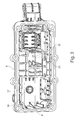
- the FIG. 1 shows in a schematic three-dimensional representation of a Wegdombautician 1 as an embodiment of the invention.
- the Heidelbergdombautician 1 is designed to implement a selector and / or switching movement, which is initiated by a user or an actuator, and forward to a downstream transmission, in particular a change-speed gearbox.
- the Heidelbergdombautician 1 is designed in particular for use in a motor vehicle.
- a lever mechanism 2 which has mechanical interfaces, for example in the form of ball heads 3 for mechanical coupling, for example, with Bowden cables or shift rails.
- the selection and / or switching movements are transmitted to a switching shaft 4, which in the FIG. 2 can be seen.
- the FIG. 2 shows the Heidelbergdombautician 1 from the bottom also in a schematic three-dimensional representation.
- the shift shaft 4 is in a Wegdomgephaseuse 5 or via the Heidelbergdomgephaseuse 5 slidably mounted with respect to their axial extent and.
- the Heidelbergdomgephaseuse 5 is formed of plastic and preferably produced by plastic injection molding.
- Kunststofferabitese 6 are attached to the switching shaft 4, which transmits the now implemented switching and / or selection movement on switching rails, not shown, or other elements.
- the shift rails extend perpendicular to the shift shaft 4, so that they are moved in a pivoting movement of the shift finger sections 6 about its own longitudinal axis in the longitudinal direction of the shift rails.
- the shift finger sections 6 can optionally act directly on the shift rails or via driver elements on the shift rails.
- each shift finger portion 6 a plurality of shift rails, for example, three shift rails assigned, which are selectively actuated depending on the axial position of the shift shaft 4 of the shift finger sections 6 and those - especially up to the reverse gear - two selectable gears, for example, first second gear or third fourth gear are assigned.
- the Heidelberggepiece 5 has two mutually spatially separated chamber areas 7 and 8, by or in which the switching shaft 4 extends.
- a gate assembly 9 is realized, which defines a forced or sliding guide of the shift shaft 4 with respect to the sliding and / or pivoting movements.
- a latching arrangement 10 is positioned, which converts a latching of the switching shaft 4 at certain positions, in particular at corresponding to a selected and / or engaged gear positions.
- the switching or selection force to be expended is controlled by the latching arrangement 10.
- the switching shaft 4 ends with a free, ungelagerten end 15th
- the switching shaft 4 is mounted on two bearing portions 11, 12, wherein the first bearing portion 11 in the region of a through hole 13 in the Heidelbergdomgetude 5 and the second bearing portion 12 in a gutter 14 between the first chamber portion 7 and the second chamber portion 8 is arranged.
- the selector shaft 4 is cantilevered with respect to the free end 15 in the region of the detent arrangement 10.
- FIG. 3 shows the one-piece Wegdomgeophuse 5 in an isometric schematic representation of the bottom.
- a detent 16 can be seen, which is in a holder 17, which forms a receptacle for the detent 16, is pressed.
- the lock 16 is in the FIG. 6 shown in a schematic three-dimensional drawing as a single module.
- the detent 16 includes a stationary sleeve-shaped portion 18 in which a probe element 19 is mounted, which holds a rotatably mounted ball 20 at the free end.
- the test element 19 is arranged in the stationary portion 18 as a movable portion longitudinally displaceable along the longitudinal extension of the detent 16 under bias, so that the probe element 19 is pushed out of or from the stationary portion 18.
- the lock 16 moves a latching plate 21 (FIG. FIG. 2 ), which is arranged at the free end 15 of the switching shaft 4 on the shift finger portion 6.
- the latching plate 21 has a three-dimensional contour, wherein the contour is selected so that in the interaction between latching plate 21 and locking 16 latching areas or areas arise with increased switching and / or selection resistor.
- the holder 17 is formed by a tower-like protruding from the switching dome housing 5 receiving body 22 which is integrally and / or einmaterialig connected to the Wegdomgephase 5.
- receiving body 22 For lateral support of the receiving body 22 are integrally formed on these support wings 23.
- the receiving body 22 or the holder 17 is formed like a blind hole, wherein the ceiling portion 24 of the receiving body 22 is formed in one piece and einmaterialig.
- An assembly of the holder 17 with the lock 16 can take place only starting from the interior of the Wegdomgekoruses 5,
- FIGS. 4 and 5 show, both of which show a schematic three-dimensional representation of the holder 17, starting from the interior of the Wegdomgeophuses 5, a plurality of clamping ribs 25 is integrally formed on the inner walls of the receiving body 22 so that the holder 17 is tapered in free diameter such that the lock 16th is held in the region of the stationary portion 18 by force and / or frictional engagement.
- the inside of the lid 24 may form an end stop for the detent 16; Alternatively, another end stop is provided in the receiving body 22.
- Endlwillungskanäle are provided between the clamping ribs 25, which extend analogously to the clamping ribs 25 in the longitudinal extension of the receiving body 22 and the detent 16 and ensure a venting of the holder 17 in the area under the lid 24 in the interior of the Wegdomgeophuses 5.
- a locking rail 26 is shown, which is arranged parallel to the longitudinal extension of the switching shaft 4 slidably.
- the task of the locking rail 26 is to selectively release one of the shift rails to be actuated and to lock the others in order to prevent an oblique shift.
- the locking rail 26 is in a single representation in a schematic three-dimensional representation in the FIG. 8 shown. From the synopsis of the Figures 2 and 8th Edge recesses 27 can be seen, which are facing away from the Wegdomgeophuse 5 introduced into the locking rail 26. These edge recesses 27 form the area through which one of the shift rails can move freely, wherein the surrounding areas 28 form a barrier for the non-actuated shift rails.
- the middle part 29 of the locking rail 26 is formed narrow perpendicular to the longitudinal extent, wherein the locking rail 26 is guided in a guide channel 30 in the switching dome housing 5 in the region of the central part 29.
- the guide channel 30 is integrally formed as a further receptacle in the Heidelbergdomgeophuse 5 and can be similar to the holder 17 during manufacture the Wegdomgeophuses, in particular in an injection molding process, are created in the context of the original molding process.
- guide ribs 31 are integrally formed on both sides, which ensure a low-tolerance guidance of the locking rail 26.
- the open side of the guide channel 30 is at least partially closed by a lid 32 which, for example, welded, glued or screwed. through the lid 32, an all-sided guidance of the locking rail 26 is implemented in the central part 29, so that it is held captive.
- FIG. 7 shows the lid 32, which in each case has shoulders 33 on the longitudinal sides, which improves a simple positioning in the guide channel 30.
- LIST OF REFERENCE NUMBERS 1 Heidelbergdombautechnik 32 cover 2 leverage 33 paragraphs 3 ball heads 4 shift shaft 5 gearshift tower 6
- Arre 17 bracket 18 sleeve-shaped section 19 scanning element 20
Landscapes
- Engineering & Computer Science (AREA)
- General Engineering & Computer Science (AREA)
- Mechanical Engineering (AREA)
- Injection Moulding Of Plastics Or The Like (AREA)
- Arrangement Or Mounting Of Control Devices For Change-Speed Gearing (AREA)
- Gear-Shifting Mechanisms (AREA)
- General Details Of Gearings (AREA)
Claims (6)
- Couvercle de boîte de vitesses en plastique (5) pour recouvrir une boîte de vitesses d'un véhicule, comprenant une portion de boîtier, la portion de boîtier séparant un espace intérieur de la boîte de vitesses d'un espace environnant, et la portion de boîtier formant un logement (17) pour une unité fonctionnelle (16, 26) de la boîte de vitesses, laquelle unité fonctionnelle est déplacée au moins en partie lors d'une opération de sélection de vitesse et/ou de changement de vitesse de la boîte de vitesses, le logement (17) étant ménagé d'une seule pièce dans la portion de boîtier et s'ouvrant exclusivement sur l'espace intérieur, et l'unité fonctionnelle étant réalisée par un dispositif de verrouillage (16) pour le verrouillage d'un arbre de changement de vitesse (4), caractérisé en ce qu'une pluralité de nervures de serrage (25) sont formées sur les parois du logement (17), lesquelles retiennent le dispositif de verrouillage (16) par engagement par force et/ou par friction.
- Couvercle de boîte de vitesses en plastique (5) selon la revendication 1, caractérisé en ce que le dispositif de verrouillage (16) est réalisé sous la forme d'un module, une portion mobile (19) du dispositif de verrouillage (16) étant disposée dans ou sur une portion fixe (18) du dispositif de verrouillage (16).
- Couvercle de boîte de vitesses en plastique (5) selon l'une quelconque des revendications précédentes, caractérisé en ce que le logement (17) est réalisé en forme de trou borgne et/ou forme un support cylindrique creux et/ou en forme de cône.
- Couvercle de boîte de vitesses en plastique (5) selon l'une quelconque des revendications précédentes, caractérisé en ce que la portion de boîtier est, pour former le logement (17), réalisée en particulier en forme de tour, de manière saillante dans l'espace environnant.
- Couvercle de boîte de vitesses en plastique (5) selon l'une quelconque des revendications précédentes, caractérisé en ce que les nervures de serrage (25) sont disposées en vue de la ventilation du logement (17).
- Unité structurale de dôme de changement de vitesse (1) pour une boîte de vitesses d'un véhicule comprenant un arbre de changement de vitesse (4) et un boîtier de dôme de changement de vitesse en plastique, l'arbre de changement de vitesse (4) étant monté dans et/ou sur le boîtier de dôme de changement de vitesse en plastique, caractérisée en ce que le boîtier de dôme de changement de vitesse en plastique est réalisé sous la forme du couvercle de boîte de vitesses en plastique (5) selon l'une quelconque des revendications précédentes.
Applications Claiming Priority (2)
| Application Number | Priority Date | Filing Date | Title |
|---|---|---|---|
| DE200810061894 DE102008061894A1 (de) | 2008-12-11 | 2008-12-11 | Kunststoffgetriebeabdeckung und Schaltdombaueinheit mit der Kunststoffgetriebeabdeckung |
| PCT/EP2009/065946 WO2010066594A1 (fr) | 2008-12-11 | 2009-11-27 | Couvercle de changement de vitesse en matière plastique et module de dôme de changement de vitesse avec le couvercle de changement de vitesse en matière plastique |
Publications (2)
| Publication Number | Publication Date |
|---|---|
| EP2376817A1 EP2376817A1 (fr) | 2011-10-19 |
| EP2376817B1 true EP2376817B1 (fr) | 2014-10-22 |
Family
ID=41626187
Family Applications (1)
| Application Number | Title | Priority Date | Filing Date |
|---|---|---|---|
| EP09760865.7A Not-in-force EP2376817B1 (fr) | 2008-12-11 | 2009-11-27 | Couvercle de changement de vitesse en matière plastique et module de dôme de changement de vitesse avec le couvercle de changement de vitesse en matière plastique |
Country Status (3)
| Country | Link |
|---|---|
| EP (1) | EP2376817B1 (fr) |
| DE (1) | DE102008061894A1 (fr) |
| WO (1) | WO2010066594A1 (fr) |
Cited By (1)
| Publication number | Priority date | Publication date | Assignee | Title |
|---|---|---|---|---|
| CN106151505A (zh) * | 2015-04-27 | 2016-11-23 | 长城汽车股份有限公司 | 用于车辆的换挡装置及具有该换挡装置的车辆 |
Families Citing this family (7)
| Publication number | Priority date | Publication date | Assignee | Title |
|---|---|---|---|---|
| DE102010034283A1 (de) | 2010-08-13 | 2012-02-16 | Schaeffler Technologies Gmbh & Co. Kg | Schaltvorrichtung für ein Zahnräderwechselgetriebe |
| DE102011104864A1 (de) * | 2011-06-22 | 2012-12-27 | GM Global Technology Operations LLC (n. d. Gesetzen des Staates Delaware) | Betätigungsmodul für ein Schaltgetriebe |
| DE102012006927B4 (de) * | 2012-04-05 | 2024-02-01 | Sew-Eurodrive Gmbh & Co Kg | Getriebe mit Gehäuse |
| EP2787253B1 (fr) | 2013-04-03 | 2018-01-03 | C.R.F. Società Consortile per Azioni | Boîte de vitesse de véhicule à moteur |
| US9976543B2 (en) | 2014-05-05 | 2018-05-22 | Ford Global Technologies, Llc | Transmission for motor vehicle and method of pumping transmission fluid through the transmission |
| DE102015102979A1 (de) * | 2015-03-02 | 2016-09-08 | Koki Technik Transmission Systems Gmbh | Schaltdeckel für ein Kraftfahrzeug-Getriebe |
| DE102017127897A1 (de) | 2017-11-27 | 2019-05-29 | Schaeffler Technologies AG & Co. KG | Befestigungsklammer |
Family Cites Families (10)
| Publication number | Priority date | Publication date | Assignee | Title |
|---|---|---|---|---|
| DE3606052A1 (de) * | 1986-02-25 | 1986-07-31 | Zikeli, Friedrich, Dipl.-Ing. (TH), 7300 Esslingen | Einbaufertig hergestellte gehaeuse- und abdeckteile aus kunststoff-formmassen fuer kfz-antriebsgruppen und verbrennungskraftmaschinen |
| DE3913269A1 (de) * | 1989-04-22 | 1990-10-31 | Ford Werke Ag | Schaltvorrichtung fuer wechselgetriebe von kraftfahrzeugen |
| DE19948422B4 (de) | 1999-10-07 | 2008-11-27 | Schaeffler Kg | Schalteinrichtung eines Getriebes |
| DE10064918B4 (de) | 2000-12-23 | 2009-08-27 | Schaeffler Kg | Schaltdom für ein Getriebe, insbesondere Schaltgetriebe für Kraftfahrzeuge |
| DE102005010001A1 (de) | 2004-05-06 | 2005-12-29 | Volkswagen Ag | Getriebe und Herstellungsverfahren eines Getriebes |
| SE531713C2 (sv) * | 2005-11-30 | 2009-07-14 | Kongsberg Automotive As | Cylinder med 6 fasta positioner |
| ATE464498T1 (de) * | 2007-03-01 | 2010-04-15 | Fiat Ricerche | Steuersystem einer servoschaltung für ein doppelkupplungsgetriebe eines kraftfahrzeugs |
| DE102008029264A1 (de) * | 2008-06-19 | 2009-12-24 | Schaeffler Kg | Montage- und Transportsicherungsanordnung für einen Schaltmechanismus eines Getriebes |
| DE102008029266A1 (de) * | 2008-06-19 | 2009-12-24 | Schaeffler Kg | Schaltdomgehäuse sowie Schaltdom mit dem Schaltdomgehäuse |
| DE102008029262B4 (de) * | 2008-06-19 | 2020-03-26 | Schaeffler Technologies AG & Co. KG | Verriegelungsvorrichtung zur Verriegelung von Schaltschienen eines Getriebes |
-
2008
- 2008-12-11 DE DE200810061894 patent/DE102008061894A1/de not_active Withdrawn
-
2009
- 2009-11-27 WO PCT/EP2009/065946 patent/WO2010066594A1/fr active Application Filing
- 2009-11-27 EP EP09760865.7A patent/EP2376817B1/fr not_active Not-in-force
Cited By (2)
| Publication number | Priority date | Publication date | Assignee | Title |
|---|---|---|---|---|
| CN106151505A (zh) * | 2015-04-27 | 2016-11-23 | 长城汽车股份有限公司 | 用于车辆的换挡装置及具有该换挡装置的车辆 |
| CN106151505B (zh) * | 2015-04-27 | 2018-03-06 | 长城汽车股份有限公司 | 用于车辆的换挡装置及具有该换挡装置的车辆 |
Also Published As
| Publication number | Publication date |
|---|---|
| EP2376817A1 (fr) | 2011-10-19 |
| DE102008061894A1 (de) | 2010-06-17 |
| WO2010066594A1 (fr) | 2010-06-17 |
Similar Documents
| Publication | Publication Date | Title |
|---|---|---|
| EP2376817B1 (fr) | Couvercle de changement de vitesse en matière plastique et module de dôme de changement de vitesse avec le couvercle de changement de vitesse en matière plastique | |
| EP1715210A2 (fr) | Elément de blocage | |
| EP2288826B1 (fr) | PROCÉDÉ DE FABRICATION Du DISPOSITIF DE DOIGT DE CHANGEMENT DE VITESSES | |
| DE102010028965A1 (de) | Modulare Betätigungseinrichtung für Fahrzeuggetriebe | |
| DE102008029264A1 (de) | Montage- und Transportsicherungsanordnung für einen Schaltmechanismus eines Getriebes | |
| DE19927033A1 (de) | Beidseitig wirkender Antrieb für Verstellvorrichtungen | |
| DE102009047715A1 (de) | Einschienenschalteinrichtung | |
| DE102008029266A1 (de) | Schaltdomgehäuse sowie Schaltdom mit dem Schaltdomgehäuse | |
| DE102006003245B4 (de) | Kraftübertragungsgelenk für eine Schaltvorrichtung eines Kraftfahrzeuggetriebes, eine Schaltvorrichtung für ein solches Kraftfahrzeuggetriebe, sowie ein Verfahren zur Herstellung eines Kraftübertragungsgelenks | |
| DE10012382B4 (de) | Handschalthebel für ein Fahrzeugwechselgetriebe | |
| DE19913835C2 (de) | Schaltvorrichtung für Kraftfahrzeuge | |
| EP2376799B1 (fr) | Module tourelle de sélection et procédé de montage d'un système de palier dans un module tourelle de sélection | |
| DE102005053867A1 (de) | Schaltungsmodul für eine Kraftfahrzeug-Getriebeeinrichtung und Kraftfahrzeug-Getriebeeinrichtung | |
| DE102009044411A1 (de) | Steckkombinationsstruktur eines Schaltknopfs eines Automatikgetriebes | |
| DE102009007904B4 (de) | Handschalthebel | |
| EP2023020B1 (fr) | Engrenage doté d'une assistance à la commutation et d'une protection en cas de panne | |
| EP1703175B1 (fr) | Levier de changement de vitesse avec un commutateur de contrôle au moins un dispositif d'un véhicule | |
| DE10029620B4 (de) | Schaltwelle für ein Schaltgetriebe und Verfahren zu ihrer Herstellung | |
| DE102006055181A1 (de) | Handschaltgetriebe | |
| WO2014059981A1 (fr) | Dispositif de changement de vitesse d'une boîte de vitesses de véhicule à moteur | |
| EP1281895B1 (fr) | Mécanisme de verrouillage pour commande de changement de vitesse | |
| DE102007008960B4 (de) | Betätigungseinrichtung | |
| DE102007052771A1 (de) | Vorrichtung zur Verbindung von wenigstens zwei Seilzügen miteinander | |
| DE10325366B4 (de) | Schaltanordnung | |
| EP1602863A1 (fr) | Dispositif de blocage et déverrouillage pour tringles de changement d'une boite de vitesses |
Legal Events
| Date | Code | Title | Description |
|---|---|---|---|
| PUAI | Public reference made under article 153(3) epc to a published international application that has entered the european phase |
Free format text: ORIGINAL CODE: 0009012 |
|
| 17P | Request for examination filed |
Effective date: 20110711 |
|
| AK | Designated contracting states |
Kind code of ref document: A1 Designated state(s): AT BE BG CH CY CZ DE DK EE ES FI FR GB GR HR HU IE IS IT LI LT LU LV MC MK MT NL NO PL PT RO SE SI SK SM TR |
|
| RAP1 | Party data changed (applicant data changed or rights of an application transferred) |
Owner name: SCHAEFFLER TECHNOLOGIES AG & CO. KG |
|
| DAX | Request for extension of the european patent (deleted) | ||
| 17Q | First examination report despatched |
Effective date: 20130725 |
|
| RAP1 | Party data changed (applicant data changed or rights of an application transferred) |
Owner name: SCHAEFFLER TECHNOLOGIES GMBH & CO. KG |
|
| RIC1 | Information provided on ipc code assigned before grant |
Ipc: F16H 57/027 20120101ALN20140224BHEP Ipc: F16H 63/30 20060101ALN20140224BHEP Ipc: F16H 63/20 20060101AFI20140224BHEP Ipc: F16H 63/38 20060101ALN20140224BHEP |
|
| GRAJ | Information related to disapproval of communication of intention to grant by the applicant or resumption of examination proceedings by the epo deleted |
Free format text: ORIGINAL CODE: EPIDOSDIGR1 |
|
| GRAP | Despatch of communication of intention to grant a patent |
Free format text: ORIGINAL CODE: EPIDOSNIGR1 |
|
| INTG | Intention to grant announced |
Effective date: 20140403 |
|
| INTC | Intention to grant announced (deleted) | ||
| GRAP | Despatch of communication of intention to grant a patent |
Free format text: ORIGINAL CODE: EPIDOSNIGR1 |
|
| INTG | Intention to grant announced |
Effective date: 20140626 |
|
| GRAS | Grant fee paid |
Free format text: ORIGINAL CODE: EPIDOSNIGR3 |
|
| GRAA | (expected) grant |
Free format text: ORIGINAL CODE: 0009210 |
|
| AK | Designated contracting states |
Kind code of ref document: B1 Designated state(s): AT BE BG CH CY CZ DE DK EE ES FI FR GB GR HR HU IE IS IT LI LT LU LV MC MK MT NL NO PL PT RO SE SI SK SM TR |
|
| REG | Reference to a national code |
Ref country code: GB Ref legal event code: FG4D Free format text: NOT ENGLISH |
|
| REG | Reference to a national code |
Ref country code: CH Ref legal event code: EP |
|
| REG | Reference to a national code |
Ref country code: AT Ref legal event code: REF Ref document number: 692815 Country of ref document: AT Kind code of ref document: T Effective date: 20141115 |
|
| REG | Reference to a national code |
Ref country code: IE Ref legal event code: FG4D Free format text: LANGUAGE OF EP DOCUMENT: GERMAN |
|
| REG | Reference to a national code |
Ref country code: DE Ref legal event code: R096 Ref document number: 502009010130 Country of ref document: DE Effective date: 20141204 |
|
| RAP2 | Party data changed (patent owner data changed or rights of a patent transferred) |
Owner name: SCHAEFFLER TECHNOLOGIES AG & CO. KG |
|
| REG | Reference to a national code |
Ref country code: DE Ref legal event code: R081 Ref document number: 502009010130 Country of ref document: DE Owner name: SCHAEFFLER TECHNOLOGIES AG & CO. KG, DE Free format text: FORMER OWNER: SCHAEFFLER TECHNOLOGIES GMBH & CO. KG, 91074 HERZOGENAURACH, DE Effective date: 20150122 |
|
| REG | Reference to a national code |
Ref country code: NL Ref legal event code: VDEP Effective date: 20141022 |
|
| REG | Reference to a national code |
Ref country code: LT Ref legal event code: MG4D |
|
| PG25 | Lapsed in a contracting state [announced via postgrant information from national office to epo] |
Ref country code: ES Free format text: LAPSE BECAUSE OF FAILURE TO SUBMIT A TRANSLATION OF THE DESCRIPTION OR TO PAY THE FEE WITHIN THE PRESCRIBED TIME-LIMIT Effective date: 20141022 Ref country code: NO Free format text: LAPSE BECAUSE OF FAILURE TO SUBMIT A TRANSLATION OF THE DESCRIPTION OR TO PAY THE FEE WITHIN THE PRESCRIBED TIME-LIMIT Effective date: 20150122 Ref country code: LT Free format text: LAPSE BECAUSE OF FAILURE TO SUBMIT A TRANSLATION OF THE DESCRIPTION OR TO PAY THE FEE WITHIN THE PRESCRIBED TIME-LIMIT Effective date: 20141022 Ref country code: FI Free format text: LAPSE BECAUSE OF FAILURE TO SUBMIT A TRANSLATION OF THE DESCRIPTION OR TO PAY THE FEE WITHIN THE PRESCRIBED TIME-LIMIT Effective date: 20141022 Ref country code: IS Free format text: LAPSE BECAUSE OF FAILURE TO SUBMIT A TRANSLATION OF THE DESCRIPTION OR TO PAY THE FEE WITHIN THE PRESCRIBED TIME-LIMIT Effective date: 20150222 Ref country code: NL Free format text: LAPSE BECAUSE OF FAILURE TO SUBMIT A TRANSLATION OF THE DESCRIPTION OR TO PAY THE FEE WITHIN THE PRESCRIBED TIME-LIMIT Effective date: 20141022 Ref country code: PT Free format text: LAPSE BECAUSE OF FAILURE TO SUBMIT A TRANSLATION OF THE DESCRIPTION OR TO PAY THE FEE WITHIN THE PRESCRIBED TIME-LIMIT Effective date: 20150223 |
|
| PG25 | Lapsed in a contracting state [announced via postgrant information from national office to epo] |
Ref country code: GR Free format text: LAPSE BECAUSE OF FAILURE TO SUBMIT A TRANSLATION OF THE DESCRIPTION OR TO PAY THE FEE WITHIN THE PRESCRIBED TIME-LIMIT Effective date: 20150123 Ref country code: CY Free format text: LAPSE BECAUSE OF FAILURE TO SUBMIT A TRANSLATION OF THE DESCRIPTION OR TO PAY THE FEE WITHIN THE PRESCRIBED TIME-LIMIT Effective date: 20141022 Ref country code: LV Free format text: LAPSE BECAUSE OF FAILURE TO SUBMIT A TRANSLATION OF THE DESCRIPTION OR TO PAY THE FEE WITHIN THE PRESCRIBED TIME-LIMIT Effective date: 20141022 Ref country code: HR Free format text: LAPSE BECAUSE OF FAILURE TO SUBMIT A TRANSLATION OF THE DESCRIPTION OR TO PAY THE FEE WITHIN THE PRESCRIBED TIME-LIMIT Effective date: 20141022 Ref country code: PL Free format text: LAPSE BECAUSE OF FAILURE TO SUBMIT A TRANSLATION OF THE DESCRIPTION OR TO PAY THE FEE WITHIN THE PRESCRIBED TIME-LIMIT Effective date: 20141022 Ref country code: SE Free format text: LAPSE BECAUSE OF FAILURE TO SUBMIT A TRANSLATION OF THE DESCRIPTION OR TO PAY THE FEE WITHIN THE PRESCRIBED TIME-LIMIT Effective date: 20141022 |
|
| PG25 | Lapsed in a contracting state [announced via postgrant information from national office to epo] |
Ref country code: BE Free format text: LAPSE BECAUSE OF NON-PAYMENT OF DUE FEES Effective date: 20141130 |
|
| REG | Reference to a national code |
Ref country code: CH Ref legal event code: PL |
|
| REG | Reference to a national code |
Ref country code: DE Ref legal event code: R097 Ref document number: 502009010130 Country of ref document: DE |
|
| PG25 | Lapsed in a contracting state [announced via postgrant information from national office to epo] |
Ref country code: LI Free format text: LAPSE BECAUSE OF NON-PAYMENT OF DUE FEES Effective date: 20141130 Ref country code: CZ Free format text: LAPSE BECAUSE OF FAILURE TO SUBMIT A TRANSLATION OF THE DESCRIPTION OR TO PAY THE FEE WITHIN THE PRESCRIBED TIME-LIMIT Effective date: 20141022 Ref country code: EE Free format text: LAPSE BECAUSE OF FAILURE TO SUBMIT A TRANSLATION OF THE DESCRIPTION OR TO PAY THE FEE WITHIN THE PRESCRIBED TIME-LIMIT Effective date: 20141022 Ref country code: DK Free format text: LAPSE BECAUSE OF FAILURE TO SUBMIT A TRANSLATION OF THE DESCRIPTION OR TO PAY THE FEE WITHIN THE PRESCRIBED TIME-LIMIT Effective date: 20141022 Ref country code: SK Free format text: LAPSE BECAUSE OF FAILURE TO SUBMIT A TRANSLATION OF THE DESCRIPTION OR TO PAY THE FEE WITHIN THE PRESCRIBED TIME-LIMIT Effective date: 20141022 Ref country code: RO Free format text: LAPSE BECAUSE OF FAILURE TO SUBMIT A TRANSLATION OF THE DESCRIPTION OR TO PAY THE FEE WITHIN THE PRESCRIBED TIME-LIMIT Effective date: 20141022 Ref country code: MC Free format text: LAPSE BECAUSE OF FAILURE TO SUBMIT A TRANSLATION OF THE DESCRIPTION OR TO PAY THE FEE WITHIN THE PRESCRIBED TIME-LIMIT Effective date: 20141022 Ref country code: CH Free format text: LAPSE BECAUSE OF NON-PAYMENT OF DUE FEES Effective date: 20141130 |
|
| REG | Reference to a national code |
Ref country code: IE Ref legal event code: MM4A |
|
| PLBE | No opposition filed within time limit |
Free format text: ORIGINAL CODE: 0009261 |
|
| REG | Reference to a national code |
Ref country code: FR Ref legal event code: ST Effective date: 20150731 |
|
| STAA | Information on the status of an ep patent application or granted ep patent |
Free format text: STATUS: NO OPPOSITION FILED WITHIN TIME LIMIT |
|
| PG25 | Lapsed in a contracting state [announced via postgrant information from national office to epo] |
Ref country code: IT Free format text: LAPSE BECAUSE OF FAILURE TO SUBMIT A TRANSLATION OF THE DESCRIPTION OR TO PAY THE FEE WITHIN THE PRESCRIBED TIME-LIMIT Effective date: 20141022 |
|
| GBPC | Gb: european patent ceased through non-payment of renewal fee |
Effective date: 20150122 |
|
| 26N | No opposition filed |
Effective date: 20150723 |
|
| PG25 | Lapsed in a contracting state [announced via postgrant information from national office to epo] |
Ref country code: GB Free format text: LAPSE BECAUSE OF NON-PAYMENT OF DUE FEES Effective date: 20150122 Ref country code: IE Free format text: LAPSE BECAUSE OF NON-PAYMENT OF DUE FEES Effective date: 20141127 |
|
| PG25 | Lapsed in a contracting state [announced via postgrant information from national office to epo] |
Ref country code: FR Free format text: LAPSE BECAUSE OF NON-PAYMENT OF DUE FEES Effective date: 20141222 |
|
| REG | Reference to a national code |
Ref country code: AT Ref legal event code: MM01 Ref document number: 692815 Country of ref document: AT Kind code of ref document: T Effective date: 20141127 |
|
| PG25 | Lapsed in a contracting state [announced via postgrant information from national office to epo] |
Ref country code: SI Free format text: LAPSE BECAUSE OF FAILURE TO SUBMIT A TRANSLATION OF THE DESCRIPTION OR TO PAY THE FEE WITHIN THE PRESCRIBED TIME-LIMIT Effective date: 20141022 Ref country code: AT Free format text: LAPSE BECAUSE OF NON-PAYMENT OF DUE FEES Effective date: 20141127 |
|
| PG25 | Lapsed in a contracting state [announced via postgrant information from national office to epo] |
Ref country code: SM Free format text: LAPSE BECAUSE OF FAILURE TO SUBMIT A TRANSLATION OF THE DESCRIPTION OR TO PAY THE FEE WITHIN THE PRESCRIBED TIME-LIMIT Effective date: 20141022 |
|
| PG25 | Lapsed in a contracting state [announced via postgrant information from national office to epo] |
Ref country code: BG Free format text: LAPSE BECAUSE OF FAILURE TO SUBMIT A TRANSLATION OF THE DESCRIPTION OR TO PAY THE FEE WITHIN THE PRESCRIBED TIME-LIMIT Effective date: 20141022 |
|
| PG25 | Lapsed in a contracting state [announced via postgrant information from national office to epo] |
Ref country code: LU Free format text: LAPSE BECAUSE OF NON-PAYMENT OF DUE FEES Effective date: 20141127 Ref country code: MT Free format text: LAPSE BECAUSE OF FAILURE TO SUBMIT A TRANSLATION OF THE DESCRIPTION OR TO PAY THE FEE WITHIN THE PRESCRIBED TIME-LIMIT Effective date: 20141022 Ref country code: TR Free format text: LAPSE BECAUSE OF FAILURE TO SUBMIT A TRANSLATION OF THE DESCRIPTION OR TO PAY THE FEE WITHIN THE PRESCRIBED TIME-LIMIT Effective date: 20141022 Ref country code: HU Free format text: LAPSE BECAUSE OF FAILURE TO SUBMIT A TRANSLATION OF THE DESCRIPTION OR TO PAY THE FEE WITHIN THE PRESCRIBED TIME-LIMIT; INVALID AB INITIO Effective date: 20091127 |
|
| PG25 | Lapsed in a contracting state [announced via postgrant information from national office to epo] |
Ref country code: MK Free format text: LAPSE BECAUSE OF FAILURE TO SUBMIT A TRANSLATION OF THE DESCRIPTION OR TO PAY THE FEE WITHIN THE PRESCRIBED TIME-LIMIT Effective date: 20141022 |
|
| PGFP | Annual fee paid to national office [announced via postgrant information from national office to epo] |
Ref country code: DE Payment date: 20200130 Year of fee payment: 11 |
|
| REG | Reference to a national code |
Ref country code: DE Ref legal event code: R119 Ref document number: 502009010130 Country of ref document: DE |
|
| PG25 | Lapsed in a contracting state [announced via postgrant information from national office to epo] |
Ref country code: DE Free format text: LAPSE BECAUSE OF NON-PAYMENT OF DUE FEES Effective date: 20210601 |
|
| P01 | Opt-out of the competence of the unified patent court (upc) registered |
Effective date: 20230522 |