EP2376801B1 - Luftfeder - Google Patents
Luftfeder Download PDFInfo
- Publication number
- EP2376801B1 EP2376801B1 EP09744150.5A EP09744150A EP2376801B1 EP 2376801 B1 EP2376801 B1 EP 2376801B1 EP 09744150 A EP09744150 A EP 09744150A EP 2376801 B1 EP2376801 B1 EP 2376801B1
- Authority
- EP
- European Patent Office
- Prior art keywords
- bead core
- plastic
- connection part
- rolling bellows
- air spring
- Prior art date
- Legal status (The legal status is an assumption and is not a legal conclusion. Google has not performed a legal analysis and makes no representation as to the accuracy of the status listed.)
- Active
Links
- 238000005096 rolling process Methods 0.000 claims description 61
- 239000011324 bead Substances 0.000 claims description 56
- 239000004033 plastic Substances 0.000 claims description 27
- 239000002184 metal Substances 0.000 claims description 9
- 229920001971 elastomer Polymers 0.000 claims description 4
- 239000013536 elastomeric material Substances 0.000 claims description 4
- 239000000806 elastomer Substances 0.000 claims description 3
- 238000001746 injection moulding Methods 0.000 claims description 3
- 238000004073 vulcanization Methods 0.000 claims description 2
- 229910000831 Steel Inorganic materials 0.000 description 4
- 238000007789 sealing Methods 0.000 description 4
- 239000010959 steel Substances 0.000 description 4
- 239000000463 material Substances 0.000 description 3
- 238000002788 crimping Methods 0.000 description 2
- 239000004952 Polyamide Substances 0.000 description 1
- 238000010276 construction Methods 0.000 description 1
- 230000007797 corrosion Effects 0.000 description 1
- 238000005260 corrosion Methods 0.000 description 1
- 238000005457 optimization Methods 0.000 description 1
- 229920002647 polyamide Polymers 0.000 description 1
Images

Classifications
-
- F—MECHANICAL ENGINEERING; LIGHTING; HEATING; WEAPONS; BLASTING
- F16—ENGINEERING ELEMENTS AND UNITS; GENERAL MEASURES FOR PRODUCING AND MAINTAINING EFFECTIVE FUNCTIONING OF MACHINES OR INSTALLATIONS; THERMAL INSULATION IN GENERAL
- F16F—SPRINGS; SHOCK-ABSORBERS; MEANS FOR DAMPING VIBRATION
- F16F9/00—Springs, vibration-dampers, shock-absorbers, or similarly-constructed movement-dampers using a fluid or the equivalent as damping medium
- F16F9/02—Springs, vibration-dampers, shock-absorbers, or similarly-constructed movement-dampers using a fluid or the equivalent as damping medium using gas only or vacuum
- F16F9/04—Springs, vibration-dampers, shock-absorbers, or similarly-constructed movement-dampers using a fluid or the equivalent as damping medium using gas only or vacuum in a chamber with a flexible wall
- F16F9/0454—Springs, vibration-dampers, shock-absorbers, or similarly-constructed movement-dampers using a fluid or the equivalent as damping medium using gas only or vacuum in a chamber with a flexible wall characterised by the assembling method or by the mounting arrangement, e.g. mounting of the membrane
-
- F—MECHANICAL ENGINEERING; LIGHTING; HEATING; WEAPONS; BLASTING
- F16—ENGINEERING ELEMENTS AND UNITS; GENERAL MEASURES FOR PRODUCING AND MAINTAINING EFFECTIVE FUNCTIONING OF MACHINES OR INSTALLATIONS; THERMAL INSULATION IN GENERAL
- F16F—SPRINGS; SHOCK-ABSORBERS; MEANS FOR DAMPING VIBRATION
- F16F9/00—Springs, vibration-dampers, shock-absorbers, or similarly-constructed movement-dampers using a fluid or the equivalent as damping medium
- F16F9/02—Springs, vibration-dampers, shock-absorbers, or similarly-constructed movement-dampers using a fluid or the equivalent as damping medium using gas only or vacuum
- F16F9/04—Springs, vibration-dampers, shock-absorbers, or similarly-constructed movement-dampers using a fluid or the equivalent as damping medium using gas only or vacuum in a chamber with a flexible wall
- F16F9/05—Springs, vibration-dampers, shock-absorbers, or similarly-constructed movement-dampers using a fluid or the equivalent as damping medium using gas only or vacuum in a chamber with a flexible wall the flexible wall being of the rolling diaphragm type
Definitions
- the invention relates to an air spring for commercial vehicles with a first connection part, in particular in the form of a lid, a second connecting part in the form of a rolling piston, and a rolling bellows made of elastomeric material, wherein a first end of the rolling bellows by means of a first fastening means to the first connector part and a second End of the rolling bellows by means of a second fastening means on the rolling piston is sealingly fastened.
- the rolling bellows itself consists of an elastomeric material, preferably made of rubber or a rubber-like plastic, and often has end-side Befest Trentswülste on
- the attachment or restraint of the bellows to the connection parts can be made in a form-fitting manner using clamping rings or clamping rings or by simply pushing the Befest Trentswülste the rolling bellows on cone-shaped sealing surfaces.
- the mounting beads of the rolling bellows are usually reinforced with embedded bead cores or annular bodies or Piercekemen steel or steel wire and are under the action of the internal pressure of the bellows on associated, conical seating surfaces of the connecting parts sealingly.
- connection between the rolling bellows and connecting parts can also be made by means of screwable clamping plates which fix the rolling bellows on the respective connecting part, in particular on the rolling piston.
- the inner volume of the rolling piston is used for the screw, so this then no longer for a Minimization of the natural frequency is available.
- An air spring with such a connection of the rolling bellows to the rolling piston should not be the subject of the present invention.
- connection of the connecting parts to the rolling bellows can also be done by a crimping plate, wherein such crimping plate usually engages around a corresponding mounting bead of the rolling bellows around and so firmly, airtight and permanently connected to the rolling bellows.
- connection parts ie the rolling piston and / or the cover or the cover plate
- connection parts are protected against corrosion and have a much lower weight compared to conventional metal connectors.
- the disadvantage of this is that it has been shown that such air springs are often not tight with temperature fluctuations.
- the present invention seeks to further develop a generic air spring, in which one or the other connector part made of plastic, so that a tight connection of the bellows is ensured at the connection part even with temperature fluctuations.
- the rolling piston is made of plastic and the second fastening means is not formed of metal and / or that the first connection part consists of plastic and the first fastening means is not formed of metal.
- the invention is based on the finding that the leakage is due to the coefficient of expansion between plastic and steel, which is different by a factor of ten.
- a development of the invention provides that the rolling bellows at its, the rolling piston end facing a Befest Trentswulst having a bead core, wherein the bead core is made of plastic.
- bead core or pierce core made of metal or steel is replaced by a bead core made of plastic, preferably polyamide, a preferred material pairing of an elastomer, namely the rolling bellows, and a plastic, namely the rolling piston and of the Bead core, so that the rolling piston and the mounting bead of the rolling bellows expand under the influence of temperature to the same extent.
- the tightness is thus given over the entire, when using the air spring expected temperature range.
- the rolling piston and the bead core consist of a plastic with the same or similar coefficients of linear expansion.
- the tightness of the air spring is guaranteed to a special degree.
- the materials for the connection parts and for the fastening means, in particular for the bead cores, can be optimally matched to one another.
- An advantageous embodiment of the invention provides that the rolling bellows at its, the first connector end facing a mounting bead having a bead core, wherein the bead core is made of plastic.
- connection part and the bead core are made of a plastic with the same or similar coefficients of linear expansion.
- the materials for the connection parts and for the fastening means, in particular for the bead cores, can be optimally matched to one another.
- a development of the invention provides that the bead core is produced by injection molding.
- An advantageous embodiment of the invention provides that the bead core has recesses or bores which can be filled in a vulcanization with the elastomer of the rolling bellows.
- the cross-sectional shape of the fastening means or the bead core can be selected such that it can be adapted to the type of connection of the rolling bellows known to the person skilled in the art at the first and / or second connection part.
- the fastening means and / or the bead core has a round, rectangular, oval, wedge-shaped, semi-oval or semicircular cross-section.
- An advantageous embodiment of the invention provides that the fastening means and / or the bead core on its outer surface has an additional profiling in the form of retaining projections or retaining lugs.
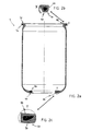
- Fig. 1 shows an air spring 1 for commercial vehicles with a cover 2, a rolling piston 3 and a rolling bellows 4 made of elastomeric material.
- the rolling piston 3 is made of plastic.
- the rolling bellows 4 has a fastening bead 5b with a bead core 6b at its end 4a facing the rolling piston 3.
- the bead core 6b according to the invention consists of plastic.
- the rolling bellows 4 has at its, the cover 2 facing the end 4a another mounting bead 5a with a bead core 6a, wherein this bead core 6a according to the invention consists of plastic.
- the connection of the rolling bellows 4 to the cover 2 and to the rolling piston 3 is known in the art.
- the cover 2 has a flange which forms the fastening bead 5a airtight embraces.
- the rolling piston has a conical seat on which the fastening bead 5b rests airtight.
- the bead core 6a, 6b is produced by injection molding, wherein the cross-sectional shape of the bead core 6a, 6b is selected such that it is optimally adaptable to the type of connection and thus to the airtightness of the rolling bellows 4 on the cover 2 or on the rolling piston 3.
- Fig. 2 shows a rolling bellows 4 with end fastening beads 5a and 5b, the bead cores 6a and 6b are made of plastic, which have an optimized cross-section.
Description
- Die Erfindung betrifft eine Luftfeder für Nutzfahrzeuge mit einem ersten Anschlussteil, insbesondere in Form eines Deckels, einem zweiten Anschlussteil in Form eines Abrollkolbens, und einem Rollbalg aus elastomerem Werkstoff, wobei ein erstes Ende des Rollbalges mittels eines ersten Befestigungsmittels an dem ersten Anschlussteil und ein zweites Ende des Rollbalges mittels eines zweiten Befestigungsmittels an dem Abrollkolben dichtend befestigbar ist.
- Derartige Luftfedern sind an sich bekannt und in großer Vielfalt in Nutzfahrzeugen, beispielsweise in Zugfahrzeugen und Anhängern, im Einsatz.
- Der Rollbalg selbst besteht aus einem elastomeren Material, vorzugsweise aus Gummi oder einem gummiähnlichem Kunststoff, und weist häufig endseitige Befestigungswülste auf
- Die Befestigung bzw. Einspannung des Rollbalges an den Anschlussteilen kann formschlüssig unter Verwendung von Klemmringen bzw. Spannringen oder durch einfaches Aufschieben der Befestigungswülste des Rollbalgs auf konusförmige Dichtflächen erfolgen. Die Befestigungswülste des Rollbalges sind üblicherweise mit eingebetteten zugfesten Wulstkernen bzw. Ringkörpern bzw. Piercekemen aus Stahl oder Stahldraht verstärkt und liegen unter der Wirkung des Innendruckes des Rollbalges an zugeordneten, konusförmigen Sitzflächen der Anschlussteile dichtend an.
- Die Anbindung zwischen Rollbalg und Anschlussteilen kann auch über verschraubbare Spannteller hergestellt werden, die den Rollbalg auf dem jeweiligen Anschlussteil, insbesondere auf dem Abrollkolben fixieren. Bei dieser Befestigung wird das Innenvolumen des Abrollkolbens für die Schraubverbindung genutzt, so dass dieses dann nicht mehr für eine Minimierung der Eigenfrequenz zur Verfügung steht. Eine Luftfeder mit einer solchen Anbindung des Rollbalges an den Abrollkolben soll nicht Gegenstand der vorliegenden Erfindung sein.
- Die Anbindung der Anschlussteile an den Rollbalg kann zudem durch eine Bördelplatte erfolgen, wobei eine derartige Bördelplatte üblicherweise um einen korrespondierenden Befestigungswulst des Rollbalges herum greift und so fest, luftdicht und unlösbar mit dem Rollbalg verbunden ist. Dadurch sind vorteilhaft große Zugkräfte übertragbar.
- Weiter ist bekannt, die Anschlussteilen, also den Abrollkolben und/oder den Deckel bzw. die Abdeckplatte, aus Kunststoff auszubilden. Dadurch sind die Anschlussteile vor Korrosion geschützt und haben vorteilhaft gegenüber herkömmlichen Anschlussteilen aus Metall ein viel geringeres Gewicht. Nachteilig daran ist, dass sich gezeigt hat, dass solche Luftfedern bei Temperaturschwankungen häufig nicht dicht sind.
- Ausgehend von diesem Stand der Technik liegt der Erfindung die Aufgabe zugrunde, eine gattungsgemäße Luftfeder, bei der das eine oder andere Anschlussteil aus Kunststoff besteht, derart weiterzuentwickeln, dass eine dichte Anbindung des Rollbalges am Anschlussteil auch bei Temperaturschwankungen sichergestellt ist.
- Diese Aufgabe wird erfindungsgemäß durch die Merkmale des Anspruchs 1 gelöst.
- Erfindungsgemäß ist vorgesehen, dass der Abrollkolben aus Kunststoff besteht und das zweite Befestigungsmittel nicht aus Metall ausgebildet ist und/oder dass das erste Anschlussteil aus Kunststoff besteht und das erste Befestigungsmittel nicht aus Metall ausgebildet ist.
- Es hat sich gezeigt, dass dadurch eine luftdichte und feste Verbindung zwischen Rollbalg und Anschlussteil bei jeder zu erwartenden Einsatztemperatur der Luftfeder erreicht werden kann. Eine solche Verbindung ist wirkungsvoll und kostengünstig herstellbar.
- Es hat sich gezeigt, dass bei einer Luftfeder mit einem Abrollkolben aus Kunststoff, an dem die Anbindung des Rollbalges über eine konusförmige Dichtfläche mittels wenigstens eines Befestigungsmittels aus Metall, üblicherweise mittels einer Gummi-Metallverbindung, erfolgt, die Dichtheit dieser so genannten Konussitz-Konstruktion nicht gewährleist ist.
- Der Erfindung liegt die Erkenntnis zugrunde, dass die Undichtheit auf die um den Faktor 10 unterschiedlichen Längenausdehnungskoeffizienten zwischen Kunststoff und Stahl zurückzuführen ist.
- Eine Weiterbildung der Erfindung sieht vor, dass der Rollbalg an seinem, dem Abrollkolben zugewandten Ende einen Befestigungswulst mit einem Wulstkern aufweist, wobei der Wulstkern aus Kunststoff besteht.
- Der Weiterbildung liegt ebenfalls die Erkenntnis zugrunde, dass bei einem Rollbalg mit einem endseitigen Befestigungswulst und metallischen Wulstkernen zur Anbindung an den Abrollkolben der Innendruck in der Luftfeder zwar üblicherweise den Befestigungswulst in die konusförmige Dichtfläche bzw. in den Konussitz des Abrollkolbens drückt, jedoch bei Temperaturänderungen sich aufgrund der unterschiedlichen Längenausdehnungskoeffizienten von Kunststoff und Metall die Durchmesser des Konussitzes auf der aus Kunststoff bestehenden Kolbenseite und des aus Metall bestehenden Wulstkernes auf der Rollbalgseite so stark verändern, dass bei geringen Innendruck in der Luftfeder der Konussitz nicht mehr abdichtet.
- Dadurch, dass der Wulstkern bzw. Piercekern aus Metall bzw. Stahl durch einen Wulstkern aus Kunststoff, vorzugsweise aus Polyamid, ersetzt wird, ergibt sich am Konussitz eine bevorzugte Materialpaarung aus einem Elastomer, nämlich des Rollbalges, und einem Kunststoff, nämlich des Abrollkolbens und des Wulstkernes, so dass sich der Abrollkolben und der Befestigungswulst der Rollbalges unter Temperatureinfluss im gleichen Maße ausdehnen. Die Dichtheit ist somit über den gesamten, beim Einsatz der Luftfeder zu erwartenden Temperaturbereich gegeben.
- Zweckmäßigerweise bestehen der Abrollkolben und der Wulstkern aus einem Kunststoff mit gleichem oder ähnlichem Längenausdehnungskoeffizienten bestehen. Dadurch wird die Dichtheit der Luftfeder im besonderen Maße gewährleistet. Die Materialien für die Anschlussteile und für die Befestigungsmittel, insbesondere für die Wulstkerne, können optimal aufeinander abgestimmt werden.
- Eine vorteilhafte Ausgestaltung der Erfindung sieht vor, dass der Rollbalg an seinem, dem ersten Anschlussteil zugewandten Ende einen Befestigungswulst mit einem Wulstkern aufweist, wobei der Wulstkern aus Kunststoff besteht.
- Vorzugsweise bestehen das erste Anschlussteil und der Wulstkern aus einem Kunststoff mit gleichem oder ähnlichem Längenausdehnungskoeffizienten bestehen. Die Materialien für die Anschlussteile und für die Befestigungsmittel, insbesondere für die Wulstkerne, können optimal aufeinander abgestimmt werden.
- Zweckmäßigerweise ist vorgehen, dass für die Verbindung zwischen Rollbalg und zweitem Anschlussteil und/oder dass für die Verbindung zwischen Rollbalg und erstem Anschlussteil jeweils eine konusförmige Dichtfläche bzw. ein Konussitz am Anschlussteil vorgesehen ist.
- Eine Weiterbildung der Erfindung sieht vor, dass der Wulstkern durch Spritzguss hergestellt ist.
- Eine vorteilhafte Ausgestaltung der Erfindung sieht vor, dass der Wulstkern Ausnehmungen oder Bohrungen aufweist, die bei einer Vulkanisation mit dem Elastomer des Rollbalges ausfüllbar sind.
- Eine Weiterbildung der Erfindung sieht vor, dass das die Querschnittsform des Befestigungsmittels oder des Wulstkerns derart wählbar ist, dass sie der dem Fachmann bekannten Anbindungsart des Rollbalgs am ersten und/oder zweiten Anschlussteil anpassbar ist. Vorzugsweise weist das Befestigungsmittel und/oder der Wulstkern einen runden, rechteckigen, ovalen, keilförmigen, halbovalen oder halbkreisförmigen Querschnitt aufweist.
- Eine vorteilhafte Ausgestaltung der Erfindung sieht vor, dass das das Befestigungsmittel und/oder der Wulstkern auf seiner Außenfläche eine zusätzliche Profilierung in Form von Haltevorsprüngen oder Haltenasen aufweist.
- Nachfolgend wird die Erfindung anhand zweier Ausführungsbeispiele erläutert, die in der der Zeichnung dargestellt sind. In dieser zeigen
-
Fig. 1 ein erstes undFig. 2 ein zweites Ausführungsbeispiel, und zwar: -
Fig. 1a eine Luftfeder im Längsschnitt undFig. 2a einen Rollbalg im Längsschnitt, -
Fig. 1b undFig. 2b jeweils die Detailansicht X und -
Fig. 1c undFig. 2c jeweils die Detailansicht Y. - In den beiden Figuren der Zeichnung sind gleiche Teile stets mit den gleichen Bezugszeichen versehen.
-
Fig. 1 zeigt eine Luftfeder 1 für Nutzfahrzeuge mit einem Deckel 2, einem Abrollkolben 3 und einem Rollbalg 4 aus elastomerem Werkstoff. Der Abrollkolben 3 besteht aus Kunststoff. - Der Rollbalg 4 weist an seinem, dem Abrollkolben 3 zugewandten Ende 4a einen Befestigungswulst 5b mit einem Wulstkern 6b auf. Der Wulstkern 6b besteht erfindungsgemäß aus Kunststoff.
- Der Rollbalg 4 weist an seinem, dem Deckel 2 zugewandten Ende 4a einen weiteren Befestigungswulst 5a mit einem Wulstkern 6a auf, wobei auch dieser Wulstkern 6a erfindungsgemäß aus Kunststoff besteht.
- Die Anbindung des Rollbalges 4 an den Deckel 2 und an den Abrollkolben 3 ist dem Fachmann bekannt. Der Deckel 2 weist eine Bördelung auf, die den Befestigungswulst 5a luftdicht umgreift. Der Abrollkolben weist dagegen einen Konussitz auf, an dem der der Befestigungswulst 5b luftdicht anliegt.
- Der Wulstkern 6a, 6b ist durch Spritzguss hergestellt, wobei die Querschnittsform des Wulstkerns 6a, 6b derart gewählt ist, dass sie der Anbindungsart und damit der Luftdichtheit des Rollbalgs 4 am Deckel 2 bzw. am Abrollkolben 3 optimal anpassbar ist.
-
Fig. 2 zeigt einen Rollbalg 4 mit endseitigen Befestigungswülsten 5a und 5b, deren Wulstkerne 6a und 6b aus Kunststoff bestehen, welche einen optimierten Querschnitt aufweisen. - So ist in
Fig. 2b gut zu erkennen, dass durch die gewählte, leicht ovale Querschnittsform des Wulstkernes 6a eine Optimierung erreicht wird, da die entsprechende Bördelung des Deckels 2 ebenfalls im Schnitt eher oval als rund ausgebildet ist. Auch die Querschnittform des Wulstkernes 6b inFig. 2c ist angepasst. Es ist deutlich zu erkennen, dass sich die Schlinge des Befestigungswulstes 5b sehr viel besser um den Wulstkern 6b legen kann, als dies beispielsweise bei einem quadratischen Querschnitt der Fall wäre. So kann vorteilhaft auf sonst notwendige Profilstreifen verzichtet werden. -
- 1
- Luftfeder
- 2
- erstes Anschlussteil (Deckel)
- 3
- zweites Anschlussteil (Abrollkolben)
- 4
- Rollbalg
- 4a
- erstes Ende des Rollbalges
- 4b
- zweites Ende des Rollbalges
- 5a
- erstes Befestigungsmittel (Befestigungswulst)
- 5b
- zweites Befestigungsmittel (Befestigungswulst)
- 6a
- Wulstkern
- 6b
- Wulstkern
Claims (7)
- Luftfeder (1) für Nutzfahrzeuge mit einem ersten Anschlussteil (2), insbesondere in Form eines Deckels, einem zweiten Anschlussteil (3) in Form eines Abrollkolbens und einem Rollbalg (4) aus elastomerem Werkstoff, wobei ein erstes Ende des Rollbalges (4a) mittels eines ersten Befestigungsmittels (5a) an dem ersten Anschlussteil (2) und ein zweites Ende des Rollbalges (4b) mittels eines zweiten Befestigungsmittels (5b) an dem Abrollkolbcn (3) dichtend befestigbar ist, wobei das zweite Befestigungsmittel (5b) keinen verschraubbaren Spannteller zur Fixierung des Rollbalges (4b) auf dem Abrollkolben (3) aufweist, dadurch gekennzeichnet, dass der Abrollkolben (3) aus Kunststoff besteht und das zweite Befestigungsmittel (5b) nicht aus Metall ausgebildet ist und/oder dass das erste Anschlussteil (2) aus Kunststoff besteht und das erste Befestigungsmittel (5a) nicht aus Metall ausgebildet ist und der Rollbalg (4),• an seinem ersten, dem ersten Anschlussteil (2) zugewandten Ende (4a) einen Befestigungswulst (5a) mit einem Wulstkern (6a) aufweist, wobei der Wulstkern (6a) aus Kunststoff besteht und der Kunstoff einen gleichem oder ähnlichen Längenausdehnungskoeffizient aufweist wie der Kunststoff des ersten Anschlussteils (2), und/oder• an seinem zweiten, dem Abrollkolben (3) zugewandten Ende (4b) einen Befestigungswulst (5b) mit einem Wulstkern (6b) aufweist, wobei der Wulstkern (6b) aus Kunststoff besteht und der Kunststoff einen gleichem oder ähnlichen Längenausdehnungskoeffizient aufweist wie der Kunststoff des Abrollkolbens (3).
- Luftfeder (1) nach Anspruch 1, dadurch gekennzeichnet, dass für die Verbindung zwischen Rollbalg (4) und zweitem Anschlussteil (3) und/oder dass für die Verbindung zwischen Rollbalg (4) und erstem Anschlussteil (2) jeweils ein Konussitz am Anschlussteil (3, 2) vorgesehen ist.
- Luftfeder (1) nach Anspruch 1 oder 2, dadurch gekennzeichnet, dass der Wulstkern (6a, 6b) durch Spritzguss hergestellt ist.
- Luftfeder (1) nach einem der Ansprüche 1 bis 3, dadurch gekennzeichnet, dass der Wulstkern (6a, 6b) Ausnehmungen oder Bohrungen aufweist, die bei einer Vulkanisation mit dem Elastomer des Rollbalges (4) ausfüllbar sind.
- Luftfeder (1) nach einem der Ansprüche 1 bis 4, dadurch gekennzeichnet, dass das die Querschnittsform des Befestigungsmittels (5a, 5b) oder des Wulstkerns (6a, 6b) derart wählbar ist, dass sie der dem Fachmann bekannten Anbindungsart des Rollbalgs (4) am ersten und/oder zweiten Anschlussteil (2, 3) anpassbar ist.
- Luftfeder (1) nach Anspruch 5, dadurch gekennzeichnet, dass das Befestigungs-mittel (5a, 5b) und/oder der Wulstkern (6a, 6b) einen runden, rechteckigen, ovalen, keilförmigen, halbovalen oder halbkreisförmigen Querschnitt aufweist.
- Luftfeder (1) nach einem der Ansprüche 1 bis 6, dadurch gekennzeichnet, dass das das Befestigungsmittel (5a, 5b) und/oder der Wulstkern (6a, 6b) auf seiner Außenfläche eine zusätzliche Profilierung in Form von Haltevorsprüngen oder Haltenasen aufweist.
Priority Applications (1)
| Application Number | Priority Date | Filing Date | Title |
|---|---|---|---|
| PL09744150T PL2376801T3 (pl) | 2008-12-11 | 2009-10-30 | Amortyzator powietrzny |
Applications Claiming Priority (2)
| Application Number | Priority Date | Filing Date | Title |
|---|---|---|---|
| DE102008055509A DE102008055509A1 (de) | 2008-12-11 | 2008-12-11 | Luftfeder |
| PCT/EP2009/064356 WO2010066508A1 (de) | 2008-12-11 | 2009-10-30 | Luftfeder |
Publications (2)
| Publication Number | Publication Date |
|---|---|
| EP2376801A1 EP2376801A1 (de) | 2011-10-19 |
| EP2376801B1 true EP2376801B1 (de) | 2015-10-28 |
Family
ID=41478793
Family Applications (1)
| Application Number | Title | Priority Date | Filing Date |
|---|---|---|---|
| EP09744150.5A Active EP2376801B1 (de) | 2008-12-11 | 2009-10-30 | Luftfeder |
Country Status (8)
| Country | Link |
|---|---|
| US (1) | US20110266728A1 (de) |
| EP (1) | EP2376801B1 (de) |
| CN (1) | CN102245926B (de) |
| BR (1) | BRPI0923350A2 (de) |
| DE (1) | DE102008055509A1 (de) |
| HU (1) | HUE026175T2 (de) |
| PL (1) | PL2376801T3 (de) |
| WO (1) | WO2010066508A1 (de) |
Families Citing this family (12)
| Publication number | Priority date | Publication date | Assignee | Title |
|---|---|---|---|---|
| DE102010000290A1 (de) * | 2010-02-03 | 2011-08-04 | ContiTech Luftfedersysteme GmbH, 30165 | Luftfedereinrichtung eines Schienenfahrzeuges |
| DE102010061163B4 (de) * | 2010-12-10 | 2019-04-11 | Contitech Luftfedersysteme Gmbh | Luftfeder für Nutzfahrzeuge mit einem Rollbalg aus elastomerem Werkstoff, dessen Enden jeweils einen Befestigungswulst aufweisen |
| US8733743B2 (en) * | 2010-12-23 | 2014-05-27 | Firestone Industrial Products Company, Llc | Gas spring piston, gas spring assembly and method |
| DE102012103358A1 (de) * | 2012-04-18 | 2013-10-24 | Contitech Luftfedersysteme Gmbh | Abrollkolben für einen Luftfederrollbalg |
| DE102012104964A1 (de) * | 2012-06-08 | 2013-12-12 | Contitech Luftfedersysteme Gmbh | Abrollkolben für einen Luftfederrollbalg |
| HUE027159T2 (en) * | 2012-07-25 | 2016-08-29 | Vibracoustic Cv Air Springs Gmbh | air suspension |
| US9261156B2 (en) * | 2013-02-14 | 2016-02-16 | Firestone Industrial Products Company, Llc | Flexible spring members as well as gas spring assemblies and methods of manufacture including same |
| DE102013206235A1 (de) | 2013-04-09 | 2014-10-09 | Continental Teves Ag & Co. Ohg | Luftfeder, insbesondere für Fahrzeuge |
| DE102015224651A1 (de) | 2015-12-09 | 2017-06-14 | Contitech Luftfedersysteme Gmbh | Elastomerer Gegenstand |
| DE102016100939B4 (de) * | 2016-01-20 | 2023-08-10 | Vibracoustic Cv Air Springs Gmbh | Luftfeder |
| CN109909695B (zh) * | 2019-03-26 | 2020-09-15 | 常州市顺承模具厂 | 橡胶空气弹簧的活塞成型方法 |
| CN112594317B (zh) * | 2020-11-05 | 2022-08-19 | 安徽红桥金属制造有限公司 | 一种方便盖板安装的空气弹簧 |
Citations (3)
| Publication number | Priority date | Publication date | Assignee | Title |
|---|---|---|---|---|
| EP0295392A2 (de) * | 1987-06-17 | 1988-12-21 | The Firestone Tire & Rubber Company | Wulstlose Luftfeder |
| WO2000073676A1 (en) * | 1999-05-28 | 2000-12-07 | The Goodyear Tire & Rubber Company | Air spring upper retainer |
| WO2007104671A1 (en) * | 2006-03-10 | 2007-09-20 | Trelleborg Automotive Uk Ltd. | Air spring with improved piston |
Family Cites Families (17)
| Publication number | Priority date | Publication date | Assignee | Title |
|---|---|---|---|---|
| FR1198448A (fr) * | 1957-01-17 | 1959-12-07 | Dunlop Rubber Co | Soufflets, diaphragmes et éléments flexibles similaires |
| US2922637A (en) * | 1957-05-29 | 1960-01-26 | Gen Motors Corp | Air spring bellows |
| DE2108694C2 (de) * | 1971-02-24 | 1986-03-13 | Continental Gummi-Werke Ag, 3000 Hannover | Luftfederbalg |
| US4787608A (en) * | 1987-01-15 | 1988-11-29 | The Firestone Tire & Rubber Company | Nylon bead reinforcement ring for fluid pressure devices |
| JPH06306785A (ja) * | 1993-04-19 | 1994-11-01 | Bridgestone Corp | 筒状弾性体 |
| AU2887097A (en) * | 1996-05-07 | 1997-11-26 | Phoenix Aktiengesellschaft | Pneumatic spring |
| US6386524B1 (en) * | 2000-02-15 | 2002-05-14 | Bfs Diversified Products, Llc | Pedestal mounted full reservoir air spring piston |
| US6942201B2 (en) * | 2002-08-02 | 2005-09-13 | Bfs Diversified Products, Llc | Volume reducing bead plate for air spring |
| DE102004030335A1 (de) * | 2004-06-23 | 2006-01-19 | Contitech Luftfedersysteme Gmbh | Luftfeder mit einem Abrollkolben und einem Rollbalg mit mindestens einem anvulkanisierten Befestigungsteil |
| DE102004050189A1 (de) * | 2004-10-15 | 2006-04-20 | Contitech Luftfedersysteme Gmbh | Luftfeder |
| ITMI20050211A1 (it) * | 2005-02-14 | 2006-08-15 | Stuani S P A | Pistone perfezionato per molle ad aria applicabile a sospensioni di autoveicoli rimorchi semirimorchi |
| DE102006033197A1 (de) * | 2006-07-18 | 2008-01-24 | Continental Aktiengesellschaft | Rollbalg für eine Luftfeder |
| EP2066916B1 (de) * | 2006-09-14 | 2012-04-25 | ContiTech Luftfedersysteme GmbH | Kunststoffdeckel für nutzfahrzeugluftfedern mit eingepasstem puffer |
| DE102006050020A1 (de) * | 2006-10-24 | 2008-04-30 | Continental Aktiengesellschaft | Rollbalg mit formschlüssiger Verbindung |
| WO2008097960A1 (en) * | 2007-02-05 | 2008-08-14 | Bfs Diversified Products, Llc | Piston for an air spring |
| EP2156068B1 (de) * | 2007-04-09 | 2015-08-26 | BFS Diversified Products, LLC | Gasfederanordnung und verfahren |
| DE102010000290A1 (de) * | 2010-02-03 | 2011-08-04 | ContiTech Luftfedersysteme GmbH, 30165 | Luftfedereinrichtung eines Schienenfahrzeuges |
-
2008
- 2008-12-11 DE DE102008055509A patent/DE102008055509A1/de not_active Withdrawn
-
2009
- 2009-10-30 HU HUE09744150A patent/HUE026175T2/en unknown
- 2009-10-30 BR BRPI0923350-4A patent/BRPI0923350A2/pt not_active Application Discontinuation
- 2009-10-30 EP EP09744150.5A patent/EP2376801B1/de active Active
- 2009-10-30 CN CN200980149962.0A patent/CN102245926B/zh active Active
- 2009-10-30 WO PCT/EP2009/064356 patent/WO2010066508A1/de active Application Filing
- 2009-10-30 PL PL09744150T patent/PL2376801T3/pl unknown
-
2011
- 2011-06-10 US US13/157,497 patent/US20110266728A1/en not_active Abandoned
Patent Citations (3)
| Publication number | Priority date | Publication date | Assignee | Title |
|---|---|---|---|---|
| EP0295392A2 (de) * | 1987-06-17 | 1988-12-21 | The Firestone Tire & Rubber Company | Wulstlose Luftfeder |
| WO2000073676A1 (en) * | 1999-05-28 | 2000-12-07 | The Goodyear Tire & Rubber Company | Air spring upper retainer |
| WO2007104671A1 (en) * | 2006-03-10 | 2007-09-20 | Trelleborg Automotive Uk Ltd. | Air spring with improved piston |
Also Published As
| Publication number | Publication date |
|---|---|
| WO2010066508A1 (de) | 2010-06-17 |
| US20110266728A1 (en) | 2011-11-03 |
| PL2376801T3 (pl) | 2016-03-31 |
| BRPI0923350A2 (pt) | 2015-07-21 |
| CN102245926A (zh) | 2011-11-16 |
| HUE026175T2 (en) | 2016-05-30 |
| CN102245926B (zh) | 2014-06-25 |
| EP2376801A1 (de) | 2011-10-19 |
| DE102008055509A1 (de) | 2010-06-17 |
Similar Documents
| Publication | Publication Date | Title |
|---|---|---|
| EP2376801B1 (de) | Luftfeder | |
| DE2337872C2 (de) | Gummi-Metall-Buchse | |
| DE102007026394A1 (de) | Drehfester Schlauchanschluss | |
| DE102014010899A1 (de) | Drehbare axial sichernde und druckfeste Leitungsverbindung | |
| EP3583341A1 (de) | Schelle | |
| DE102008055511A1 (de) | Luftfeder und Verfahren zur Montage | |
| DE102017202094A1 (de) | Luftfeder mit einem Kunststoffdeckel | |
| DE202007009801U1 (de) | Anordnung zum fluiddichten Verbinden von zwei Rohrenden aus unterschiedlichen Metallen | |
| EP0548581B1 (de) | Luftfeder mit einem wulstlosen Luftfederbalg aus elastomerem Werkstoff | |
| WO2015022102A1 (de) | Luftfederrollbalg mit stützgewebe | |
| WO2007054510A1 (de) | Verbindungssystem für leitungen, armaturen oder aggregate | |
| DE102008055512A1 (de) | Luftfeder | |
| EP1736683B1 (de) | Schlauchrollbalgluftfeder | |
| DE102012202908A1 (de) | Vorrichtung zum Abdichten eines Ringraumes zwischen einem Medienrohr/Kabel und einer Kernbohrung/Schutzrohr | |
| DE102007055077A1 (de) | Klemmkontur für ein druckbeaufschlagbares Bauteil und Spannmittel dafür | |
| DE102010036363A1 (de) | Rollbalg für eine Luftfeder | |
| WO2008009508A1 (de) | Rollbalg für eine luftfeder | |
| DE4118576A1 (de) | Luftfeder mit einem schlauchrollbalg aus elastomerem werkstoff | |
| EP1715221B1 (de) | Befestigung eines Endabschnitts eines Rollbalgs an einem Anschlussteil | |
| DE102017222588A1 (de) | Luftfeder | |
| DE102018122507A1 (de) | Anschlussvorrichtung für Rohrleitungen mit Leckageanzeige | |
| DE102016212825A1 (de) | Luftfeder mit Keilringbefestigung | |
| DE202011100611U1 (de) | Gummiprofile zur Verbindung von Dachrinnenstücken | |
| DE4243848A1 (de) | Schlauchschelle | |
| DE102008024109A1 (de) | Klemmkontur mit Dichtungsprofil |
Legal Events
| Date | Code | Title | Description |
|---|---|---|---|
| PUAI | Public reference made under article 153(3) epc to a published international application that has entered the european phase |
Free format text: ORIGINAL CODE: 0009012 |
|
| 17P | Request for examination filed |
Effective date: 20110711 |
|
| AK | Designated contracting states |
Kind code of ref document: A1 Designated state(s): AT BE BG CH CY CZ DE DK EE ES FI FR GB GR HR HU IE IS IT LI LT LU LV MC MK MT NL NO PL PT RO SE SI SK SM TR |
|
| DAX | Request for extension of the european patent (deleted) | ||
| 17Q | First examination report despatched |
Effective date: 20121205 |
|
| GRAP | Despatch of communication of intention to grant a patent |
Free format text: ORIGINAL CODE: EPIDOSNIGR1 |
|
| INTG | Intention to grant announced |
Effective date: 20150709 |
|
| GRAS | Grant fee paid |
Free format text: ORIGINAL CODE: EPIDOSNIGR3 |
|
| GRAA | (expected) grant |
Free format text: ORIGINAL CODE: 0009210 |
|
| AK | Designated contracting states |
Kind code of ref document: B1 Designated state(s): AT BE BG CH CY CZ DE DK EE ES FI FR GB GR HR HU IE IS IT LI LT LU LV MC MK MT NL NO PL PT RO SE SI SK SM TR |
|
| REG | Reference to a national code |
Ref country code: GB Ref legal event code: FG4D Free format text: NOT ENGLISH |
|
| REG | Reference to a national code |
Ref country code: CH Ref legal event code: EP |
|
| REG | Reference to a national code |
Ref country code: AT Ref legal event code: REF Ref document number: 758125 Country of ref document: AT Kind code of ref document: T Effective date: 20151115 |
|
| REG | Reference to a national code |
Ref country code: IE Ref legal event code: FG4D Free format text: LANGUAGE OF EP DOCUMENT: GERMAN |
|
| REG | Reference to a national code |
Ref country code: DE Ref legal event code: R096 Ref document number: 502009011772 Country of ref document: DE |
|
| REG | Reference to a national code |
Ref country code: LT Ref legal event code: MG4D |
|
| REG | Reference to a national code |
Ref country code: NL Ref legal event code: MP Effective date: 20151028 |
|
| PG25 | Lapsed in a contracting state [announced via postgrant information from national office to epo] |
Ref country code: IS Free format text: LAPSE BECAUSE OF FAILURE TO SUBMIT A TRANSLATION OF THE DESCRIPTION OR TO PAY THE FEE WITHIN THE PRESCRIBED TIME-LIMIT Effective date: 20160228 Ref country code: ES Free format text: LAPSE BECAUSE OF FAILURE TO SUBMIT A TRANSLATION OF THE DESCRIPTION OR TO PAY THE FEE WITHIN THE PRESCRIBED TIME-LIMIT Effective date: 20151028 Ref country code: LT Free format text: LAPSE BECAUSE OF FAILURE TO SUBMIT A TRANSLATION OF THE DESCRIPTION OR TO PAY THE FEE WITHIN THE PRESCRIBED TIME-LIMIT Effective date: 20151028 Ref country code: NO Free format text: LAPSE BECAUSE OF FAILURE TO SUBMIT A TRANSLATION OF THE DESCRIPTION OR TO PAY THE FEE WITHIN THE PRESCRIBED TIME-LIMIT Effective date: 20160128 Ref country code: NL Free format text: LAPSE BECAUSE OF FAILURE TO SUBMIT A TRANSLATION OF THE DESCRIPTION OR TO PAY THE FEE WITHIN THE PRESCRIBED TIME-LIMIT Effective date: 20151028 Ref country code: HR Free format text: LAPSE BECAUSE OF FAILURE TO SUBMIT A TRANSLATION OF THE DESCRIPTION OR TO PAY THE FEE WITHIN THE PRESCRIBED TIME-LIMIT Effective date: 20151028 |
|
| REG | Reference to a national code |
Ref country code: HU Ref legal event code: AG4A Ref document number: E026175 Country of ref document: HU |
|
| PG25 | Lapsed in a contracting state [announced via postgrant information from national office to epo] |
Ref country code: LV Free format text: LAPSE BECAUSE OF FAILURE TO SUBMIT A TRANSLATION OF THE DESCRIPTION OR TO PAY THE FEE WITHIN THE PRESCRIBED TIME-LIMIT Effective date: 20151028 Ref country code: BE Free format text: LAPSE BECAUSE OF NON-PAYMENT OF DUE FEES Effective date: 20151031 Ref country code: GR Free format text: LAPSE BECAUSE OF FAILURE TO SUBMIT A TRANSLATION OF THE DESCRIPTION OR TO PAY THE FEE WITHIN THE PRESCRIBED TIME-LIMIT Effective date: 20160129 Ref country code: SE Free format text: LAPSE BECAUSE OF FAILURE TO SUBMIT A TRANSLATION OF THE DESCRIPTION OR TO PAY THE FEE WITHIN THE PRESCRIBED TIME-LIMIT Effective date: 20151028 Ref country code: FI Free format text: LAPSE BECAUSE OF FAILURE TO SUBMIT A TRANSLATION OF THE DESCRIPTION OR TO PAY THE FEE WITHIN THE PRESCRIBED TIME-LIMIT Effective date: 20151028 Ref country code: PT Free format text: LAPSE BECAUSE OF FAILURE TO SUBMIT A TRANSLATION OF THE DESCRIPTION OR TO PAY THE FEE WITHIN THE PRESCRIBED TIME-LIMIT Effective date: 20160229 |
|
| REG | Reference to a national code |
Ref country code: CH Ref legal event code: PL |
|
| REG | Reference to a national code |
Ref country code: IE Ref legal event code: MM4A |
|
| PG25 | Lapsed in a contracting state [announced via postgrant information from national office to epo] |
Ref country code: CH Free format text: LAPSE BECAUSE OF NON-PAYMENT OF DUE FEES Effective date: 20151031 Ref country code: MC Free format text: LAPSE BECAUSE OF FAILURE TO SUBMIT A TRANSLATION OF THE DESCRIPTION OR TO PAY THE FEE WITHIN THE PRESCRIBED TIME-LIMIT Effective date: 20151028 Ref country code: CZ Free format text: LAPSE BECAUSE OF FAILURE TO SUBMIT A TRANSLATION OF THE DESCRIPTION OR TO PAY THE FEE WITHIN THE PRESCRIBED TIME-LIMIT Effective date: 20151028 Ref country code: LI Free format text: LAPSE BECAUSE OF NON-PAYMENT OF DUE FEES Effective date: 20151031 |
|
| REG | Reference to a national code |
Ref country code: DE Ref legal event code: R097 Ref document number: 502009011772 Country of ref document: DE |
|
| PG25 | Lapsed in a contracting state [announced via postgrant information from national office to epo] |
Ref country code: SK Free format text: LAPSE BECAUSE OF FAILURE TO SUBMIT A TRANSLATION OF THE DESCRIPTION OR TO PAY THE FEE WITHIN THE PRESCRIBED TIME-LIMIT Effective date: 20151028 Ref country code: RO Free format text: LAPSE BECAUSE OF FAILURE TO SUBMIT A TRANSLATION OF THE DESCRIPTION OR TO PAY THE FEE WITHIN THE PRESCRIBED TIME-LIMIT Effective date: 20151028 Ref country code: HU Free format text: LAPSE BECAUSE OF NON-PAYMENT OF DUE FEES Effective date: 20151031 Ref country code: DK Free format text: LAPSE BECAUSE OF FAILURE TO SUBMIT A TRANSLATION OF THE DESCRIPTION OR TO PAY THE FEE WITHIN THE PRESCRIBED TIME-LIMIT Effective date: 20151028 Ref country code: SM Free format text: LAPSE BECAUSE OF FAILURE TO SUBMIT A TRANSLATION OF THE DESCRIPTION OR TO PAY THE FEE WITHIN THE PRESCRIBED TIME-LIMIT Effective date: 20151028 Ref country code: EE Free format text: LAPSE BECAUSE OF FAILURE TO SUBMIT A TRANSLATION OF THE DESCRIPTION OR TO PAY THE FEE WITHIN THE PRESCRIBED TIME-LIMIT Effective date: 20151028 |
|
| PLBE | No opposition filed within time limit |
Free format text: ORIGINAL CODE: 0009261 |
|
| STAA | Information on the status of an ep patent application or granted ep patent |
Free format text: STATUS: NO OPPOSITION FILED WITHIN TIME LIMIT |
|
| GBPC | Gb: european patent ceased through non-payment of renewal fee |
Effective date: 20160128 |
|
| 26N | No opposition filed |
Effective date: 20160729 |
|
| REG | Reference to a national code |
Ref country code: FR Ref legal event code: ST Effective date: 20160902 |
|
| PG25 | Lapsed in a contracting state [announced via postgrant information from national office to epo] |
Ref country code: IE Free format text: LAPSE BECAUSE OF NON-PAYMENT OF DUE FEES Effective date: 20151030 Ref country code: GB Free format text: LAPSE BECAUSE OF NON-PAYMENT OF DUE FEES Effective date: 20160128 |
|
| PGRI | Patent reinstated in contracting state [announced from national office to epo] |
Ref country code: HU Effective date: 20160808 |
|
| PG25 | Lapsed in a contracting state [announced via postgrant information from national office to epo] |
Ref country code: SI Free format text: LAPSE BECAUSE OF FAILURE TO SUBMIT A TRANSLATION OF THE DESCRIPTION OR TO PAY THE FEE WITHIN THE PRESCRIBED TIME-LIMIT Effective date: 20151028 Ref country code: FR Free format text: LAPSE BECAUSE OF NON-PAYMENT OF DUE FEES Effective date: 20151228 |
|
| REG | Reference to a national code |
Ref country code: AT Ref legal event code: MM01 Ref document number: 758125 Country of ref document: AT Kind code of ref document: T Effective date: 20151030 |
|
| PG25 | Lapsed in a contracting state [announced via postgrant information from national office to epo] |
Ref country code: AT Free format text: LAPSE BECAUSE OF NON-PAYMENT OF DUE FEES Effective date: 20151030 Ref country code: PL Free format text: LAPSE BECAUSE OF NON-PAYMENT OF DUE FEES Effective date: 20151030 |
|
| PG25 | Lapsed in a contracting state [announced via postgrant information from national office to epo] |
Ref country code: BG Free format text: LAPSE BECAUSE OF FAILURE TO SUBMIT A TRANSLATION OF THE DESCRIPTION OR TO PAY THE FEE WITHIN THE PRESCRIBED TIME-LIMIT Effective date: 20151028 |
|
| PG25 | Lapsed in a contracting state [announced via postgrant information from national office to epo] |
Ref country code: CY Free format text: LAPSE BECAUSE OF FAILURE TO SUBMIT A TRANSLATION OF THE DESCRIPTION OR TO PAY THE FEE WITHIN THE PRESCRIBED TIME-LIMIT Effective date: 20151028 |
|
| PG25 | Lapsed in a contracting state [announced via postgrant information from national office to epo] |
Ref country code: MT Free format text: LAPSE BECAUSE OF FAILURE TO SUBMIT A TRANSLATION OF THE DESCRIPTION OR TO PAY THE FEE WITHIN THE PRESCRIBED TIME-LIMIT Effective date: 20151028 |
|
| PG25 | Lapsed in a contracting state [announced via postgrant information from national office to epo] |
Ref country code: LU Free format text: LAPSE BECAUSE OF NON-PAYMENT OF DUE FEES Effective date: 20151030 |
|
| PG25 | Lapsed in a contracting state [announced via postgrant information from national office to epo] |
Ref country code: MK Free format text: LAPSE BECAUSE OF FAILURE TO SUBMIT A TRANSLATION OF THE DESCRIPTION OR TO PAY THE FEE WITHIN THE PRESCRIBED TIME-LIMIT Effective date: 20151028 |
|
| PGFP | Annual fee paid to national office [announced via postgrant information from national office to epo] |
Ref country code: PL Payment date: 20181106 Year of fee payment: 13 |
|
| PGFP | Annual fee paid to national office [announced via postgrant information from national office to epo] |
Ref country code: IT Payment date: 20181024 Year of fee payment: 10 |
|
| PG25 | Lapsed in a contracting state [announced via postgrant information from national office to epo] |
Ref country code: IT Free format text: LAPSE BECAUSE OF NON-PAYMENT OF DUE FEES Effective date: 20191030 |
|
| PG25 | Lapsed in a contracting state [announced via postgrant information from national office to epo] |
Ref country code: HU Free format text: LAPSE BECAUSE OF NON-PAYMENT OF DUE FEES Effective date: 20191031 |
|
| REG | Reference to a national code |
Ref country code: DE Ref legal event code: R084 Ref document number: 502009011772 Country of ref document: DE |
|
| PGFP | Annual fee paid to national office [announced via postgrant information from national office to epo] |
Ref country code: DE Payment date: 20231031 Year of fee payment: 15 |