EP2375482B1 - Brennstoffzellensystem - Google Patents
Brennstoffzellensystem Download PDFInfo
- Publication number
- EP2375482B1 EP2375482B1 EP10187555A EP10187555A EP2375482B1 EP 2375482 B1 EP2375482 B1 EP 2375482B1 EP 10187555 A EP10187555 A EP 10187555A EP 10187555 A EP10187555 A EP 10187555A EP 2375482 B1 EP2375482 B1 EP 2375482B1
- Authority
- EP
- European Patent Office
- Prior art keywords
- fuel
- oxidising
- nozzle
- unit
- fuel cell
- Prior art date
- Legal status (The legal status is an assumption and is not a legal conclusion. Google has not performed a legal analysis and makes no representation as to the accuracy of the status listed.)
- Not-in-force
Links
Images



Classifications
-
- H—ELECTRICITY
- H01—ELECTRIC ELEMENTS
- H01M—PROCESSES OR MEANS, e.g. BATTERIES, FOR THE DIRECT CONVERSION OF CHEMICAL ENERGY INTO ELECTRICAL ENERGY
- H01M8/00—Fuel cells; Manufacture thereof
- H01M8/04—Auxiliary arrangements, e.g. for control of pressure or for circulation of fluids
- H01M8/04007—Auxiliary arrangements, e.g. for control of pressure or for circulation of fluids related to heat exchange
- H01M8/04014—Heat exchange using gaseous fluids; Heat exchange by combustion of reactants
- H01M8/04022—Heating by combustion
-
- C—CHEMISTRY; METALLURGY
- C01—INORGANIC CHEMISTRY
- C01B—NON-METALLIC ELEMENTS; COMPOUNDS THEREOF; METALLOIDS OR COMPOUNDS THEREOF NOT COVERED BY SUBCLASS C01C
- C01B3/00—Hydrogen; Gaseous mixtures containing hydrogen; Separation of hydrogen from mixtures containing it; Purification of hydrogen; Reversible storage of hydrogen
- C01B3/02—Production of hydrogen; Production of gaseous mixtures containing hydrogen
- C01B3/32—Production of hydrogen; Production of gaseous mixtures containing hydrogen by reaction of gaseous or liquid organic compounds with gasifying agents, e.g. water, carbon dioxide or air
- C01B3/34—Production of hydrogen; Production of gaseous mixtures containing hydrogen by reaction of gaseous or liquid organic compounds with gasifying agents, e.g. water, carbon dioxide or air by reaction of hydrocarbons with gasifying agents
- C01B3/38—Production of hydrogen; Production of gaseous mixtures containing hydrogen by reaction of gaseous or liquid organic compounds with gasifying agents, e.g. water, carbon dioxide or air by reaction of hydrocarbons with gasifying agents using catalysts
- C01B3/384—Production of hydrogen; Production of gaseous mixtures containing hydrogen by reaction of gaseous or liquid organic compounds with gasifying agents, e.g. water, carbon dioxide or air by reaction of hydrocarbons with gasifying agents using catalysts with external heating of the catalyst
-
- F—MECHANICAL ENGINEERING; LIGHTING; HEATING; WEAPONS; BLASTING
- F23—COMBUSTION APPARATUS; COMBUSTION PROCESSES
- F23D—BURNERS
- F23D14/00—Burners for combustion of a gas, e.g. of a gas stored under pressure as a liquid
- F23D14/20—Non-premix gas burners, i.e. in which gaseous fuel is mixed with combustion air on arrival at the combustion zone
- F23D14/22—Non-premix gas burners, i.e. in which gaseous fuel is mixed with combustion air on arrival at the combustion zone with separate air and gas feed ducts, e.g. with ducts running parallel or crossing each other
-
- H—ELECTRICITY
- H01—ELECTRIC ELEMENTS
- H01M—PROCESSES OR MEANS, e.g. BATTERIES, FOR THE DIRECT CONVERSION OF CHEMICAL ENERGY INTO ELECTRICAL ENERGY
- H01M8/00—Fuel cells; Manufacture thereof
- H01M8/06—Combination of fuel cells with means for production of reactants or for treatment of residues
- H01M8/0606—Combination of fuel cells with means for production of reactants or for treatment of residues with means for production of gaseous reactants
- H01M8/0612—Combination of fuel cells with means for production of reactants or for treatment of residues with means for production of gaseous reactants from carbon-containing material
- H01M8/0618—Reforming processes, e.g. autothermal, partial oxidation or steam reforming
-
- H—ELECTRICITY
- H01—ELECTRIC ELEMENTS
- H01M—PROCESSES OR MEANS, e.g. BATTERIES, FOR THE DIRECT CONVERSION OF CHEMICAL ENERGY INTO ELECTRICAL ENERGY
- H01M8/00—Fuel cells; Manufacture thereof
- H01M8/06—Combination of fuel cells with means for production of reactants or for treatment of residues
- H01M8/0606—Combination of fuel cells with means for production of reactants or for treatment of residues with means for production of gaseous reactants
- H01M8/0612—Combination of fuel cells with means for production of reactants or for treatment of residues with means for production of gaseous reactants from carbon-containing material
- H01M8/0625—Combination of fuel cells with means for production of reactants or for treatment of residues with means for production of gaseous reactants from carbon-containing material in a modular combined reactor/fuel cell structure
- H01M8/0631—Reactor construction specially adapted for combination reactor/fuel cell
-
- C—CHEMISTRY; METALLURGY
- C01—INORGANIC CHEMISTRY
- C01B—NON-METALLIC ELEMENTS; COMPOUNDS THEREOF; METALLOIDS OR COMPOUNDS THEREOF NOT COVERED BY SUBCLASS C01C
- C01B2203/00—Integrated processes for the production of hydrogen or synthesis gas
- C01B2203/02—Processes for making hydrogen or synthesis gas
- C01B2203/0205—Processes for making hydrogen or synthesis gas containing a reforming step
- C01B2203/0227—Processes for making hydrogen or synthesis gas containing a reforming step containing a catalytic reforming step
-
- C—CHEMISTRY; METALLURGY
- C01—INORGANIC CHEMISTRY
- C01B—NON-METALLIC ELEMENTS; COMPOUNDS THEREOF; METALLOIDS OR COMPOUNDS THEREOF NOT COVERED BY SUBCLASS C01C
- C01B2203/00—Integrated processes for the production of hydrogen or synthesis gas
- C01B2203/06—Integration with other chemical processes
- C01B2203/066—Integration with other chemical processes with fuel cells
-
- C—CHEMISTRY; METALLURGY
- C01—INORGANIC CHEMISTRY
- C01B—NON-METALLIC ELEMENTS; COMPOUNDS THEREOF; METALLOIDS OR COMPOUNDS THEREOF NOT COVERED BY SUBCLASS C01C
- C01B2203/00—Integrated processes for the production of hydrogen or synthesis gas
- C01B2203/08—Methods of heating or cooling
- C01B2203/0805—Methods of heating the process for making hydrogen or synthesis gas
- C01B2203/0811—Methods of heating the process for making hydrogen or synthesis gas by combustion of fuel
- C01B2203/0822—Methods of heating the process for making hydrogen or synthesis gas by combustion of fuel the fuel containing hydrogen
-
- C—CHEMISTRY; METALLURGY
- C01—INORGANIC CHEMISTRY
- C01B—NON-METALLIC ELEMENTS; COMPOUNDS THEREOF; METALLOIDS OR COMPOUNDS THEREOF NOT COVERED BY SUBCLASS C01C
- C01B2203/00—Integrated processes for the production of hydrogen or synthesis gas
- C01B2203/08—Methods of heating or cooling
- C01B2203/0805—Methods of heating the process for making hydrogen or synthesis gas
- C01B2203/0811—Methods of heating the process for making hydrogen or synthesis gas by combustion of fuel
- C01B2203/0827—Methods of heating the process for making hydrogen or synthesis gas by combustion of fuel at least part of the fuel being a recycle stream
-
- Y—GENERAL TAGGING OF NEW TECHNOLOGICAL DEVELOPMENTS; GENERAL TAGGING OF CROSS-SECTIONAL TECHNOLOGIES SPANNING OVER SEVERAL SECTIONS OF THE IPC; TECHNICAL SUBJECTS COVERED BY FORMER USPC CROSS-REFERENCE ART COLLECTIONS [XRACs] AND DIGESTS
- Y02—TECHNOLOGIES OR APPLICATIONS FOR MITIGATION OR ADAPTATION AGAINST CLIMATE CHANGE
- Y02E—REDUCTION OF GREENHOUSE GAS [GHG] EMISSIONS, RELATED TO ENERGY GENERATION, TRANSMISSION OR DISTRIBUTION
- Y02E60/00—Enabling technologies; Technologies with a potential or indirect contribution to GHG emissions mitigation
- Y02E60/30—Hydrogen technology
- Y02E60/50—Fuel cells
-
- Y—GENERAL TAGGING OF NEW TECHNOLOGICAL DEVELOPMENTS; GENERAL TAGGING OF CROSS-SECTIONAL TECHNOLOGIES SPANNING OVER SEVERAL SECTIONS OF THE IPC; TECHNICAL SUBJECTS COVERED BY FORMER USPC CROSS-REFERENCE ART COLLECTIONS [XRACs] AND DIGESTS
- Y02—TECHNOLOGIES OR APPLICATIONS FOR MITIGATION OR ADAPTATION AGAINST CLIMATE CHANGE
- Y02P—CLIMATE CHANGE MITIGATION TECHNOLOGIES IN THE PRODUCTION OR PROCESSING OF GOODS
- Y02P20/00—Technologies relating to chemical industry
- Y02P20/10—Process efficiency
Definitions
- the present invention relates to a fuel cell system comprising a reforming apparatus that includes a nozzle assembly that can efficiently jet anode off-gas containing oxidation fuel and hydrogen to an oxidizer.
- a steam reforming type reformer can be used to acquire high-concentration hydrogen from a fuel cell.
- a heat source is required because an endothermic reaction occurs in the steam reforming type reformer.
- a flame type or a catalyst type burner is mainly used.
- the catalyst type burner it is required to achieve a burner without a hot spot in the catalyst and backfire, that is, flashback in a catalytic reaction starter.
- the structure for preventing backfire is very important because the reactivity of the hydrogen contained in a large amount in the gas anode off-gas is very high.
- Embodiments of the invention provide a member that improves efficiency and operational safety of a fuel reformer, by reusing highly-reactive hydrogen by burning anode off-gas.
- the embodiments provide a burner that can efficiently mix and jet oxidation fuel and anode off-gas.
- the embodiments provide a member that can supply a fuel mixture without generating backfire in a structure recycling anode off-gas to the burner of a fuel reformer in order to increase efficiency of a fuel cell system.
- the first nozzle may be centrally located in the nozzle plate.
- the second nozzles may be uniformly distributed around the first nozzle.
- the connecting unit may comprise a first channel between the first nozzle and an anode off-gas inlet and a second channel surrounding the first channel and connecting the plurality of second nozzles with the oxidising unit fuel inlet.
- the second channel may comprise a first portion comprising a continuous channel for receiving the oxidising unit fuel and a second portion comprising a plurality of separate channels connected to the continuous channel for providing the oxidising unit fuel to the plurality of second nozzles.
- the relative areas of the first and second nozzles may be arranged so that the oxidising unit fuel is supplied in a ratio of one to three and a half times the volume of the anode off-gas.
- the maximum diameter of the first nozzle may be 2.5mm and the maximum diameter of each of the second nozzles may be 1.5mm.
- the oxidising unit may comprise a housing that is closed by the nozzle plate of the nozzle assembly and an oxidising portion within the housing.
- the oxidising portion may comprise an oxidation catalyst.
- the reformer may comprise a vessel for receiving a fuel to be reformed, the vessel being closed at one end by a lower plate, a reforming portion for converting the fuel to be reformed to a reformate and means within the vessel for receiving and discharging the reformate, wherein the reformer is disposed within the housing of the oxidising unit.
- the lower plate may be arranged relative to the nozzle plate such that the anode off-gas and the oxidising unit fuel mix in the region between the lower plate and the nozzle plate and flow around the reformer into the oxidising portion of the oxidising unit.
- the fuel reforming apparatus may further comprise an oxidising unit plate between the lower plate and the nozzle plate, the oxidising unit plate including third nozzles for providing a mixture of the anode off-gas and the oxidising unit fuel to the oxidising portion.
- the total area of the third nozzles may be between one to four times the sum of the total areas of the first nozzles and the second nozzles.
- Walls forming a space between the third nozzles and the oxidising portion may be arranged such that the space gradually widens from the third nozzles towards the oxidising portion.
- the fuel reforming apparatus may further comprise an evaporator arranged to receive exhaust heat from the oxidising unit to convert water to steam and to provide the steam to the reformer with the fuel to be reformed.
- embodiments of the present invention makes it possible to increase the entire efficiency of the fuel cell by supplying heat needed for reforming, using the anode off-gas, stably burn the anode off-gas without backfire and prevent deterioration of the fuel reformer due to concentration of thermal energy by preventing channeling in a thermal distribution diagram.
- Typical fuel cells are composed of a fuel converter (reformer and reactor) reforming and supplying fuel and a fuel cell module.
- the fuel cell module implies an assembly including a fuel cell stack converting chemical energy into electric energy and thermal energy in an electrochemical method.
- the present invention relates to an oxidizing unit supplying heat to a reformer and a nozzle assembly supplying fuel to the oxidizing unit.
- a reformer supplying heat to a reformer
- a nozzle assembly supplying fuel to the oxidizing unit.
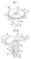
- a nozzle assembly 100 also referred to as a burner nozzle assembly, is first described with reference to FIGS. 1 to 3 .
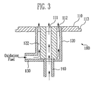
- the nozzle assembly 100 can be divided into a nozzle plate 110, a channel unit 120, an oxidation fuel introducer 130, and an AOG introducer 140.
- the oxidation fuel introducer 130 and the AOG introducer 140 are pipes through which fuel for an oxidizing unit 200 (see FIG. 4 ) is supplied, this fuel being referred to herein as oxidation fuel, or as oxidising unit fuel.
- the oxidation fuel is supplied to the nozzle assembly 100 through the oxidation fuel introducer 130 and the anode off-gas created in the operation of the fuel cell is supplied to the nozzle assembly 100 through the AOG introducer 140.
- the nozzle plate 110 is formed in a circular plate or a predetermined-shaped plate. It is preferable that the nozzle plate 110 is made of a heat resistant material enduring high temperatures of about 1000°C.
- the AOG nozzle 111 and the oxidation fuel nozzle 112 are bored through the nozzle plate 110.
- the AOG nozzle 111 is formed at the centre of the nozzle plate 110 and the oxidation fuel nozzle 112 is disposed radially at a predetermined distance from the centre of the AOG nozzle 111. Further, the anode off-gas and the oxidation fuel are supplied into the oxidizing unit 200 through the AOG nozzle 111 and the oxidation fuel nozzle 112, respectively.
- FIG. 2B is a transverse cross-sectional view taken along line III-III' in FIG. 2A
- FIG. 2C is a transverse cross-sectional view taken along line IV-IV' in FIG. 2A .
- the channel unit 120 is formed by inserting a pipe from the oxidation fuel introducer 130 and the AOG introducer 130 to the AOG nozzle 111 and the oxidation fuel nozzle 112 formed in the nozzle plate 110, or the channel unit 120 has connecting channels therein.
- the anode off-gas is delivered from the AOG introducer 140 to the AOG nozzle 111 through an AOG channel 121.
- the oxidation fuel is distributed and delivered to each oxidation fuel nozzle 112 from the oxidation fuel introducer 130 through oxidation fuel channels 122.
- the oxidation fuel channel 122 as shown in FIGS. 2B and 2C , may have different upper and lower structures.
- the lower portion 122b of the oxidation fuel channel may have a space that can provide a circumferentially continuous channel to receive oxidation fuel and deliver it under each oxidation fuel nozzle 112, and the upper portion 122a of the oxidation fuel channel may have a plurality of discontinuous spaces to distribute and deliver the oxidation fuel from the lower portion 122b of the oxidation fuel channel to each oxidation fuel nozzle 112.
- the nozzle assembly 100 is important in the configuration and position of the AOG nozzle 111 and the oxidation fuel nozzle 112 on the nozzle plate 110, it is possible to modify in the same operational range the configuration of the oxidation fuel introducer 130, the configuration of the AOG introducer 140, the configuration of the channel unit 120, and the connection relationships between them.
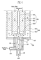
- the oxidizing unit 200 and the reformer 300 are described with reference to FIG. 4 .
- a reformer 300 is provided for acquiring hydrogen, which is a raw substance to directly use to produce electricity in a fuel cell from a hydrocarbon-based fuel (hereafter, referred to as 'main fuel').
- 'main fuel' a hydrocarbon-based fuel
- a steam reforming type although it is possible to increase the output of the cell and acquire high-concentration hydrogen, it is required to supply heat from the outside due to the endothermic reaction, which is achieved by the oxidizing unit 200.
- the reformer 300 is formed of a double hollow cylinder.
- the outer pipe, or vessel, 302, the outermost part of the reformer, is closed at the lower end with a reformer lower plate 303 and has an inner pipe, or other discharge means, 301 with the lower end open therein.
- the main fuel makes a steam reforming reaction while flowing down through a reforming-reacting portion 310 disposed between the reformer inner pipe 301 and the reformer outer pipe 302, and then is delivered upward through the reformer inner pipe 301.
- the oxidizing unit 200 of this embodiment has a hollow cylindrical shape and is preferably closed by the nozzle plate 110.
- the reformer 300 is disposed inside the oxidizing unit 200.
- the reformer lower plate 303 maintains a predetermined distance from the nozzle plate 110 and the reformer outer pipe 302 also maintains a predetermined distance from the oxidizing unit body 201.
- the anode off-gas and the oxidation fuel discharged from the AOG nozzle 111 and the oxidation fuel nozzle 112 flow through the space defined between the reformer 300 and the oxidizing unit 200.
- the anode off-gas and the oxidation fuel are mixed and flow upward along the space between the reformer outer pipe 302 and the oxidizing unit body 201 after passing under the reformer lower plate 303, and then oxidize and generate heat in the oxidizing portion 210 between the reformer outer pipe 302 and the oxidizing unit body 201.
- At least any one of PdAl 2 O 3 , NiO, CuO, CeO, Al 2 O 3 , Rh, Pd, and Pt can be used as a catalyst in the oxidizing portion 210. Meanwhile, the configuration of the upper portions of the oxidizing unit 200 and the reformer 300 is not shown for the convenience of description in this embodiment.
- an LPG hydrocarbon-based fuel
- air mixture can be used as the oxidation fuel.
- the anode off-gas contains a large amount of hydrogen that is discharged without reacting with the fuel electrode of the fuel cell. Since the hydrogen is highly reactive, backfire is likely to be generated when the anode off-gas is directly supplied into the oxidizing unit. Therefore, the possibility of backfire is reduced by mixing the anode off-gas containing a large amount of high-reactive hydrogen with oxidation fuel having relatively low reactivity (e.g. a gas mixture of LPG and air) and supplying the mixture into the oxidizing unit.
- oxidation fuel having relatively low reactivity
- the anode off-gas is larger in diffusion speed than the oxidation fuel, when the anode off-gas and the oxidation fuel are supplied under the same pressure. Accordingly, as shown in FIG. 4 , the anode off-gas is mixed with the oxidation fuel discharged from the oxidation fuel nozzle 112 and then flows into the oxidizing portion 210, after being supplied from the AOG nozzle 111 into the oxidizing unit 200.
- the hydrogen-rich anode off-gas is large in diffusion speed, such that the anode off-gas is injected into oxidation fuel having large concentration; therefore the anode off-gas and the oxidation fuel are sufficiently mixed before reaching the oxidizing portion 210.
- the mole number of the molecules of the hydrogen per unit volume of the fuel containing the mixture of the anode off-gas and the oxidation fuel reduces in proportion to the mixed ratio of the oxidation fuel, relatively to the anode off-gas itself, and possibility of backfire is correspondingly reduced.
- the mixing ratio of the anode off-gas and the oxidation fuel can be adjusted by the diameter of the AOG nozzle 111, the diameter and the number of the oxidation fuel nozzles 112, under the assumption that the supply pressures of the anode off-gas and the oxidation fuel are the same.
- the diameter of the AOG nozzle 111 increases, the mixing ratio of the anode off-gas increases, and as the diameter or the number of the oxidation fuel nozzles 112 increases, the mixing ratio of the oxidation fuel can be increased.
- the AOG nozzle 111 cannot be infinitely increased due to the possibility of backfire, whereas when the AOG nozzle 111 is too small in size, the amount of anode off-gas supplied becomes too small, which causes a problem.
- the AOG nozzle 111 has a maximum diameter of preferably 2.5mm, in consideration of the possibility of backfire and the amount of anode off-gas supplied whereas the oxidation fuel nozzle 112 has a maximum diameter of preferably 1.5mm.
- the oxidation fuel nozzle 112 it can be determined in accordance with the area of the AOG nozzle 111, in consideration of the mixing ratio. It is preferable that the oxidation fuel is supplied in a proportion of one to three and a half times the volume of the anode off-gas.
- the discharge area of each nozzle is as follows.
- the oxidation fuel nozzles 112 it is preferable to dispose the oxidation fuel nozzles 112 at a regular distance such that the anode off-gas and the oxidation fuel are uniformly mixed, in order to prevent channeling in the thermal distribution diagram in operating the oxidizing unit 200 due to disproportionate distribution of the hydrogen.
- This embodiment relates to the lower structure of an oxidizing unit which reinforces mixing of the anode off-gas and the oxidation fuel.
- An oxidizing unit 200a is closed at the lower end by a nozzle plate 110 and has an oxidizing unit lower plate 203 disposed at a predetermined distance from an oxidizing unit body 201 having the nozzle plate 111 to close the lower portion of the oxidizing unit body 201. Therefore, a circular plate-shaped space can be defined between the oxidizing unit plate 203 and the nozzle plate 110. Further, mixed oxidation fuel nozzles 205 are formed through the oxidizing unit lower plate 203. The mixed oxidizing fuel nozzles 205 are disposed at a predetermined distance from the oxidizing unit lower plate 203 and biased to the oxidizing unit body 201.
- the diameter of the nozzle plate 110 of the nozzle assembly 100 is determined such that the nozzle plate 110 can be inserted in a small gap from under the oxidizing unit body 201.
- a stepped portion 113 (see FIG. 1 ) having a larger diameter than the nozzle plate 110 is formed around the nozzle plate 110 such that the nozzle plate 110 is inserted by a predetermined depth in the oxidizing unit body 201. It is preferable to combine the nozzle plate 1110 and the oxidizing unit body 201 and then seal it by welding.
- a predetermined space A2 having a circular plate shape is defined between the nozzle plate 110 and the oxidizing unit lower plate 203.
- the anode off-gas and the oxidation fuel are mixed while flowing to the oxidizing portion 210 through the channel, in which the outlet of the mixing space A2 is blocked by the oxidation fuel nozzle 205, such that the number of collisions of the molecules in the anode off-gas and the oxidation fuel increases. Accordingly, the anode off-gas and the oxidation fuel can be mixed more easily than in example 1.
- the diameter of the mixed oxidation fuel nozzle 205 depends on the supply amount of mixed oxidation fuel. That is, the total area of the mixed oxidation fuel nozzles 205 is preferably one or four times the sum of the total area of the AOG nozzle and the oxidation fuel nozzles. When it is under one time, unnecessary pressure is generated in the region A2, and when it is above four times, the effect of mixing by the nozzle according to this embodiment is reduced. For example, as exemplified above, when the diameter of the AOG nozzle is 2.5mm and the diameter of the oxidation fuel nozzle is 1mm and the number is 12, the diameter and the number of the mixed oxidation fuel nozzle 205 can be set to 1.5mm and 30, respectively.
- the total area of the AOG nozzle 111 and the oxidation fuel nozzles 112 is 4.5625 ⁇ and the total area of the mixed oxidation fuel nozzles 205 is 16.875 ⁇ , which is four times the sum of the area of the AOG nozzle 111 and the oxidation fuel nozzles 112.
- the anode off-gas and the oxidation fuel are first mixed by collision of supplied gases around each nozzle and then secondarily mixed while flowing to the mixed oxidation fuel nozzles 205 through the channel.
- FIG. 7 Another embodiment of the present invention is described with reference to FIG. 7 . This embodiment is meaningful in narrowing the space around the mixed oxidation fuel nozzles 205, as compared with the example 2.
- the lower end of an oxidizing unit body 201b is bent inside and the lower end of a reformer external pipe 301b is bent outside; thereafter, the lower end of the oxidizing unit body 201b is sealed by attaching a nozzle plate 110.
- FIG. 8 Another embodiment including an evaporator 400 is described with reference to FIG. 8 .
- the evaporator 400 is provided to evaporate water supplied to the reformer 300 using the steam reforming method, using the thermal energy of the exhaust discharged from an oxidizing unit 200a.
- the evaporator 400 has a structure in which a step along which water flows and a step through which the exhaust flows are alternately disposed to increase the heat exchange efficiency of the exhaust.
- the anode off-gas and the oxidation fuel are supplied through the AOG nozzle 111 and the oxidation fuel nozzle 112, respectively, mixed in a space A2 defined between the oxidizing lower plate 203 and the nozzle plate 111, and then discharged through the mixed oxidation fuel nozzle 205.
- the discharged mixed oxidation fuel is oxidized in the oxidizing portion 210 and generates heat, and the exhaust created after the oxidation converts the water supplied from a water supplier 402 into steam by transmitting the remaining heat to the evaporator, and then is discharged through an exhaust outlet 404 of the evaporator 400.
- the converted steam is mixed with main fuel supplied from main fuel inlet 401 through a connecting pipe 403 and then flows to a reformer 300.
- the main fuel and the steam are converted into a hydrogen-rich reformate by the steam reforming method and then flows to a reactor (not shown) for reducing carbon monoxide or the fuel electrode of the fuel cell through a reformer inner pipe 301.
Landscapes
- Chemical & Material Sciences (AREA)
- Engineering & Computer Science (AREA)
- Chemical Kinetics & Catalysis (AREA)
- Combustion & Propulsion (AREA)
- Life Sciences & Earth Sciences (AREA)
- Sustainable Energy (AREA)
- General Chemical & Material Sciences (AREA)
- Electrochemistry (AREA)
- Manufacturing & Machinery (AREA)
- Sustainable Development (AREA)
- Organic Chemistry (AREA)
- Health & Medical Sciences (AREA)
- General Health & Medical Sciences (AREA)
- Inorganic Chemistry (AREA)
- Mechanical Engineering (AREA)
- General Engineering & Computer Science (AREA)
- Hydrogen, Water And Hydrids (AREA)
- Fuel Cell (AREA)
- Combustion Of Fluid Fuel (AREA)
Claims (15)
- Brennstoffzellensystem, umfassend:eine Brennstoffzelle, die Anodenabgas erzeugt; undeine Brennstoffreformiervorrichtung, umfassend:dadurch gekennzeichnet, dasseinen Reformer (300);eine Oxidationseinheit (200, 200a) zum Abgeben von Wärme an den Reformer;eine Oxidationseinheit-Brennstoffzufuhr zum Abgeben von Oxidationseinheit-Brennstoff an die Oxidationseinheit; undeine Düsenanordnung zum Abgeben des Anodenabgases und des Oxidationseinheit-Brennstoffs an die Oxidationseinheit,
die Düsenanordnung umfasst:eine Düsenplatte (110) umfassend eine erste Düse (111) zum Abgeben des Anodenabgases an die Oxidationseinheit und eine Vielzahl von die erste Düse umgebenden zweiten Düsen (112) zum Abgeben des Oxidationseinheit-Brennstoffs an die Oxidationseinheit; undeine sich von der Düsenplatte (110) aus erstreckende Verbindungseinheit (120) zum Abgeben des Anodenabgases von der Brennstoffzelle an die erste Düse (111) und des Oxidationseinheit-Brennstoffs von der Oxidationseinheit-Brennstoffzufuhr an die Vielzahl der zweiten Düsen (112). - Brennstoffzellensystem nach Anspruch 1, wobei die Oxidationseinheit umfasst:ein Gehäuse (201), das durch die Düsenplatte (110) der Düsenanordnung verschlossen ist; undeinen Oxidationsabschnitt (210) innerhalb des Gehäuses (210).
- Brennstoffzellensystem nach Anspruch 2, wobei der Oxidationsabschnitt (210) einen Oxidationskatalysator umfasst.
- Brennstoffzellensystem nach Anspruch 1, 2 oder 3, wobei der Reformer (300) umfasst:einen Behälter (302) zum Aufnehmen eines zu reformierenden Brennstoffs, wobei der Behälter an einem Ende durch eine untere Platte (303) verschlossen ist;einen Reformierabschnitt (310) zum Umwandeln des zu reformierenden Brennstoffs in ein Reformat; undMittel (301) innerhalb des Behälters zum Aufnehmen und Ablassen des Reformats, wobei der Reformer innerhalb des Gehäuses (201) der Oxidationseinheit angeordnet ist.
- Brennstoffzellensystem nach Anspruch 4, wobei die untere Platte (303) relativ zur Düsenplatte (110) derart angeordnet ist, dass sich das Anodenabgas und der Oxidationseinheit-Brennstoff im Bereich zwischen der unteren Platte (303) und der Düsenplatte (110) vermischen und um den Reformer in den Oxidationsabschnitt (210) der Oxidationseinheit (200) strömen.
- Brennstoffzellensystem nach Anspruch 4, ferner umfassend eine Oxidationseinheit-Platte (203) zwischen der unteren Platte (303) und der Düsenplatte (110), wobei die Oxidationseinheit-Platte dritte Düsen (205) zum Abgeben eines Gemisches aus dem Anodenabgas und dem Oxidationseinheit-Brennstoff an den Oxidationsabschnitt (210) umfasst.
- Brennstoffzellensystem nach Anspruch 6, wobei die Gesamtfläche der dritten Düsen zwischen ein bis vier Mal die Summe der Gesamtflächen der ersten Düsen und der zweiten Düsen beträgt.
- Brennstoffzellensystem nach Anspruch 6 oder 7, wobei einen Raum zwischen den dritten Düsen und dem Oxidationsabschnitt (210) bildende Wände (201 b, 301 b) derart angeordnet sind, dass sich der Raum sukzessiv von den dritten Düsen (210) zum Oxidationsabschnitt (210) hin verbreitert.
- Brennstoffzellensystem nach einem der vorstehenden Ansprüche, ferner umfassend einen Verdampfer (400), der zum Aufnehmen von Abgaswärme aus der Oxidationseinheit (200a) angeordnet ist, um Wasser in Dampf umzuwandeln und den Dampf an den Reformer (300) mit dem zu reformierenden Brennstoff abzugeben.
- Brennstoffzellensystem nach einem der vorstehenden Ansprüche, wobei sich die erste Düse (111) mittig in der Düsenplatte (110) befindet.
- Brennstoffzellensystem nach einem der vorstehenden Ansprüche, wobei die zweiten Düsen (112) gleichmäßig um die erste Düse (111) herum verteilt sind.
- Brennstoffzellensystem nach einem der vorstehenden Ansprüche, wobei die Verbindungseinheit (120) umfasst:einen ersten Kanal (121) zwischen der ersten Düse (111) und einem Anodenabgaseinlass (140); undeinen den ersten Kanal umgebenden zweiten Kanal (122), der die Vielzahl von zweiten Düsen (112) mit dem Oxidationseinheit-Brennstoffeinlass (130) verbindet.
- Brennstoffzellensystem nach Anspruch 12, wobei der zweite Kanal (122) umfasst:einen ersten Abschnitt (122b) umfassend einen durchgehenden Kanal zum Aufnehmen des Oxidationseinheit-Brennstoffs; undeinen zweiten Abschnitt (122a) umfassend eine Vielzahl von mit dem durchgehenden Kanal verbundenen separaten Kanälen zum Abgeben des Oxidationseinheit-Brennstoffs an die Vielzahl von zweiten Düsen.
- Brennstoffzellensystem nach einem der vorstehenden Ansprüche, wobei die relativen Flächen der ersten und zweiten Düsen so angeordnet sind, dass der Oxidationseinheit-Brennstoff in einem Verhältnis von eins zu drei und ein halbes Mal des Volumens des Anodenabgases zugeführt wird.
- Brennstoffzellensystem nach einem der vorstehenden Ansprüche, wobei der maximale Durchmesser der ersten Düse 2,5 mm und der maximale Durchmesser jeder der zweiten Düsen 1,5 mm beträgt.
Applications Claiming Priority (1)
| Application Number | Priority Date | Filing Date | Title |
|---|---|---|---|
| US34235310P | 2010-04-12 | 2010-04-12 |
Publications (2)
| Publication Number | Publication Date |
|---|---|
| EP2375482A1 EP2375482A1 (de) | 2011-10-12 |
| EP2375482B1 true EP2375482B1 (de) | 2013-01-09 |
Family
ID=44310209
Family Applications (1)
| Application Number | Title | Priority Date | Filing Date |
|---|---|---|---|
| EP10187555A Not-in-force EP2375482B1 (de) | 2010-04-12 | 2010-10-14 | Brennstoffzellensystem |
Country Status (4)
| Country | Link |
|---|---|
| US (1) | US8603203B2 (de) |
| EP (1) | EP2375482B1 (de) |
| JP (1) | JP5317136B2 (de) |
| KR (1) | KR101240688B1 (de) |
Families Citing this family (5)
| Publication number | Priority date | Publication date | Assignee | Title |
|---|---|---|---|---|
| JP6334411B2 (ja) | 2011-12-21 | 2018-05-30 | スリーエム イノベイティブ プロパティズ カンパニー | 触媒システム |
| DE112013005790B4 (de) | 2012-12-05 | 2023-07-06 | Deutsches Zentrum für Luft- und Raumfahrt e.V. | Verfahren zum Betreiben eines Verbrennungssystems und Verbrennungssystem |
| AT513932B1 (de) * | 2013-02-04 | 2016-11-15 | Avl List Gmbh | Katalysatoreinheit für ein Hochtemperatur-Brennstoffzellensystem |
| CN106287639B (zh) * | 2015-05-15 | 2019-05-21 | 宁德市维克贸易有限公司 | 蒸汽变换氢氧预混清洁锅炉 |
| DE102017001567B4 (de) * | 2017-02-20 | 2022-06-09 | Diehl Aerospace Gmbh | Verdampfer und Brennstoffzellenanordnung |
Family Cites Families (34)
| Publication number | Priority date | Publication date | Assignee | Title |
|---|---|---|---|---|
| US2942655A (en) | 1955-04-27 | 1960-06-28 | Fisher Scientific Co | Gas burner |
| US3531263A (en) * | 1968-08-05 | 1970-09-29 | United Aircraft Corp | Integrated reformer unit |
| US3909299A (en) * | 1973-10-01 | 1975-09-30 | United Technologies Corp | Fuel cell system including reform reactor |
| US4504447A (en) * | 1981-11-13 | 1985-03-12 | The United States Of America As Represented By The United States Department Of Energy | Slab reformer |
| US4430304A (en) * | 1981-11-13 | 1984-02-07 | The United States Of America As Represented By The United States Department Of Energy | Slab reformer |
| US4861348A (en) * | 1986-10-08 | 1989-08-29 | Hitachi, Ltd. | Fuel reforming apparatus |
| US4909808A (en) * | 1987-10-14 | 1990-03-20 | The United States Of America As Represented By The Administrator Of The National Aeronautics And Space Administration | Steam reformer with catalytic combustor |
| EP0615949B1 (de) * | 1993-03-16 | 1999-09-15 | Tokyo Gas Co., Ltd. | Vorrichtung zur Herstellung von Wasserstoff |
| CA2181292C (en) | 1995-07-17 | 2008-07-15 | Louis C. Philippe | Combustion process and apparatus therefor containing separate injection of fuel and oxidant streams |
| GB2316161A (en) * | 1996-08-05 | 1998-02-18 | Boc Group Plc | Oxygen-fuel swirl burner |
| US6221117B1 (en) | 1996-10-30 | 2001-04-24 | Idatech, Llc | Hydrogen producing fuel processing system |
| US20020006535A1 (en) | 1996-11-01 | 2002-01-17 | Richard Woods | Integrated power module |
| ATE317529T1 (de) | 1999-08-17 | 2006-02-15 | Nippon Furnace Kogyo Kk | Verbrennungsverfahren und brenner |
| DE10119083C1 (de) * | 2001-04-19 | 2002-11-28 | Joachim Alfred Wuenning | Kompakt-Dampf-Reformer |
| EP1327821A1 (de) * | 2001-12-25 | 2003-07-16 | Matsushita Electric Industrial Co., Ltd. | Brenner für Wasserstofferzeugungssystem und Wasserstofferzeugungssystem mit demselben |
| DE50305340D1 (de) * | 2002-03-25 | 2006-11-23 | Viessmann Werke Kg | Vorrichtung zur erzeugung von wasserstoff |
| US20030223926A1 (en) | 2002-04-14 | 2003-12-04 | Edlund David J. | Steam reforming fuel processor, burner assembly, and methods of operating the same |
| US6604937B1 (en) | 2002-05-24 | 2003-08-12 | Praxair Technology, Inc. | Coherent jet system with single ring flame envelope |
| JP2004149407A (ja) | 2002-10-10 | 2004-05-27 | Matsushita Electric Ind Co Ltd | 水素発生装置およびこれを用いた発電装置 |
| EP1408003A1 (de) | 2002-10-10 | 2004-04-14 | Matsushita Electric Industrial Co., Ltd. | Wasserstofferzeuger und ein denselben verwendenden elektrischer Generator |
| US7465326B2 (en) * | 2003-12-09 | 2008-12-16 | Panasonic Corporation | Hydrogen generating apparatus |
| KR100436601B1 (ko) | 2003-12-20 | 2004-06-18 | 학교법인 영남학원 | 저 질소산화물 배출 및 고부하 연소용 예혼합 연료분출장치 |
| JP4068111B2 (ja) | 2004-02-17 | 2008-03-26 | 松下電器産業株式会社 | 水素生成装置およびこれを備えた燃料電池システム |
| JP4367255B2 (ja) | 2004-06-17 | 2009-11-18 | パナソニック株式会社 | 燃焼装置 |
| US7297180B2 (en) | 2005-07-13 | 2007-11-20 | Praxair Technology, Inc. | Method for operating a vacuum vessel with a coherent jet |
| US8460413B2 (en) * | 2006-03-09 | 2013-06-11 | Energy & Environmental Research Center Foundation | Method and apparatus for supply of low-Btu gas to an engine generator |
| JP4904879B2 (ja) * | 2006-03-27 | 2012-03-28 | 株式会社Ihi | 燃料処理装置用気化バーナ装置 |
| US20080003472A1 (en) | 2006-07-03 | 2008-01-03 | Casio Computer Co., Ltd. | Reaction apparatus and electronic equipment |
| AT502131B1 (de) | 2006-10-03 | 2008-02-15 | Avl List Gmbh | Energieerzeugungseinheit mit zumindest einer hochtemperaturbrennstoffzelle |
| JP2007261282A (ja) | 2007-07-09 | 2007-10-11 | Sumitomo Heavy Ind Ltd | 射出成形機の型締力制御方法 |
| KR20090010402A (ko) | 2007-07-23 | 2009-01-30 | 삼성전자주식회사 | 연료전지 시스템의 연료개질기 버너 |
| JP5057938B2 (ja) | 2007-11-16 | 2012-10-24 | パナソニック株式会社 | 水素生成装置、およびこれを備えた燃料電池システム |
| US20100055518A1 (en) | 2008-08-26 | 2010-03-04 | Idatech, Llc | Hydrogen-producing assemblies, fuel cell systems including the same, methods of producing hydrogen gas, and methods of powering an energy-consuming device |
| US8157189B2 (en) * | 2009-04-03 | 2012-04-17 | General Electric Company | Premixing direct injector |
-
2010
- 2010-09-24 US US12/924,336 patent/US8603203B2/en not_active Expired - Fee Related
- 2010-10-14 EP EP10187555A patent/EP2375482B1/de not_active Not-in-force
- 2010-11-04 KR KR1020100109172A patent/KR101240688B1/ko not_active Expired - Fee Related
-
2011
- 2011-01-31 JP JP2011017854A patent/JP5317136B2/ja not_active Expired - Fee Related
Also Published As
| Publication number | Publication date |
|---|---|
| US20110250553A1 (en) | 2011-10-13 |
| JP5317136B2 (ja) | 2013-10-16 |
| KR20110114417A (ko) | 2011-10-19 |
| US8603203B2 (en) | 2013-12-10 |
| EP2375482A1 (de) | 2011-10-12 |
| KR101240688B1 (ko) | 2013-03-07 |
| JP2011220666A (ja) | 2011-11-04 |
Similar Documents
| Publication | Publication Date | Title |
|---|---|---|
| US6936238B2 (en) | Compact partial oxidation/steam reactor with integrated air preheater, fuel and water vaporizer | |
| EP2810329B1 (de) | Brennstoffzellenmodul | |
| EP2198951B1 (de) | Reformer | |
| JP4854037B2 (ja) | 燃料改質装置及びその駆動方法、並びに燃料電池システム | |
| JP2002356304A (ja) | 燃料とオキシダントを混合するための装置 | |
| EP2375482A1 (de) | Düsenanordnung und Vorrichtung zur Reformierung von Kraftstoff | |
| KR20120008275A (ko) | 개질기용 연소기 | |
| US10464027B2 (en) | Carbon monoxide oxidation device | |
| KR20170083072A (ko) | 촉매 버너 장치 | |
| US7846594B2 (en) | Reformer and fuel cell system having the same | |
| US8591609B2 (en) | Reformer with high durability | |
| US6923642B2 (en) | Premixed prevaporized combustor | |
| KR101152586B1 (ko) | 연료 개질 장치 | |
| CN102214829B (zh) | 燃烧喷嘴组件及具有该燃烧喷嘴组件的燃料重整器 | |
| JP5416945B2 (ja) | 燃料電池発電システム | |
| EP3022790B1 (de) | Brennstoffzellenmodul | |
| US7416799B2 (en) | Oxidizer for a fuel cell system | |
| US8178248B2 (en) | Carbon monoxide remover and fuel cell system with the same | |
| JP2008137832A (ja) | 水素生成装置、および燃料電池システム | |
| KR101361698B1 (ko) | 연소기와 개질기가 일체로 복합된 연료전지 시스템 | |
| JP4128803B2 (ja) | 燃料電池システム | |
| KR102815544B1 (ko) | 가스 균일 혼합을 위한 수소추출기용 버너 | |
| JP4945901B2 (ja) | 燃料電池発電システムの運転方法 | |
| HK1245182B (en) | Carbon monoxide oxidation device |
Legal Events
| Date | Code | Title | Description |
|---|---|---|---|
| PUAI | Public reference made under article 153(3) epc to a published international application that has entered the european phase |
Free format text: ORIGINAL CODE: 0009012 |
|
| 17P | Request for examination filed |
Effective date: 20101014 |
|
| AK | Designated contracting states |
Kind code of ref document: A1 Designated state(s): AL AT BE BG CH CY CZ DE DK EE ES FI FR GB GR HR HU IE IS IT LI LT LU LV MC MK MT NL NO PL PT RO RS SE SI SK SM TR |
|
| AX | Request for extension of the european patent |
Extension state: BA ME |
|
| GRAP | Despatch of communication of intention to grant a patent |
Free format text: ORIGINAL CODE: EPIDOSNIGR1 |
|
| RIC1 | Information provided on ipc code assigned before grant |
Ipc: H01M 8/04 20060101AFI20120608BHEP Ipc: F23D 14/22 20060101ALI20120608BHEP Ipc: H01M 8/06 20060101ALI20120608BHEP |
|
| GRAS | Grant fee paid |
Free format text: ORIGINAL CODE: EPIDOSNIGR3 |
|
| GRAA | (expected) grant |
Free format text: ORIGINAL CODE: 0009210 |
|
| AK | Designated contracting states |
Kind code of ref document: B1 Designated state(s): AL AT BE BG CH CY CZ DE DK EE ES FI FR GB GR HR HU IE IS IT LI LT LU LV MC MK MT NL NO PL PT RO RS SE SI SK SM TR |
|
| REG | Reference to a national code |
Ref country code: GB Ref legal event code: FG4D |
|
| REG | Reference to a national code |
Ref country code: CH Ref legal event code: EP Ref country code: AT Ref legal event code: REF Ref document number: 593207 Country of ref document: AT Kind code of ref document: T Effective date: 20130115 |
|
| REG | Reference to a national code |
Ref country code: IE Ref legal event code: FG4D |
|
| REG | Reference to a national code |
Ref country code: DE Ref legal event code: R096 Ref document number: 602010004511 Country of ref document: DE Effective date: 20130307 |
|
| PG25 | Lapsed in a contracting state [announced via postgrant information from national office to epo] |
Ref country code: SI Free format text: LAPSE BECAUSE OF FAILURE TO SUBMIT A TRANSLATION OF THE DESCRIPTION OR TO PAY THE FEE WITHIN THE PRESCRIBED TIME-LIMIT Effective date: 20130109 |
|
| REG | Reference to a national code |
Ref country code: NL Ref legal event code: VDEP Effective date: 20130109 |
|
| REG | Reference to a national code |
Ref country code: AT Ref legal event code: MK05 Ref document number: 593207 Country of ref document: AT Kind code of ref document: T Effective date: 20130109 |
|
| REG | Reference to a national code |
Ref country code: LT Ref legal event code: MG4D |
|
| PG25 | Lapsed in a contracting state [announced via postgrant information from national office to epo] |
Ref country code: AT Free format text: LAPSE BECAUSE OF FAILURE TO SUBMIT A TRANSLATION OF THE DESCRIPTION OR TO PAY THE FEE WITHIN THE PRESCRIBED TIME-LIMIT Effective date: 20130109 Ref country code: IS Free format text: LAPSE BECAUSE OF FAILURE TO SUBMIT A TRANSLATION OF THE DESCRIPTION OR TO PAY THE FEE WITHIN THE PRESCRIBED TIME-LIMIT Effective date: 20130509 Ref country code: BG Free format text: LAPSE BECAUSE OF FAILURE TO SUBMIT A TRANSLATION OF THE DESCRIPTION OR TO PAY THE FEE WITHIN THE PRESCRIBED TIME-LIMIT Effective date: 20130409 Ref country code: LT Free format text: LAPSE BECAUSE OF FAILURE TO SUBMIT A TRANSLATION OF THE DESCRIPTION OR TO PAY THE FEE WITHIN THE PRESCRIBED TIME-LIMIT Effective date: 20130109 Ref country code: ES Free format text: LAPSE BECAUSE OF FAILURE TO SUBMIT A TRANSLATION OF THE DESCRIPTION OR TO PAY THE FEE WITHIN THE PRESCRIBED TIME-LIMIT Effective date: 20130420 Ref country code: SE Free format text: LAPSE BECAUSE OF FAILURE TO SUBMIT A TRANSLATION OF THE DESCRIPTION OR TO PAY THE FEE WITHIN THE PRESCRIBED TIME-LIMIT Effective date: 20130109 Ref country code: BE Free format text: LAPSE BECAUSE OF FAILURE TO SUBMIT A TRANSLATION OF THE DESCRIPTION OR TO PAY THE FEE WITHIN THE PRESCRIBED TIME-LIMIT Effective date: 20130109 Ref country code: NO Free format text: LAPSE BECAUSE OF FAILURE TO SUBMIT A TRANSLATION OF THE DESCRIPTION OR TO PAY THE FEE WITHIN THE PRESCRIBED TIME-LIMIT Effective date: 20130409 |
|
| PG25 | Lapsed in a contracting state [announced via postgrant information from national office to epo] |
Ref country code: FI Free format text: LAPSE BECAUSE OF FAILURE TO SUBMIT A TRANSLATION OF THE DESCRIPTION OR TO PAY THE FEE WITHIN THE PRESCRIBED TIME-LIMIT Effective date: 20130109 Ref country code: GR Free format text: LAPSE BECAUSE OF FAILURE TO SUBMIT A TRANSLATION OF THE DESCRIPTION OR TO PAY THE FEE WITHIN THE PRESCRIBED TIME-LIMIT Effective date: 20130410 Ref country code: NL Free format text: LAPSE BECAUSE OF FAILURE TO SUBMIT A TRANSLATION OF THE DESCRIPTION OR TO PAY THE FEE WITHIN THE PRESCRIBED TIME-LIMIT Effective date: 20130109 Ref country code: PL Free format text: LAPSE BECAUSE OF FAILURE TO SUBMIT A TRANSLATION OF THE DESCRIPTION OR TO PAY THE FEE WITHIN THE PRESCRIBED TIME-LIMIT Effective date: 20130109 Ref country code: PT Free format text: LAPSE BECAUSE OF FAILURE TO SUBMIT A TRANSLATION OF THE DESCRIPTION OR TO PAY THE FEE WITHIN THE PRESCRIBED TIME-LIMIT Effective date: 20130509 Ref country code: LV Free format text: LAPSE BECAUSE OF FAILURE TO SUBMIT A TRANSLATION OF THE DESCRIPTION OR TO PAY THE FEE WITHIN THE PRESCRIBED TIME-LIMIT Effective date: 20130109 |
|
| PG25 | Lapsed in a contracting state [announced via postgrant information from national office to epo] |
Ref country code: RS Free format text: LAPSE BECAUSE OF FAILURE TO SUBMIT A TRANSLATION OF THE DESCRIPTION OR TO PAY THE FEE WITHIN THE PRESCRIBED TIME-LIMIT Effective date: 20130109 Ref country code: HR Free format text: LAPSE BECAUSE OF FAILURE TO SUBMIT A TRANSLATION OF THE DESCRIPTION OR TO PAY THE FEE WITHIN THE PRESCRIBED TIME-LIMIT Effective date: 20130109 |
|
| PG25 | Lapsed in a contracting state [announced via postgrant information from national office to epo] |
Ref country code: EE Free format text: LAPSE BECAUSE OF FAILURE TO SUBMIT A TRANSLATION OF THE DESCRIPTION OR TO PAY THE FEE WITHIN THE PRESCRIBED TIME-LIMIT Effective date: 20130109 Ref country code: DK Free format text: LAPSE BECAUSE OF FAILURE TO SUBMIT A TRANSLATION OF THE DESCRIPTION OR TO PAY THE FEE WITHIN THE PRESCRIBED TIME-LIMIT Effective date: 20130109 Ref country code: SK Free format text: LAPSE BECAUSE OF FAILURE TO SUBMIT A TRANSLATION OF THE DESCRIPTION OR TO PAY THE FEE WITHIN THE PRESCRIBED TIME-LIMIT Effective date: 20130109 Ref country code: CZ Free format text: LAPSE BECAUSE OF FAILURE TO SUBMIT A TRANSLATION OF THE DESCRIPTION OR TO PAY THE FEE WITHIN THE PRESCRIBED TIME-LIMIT Effective date: 20130109 Ref country code: RO Free format text: LAPSE BECAUSE OF FAILURE TO SUBMIT A TRANSLATION OF THE DESCRIPTION OR TO PAY THE FEE WITHIN THE PRESCRIBED TIME-LIMIT Effective date: 20130109 |
|
| PLBE | No opposition filed within time limit |
Free format text: ORIGINAL CODE: 0009261 |
|
| STAA | Information on the status of an ep patent application or granted ep patent |
Free format text: STATUS: NO OPPOSITION FILED WITHIN TIME LIMIT |
|
| PG25 | Lapsed in a contracting state [announced via postgrant information from national office to epo] |
Ref country code: CY Free format text: LAPSE BECAUSE OF FAILURE TO SUBMIT A TRANSLATION OF THE DESCRIPTION OR TO PAY THE FEE WITHIN THE PRESCRIBED TIME-LIMIT Effective date: 20130109 |
|
| 26N | No opposition filed |
Effective date: 20131010 |
|
| PG25 | Lapsed in a contracting state [announced via postgrant information from national office to epo] |
Ref country code: IT Free format text: LAPSE BECAUSE OF FAILURE TO SUBMIT A TRANSLATION OF THE DESCRIPTION OR TO PAY THE FEE WITHIN THE PRESCRIBED TIME-LIMIT Effective date: 20130109 |
|
| REG | Reference to a national code |
Ref country code: DE Ref legal event code: R097 Ref document number: 602010004511 Country of ref document: DE Effective date: 20131010 |
|
| PG25 | Lapsed in a contracting state [announced via postgrant information from national office to epo] |
Ref country code: MC Free format text: LAPSE BECAUSE OF FAILURE TO SUBMIT A TRANSLATION OF THE DESCRIPTION OR TO PAY THE FEE WITHIN THE PRESCRIBED TIME-LIMIT Effective date: 20130109 |
|
| REG | Reference to a national code |
Ref country code: IE Ref legal event code: MM4A |
|
| PG25 | Lapsed in a contracting state [announced via postgrant information from national office to epo] |
Ref country code: IE Free format text: LAPSE BECAUSE OF NON-PAYMENT OF DUE FEES Effective date: 20131014 |
|
| PG25 | Lapsed in a contracting state [announced via postgrant information from national office to epo] |
Ref country code: SM Free format text: LAPSE BECAUSE OF FAILURE TO SUBMIT A TRANSLATION OF THE DESCRIPTION OR TO PAY THE FEE WITHIN THE PRESCRIBED TIME-LIMIT Effective date: 20130109 |
|
| REG | Reference to a national code |
Ref country code: CH Ref legal event code: PL |
|
| PG25 | Lapsed in a contracting state [announced via postgrant information from national office to epo] |
Ref country code: TR Free format text: LAPSE BECAUSE OF FAILURE TO SUBMIT A TRANSLATION OF THE DESCRIPTION OR TO PAY THE FEE WITHIN THE PRESCRIBED TIME-LIMIT Effective date: 20130109 |
|
| PG25 | Lapsed in a contracting state [announced via postgrant information from national office to epo] |
Ref country code: CH Free format text: LAPSE BECAUSE OF NON-PAYMENT OF DUE FEES Effective date: 20141031 Ref country code: LU Free format text: LAPSE BECAUSE OF NON-PAYMENT OF DUE FEES Effective date: 20131014 Ref country code: MK Free format text: LAPSE BECAUSE OF FAILURE TO SUBMIT A TRANSLATION OF THE DESCRIPTION OR TO PAY THE FEE WITHIN THE PRESCRIBED TIME-LIMIT Effective date: 20130109 Ref country code: HU Free format text: LAPSE BECAUSE OF FAILURE TO SUBMIT A TRANSLATION OF THE DESCRIPTION OR TO PAY THE FEE WITHIN THE PRESCRIBED TIME-LIMIT; INVALID AB INITIO Effective date: 20101014 Ref country code: LI Free format text: LAPSE BECAUSE OF NON-PAYMENT OF DUE FEES Effective date: 20141031 |
|
| PG25 | Lapsed in a contracting state [announced via postgrant information from national office to epo] |
Ref country code: MT Free format text: LAPSE BECAUSE OF FAILURE TO SUBMIT A TRANSLATION OF THE DESCRIPTION OR TO PAY THE FEE WITHIN THE PRESCRIBED TIME-LIMIT Effective date: 20130109 |
|
| REG | Reference to a national code |
Ref country code: FR Ref legal event code: PLFP Year of fee payment: 6 |
|
| PGFP | Annual fee paid to national office [announced via postgrant information from national office to epo] |
Ref country code: FR Payment date: 20150923 Year of fee payment: 6 |
|
| PGFP | Annual fee paid to national office [announced via postgrant information from national office to epo] |
Ref country code: DE Payment date: 20151006 Year of fee payment: 6 Ref country code: GB Payment date: 20151014 Year of fee payment: 6 |
|
| REG | Reference to a national code |
Ref country code: DE Ref legal event code: R119 Ref document number: 602010004511 Country of ref document: DE |
|
| GBPC | Gb: european patent ceased through non-payment of renewal fee |
Effective date: 20161014 |
|
| REG | Reference to a national code |
Ref country code: FR Ref legal event code: ST Effective date: 20170630 |
|
| PG25 | Lapsed in a contracting state [announced via postgrant information from national office to epo] |
Ref country code: DE Free format text: LAPSE BECAUSE OF NON-PAYMENT OF DUE FEES Effective date: 20170503 Ref country code: FR Free format text: LAPSE BECAUSE OF NON-PAYMENT OF DUE FEES Effective date: 20161102 Ref country code: GB Free format text: LAPSE BECAUSE OF NON-PAYMENT OF DUE FEES Effective date: 20161014 |
|
| PG25 | Lapsed in a contracting state [announced via postgrant information from national office to epo] |
Ref country code: AL Free format text: LAPSE BECAUSE OF FAILURE TO SUBMIT A TRANSLATION OF THE DESCRIPTION OR TO PAY THE FEE WITHIN THE PRESCRIBED TIME-LIMIT Effective date: 20130109 |