EP2374966A1 - Verfahren zum Konstruieren eines Hybridturms für einen Windgenerator - Google Patents
Verfahren zum Konstruieren eines Hybridturms für einen Windgenerator Download PDFInfo
- Publication number
- EP2374966A1 EP2374966A1 EP10305351A EP10305351A EP2374966A1 EP 2374966 A1 EP2374966 A1 EP 2374966A1 EP 10305351 A EP10305351 A EP 10305351A EP 10305351 A EP10305351 A EP 10305351A EP 2374966 A1 EP2374966 A1 EP 2374966A1
- Authority
- EP
- European Patent Office
- Prior art keywords
- concrete structure
- mast
- metal mast
- concrete
- guiding
- Prior art date
- Legal status (The legal status is an assumption and is not a legal conclusion. Google has not performed a legal analysis and makes no representation as to the accuracy of the status listed.)
- Granted
Links
Images


Classifications
-
- E—FIXED CONSTRUCTIONS
- E04—BUILDING
- E04H—BUILDINGS OR LIKE STRUCTURES FOR PARTICULAR PURPOSES; SWIMMING OR SPLASH BATHS OR POOLS; MASTS; FENCING; TENTS OR CANOPIES, IN GENERAL
- E04H12/00—Towers; Masts or poles; Chimney stacks; Water-towers; Methods of erecting such structures
- E04H12/02—Structures made of specified materials
- E04H12/12—Structures made of specified materials of concrete or other stone-like material, with or without internal or external reinforcements, e.g. with metal coverings, with permanent form elements
-
- E—FIXED CONSTRUCTIONS
- E04—BUILDING
- E04H—BUILDINGS OR LIKE STRUCTURES FOR PARTICULAR PURPOSES; SWIMMING OR SPLASH BATHS OR POOLS; MASTS; FENCING; TENTS OR CANOPIES, IN GENERAL
- E04H12/00—Towers; Masts or poles; Chimney stacks; Water-towers; Methods of erecting such structures
- E04H12/02—Structures made of specified materials
- E04H12/08—Structures made of specified materials of metal
-
- E—FIXED CONSTRUCTIONS
- E04—BUILDING
- E04H—BUILDINGS OR LIKE STRUCTURES FOR PARTICULAR PURPOSES; SWIMMING OR SPLASH BATHS OR POOLS; MASTS; FENCING; TENTS OR CANOPIES, IN GENERAL
- E04H12/00—Towers; Masts or poles; Chimney stacks; Water-towers; Methods of erecting such structures
- E04H12/34—Arrangements for erecting or lowering towers, masts, poles, chimney stacks, or the like
-
- F—MECHANICAL ENGINEERING; LIGHTING; HEATING; WEAPONS; BLASTING
- F03—MACHINES OR ENGINES FOR LIQUIDS; WIND, SPRING, OR WEIGHT MOTORS; PRODUCING MECHANICAL POWER OR A REACTIVE PROPULSIVE THRUST, NOT OTHERWISE PROVIDED FOR
- F03D—WIND MOTORS
- F03D13/00—Assembly, mounting or commissioning of wind motors; Arrangements specially adapted for transporting wind motor components
- F03D13/10—Assembly of wind motors; Arrangements for erecting wind motors
-
- F—MECHANICAL ENGINEERING; LIGHTING; HEATING; WEAPONS; BLASTING
- F03—MACHINES OR ENGINES FOR LIQUIDS; WIND, SPRING, OR WEIGHT MOTORS; PRODUCING MECHANICAL POWER OR A REACTIVE PROPULSIVE THRUST, NOT OTHERWISE PROVIDED FOR
- F03D—WIND MOTORS
- F03D13/00—Assembly, mounting or commissioning of wind motors; Arrangements specially adapted for transporting wind motor components
- F03D13/20—Arrangements for mounting or supporting wind motors; Masts or towers for wind motors
-
- F—MECHANICAL ENGINEERING; LIGHTING; HEATING; WEAPONS; BLASTING
- F05—INDEXING SCHEMES RELATING TO ENGINES OR PUMPS IN VARIOUS SUBCLASSES OF CLASSES F01-F04
- F05B—INDEXING SCHEME RELATING TO WIND, SPRING, WEIGHT, INERTIA OR LIKE MOTORS, TO MACHINES OR ENGINES FOR LIQUIDS COVERED BY SUBCLASSES F03B, F03D AND F03G
- F05B2240/00—Components
- F05B2240/90—Mounting on supporting structures or systems
- F05B2240/91—Mounting on supporting structures or systems on a stationary structure
- F05B2240/912—Mounting on supporting structures or systems on a stationary structure on a tower
-
- Y—GENERAL TAGGING OF NEW TECHNOLOGICAL DEVELOPMENTS; GENERAL TAGGING OF CROSS-SECTIONAL TECHNOLOGIES SPANNING OVER SEVERAL SECTIONS OF THE IPC; TECHNICAL SUBJECTS COVERED BY FORMER USPC CROSS-REFERENCE ART COLLECTIONS [XRACs] AND DIGESTS
- Y02—TECHNOLOGIES OR APPLICATIONS FOR MITIGATION OR ADAPTATION AGAINST CLIMATE CHANGE
- Y02B—CLIMATE CHANGE MITIGATION TECHNOLOGIES RELATED TO BUILDINGS, e.g. HOUSING, HOUSE APPLIANCES OR RELATED END-USER APPLICATIONS
- Y02B10/00—Integration of renewable energy sources in buildings
- Y02B10/30—Wind power
-
- Y—GENERAL TAGGING OF NEW TECHNOLOGICAL DEVELOPMENTS; GENERAL TAGGING OF CROSS-SECTIONAL TECHNOLOGIES SPANNING OVER SEVERAL SECTIONS OF THE IPC; TECHNICAL SUBJECTS COVERED BY FORMER USPC CROSS-REFERENCE ART COLLECTIONS [XRACs] AND DIGESTS
- Y02—TECHNOLOGIES OR APPLICATIONS FOR MITIGATION OR ADAPTATION AGAINST CLIMATE CHANGE
- Y02E—REDUCTION OF GREENHOUSE GAS [GHG] EMISSIONS, RELATED TO ENERGY GENERATION, TRANSMISSION OR DISTRIBUTION
- Y02E10/00—Energy generation through renewable energy sources
- Y02E10/70—Wind energy
- Y02E10/72—Wind turbines with rotation axis in wind direction
-
- Y—GENERAL TAGGING OF NEW TECHNOLOGICAL DEVELOPMENTS; GENERAL TAGGING OF CROSS-SECTIONAL TECHNOLOGIES SPANNING OVER SEVERAL SECTIONS OF THE IPC; TECHNICAL SUBJECTS COVERED BY FORMER USPC CROSS-REFERENCE ART COLLECTIONS [XRACs] AND DIGESTS
- Y02—TECHNOLOGIES OR APPLICATIONS FOR MITIGATION OR ADAPTATION AGAINST CLIMATE CHANGE
- Y02E—REDUCTION OF GREENHOUSE GAS [GHG] EMISSIONS, RELATED TO ENERGY GENERATION, TRANSMISSION OR DISTRIBUTION
- Y02E10/00—Energy generation through renewable energy sources
- Y02E10/70—Wind energy
- Y02E10/728—Onshore wind turbines
Definitions
- the present invention relates to the construction of hybrid towers having a lower part made of concrete and an upper part made of metal.
- such a tower is used to support the nacelle of an in-shore wind generator of large power (e.g. 3 MWatt or more) high above ground level (e.g. about 140 m).
- large power e.g. 3 MWatt or more
- ground level e.g. about 140 m
- Some wind generator towers are made of prefabricated concrete elements over their whole height. The elements are lifted using a tall crane. They can be assembled into annular segments on the ground, the crane being powerful enough to raise a whole segment, or directly in their high position.
- a drawback of such technique is its sensitivity to wind and the associated regulatory constraints, causing a strong impact on construction delays.
- Another limitation is the availability of cranes of sufficient power and height, which must be reserved months in advance.
- DE10111280 discloses a wind power plant having mast segments raised up by a lift device in order to insert new segments from below.
- JP 1 190883 discloses a method of lifting an iron tower on top of a high building using jacks and a balance weight secured to the bottom of the iron tower.
- the metal mast is used as a support when building the concrete structure, and afterwards the concrete structure is used as a support to raise the metal mast.
- the method is well suited to the industrial installation of large windmill farms, with many steps carried out at ground level where environmental conditions are better handled or controlled.
- the concrete structure is typically built by assembling prefabricated elements, although in situ casting methods may also be used for at least part of the height of the concrete structure.
- the concrete structure has a plurality of superimposed concrete segments.
- the building of the concrete structure may then include:
- step b) comprises guiding the lifted segments of the concrete structure along the metal mast using suitable bearing devices.
- a guiding structure is connected to a bottom portion of the metal mast, the guiding structure having a lower portion provided with a guide part for cooperating with the concrete structure when the metal mast is lifted.
- the guiding structure can be removably connected to the bottom portion of the metal mast, and disconnected after the step of lifting the metal mast so as to be reusable for building another tower.
- the guiding structure can be placed between the metal mast and the foundation in the step of erecting the metal mast, and used as a lifting support structure in the step of building the concrete structure.
- Figure 1 is a schematic perspective view of a wind machine installed on top of a hybrid tower
- Figures 2-6 are diagrams illustrating different steps of the construction of the hybrid tower in an embodiment of the invention.
- a hybrid tower 1 for a wind generator 2 has a concrete structure 3 in the lower part and a metal mast 4 in the upper part.
- the nacelle 5 for the generator 2 is mounted on top of the metal mast 4.
- the mast 4 can be made of one or more cylindrical steel sections assembled by bolting or welding.
- the concrete structure 3 includes superimposed segments 6 assembled on site from prefabricated concrete elements.
- the concrete structure 3 has a generally conical shape which may be formed with a constant angle over its height. It is also possible to have a cylindrical concrete section above the conical shape if it is desired to have a constant distance between the tower wall and the rotating blades 7 of the wind generator 2.
- the conical shape has a circular base. It will be appreciated that various other shapes can be used, for example pyramidal shapes with a constant angle, making it possible to minimize the number of formwork elements to mould the concrete elements.
- a foundation (not shown in figure 1 ) is first installed on the ground. It can be a deep foundation with bars extending deep into the ground, or a superficial foundation having sufficient inertia and horizontal extension to stabilize the tower. Then the steel mast 4 is erected and connected firmly to the foundation at its base in order to be used as a support structure when building the concrete structure 3. When the concrete structure is completed, the metal mast is disconnected from the foundation and lifted by telescoping and guiding along concrete structure. At the end of the lifting stroke, the steel mast 4 is connected to the upper part of the concrete structure 3.
- the structure 3 can be build by lifting prefabricated concrete elements using a crane or a winch mounted on top of the mast 4 and bonding them to the structure being built.
- the central mast 4 is used a support for lifting and/or positioning the elements which is particularly helpful when the wind is blowing.
- the concrete structure 3 is built by assembling segments from top to bottom, from underneath.
- Each segment 6 can be made by assembling concrete elements at ground level and bonding them along vertical joints.
- the making of the concrete segments at ground level is advantageous since it is relatively easy to control environmental conditions, if necessary by providing an enclosure to protect the working area from wind and to ensure a suitable temperature.
- a support structure 10 is placed between the metal mast and the foundation 11 when the metal mast is erected.
- the support structure 10 has a horizontal platform 12 for mounting jacks used in the lifting steps, a lower frame 13 between the foundation 11 and the platform 12 and an upper frame 14 between the platform 12 and the bottom part of the mast 4.
- the frames 13, 14 are for example made of steel trellis (or truss)
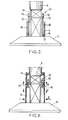
- Figure 2 shows the first segment 6 of the concrete structure 3 which, when the construction is finished, will be located at the top of the concrete structure 3.
- This segment 6 can be made by assembling several prefabricated concrete elements put into place using guide rails laid on the ground, or by casting concrete in a formwork arranged above the foundation 11 around the lower frame 13 of the support structure 10.
- brackets 16 are fixed to its inner face near the bottom part of the segment.
- Each bracket 16 has a horizontal abutment surface 17 for receiving the lower end of a hoisting cable 18.
- a number of brackets 16 (for example eight) are distributed along the circumference of the segment 6.
- Each hoisting cable 18, whose lower end bears against the abutment surface 17 of a bracket 16 extends beyond the platform 12 of the support structure 10 where it is held by a jack 19.
- Figure 3 also shows guide members 20 positioned between the inner face of the first segment 6 and the outer face of the cylindrical steel mast 4. These guide members 20 are fixed to the segment 6 and their innermost end may have a roller to bear against the mast 4.
- guide members 20 are distributed along the circumference of the segment 6 to guide and stabilize the concrete structure 3 while it is built. They can be fixed to the inside of the segment 6 by an operator standing on the platform 12 once the segment 6 has been sufficiently raised. Alternatively, their angular positions are offset with respect to those of the jacks 19 and they are fixed when the segment 6 is in the lower position shown in figure 2 .
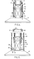
- next segment 6 With the first segment 6 in the lifted position shown in figure 3 , the next segment 6 can be assembled below it, for example by bringing concrete elements as indicated by the arrows B and bonding them together. When this next segment 6 is ready, the jacks 19 are progressively released to smoothly lay the previous segment 6 on its top surface as indicated by the arrows C. An adhesive can be placed at the interface between the two adjacent segments 6 in order to bond them if necessary.
- the jacks 19 are controlled to lower the hoisting cables 18, brackets 16 are fixed to the inner face of the segment 6 which was just assembled (possibly after having been dismantled from the previous segment), and the lower end of the hoisting cables 18 are respectively applied against the abutment surfaces 17 of the brackets 16. Then the jacks 19 are energized again to lift the two assembled segments 6 as indicated by the arrows D in figure 4 . During this lifting operation, the concrete structure 3 is suitably guided along the mast 4 by means of the guide members 20.
- prestressing cables can be mounted to strengthen the concrete structure 3, for example using the process described in the patent application No. EP 09306323.8 filed on December 23, 2009 .
- the steel mast is then lifted. Again, this lifting can be performed using the platform 12 of the support structure 10 and cable jacks. It is performed after disconnecting the lower frame 13 of the support structure 10 from the foundation 11.
- a ring-shaped plate 25 is placed at the top of the concrete structure 3.
- the plate 25 has a central hole to leave a passage for the steel mast 4 when it is lifted and openings regularly distributed along its periphery, but inside the wall of the concrete structure, to hold the upper ends of long hoisting cables 28 (about as long as the concrete structure is high).
- the lower ends of the long hoisting cables 28 are connected to respective jacks 29 bearing against the lower face of the platform 12.
- the jacks 29 are energized to raise the platform 12 and the elements secured to it, including the frames 13, 14 of the support structure 10 and the steel mast 4, as indicated by the arrows E in figure 5 .
- the concrete structure 3 which has been previously built and, if needed, prestressed is used as a support to guide and stabilize the mast 4.
- the guide members 20 located near the upper end of the concrete structure 3 can again participate in the guiding of the concrete structure 3 along the steel mast 4, as well as any additional guide members which may have been attached to the inner face of the concrete segments 6 during their erection.
- the critical phase is clearly the final phase in which the mast 4 reaches its final position above the concrete structure 3.
- the efficiency of the guiding is proportional to the vertical distance between the uppermost and lowermost bearing points, and that distance is minimal during the final phase in which, furthermore, the effects of the wind are maximum.
- the above-mentioned vertical distance is increased by using additional guide members 30 attached to the lower portion of the lower frame 13 of the support structure 10.
- Such guide members 30 are distributed around the periphery of the lower frame 13 in a star arrangement.
- Each of them has a fixed arm 31 attached to the lower frame 13, a movable arm 32 which can slide radially at the end of the fixed arm 31 remote from the lower frame 13, a roller 33 pivotally mounted about a horizontal axis at the end of the movable arm 32 and an actuator (not shown) to control the radial extension of the movable arm 32.
- the guide members 30 are fixed to the support structure 10 before activating the jacks 29 to lift the mast 4. At that time, the movable arms 32 are extended outwardly to be applied against the inner wall of the concrete structure 3. When the mast is raised, the position of the movable arms 32 is adjusted by means of the actuators to retract them progressively as the cross-section of the concrete structure 3 in front of the guide members 30 is reduced.
- the nacelle 5 of the wind generator 2 can be installed on top of the mast 4 after the telescoping operation. Alternatively, it is installed before extending the mast or once it has been extended partially. In this case, it is preferable if the center of gravity of the nacelle is aligned on or close to the central axis of the tower.
- Figure 6 illustrates the position of the mast 4 and the support structure 10 at the end of the lifting operation.
- the left-hand part of the figure shows an angular position at which there is a guide member 20 while the righthand part shows an angular position at which there is a hoisting cable 28 and the associated jack 29.
- the vertical distance H between the guide members 20 near the top of the concrete structure 3 and the guide members 30 at the bottom of the support structure 10 is significant, much larger than that h between the guide members 20 and the bottom part of the mast.
- the structure 10 is thus designed as a guiding structure which contributes to stabilizing the mast 4 before its final connection to the concrete structure 3.
- this guiding structure 10 is also used as a lifting support structure in the step of building the concrete structure 3 as discussed with reference to figures 2-4 .
- the structure 10 has a second, movable platform connected to the fixed platform 12 by the hoisting cables 18 and capable of sliding along vertical rails.
- the movable platform is applied against the bottom part of the segments 6 to lift them from underneath when assembling the concrete structure 3. Its lateral edges are fitted with the guide members 30 to be used in the step of lifting the steel mast 4.
- Various means can be used, alone or in combination, to connect the mast 4 to the concrete structure 3.
- steel beams can inserted horizontally in the region where the lower part of the mast 4 to the upper part of the concrete structure 3 overlap.
- first armatures on the steel mast 4 projecting outwardly at the lower part of the metal mast
- second armatures on the concrete structure 3 projecting inwardly from the uppermost segment 6, and to connect the lifted metal mast to the concrete structure by pouring cement or mortar in the interval where the first and second armatures extend and overlap.
- the guiding structure 10 can be disconnected from the bottom portion of the metal mast 4, and brought down to the foundation level using the cables 28 and the jacks 29.
- the guiding/support structure 10 can then be dismantled and taken out of the tower to be reused in the construction of another similar tower.
Landscapes
- Engineering & Computer Science (AREA)
- Architecture (AREA)
- Chemical & Material Sciences (AREA)
- Life Sciences & Earth Sciences (AREA)
- Civil Engineering (AREA)
- Structural Engineering (AREA)
- Materials Engineering (AREA)
- Wood Science & Technology (AREA)
- Sustainable Development (AREA)
- Sustainable Energy (AREA)
- Combustion & Propulsion (AREA)
- Mechanical Engineering (AREA)
- General Engineering & Computer Science (AREA)
- Wind Motors (AREA)
Priority Applications (10)
| Application Number | Priority Date | Filing Date | Title |
|---|---|---|---|
| ES10305351.8T ES2595231T3 (es) | 2010-04-06 | 2010-04-06 | Método de construcción de torre híbrida para un generador eólico |
| EP10305351.8A EP2374966B1 (de) | 2010-04-06 | 2010-04-06 | Verfahren zum Konstruieren eines Hybridturms für einen Windgenerator |
| DK10305351.8T DK2374966T3 (en) | 2010-04-06 | 2010-04-06 | A method of building a hybrid tower for a wind turbine |
| CA2735625A CA2735625C (en) | 2010-04-06 | 2011-03-31 | Method of building a hybrid tower for a wind generator |
| US13/079,309 US8297025B2 (en) | 2010-04-06 | 2011-04-04 | Method of building a hybrid tower for a wind generator |
| AU2011201502A AU2011201502B8 (en) | 2010-04-06 | 2011-04-04 | Method of building a hybrid tower for a wind generator |
| CN201110094498.9A CN102213033B (zh) | 2010-04-06 | 2011-04-06 | 风力发电机混合塔架的建造方法 |
| JP2011084388A JP5822509B2 (ja) | 2010-04-06 | 2011-04-06 | 風力発電機のためのハイブリッド型塔の建設方法 |
| KR1020110031655A KR101756323B1 (ko) | 2010-04-06 | 2011-04-06 | 풍력 발전기용 하이브리드 타워 건설방법 |
| BRPI1101612-4A BRPI1101612B1 (pt) | 2010-04-06 | 2011-04-06 | Método de construção de uma torre híbrida |
Applications Claiming Priority (1)
| Application Number | Priority Date | Filing Date | Title |
|---|---|---|---|
| EP10305351.8A EP2374966B1 (de) | 2010-04-06 | 2010-04-06 | Verfahren zum Konstruieren eines Hybridturms für einen Windgenerator |
Publications (2)
| Publication Number | Publication Date |
|---|---|
| EP2374966A1 true EP2374966A1 (de) | 2011-10-12 |
| EP2374966B1 EP2374966B1 (de) | 2016-07-20 |
Family
ID=43048929
Family Applications (1)
| Application Number | Title | Priority Date | Filing Date |
|---|---|---|---|
| EP10305351.8A Not-in-force EP2374966B1 (de) | 2010-04-06 | 2010-04-06 | Verfahren zum Konstruieren eines Hybridturms für einen Windgenerator |
Country Status (9)
| Country | Link |
|---|---|
| US (1) | US8297025B2 (de) |
| EP (1) | EP2374966B1 (de) |
| JP (1) | JP5822509B2 (de) |
| KR (1) | KR101756323B1 (de) |
| CN (1) | CN102213033B (de) |
| BR (1) | BRPI1101612B1 (de) |
| CA (1) | CA2735625C (de) |
| DK (1) | DK2374966T3 (de) |
| ES (1) | ES2595231T3 (de) |
Cited By (1)
| Publication number | Priority date | Publication date | Assignee | Title |
|---|---|---|---|---|
| WO2015177413A1 (fr) * | 2014-05-19 | 2015-11-26 | Soletanche Freyssinet | Système d'assemblage et procédé d'assemblage d'une tour pour aérogénérateur |
Families Citing this family (27)
| Publication number | Priority date | Publication date | Assignee | Title |
|---|---|---|---|---|
| KR20110128336A (ko) * | 2009-03-19 | 2011-11-29 | 텔레폰악티에볼라겟엘엠에릭슨(펍) | 전기통신타워 세그먼트 |
| DK2454427T3 (en) * | 2009-07-13 | 2017-05-15 | Vsl Int Ag | Telescopic tower arrangement and method |
| US8302365B2 (en) * | 2010-02-25 | 2012-11-06 | Gee Anthony F | Partially self-erecting wind turbine tower |
| ES2435211B2 (es) * | 2012-05-18 | 2014-12-12 | Structural Research, S.L. | Grúa telescópica autotrepante y procedimiento de montaje de torres prefabricadas de hormigón |
| CN103423099A (zh) * | 2012-05-21 | 2013-12-04 | 上海电气风能有限公司 | 一种可以用于大型陆上风力发电机组的混合塔架支撑结构 |
| JP5666517B2 (ja) * | 2012-07-12 | 2015-02-12 | 太平電業株式会社 | 塔状構造物の構築方法 |
| EP2711487B1 (de) | 2012-09-19 | 2015-09-09 | Alstom Technology Ltd | Konzentrierte Solarturmanordnung und Verfahren |
| CN104919177B (zh) * | 2012-11-15 | 2018-03-09 | 维斯塔斯风力系统有限公司 | 用于对准塔架区段的方法和装置 |
| DK2851490T3 (en) | 2013-09-20 | 2017-05-22 | Siemens Ag | Transport of a tower of a wind turbine |
| CN103726711B (zh) * | 2013-12-31 | 2016-04-20 | 国家电网公司 | 一种输电线路单体柱式抱杆 |
| CN107155336B (zh) * | 2014-01-31 | 2020-11-10 | 格雷戈里·约翰·内伯尔斯 | 混凝土塔和相关模架及相关构造方法 |
| CN106662068B (zh) * | 2014-04-01 | 2019-06-11 | 纳布拉风力技术公司 | 组装风轮机的系统和方法 |
| US9556636B2 (en) * | 2014-06-27 | 2017-01-31 | Tindall Corporation | Method and apparatus for erecting tower with hydraulic cylinders |
| DE102015003982A1 (de) * | 2015-03-26 | 2016-09-29 | Liebherr-Werk Biberach Gmbh | Kranturm |
| ES2606786B1 (es) * | 2015-09-23 | 2018-01-31 | Esteyco S.A.P. | Dispositivo de guiado para montaje de torres eólicas |
| DK3211154T3 (da) * | 2016-02-26 | 2022-05-02 | Nordex Energy Spain S A | Fremgangsmåde til fremstilling af betontårne til vindmøller |
| JP6937627B2 (ja) * | 2016-07-13 | 2021-09-22 | 戸田建設株式会社 | 洋上風力発電設備及びその施工方法 |
| CN107387337B (zh) * | 2017-09-01 | 2023-03-10 | 三一重能股份有限公司 | 风力发电机、底架及用于制备该底架的施工设备 |
| CN107697818B (zh) * | 2017-10-17 | 2023-10-17 | 郑州科润机电工程有限公司 | 一种预应力混凝土风电塔筒壁施工方法及专用施工设备 |
| CN108560992B (zh) * | 2018-03-14 | 2023-10-31 | 扬州市中润模板有限公司 | 高耸构筑物的施工设备及砼浇筑施工方法 |
| KR102124293B1 (ko) * | 2019-09-27 | 2020-06-17 | 신상봉 | 풍력 발전용 강관형 타워의 현장 시공 방법 및 이를 구현하기 위한 시스템 |
| JP7144471B2 (ja) * | 2020-03-10 | 2022-09-29 | 太平電業株式会社 | タワー部材の積み上げ方法及びタワー部材の積み上げ方法に用いられる吊り上げ用器具 |
| KR102374486B1 (ko) * | 2020-11-17 | 2022-03-16 | 주식회사케이베츠 | 리프팅 잭과 그리퍼를 이용한 외부관입형 해상 지지구조물 연결구조 및 연결방법 |
| KR102374485B1 (ko) * | 2020-11-17 | 2022-03-16 | 주식회사케이베츠 | 리프팅 잭과 그리퍼를 이용한 내부관입형 해상 지지구조물 연결구조 및 연결방법 |
| KR102323886B1 (ko) * | 2021-10-14 | 2021-11-09 | 호산엔지니어링(주) | 풍력발전설비용 텔레스코픽 타워 원격 조정 장치 |
| NO347712B1 (en) * | 2022-02-16 | 2024-02-26 | Tebina Energi As | A windmill construction and a method for assembly of a windmill construction |
| CN114576097B (zh) * | 2022-03-02 | 2023-09-19 | 武汉釜硕新能源科技有限公司 | 一种新型风力发电塔及其施工方法 |
Citations (4)
| Publication number | Priority date | Publication date | Assignee | Title |
|---|---|---|---|---|
| DE3718436A1 (de) * | 1987-06-02 | 1988-12-22 | Wolfgang Keuser | Verfahren zur herstellung von turmartigen bauwerken |
| JPH01190883A (ja) | 1988-01-27 | 1989-07-31 | Ohbayashi Corp | リフトアップまたはダウン工法 |
| DE10111280A1 (de) | 2001-03-09 | 2002-07-25 | Erwin Keller | Verfahren und Vorrichtung zur Erstellung einer Windkraftanlage |
| WO2007125138A1 (es) * | 2006-03-28 | 2007-11-08 | Gamesa Innovation & Technology, S.L. | Útil de izado para el montaje de un aerogenerador |
Family Cites Families (22)
| Publication number | Priority date | Publication date | Assignee | Title |
|---|---|---|---|---|
| US3673754A (en) * | 1969-07-18 | 1972-07-04 | Kawatetsu Kizai Kogyo Co | Lift up process |
| US5490364A (en) * | 1994-08-30 | 1996-02-13 | Dreco, Inc. | Telescopic flare pipe tower |
| JP2001140501A (ja) * | 1999-11-18 | 2001-05-22 | Taisei Corp | タワー状建築物の建方方法 |
| ATE279617T1 (de) | 2000-05-15 | 2004-10-15 | Rund Stahl Bau Gmbh & Co | Verfahren zur errichtung mehrerer gleichartiger bauwerke mit einer kegelstumpfförmigen form |
| DE10033845A1 (de) | 2000-07-12 | 2002-01-24 | Aloys Wobben | Turm aus Spannbeton-Fertigteilen |
| JP3648146B2 (ja) | 2000-10-16 | 2005-05-18 | 株式会社ピーエス三菱 | 風力発電タワー |
| US6782667B2 (en) | 2000-12-05 | 2004-08-31 | Z-Tek, Llc | Tilt-up and telescopic support tower for large structures |
| DE10126912A1 (de) | 2001-06-01 | 2002-12-19 | Oevermann Gmbh & Co Kg Hoch Un | Turmbauwerk aus Spannbeton |
| NL1019953C2 (nl) | 2002-02-12 | 2002-12-19 | Mecal Applied Mechanics B V | Geprefabriceerde toren of mast, alsmede een methode voor het samenvoegen en/of naspannen van segmenten die één constructie moeten vormen, alsmede een werkwijze voor het opbouwen van een toren of mast bestaande uit segmenten. |
| JP2003239567A (ja) | 2002-02-20 | 2003-08-27 | Tomoe Giken:Kk | 塔状構造物の構築方法 |
| US7966777B2 (en) * | 2004-06-25 | 2011-06-28 | Itt Manufacturing Enterprises, Inc. | Mechanical lift, fully nesting, telescoping mast |
| JP4652733B2 (ja) | 2004-07-06 | 2011-03-16 | 鹿島建設株式会社 | 風力発電装置の建設方法 |
| ES1058539Y (es) * | 2004-10-11 | 2005-04-01 | Inneo21 S L | Estructura perfeccionada de torre modular para turbinas eolicas y otras aplicaciones. |
| ES2246734B1 (es) | 2005-04-21 | 2007-04-16 | STRUCTURAL CONCRETE & STEEL, S.L. | Torre modular prefabricada. |
| JP4701047B2 (ja) * | 2005-09-07 | 2011-06-15 | 株式会社竹中工務店 | 風力発電タワーの構築方法 |
| US8056296B2 (en) * | 2006-04-07 | 2011-11-15 | General Electric Company | Methods and apparatus for assembling wind turbine towers |
| ES2326010B2 (es) | 2006-08-16 | 2011-02-18 | Inneo21, S.L. | Estructura y procedimiento de montaje de torres de hormigon para turbinas eolicas. |
| US8069634B2 (en) * | 2006-10-02 | 2011-12-06 | General Electric Company | Lifting system and apparatus for constructing and enclosing wind turbine towers |
| DE202007003842U1 (de) | 2007-03-15 | 2007-05-24 | Mecal Applied Mechanics B.V. | Mast für eine Windturbine |
| DE102007031065B4 (de) | 2007-06-28 | 2011-05-05 | Nordex Energy Gmbh | Windenergieanlagenturm |
| WO2009056898A1 (es) | 2007-11-02 | 2009-05-07 | Alejandro Cortina-Cordero | Torre de concreto postensado para generadores eolicos |
| US20090087311A1 (en) * | 2007-09-29 | 2009-04-02 | Gavin Raymond Wyborn | Vertically Adjustable Horizontal Axis Type Wind Turbine And Method Of Construction Thereof |
-
2010
- 2010-04-06 EP EP10305351.8A patent/EP2374966B1/de not_active Not-in-force
- 2010-04-06 DK DK10305351.8T patent/DK2374966T3/en active
- 2010-04-06 ES ES10305351.8T patent/ES2595231T3/es active Active
-
2011
- 2011-03-31 CA CA2735625A patent/CA2735625C/en not_active Expired - Fee Related
- 2011-04-04 US US13/079,309 patent/US8297025B2/en active Active
- 2011-04-06 JP JP2011084388A patent/JP5822509B2/ja not_active Expired - Fee Related
- 2011-04-06 KR KR1020110031655A patent/KR101756323B1/ko active IP Right Grant
- 2011-04-06 BR BRPI1101612-4A patent/BRPI1101612B1/pt not_active IP Right Cessation
- 2011-04-06 CN CN201110094498.9A patent/CN102213033B/zh not_active Expired - Fee Related
Patent Citations (5)
| Publication number | Priority date | Publication date | Assignee | Title |
|---|---|---|---|---|
| DE3718436A1 (de) * | 1987-06-02 | 1988-12-22 | Wolfgang Keuser | Verfahren zur herstellung von turmartigen bauwerken |
| JPH01190883A (ja) | 1988-01-27 | 1989-07-31 | Ohbayashi Corp | リフトアップまたはダウン工法 |
| DE10111280A1 (de) | 2001-03-09 | 2002-07-25 | Erwin Keller | Verfahren und Vorrichtung zur Erstellung einer Windkraftanlage |
| WO2007125138A1 (es) * | 2006-03-28 | 2007-11-08 | Gamesa Innovation & Technology, S.L. | Útil de izado para el montaje de un aerogenerador |
| US20100189531A1 (en) * | 2006-03-28 | 2010-07-29 | Gamesa Innovation & Technology, S.L. | Lifting device for the assembly of a wind turbine |
Cited By (2)
| Publication number | Priority date | Publication date | Assignee | Title |
|---|---|---|---|---|
| WO2015177413A1 (fr) * | 2014-05-19 | 2015-11-26 | Soletanche Freyssinet | Système d'assemblage et procédé d'assemblage d'une tour pour aérogénérateur |
| US10364800B2 (en) | 2014-05-19 | 2019-07-30 | Soletanche Freyssinet | Assembly system and method for assembling a tower for a wind generator |
Also Published As
| Publication number | Publication date |
|---|---|
| BRPI1101612B1 (pt) | 2020-06-16 |
| AU2011201502A1 (en) | 2011-10-20 |
| US8297025B2 (en) | 2012-10-30 |
| CN102213033A (zh) | 2011-10-12 |
| AU2011201502B2 (en) | 2016-04-28 |
| KR20110112228A (ko) | 2011-10-12 |
| EP2374966B1 (de) | 2016-07-20 |
| CN102213033B (zh) | 2016-07-13 |
| US20110239584A1 (en) | 2011-10-06 |
| JP5822509B2 (ja) | 2015-11-24 |
| KR101756323B1 (ko) | 2017-07-10 |
| JP2011220102A (ja) | 2011-11-04 |
| CA2735625A1 (en) | 2011-10-06 |
| ES2595231T3 (es) | 2016-12-28 |
| DK2374966T3 (en) | 2016-11-07 |
| CA2735625C (en) | 2018-02-20 |
Similar Documents
| Publication | Publication Date | Title |
|---|---|---|
| EP2374966B1 (de) | Verfahren zum Konstruieren eines Hybridturms für einen Windgenerator | |
| JP5629316B2 (ja) | 伸縮式タワーアセンブリおよび方法 | |
| US8281546B2 (en) | Slip formed concrete wind turbine tower | |
| EP2746571B1 (de) | Windturbinenanordungssystem | |
| EP3019433B1 (de) | Anordnung und verfahren zum heben von lasten | |
| EP2851328A1 (de) | Selbstkletternder teleskopkran und verfahren zur montage von fertigbaubetontürmen | |
| US9657495B2 (en) | Crane system incorporated into a tower | |
| US10815687B2 (en) | Wind turbine assembly system and associated method | |
| EP3314119B1 (de) | Verfahren zum errichten eines kabelgebundenen windturbinenturms | |
| US10738499B2 (en) | Concrete towers manufacturing method for wind turbines and concrete tower for wind turbine | |
| EP3786393B1 (de) | Bewegliches modul zum heben von teleskopischen türmen und verfahren zum heben von teleskopischen türmen | |
| JP4722630B2 (ja) | 塔状構造物の構築方法および同方法に使用されるスリップフォーム装置 | |
| EP2857615A1 (de) | Montageverfahren und Montagevorrichtung eines Betonturms aus vorgefertigten Teilen | |
| AU2011201502B8 (en) | Method of building a hybrid tower for a wind generator | |
| KR20140047791A (ko) | 풍력발전기 시공장치 및 방법 | |
| WO2013024203A1 (en) | Method and arrangement for erecting wind power plant |
Legal Events
| Date | Code | Title | Description |
|---|---|---|---|
| PUAI | Public reference made under article 153(3) epc to a published international application that has entered the european phase |
Free format text: ORIGINAL CODE: 0009012 |
|
| 17P | Request for examination filed |
Effective date: 20110726 |
|
| AK | Designated contracting states |
Kind code of ref document: A1 Designated state(s): AT BE BG CH CY CZ DE DK EE ES FI FR GB GR HR HU IE IS IT LI LT LU LV MC MK MT NL NO PL PT RO SE SI SK SM TR |
|
| AX | Request for extension of the european patent |
Extension state: AL BA ME RS |
|
| RAP1 | Party data changed (applicant data changed or rights of an application transferred) |
Owner name: SOLETANCHE FREYSSINET |
|
| GRAP | Despatch of communication of intention to grant a patent |
Free format text: ORIGINAL CODE: EPIDOSNIGR1 |
|
| INTG | Intention to grant announced |
Effective date: 20160104 |
|
| GRAS | Grant fee paid |
Free format text: ORIGINAL CODE: EPIDOSNIGR3 |
|
| GRAA | (expected) grant |
Free format text: ORIGINAL CODE: 0009210 |
|
| AK | Designated contracting states |
Kind code of ref document: B1 Designated state(s): AT BE BG CH CY CZ DE DK EE ES FI FR GB GR HR HU IE IS IT LI LT LU LV MC MK MT NL NO PL PT RO SE SI SK SM TR |
|
| REG | Reference to a national code |
Ref country code: GB Ref legal event code: FG4D |
|
| RIC1 | Information provided on ipc code assigned before grant |
Ipc: F03D 13/20 20160101ALI20160615BHEP Ipc: E04H 12/08 20060101ALI20160615BHEP Ipc: E04H 12/12 20060101ALI20160615BHEP Ipc: E04H 12/02 20060101AFI20160615BHEP Ipc: F03D 1/00 20060101ALI20160615BHEP Ipc: E04H 12/34 20060101ALI20160615BHEP |
|
| REG | Reference to a national code |
Ref country code: CH Ref legal event code: EP |
|
| REG | Reference to a national code |
Ref country code: IE Ref legal event code: FG4D |
|
| REG | Reference to a national code |
Ref country code: AT Ref legal event code: REF Ref document number: 814238 Country of ref document: AT Kind code of ref document: T Effective date: 20160815 |
|
| REG | Reference to a national code |
Ref country code: DE Ref legal event code: R096 Ref document number: 602010034814 Country of ref document: DE |
|
| REG | Reference to a national code |
Ref country code: DK Ref legal event code: T3 Effective date: 20161031 |
|
| REG | Reference to a national code |
Ref country code: LT Ref legal event code: MG4D |
|
| REG | Reference to a national code |
Ref country code: NL Ref legal event code: MP Effective date: 20160720 |
|
| REG | Reference to a national code |
Ref country code: AT Ref legal event code: MK05 Ref document number: 814238 Country of ref document: AT Kind code of ref document: T Effective date: 20160720 |
|
| REG | Reference to a national code |
Ref country code: ES Ref legal event code: FG2A Ref document number: 2595231 Country of ref document: ES Kind code of ref document: T3 Effective date: 20161228 |
|
| PG25 | Lapsed in a contracting state [announced via postgrant information from national office to epo] |
Ref country code: FI Free format text: LAPSE BECAUSE OF FAILURE TO SUBMIT A TRANSLATION OF THE DESCRIPTION OR TO PAY THE FEE WITHIN THE PRESCRIBED TIME-LIMIT Effective date: 20160720 Ref country code: HR Free format text: LAPSE BECAUSE OF FAILURE TO SUBMIT A TRANSLATION OF THE DESCRIPTION OR TO PAY THE FEE WITHIN THE PRESCRIBED TIME-LIMIT Effective date: 20160720 Ref country code: IS Free format text: LAPSE BECAUSE OF FAILURE TO SUBMIT A TRANSLATION OF THE DESCRIPTION OR TO PAY THE FEE WITHIN THE PRESCRIBED TIME-LIMIT Effective date: 20161120 Ref country code: NO Free format text: LAPSE BECAUSE OF FAILURE TO SUBMIT A TRANSLATION OF THE DESCRIPTION OR TO PAY THE FEE WITHIN THE PRESCRIBED TIME-LIMIT Effective date: 20161020 Ref country code: LT Free format text: LAPSE BECAUSE OF FAILURE TO SUBMIT A TRANSLATION OF THE DESCRIPTION OR TO PAY THE FEE WITHIN THE PRESCRIBED TIME-LIMIT Effective date: 20160720 Ref country code: IT Free format text: LAPSE BECAUSE OF FAILURE TO SUBMIT A TRANSLATION OF THE DESCRIPTION OR TO PAY THE FEE WITHIN THE PRESCRIBED TIME-LIMIT Effective date: 20160720 Ref country code: NL Free format text: LAPSE BECAUSE OF FAILURE TO SUBMIT A TRANSLATION OF THE DESCRIPTION OR TO PAY THE FEE WITHIN THE PRESCRIBED TIME-LIMIT Effective date: 20160720 |
|
| PG25 | Lapsed in a contracting state [announced via postgrant information from national office to epo] |
Ref country code: GR Free format text: LAPSE BECAUSE OF FAILURE TO SUBMIT A TRANSLATION OF THE DESCRIPTION OR TO PAY THE FEE WITHIN THE PRESCRIBED TIME-LIMIT Effective date: 20161021 Ref country code: BE Free format text: LAPSE BECAUSE OF FAILURE TO SUBMIT A TRANSLATION OF THE DESCRIPTION OR TO PAY THE FEE WITHIN THE PRESCRIBED TIME-LIMIT Effective date: 20160720 Ref country code: PL Free format text: LAPSE BECAUSE OF FAILURE TO SUBMIT A TRANSLATION OF THE DESCRIPTION OR TO PAY THE FEE WITHIN THE PRESCRIBED TIME-LIMIT Effective date: 20160720 Ref country code: AT Free format text: LAPSE BECAUSE OF FAILURE TO SUBMIT A TRANSLATION OF THE DESCRIPTION OR TO PAY THE FEE WITHIN THE PRESCRIBED TIME-LIMIT Effective date: 20160720 Ref country code: SE Free format text: LAPSE BECAUSE OF FAILURE TO SUBMIT A TRANSLATION OF THE DESCRIPTION OR TO PAY THE FEE WITHIN THE PRESCRIBED TIME-LIMIT Effective date: 20160720 Ref country code: LV Free format text: LAPSE BECAUSE OF FAILURE TO SUBMIT A TRANSLATION OF THE DESCRIPTION OR TO PAY THE FEE WITHIN THE PRESCRIBED TIME-LIMIT Effective date: 20160720 Ref country code: PT Free format text: LAPSE BECAUSE OF FAILURE TO SUBMIT A TRANSLATION OF THE DESCRIPTION OR TO PAY THE FEE WITHIN THE PRESCRIBED TIME-LIMIT Effective date: 20161121 |
|
| REG | Reference to a national code |
Ref country code: FR Ref legal event code: PLFP Year of fee payment: 8 |
|
| REG | Reference to a national code |
Ref country code: DE Ref legal event code: R097 Ref document number: 602010034814 Country of ref document: DE |
|
| PG25 | Lapsed in a contracting state [announced via postgrant information from national office to epo] |
Ref country code: RO Free format text: LAPSE BECAUSE OF FAILURE TO SUBMIT A TRANSLATION OF THE DESCRIPTION OR TO PAY THE FEE WITHIN THE PRESCRIBED TIME-LIMIT Effective date: 20160720 Ref country code: EE Free format text: LAPSE BECAUSE OF FAILURE TO SUBMIT A TRANSLATION OF THE DESCRIPTION OR TO PAY THE FEE WITHIN THE PRESCRIBED TIME-LIMIT Effective date: 20160720 |
|
| PLBE | No opposition filed within time limit |
Free format text: ORIGINAL CODE: 0009261 |
|
| STAA | Information on the status of an ep patent application or granted ep patent |
Free format text: STATUS: NO OPPOSITION FILED WITHIN TIME LIMIT |
|
| PG25 | Lapsed in a contracting state [announced via postgrant information from national office to epo] |
Ref country code: SK Free format text: LAPSE BECAUSE OF FAILURE TO SUBMIT A TRANSLATION OF THE DESCRIPTION OR TO PAY THE FEE WITHIN THE PRESCRIBED TIME-LIMIT Effective date: 20160720 Ref country code: CZ Free format text: LAPSE BECAUSE OF FAILURE TO SUBMIT A TRANSLATION OF THE DESCRIPTION OR TO PAY THE FEE WITHIN THE PRESCRIBED TIME-LIMIT Effective date: 20160720 Ref country code: BG Free format text: LAPSE BECAUSE OF FAILURE TO SUBMIT A TRANSLATION OF THE DESCRIPTION OR TO PAY THE FEE WITHIN THE PRESCRIBED TIME-LIMIT Effective date: 20161020 Ref country code: SM Free format text: LAPSE BECAUSE OF FAILURE TO SUBMIT A TRANSLATION OF THE DESCRIPTION OR TO PAY THE FEE WITHIN THE PRESCRIBED TIME-LIMIT Effective date: 20160720 |
|
| 26N | No opposition filed |
Effective date: 20170421 |
|
| PG25 | Lapsed in a contracting state [announced via postgrant information from national office to epo] |
Ref country code: SI Free format text: LAPSE BECAUSE OF FAILURE TO SUBMIT A TRANSLATION OF THE DESCRIPTION OR TO PAY THE FEE WITHIN THE PRESCRIBED TIME-LIMIT Effective date: 20160720 |
|
| REG | Reference to a national code |
Ref country code: CH Ref legal event code: PL |
|
| REG | Reference to a national code |
Ref country code: IE Ref legal event code: MM4A |
|
| PG25 | Lapsed in a contracting state [announced via postgrant information from national office to epo] |
Ref country code: MC Free format text: LAPSE BECAUSE OF FAILURE TO SUBMIT A TRANSLATION OF THE DESCRIPTION OR TO PAY THE FEE WITHIN THE PRESCRIBED TIME-LIMIT Effective date: 20160720 |
|
| PG25 | Lapsed in a contracting state [announced via postgrant information from national office to epo] |
Ref country code: CH Free format text: LAPSE BECAUSE OF NON-PAYMENT OF DUE FEES Effective date: 20170430 Ref country code: LI Free format text: LAPSE BECAUSE OF NON-PAYMENT OF DUE FEES Effective date: 20170430 Ref country code: LU Free format text: LAPSE BECAUSE OF NON-PAYMENT OF DUE FEES Effective date: 20170406 |
|
| REG | Reference to a national code |
Ref country code: FR Ref legal event code: PLFP Year of fee payment: 9 |
|
| PG25 | Lapsed in a contracting state [announced via postgrant information from national office to epo] |
Ref country code: IE Free format text: LAPSE BECAUSE OF NON-PAYMENT OF DUE FEES Effective date: 20170406 |
|
| PG25 | Lapsed in a contracting state [announced via postgrant information from national office to epo] |
Ref country code: MT Free format text: LAPSE BECAUSE OF NON-PAYMENT OF DUE FEES Effective date: 20170406 |
|
| PG25 | Lapsed in a contracting state [announced via postgrant information from national office to epo] |
Ref country code: HU Free format text: LAPSE BECAUSE OF FAILURE TO SUBMIT A TRANSLATION OF THE DESCRIPTION OR TO PAY THE FEE WITHIN THE PRESCRIBED TIME-LIMIT; INVALID AB INITIO Effective date: 20100406 |
|
| PG25 | Lapsed in a contracting state [announced via postgrant information from national office to epo] |
Ref country code: CY Free format text: LAPSE BECAUSE OF NON-PAYMENT OF DUE FEES Effective date: 20160720 |
|
| PG25 | Lapsed in a contracting state [announced via postgrant information from national office to epo] |
Ref country code: MK Free format text: LAPSE BECAUSE OF FAILURE TO SUBMIT A TRANSLATION OF THE DESCRIPTION OR TO PAY THE FEE WITHIN THE PRESCRIBED TIME-LIMIT Effective date: 20160720 |
|
| PG25 | Lapsed in a contracting state [announced via postgrant information from national office to epo] |
Ref country code: TR Free format text: LAPSE BECAUSE OF FAILURE TO SUBMIT A TRANSLATION OF THE DESCRIPTION OR TO PAY THE FEE WITHIN THE PRESCRIBED TIME-LIMIT Effective date: 20160720 |
|
| PGFP | Annual fee paid to national office [announced via postgrant information from national office to epo] |
Ref country code: GB Payment date: 20200323 Year of fee payment: 11 Ref country code: DK Payment date: 20200325 Year of fee payment: 11 |
|
| PGFP | Annual fee paid to national office [announced via postgrant information from national office to epo] |
Ref country code: FR Payment date: 20200319 Year of fee payment: 11 |
|
| PGFP | Annual fee paid to national office [announced via postgrant information from national office to epo] |
Ref country code: DE Payment date: 20200319 Year of fee payment: 11 Ref country code: ES Payment date: 20200504 Year of fee payment: 11 |
|
| REG | Reference to a national code |
Ref country code: DE Ref legal event code: R119 Ref document number: 602010034814 Country of ref document: DE |
|
| REG | Reference to a national code |
Ref country code: DK Ref legal event code: EBP Effective date: 20210430 |
|
| GBPC | Gb: european patent ceased through non-payment of renewal fee |
Effective date: 20210406 |
|
| PG25 | Lapsed in a contracting state [announced via postgrant information from national office to epo] |
Ref country code: DE Free format text: LAPSE BECAUSE OF NON-PAYMENT OF DUE FEES Effective date: 20211103 Ref country code: FR Free format text: LAPSE BECAUSE OF NON-PAYMENT OF DUE FEES Effective date: 20210430 Ref country code: GB Free format text: LAPSE BECAUSE OF NON-PAYMENT OF DUE FEES Effective date: 20210406 |
|
| PG25 | Lapsed in a contracting state [announced via postgrant information from national office to epo] |
Ref country code: DK Free format text: LAPSE BECAUSE OF NON-PAYMENT OF DUE FEES Effective date: 20210430 |
|
| REG | Reference to a national code |
Ref country code: ES Ref legal event code: FD2A Effective date: 20220630 |
|
| PG25 | Lapsed in a contracting state [announced via postgrant information from national office to epo] |
Ref country code: ES Free format text: LAPSE BECAUSE OF NON-PAYMENT OF DUE FEES Effective date: 20210407 |