EP2374748B1 - Mehrstufiger Wagen für einen Kran und Kran damit - Google Patents
Mehrstufiger Wagen für einen Kran und Kran damit Download PDFInfo
- Publication number
- EP2374748B1 EP2374748B1 EP10194823A EP10194823A EP2374748B1 EP 2374748 B1 EP2374748 B1 EP 2374748B1 EP 10194823 A EP10194823 A EP 10194823A EP 10194823 A EP10194823 A EP 10194823A EP 2374748 B1 EP2374748 B1 EP 2374748B1
- Authority
- EP
- European Patent Office
- Prior art keywords
- trolley
- hoisting wire
- stage
- spreader
- crane
- Prior art date
- Legal status (The legal status is an assumption and is not a legal conclusion. Google has not performed a legal analysis and makes no representation as to the accuracy of the status listed.)
- Not-in-force
Links
- 238000010276 construction Methods 0.000 description 4
- 238000007667 floating Methods 0.000 description 4
- 238000005096 rolling process Methods 0.000 description 4
- 238000000034 method Methods 0.000 description 2
- 238000004804 winding Methods 0.000 description 2
- 238000005452 bending Methods 0.000 description 1
- 230000007547 defect Effects 0.000 description 1
- 238000012986 modification Methods 0.000 description 1
- 230000004048 modification Effects 0.000 description 1
- 238000011017 operating method Methods 0.000 description 1
- 238000011160 research Methods 0.000 description 1
- XLYOFNOQVPJJNP-UHFFFAOYSA-N water Substances O XLYOFNOQVPJJNP-UHFFFAOYSA-N 0.000 description 1
Images


Classifications
-
- B—PERFORMING OPERATIONS; TRANSPORTING
- B66—HOISTING; LIFTING; HAULING
- B66C—CRANES; LOAD-ENGAGING ELEMENTS OR DEVICES FOR CRANES, CAPSTANS, WINCHES, OR TACKLES
- B66C19/00—Cranes comprising trolleys or crabs running on fixed or movable bridges or gantries
- B66C19/002—Container cranes
Definitions
- the present invention relates to a trolley and a crane for loading and unloading a cargo.
- a marine transportation using ships as a goods movement means to a remote area consumes less energy compared with other transportation and incurs a low transportation cost, so it takes a large portion of global trade.
- a marine transportation such as a container carrier uses a large ship in order to improve the efficiency of transportation, and the use of the large ship increases the volume of traffic of ships to secure economic efficiency of transportation.
- more harbors having mooring facilities for allowing a large ship to come alongside the pier and loading and unloading facilities are increasingly required.
- Fig. 1 is a schematic view showing that a container C handling operation with respect to a container carrier S is performed by a crane 1 installed in a ship 50 serving as a mobile harbor.
- a widthwise direction of a boom 10 (or a lengthwise direction of the ship 50) is defined as a lateral direction (X direction in the figure)
- a lengthwise direction of the boom 10 (or a widthwise direction of the ship 50) is defined as a longitudinal direction (Y direction in the figure).
- the crane 10 comprises a spreader 30 gripping a container C and moved in the vertical direction, a trolley 20 supporting the spreader 30 and moved in the longitudinal direction and the boom 10 guiding the trolley 20 to enable the trolley to be moved, such a crane is known from document US 2008/0213073 .
- Fig. 2 is a view showing schematically a method for tying a hoist wire of a conventional crane.
- a spreader is moved in the vertical direction by using a hoist wire system provided on a boom B.
- the hoist wire system includes a wire drum B1 winding/unwinding a hoist wire W and a various kinds of sheave blocks B2, B3, T1 and S1 for changing a direction of the hoist wire W.
- a spreader is coupled to the sheave block S1.
- the hoist wire W is tied such that a vertical level of the spreader is not changed even though a trolley T is moved.
- a pitching and a rolling of the ship on the sea are indispensably occurred due to a wind, wave or tidal current, and the like.
- the trolley 20 moved on the crane boom 10 and the spreader 30 mounted to the trolley can be moved only the longitudinal direction. Accordingly, when a relative location between the crane 1 or the ship 50 and the container ship S is not maintained due to a pitching and rolling of the ship, it is difficult to couple or decouple the spreader 30 with or from the container. To correct the above defect, the crane 1 itself or the ship 50 itself should be moved, so that it is not easy to control the crane or the ship and power is excessively consumed.
- the present invention provides a multi-stage trolley for a crane in which a spreader can be moved in the lateral direction as well as the longitudinal direction, and a vertical level of the spreader can be maintained constant in spite of the above movement.
- a multi-stage trolley for a crane comprising: a first trolley movable in a longitudinal direction along a boom of the crane; a second trolley movable in a lateral direction on the first trolley; a hoisting wire provided in the longitudinal direction along the boom; a spreader connected to the hoisting wire through the first trolley and the second trolley and supported by the hoisting wire, the spreader being movable in a vertical direction according to a movement of the hoisting wire; and a sheave block unit for changing a direction of the hoisting wire to maintain a vertical level of the spreader constant when the first trolley and/or the second trolley is moved.
- a crane including the multi-stage trolley.
- a multi-stage trolley for a crane according to one embodiment of the present invention is illustrated with reference to Fig. 3 to Fig. 5
- Fig. 3 is a view showing schematically a multi-stage trolley and a hoisting wire system employed in a crane according to one embodiment of the present invention
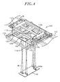
- Fig. 4 is a view showing schematically a structure of the multi-stage trolley according to one embodiment of the present invention
- Fig. 5 is a view showing schematically structure of the hoisting wire system with a sheave block unit according to one embodiment of the present invention.
- the crane according to one embodiment of the present invention is provided with a hoisting wire system which have a multi-stage trolley structure by which a spreader can be moved in the lateral and/or the longitudinal directions and vertical level of the spreader can be maintained regardless of the above movement.
- the multi-stage trolley comprises a first trolley 112, a second trolley 122, a third trolley 132, a spreader 140, a hoisting wire W, a wire driving drum 110a and a sheave block unit.
- FIG. 3 A structure and function of a multi-stage trolley is illustrated with reference to Fig. 3 and Fig. 4 .
- the first trolley 112 may be moved in the longitudinal direction along a boom 110.
- the second trolley 122 may be moved on the first trolley 112 in the lateral direction.
- the third trolley 132 may be moved on the second trolley 122 in the longitudinal direction.
- the first trolley 112 In order to move the spreader 140 in the lateral direction for transporting the container, the first trolley 112 is utilized, and the third trolley 132 can be moved in the lateral direction to correct a change of location caused by a pitching/rolling of the ship of the ship. Therefore, it is possible to operate rapidly and economically the spreader 140.
- the spreader 140 is connected to the hoisting wire W through the first, second and third trolleys 112, 122 and 132 and then supported by the hoisting wire W.
- the spreader 140 can be moved in the vertical direction according to a movement of the hosting wire W.
- the hosting wires W are provided at both lateral end portions of the boom 110 and arranged in the longitudinal direction so that the hoisting wire may be connected to spreader 140.
- the hosting wire W is passed through boom end sheave blocks 110b and 110c and extended from the wire driving drum 110a to the spreader 140 through the first, second and third trolleys 112, 122 and 132.
- the wire driving drum 110a winds or unwinds the hoisting wire W to adjust a vertical level of the spreader 140.
- a vertical movement of the spreader 140 is independently controlled by the wire driving drum 110a regardless of a movement of the trolley.
- the sheave blocks change a direction of the hoisting wire to allow a vertical level of the spreader 140 to be kept unchanged when the second trolley 122 is moved in the lateral direction. Also, the sheave blocks can compel the level of the spreader 140 to be unchanged when the third trolley 132 is moved in the longitudinal direction.
- a connection relation among the sheave blocks, the multi-stage trolley and the hoisting wire is illustrated in more detail with reference to Fig. 4 and Fig. 5 .
- the sheave block unit may include direction changing sheave blocks 112a and 112b, direction reversing sheave blocks 112c, direction restoring sheave blocks 122a, spreader sheave blocks 132a and 140a.
- Direction changing sheave blocks 112a and 112b change direction of the hoisting wire W provided in the longitudinal direction into the lateral direction. 2 or 4 pairs of direction changing sheave blocks 112a and 112b may be provided at longitudinal ends of the first trolley 112. Pairs of direction changing sheave blocks 112a and 112b diagonally disposed are coupled to each other by the hoisting wire.
- Direction reversing sheave blocks 112c change direction of the hoisting wire W by 180 degree, which is provided to the first trolley 112 in the lateral direction, by bending the hoisting wire into a U shape to connect the hoisting wire to the second trolley 122.
- 2 or 4 pairs of direction reversing sheave blocks 112c may be provided at lateral and longitudinal ends of the first trolley 112. Pairs of direction reversing sheave blocks 112c diagonally disposed are coupled to each other by the hoisting wire.
- Direction restoring sheave blocks 122a change direction of the hoisting wire W, which is provided to the second trolley 122 in the lateral direction, into the longitudinal direction to connect the hoisting wire to the third trolley 132. 2 or 4 pairs of direction restoring sheave blocks 122a may be provided. Pairs of direction restoring sheave blocks 122a diagonally disposed are coupled to each other by the hoisting wire.
- Spreader sheave blocks 132a change direction of the hoisting wire W, which is provided to the third trolley 132 in the longitudinal direction, into the vertical direction to connect the hoisting wire to spreader sheave blocks 140a provided on the spreader 140. 1 or 2 pairs of) third trolley sheave blocks 132a may be provided.
- the sheave blocks 112a, 112b, 112c, 122a located on the diagonal position are connected each other through the hoisting wire W via the spreader sheave blocks 140a.
- the third trolley 132 may not be provided in another embodiment of the present invention. Although the above structure in which the third trolley is not provided is not shown in the drawings, instead of the third trolley sheave blocks 132a, direction of the hoisting wire W may be changed into the vertical direction by sheave blocks provided on the second trolley 122, and so the hoisting wire can be connected to the spreader 140.
- Fig. 6 is a view showing a shape of the multi-stage trolley in a case where the first trolley is moved along the boom;
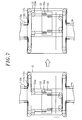
- Fig. 7 is a view showing a shape of the multi-stage trolley in a case where the second trolley is moved
- Fig. 8 is a view showing a shape of the hoisting wire in a case where the second trolley is moved.
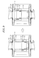
- Fig. 9 is a view showing a shape of the multi-stage in a case where the third trolley is moved
- Fig. 10 is a view showing a shape of the hoisting wire in a case where the third trolley is moved.
- the third trolley 132 is moved, the hoisting wire W out of the second trolley sheave blocks 122a is fixed.
- the third trolley 132 is moved in the lateral direction and a height of the spreader 140 is constantly maintained without a change of the length of the hoisting wire W in the third trolley sheave blocks 132a.
- Fig. 11 is a view showing a shape of the hoisting wire in a case where the spreader is moved.
- the hoisting wire W is wound or unwound by the wire driving drum 110a, and the spreader 140 is moved upward and downward according a winding or unwinding of the hoisting wire W.
- the crane with a multi-stage trolley may be provided on a floating body floated on the sea.
- the floating body may be a ship which is equipped with a self-power generating means and can be sailed, or a floating construction to be moored on the sea.
- the floating body can act as a mobile harbor which is floated on the sea and transfers a container between the container ships instead of a harbor of the land or together with a harbor of the land and stores temporarily the containers.
- the mobile harbor may include a platform having a space in which the container is loaded, a location determining device for acquiring information regarding the location of the platform, a mooring device for maintaining a connected state without colliding with the container carrier while a container is loaded or unloaded, and a balancing device for adjusting the platform such that the platform can be maintained in a vertical location correspondingly to a change in the weight based on the loading and unloading of the container.
- the spreader is moved in the longitudinal direction as well as the lateral direction on the trolley having the multi-stage trolley structure, and a vertical level of the spreader can be maintained or easily controlled.
Landscapes
- Engineering & Computer Science (AREA)
- Mechanical Engineering (AREA)
- Control And Safety Of Cranes (AREA)
- Carriers, Traveling Bodies, And Overhead Traveling Cranes (AREA)
Claims (10)
- Mehrstufiger Wagen für einen Kran mit:einem ersten Wagen (112), der in einer Längsrichtung entlang eines Auslegers (110) des Krans bewegbar ist;einem zweiten Wagen (122), der in einer lateralen Richtung auf dem ersten Wagen bewegbar ist;einem Förderseil (W), das in der Längsrichtung entlang des Auslegers (110) vorgesehen ist,gekennzeichnet durchein Containergeschirr (140), das mit dem Förderseil (W) über den ersten Wagen (112) und den zweiten Wagen (122) verbunden ist und vom Förderseil getragen wird, wobei das Containergeschirr (140) in einer vertikalen Richtung entsprechend einer Bewegung des Förderseils (W) bewegbar ist; undeine Seilrollenblockeinheit zum Ändern einer Richtung des Förderseils, wodurch ein vertikales Niveau des Containergeschirrs (140) konstant gehalten wird, wenn der erste Wagen (112) und/oder der zweite Wagen (122) bewegt wird.
- Mehrstufiger Wagen nach Patentanspruch 1, wobei die Seilrollenblockeinheit Richtungsänderungs-Seilrollenblöcke aufweist, wobei zumindest einer davon eine Richtungsänderung des zugeführten Förderseils von einer Längsrichtung in eine laterale Richtung durchführt.
- Mehrstufiger Wagen nach Patentanspruch 2, wobei die Richtungsänderungs-Seilrollenblöcke Paare von Richtungsänderungs-Seilrollenblöcken aufweisen, welche diagonal am ersten Wagen angeordnet sind, und
zumindest ein Paar der Richtungsänderungs-Seilrollenblöcke durch das Förderseil miteinander gekoppelt ist. - Mehrstufiger Wagen nach Patentanspruch 2 oder 3, wobei zumindest einer der Richtungsänderungs-Seilrollenblöcke die Richtung des in Längsrichtung zugeführten Förderseils in die vertikale Richtung und dann in die laterale Richtung ändert.
- Mehrstufiger Wagen nach einem der Patentansprüche 1 bis 4, wobei die Seilrollenblockeinheit Richtungsumkehr-Seilrollenblöcke aufweist, wobei zumindest einer davon eine Richtungsänderung des in Längsrichtung zugeführten Förderseils um 180 Grad durchführt, wodurch dasselbe mit dem zweiten Wagen (122) verbunden wird.
- Mehrstufiger Wagen nach Patentanspruch 5, wobei die Richtungsumkehr-Seilrollenblöcke Paare von Richtungsumkehr-Seilrollenblöcken aufweisen, welche diagonal am ersten Wagen angeordnet sind, und
zumindest ein Paar der Richtungsumkehr-Seilrollenblöcke durch das Förderseil (W) miteinander gekoppelt ist. - Mehrstufiger Wagen nach Patentanspruch 6, wobei die Paare der Richtungsumkehr-Seilrollenblöcke an den lateralen Enden des ersten Wagens (112) angeordnet sind.
- Mehrstufiger Wagen nach einem der Patentansprüche 1 bis 7, ferner aufweisend einen dritten Wagen (132), welcher in der Längsrichtung auf dem zweiten Wagen bewegbar ist,
wobei die Seilrollenblockeinheit das vertikale Niveau des Containergeschirrs konstant hält, wenn der dritte Wagen (132) bewegt wird. - Mehrstufiger Wagen nach Patentanspruch 8, wobei die Seilrollenblockeinheit Richtungswiederherstellungs-Seilrollenblöcke aufweist, welche auf dem zweiten Wagen (122) vorgesehen sind,
wobei zumindest einer davon eine Richtung des in lateraler Richtung zugeführten Förderseils in eine Längsrichtung ändert, wodurch dasselbe mit dem dritten Wagen (132) verbunden wird. - Kran mit einem mehrstufigen Wagen nach einem der Patentansprüche 1 bis 7.
Applications Claiming Priority (1)
| Application Number | Priority Date | Filing Date | Title |
|---|---|---|---|
| KR1020100032270A KR101112156B1 (ko) | 2010-04-08 | 2010-04-08 | 다단 트롤리 컨테이너 크레인 |
Publications (2)
| Publication Number | Publication Date |
|---|---|
| EP2374748A1 EP2374748A1 (de) | 2011-10-12 |
| EP2374748B1 true EP2374748B1 (de) | 2012-11-21 |
Family
ID=44212204
Family Applications (1)
| Application Number | Title | Priority Date | Filing Date |
|---|---|---|---|
| EP10194823A Not-in-force EP2374748B1 (de) | 2010-04-08 | 2010-12-14 | Mehrstufiger Wagen für einen Kran und Kran damit |
Country Status (5)
| Country | Link |
|---|---|
| US (1) | US8708172B2 (de) |
| EP (1) | EP2374748B1 (de) |
| KR (1) | KR101112156B1 (de) |
| CN (1) | CN102211740A (de) |
| WO (1) | WO2011126201A1 (de) |
Families Citing this family (11)
| Publication number | Priority date | Publication date | Assignee | Title |
|---|---|---|---|---|
| FI124474B (fi) * | 2013-03-01 | 2014-09-15 | Konecranes Oyj | Nostoköysijärjestely nosturin nostovaunussa |
| US8905702B1 (en) * | 2013-03-05 | 2014-12-09 | Inland Pipe Rehabilitation, Llc | Cable-driven trailer loading system for liner |
| EP3584211B1 (de) * | 2017-03-31 | 2024-05-22 | Hirata Corporation | Fördervorrichtung |
| KR102220458B1 (ko) * | 2019-04-01 | 2021-02-26 | (주)엔키아 | 권양장치에 설치되는 와이어 진단 장치 |
| CN110407087B (zh) * | 2019-08-26 | 2024-12-17 | 上海振华重工(集团)股份有限公司 | 岸边集装箱起重机大梁的加长装置及其加长方法 |
| KR102385064B1 (ko) | 2020-07-16 | 2022-04-11 | 현대삼호중공업 주식회사 | 크레인용 호이스트 장치 |
| KR102437147B1 (ko) | 2020-07-24 | 2022-08-26 | 현대인프라솔루션 주식회사 | 컨테이너 크레인 |
| CN112061985A (zh) * | 2020-09-30 | 2020-12-11 | 上海振华重工(集团)股份有限公司 | 一种双卷筒防摇门架小车系统 |
| KR20230144433A (ko) | 2022-04-07 | 2023-10-16 | 노갑문 | 스마트하고 에너지절감형의 컨테이너 크레인 시스템 |
| KR20230158811A (ko) | 2022-05-12 | 2023-11-21 | 남해호이스트 주식회사 | 크레인용 호이스트 장치 |
| US12398532B2 (en) * | 2024-01-19 | 2025-08-26 | Wing Marine Llc | Marine vessels and methods of using same |
Family Cites Families (32)
| Publication number | Priority date | Publication date | Assignee | Title |
|---|---|---|---|---|
| US3081884A (en) * | 1961-06-09 | 1963-03-19 | Manning Maxwell & Moore Inc | Crane with anti-sway mechanism |
| US3207329A (en) * | 1962-12-03 | 1965-09-21 | Lake Shore Inc | Cargo handling apparatus |
| GB1162878A (en) * | 1967-06-09 | 1969-08-27 | John Stevenson Thomson | Improvements relating to Cranes for Handling Containers |
| US3536351A (en) * | 1967-11-13 | 1970-10-27 | Fruehauf Corp | Apparatus for simultaneously lifting and spacing cargo containers |
| US3671069A (en) * | 1970-07-15 | 1972-06-20 | Fruehaul Corp | Cargo container lifting and spacing apparatus |
| US3945503A (en) * | 1970-10-02 | 1976-03-23 | Fruehauf Corporation | Crane with a variable center rope suspension system |
| IT981544B (it) * | 1972-03-24 | 1974-10-10 | Krupp Gmbh | Dispositivo per smorzare oscillazioni |
| US3779395A (en) * | 1972-11-15 | 1973-12-18 | Heyl & Patterson | Clamshell bucket unloader with rope operated trolley |
| AU471953B2 (en) * | 1972-12-29 | 1976-05-06 | Ishikawajima-Harima Jukogyo K.K. | Device for preventing the swaying ofthe suspending means ina crane |
| US3887080A (en) * | 1973-06-29 | 1975-06-03 | Ray Wilson | Crane structure |
| US3944272A (en) * | 1974-08-12 | 1976-03-16 | Midland-Ross Corporation | Cargo container spreader with articulated structure for skewing and tilting |
| NL7614540A (nl) * | 1976-12-29 | 1978-07-03 | Figee Maschf | Kraan met topsysteem geschikt voor het behandelen van zowel stukgoed als containers. |
| JPS6038318B2 (ja) * | 1977-09-20 | 1985-08-31 | 石川島播磨重工業株式会社 | 岸壁荷役クレ−ン |
| FR2443996A1 (fr) * | 1978-12-15 | 1980-07-11 | Potain Sa | Engin de levage tel que grue ou portique pour la manutention de conteneurs |
| US5186342A (en) * | 1990-11-07 | 1993-02-16 | Paceco Corp. | Integrated passive sway arrest system for cargo container handling cranes |
| US5538382A (en) * | 1994-06-03 | 1996-07-23 | Paceco Corp. | Variable level lifting platform for a cargo container handling crane |
| US5713477A (en) * | 1995-10-12 | 1998-02-03 | Wallace, Jr.; Walter J. | Method and apparatus for controlling and operating a container crane or other similar cranes |
| CA2234489A1 (en) * | 1997-04-11 | 1998-10-11 | Dave Staats | Logging carriage apparatus |
| KR19980085896A (ko) * | 1997-05-30 | 1998-12-05 | 김정국 | 트랜스테이너 크레인의 흔들림 방지장치 |
| FI104816B (fi) * | 1997-09-24 | 2000-04-14 | Kci Kone Cranes Int Oy | Laite nosturin nostoköysistöön kohdistuvan ylikuormituksen ja törmäysliike-energian vaimentamiseksi |
| TW542227U (en) * | 1997-12-03 | 2003-07-11 | Mitsubishi Heavy Ind Ltd | Crane apparatus |
| KR100255882B1 (ko) * | 1998-06-01 | 2000-05-01 | 추호석 | 유압실린더 제어를 이용한 스웨이 제동용 쉬브 작동 시스템 |
| US6439407B1 (en) * | 1998-07-13 | 2002-08-27 | The United States Of America As Represented By The Secretary Of Commerce | System for stabilizing and controlling a hoisted load |
| US6250486B1 (en) * | 1999-09-13 | 2001-06-26 | Masamitsu Enoki | Integrated balanced wire rope reeving system for cargo container handling cranes |
| KR100567466B1 (ko) * | 1999-12-22 | 2006-04-03 | 현대삼호중공업 주식회사 | 컨테이너 흔들림 제어장치 |
| CN1255314C (zh) * | 2003-02-12 | 2006-05-10 | 上海振华港口机械(集团)股份有限公司 | 钢丝绳缠绕型吊具纠偏系统 |
| KR100649728B1 (ko) * | 2006-02-10 | 2006-11-28 | 두산중공업 주식회사 | 트롤리의 안티 스웨이 장치 |
| CN2918355Y (zh) * | 2006-07-14 | 2007-07-04 | 中国华电工程(集团)有限公司 | 集装箱起重机八绳防摇起升机构 |
| US7753637B2 (en) * | 2007-03-01 | 2010-07-13 | Benedict Charles E | Port storage and distribution system for international shipping containers |
| KR20110029919A (ko) * | 2009-09-16 | 2011-03-23 | 한국과학기술원 | 듀얼 붐 구조, 듀얼 붐 크레인 및 이를 장착한 선박 |
| KR101141593B1 (ko) * | 2009-10-08 | 2012-05-17 | 한국과학기술원 | 듀얼 붐 구조, 듀얼 붐 크레인 및 이를 장착한 선박 |
| KR101079654B1 (ko) * | 2009-10-22 | 2011-11-04 | 한국과학기술원 | 듀얼 가이드 크레인, 이를 장착한 선박 및 컨테이너 착지 방법 |
-
2010
- 2010-04-08 KR KR1020100032270A patent/KR101112156B1/ko not_active Expired - Fee Related
- 2010-12-14 EP EP10194823A patent/EP2374748B1/de not_active Not-in-force
- 2010-12-16 US US12/969,775 patent/US8708172B2/en not_active Expired - Fee Related
- 2010-12-16 WO PCT/KR2010/008997 patent/WO2011126201A1/en not_active Ceased
- 2010-12-31 CN CN2010106201561A patent/CN102211740A/zh active Pending
Also Published As
| Publication number | Publication date |
|---|---|
| KR20110112987A (ko) | 2011-10-14 |
| CN102211740A (zh) | 2011-10-12 |
| US20110247991A1 (en) | 2011-10-13 |
| KR101112156B1 (ko) | 2012-02-22 |
| US8708172B2 (en) | 2014-04-29 |
| WO2011126201A1 (en) | 2011-10-13 |
| EP2374748A1 (de) | 2011-10-12 |
Similar Documents
| Publication | Publication Date | Title |
|---|---|---|
| EP2374748B1 (de) | Mehrstufiger Wagen für einen Kran und Kran damit | |
| CN103492294B (zh) | 装卸载起重机装置以及两个或更多相邻的装卸载起重机装置的组合 | |
| Bartošek et al. | Quay cranes in container terminals | |
| AU2015239999B2 (en) | Vessel comprising cargo transloading system | |
| WO2009138043A1 (zh) | 船岸双支撑式货物装卸船机 | |
| US3945508A (en) | Devices for transferring heavy loads at sea | |
| US6964552B1 (en) | Method for lifting and transporting a heavy load using a deep water deployment system | |
| CN203461562U (zh) | 转载平台 | |
| KR101511048B1 (ko) | 지브 크레인 | |
| KR101166718B1 (ko) | 개선된 레그 구조를 가지는 안정화된 컨테이너 크레인 | |
| KR100827462B1 (ko) | 이동식 플로팅 안벽 | |
| KR20240022037A (ko) | 부유식 지그 및 이를 이용한 해상풍력발전기용 지지구조물 설치 방법 | |
| KR20110079443A (ko) | 모바일 하버를 이용한 컨테이너 하역 방법 | |
| KR101383860B1 (ko) | 모바일 하버 용 크레인 시스템의 트롤리 구동 장치 | |
| KR101112158B1 (ko) | 모바일 포탈 크레인 및 이를 장착한 선박 | |
| KR20110073185A (ko) | 컨테이너용 해상 크레인 | |
| KR101166717B1 (ko) | 컨테이너 크레인을 구비하는 이동항구 | |
| KR101125044B1 (ko) | 하향 격납되는 붐을 가지는 컨테이너 크레인 | |
| KR20110124960A (ko) | 컨테이너 크레인이 구비되는 해상 부유체 | |
| CN214648893U (zh) | 一种用于后勤保障的浮式基地 | |
| Jordan | Future-Proof Your Crane | |
| KR20120060380A (ko) | 독립 구동 카운터 웨이트를 구비하는 크레인 | |
| KR101112126B1 (ko) | 롤링 차단 크레인 및 이를 장착한 부유체 | |
| KR20150000890U (ko) | 안벽계류선박의 화물 선적 및 하역용 운송장치 | |
| CN102649466A (zh) | 港口缆索起重机 |
Legal Events
| Date | Code | Title | Description |
|---|---|---|---|
| PUAI | Public reference made under article 153(3) epc to a published international application that has entered the european phase |
Free format text: ORIGINAL CODE: 0009012 |
|
| AK | Designated contracting states |
Kind code of ref document: A1 Designated state(s): AL AT BE BG CH CY CZ DE DK EE ES FI FR GB GR HR HU IE IS IT LI LT LU LV MC MK MT NL NO PL PT RO RS SE SI SK SM TR |
|
| AX | Request for extension of the european patent |
Extension state: BA ME |
|
| 17P | Request for examination filed |
Effective date: 20120412 |
|
| RIC1 | Information provided on ipc code assigned before grant |
Ipc: B66C 19/00 20060101AFI20120523BHEP |
|
| GRAP | Despatch of communication of intention to grant a patent |
Free format text: ORIGINAL CODE: EPIDOSNIGR1 |
|
| GRAS | Grant fee paid |
Free format text: ORIGINAL CODE: EPIDOSNIGR3 |
|
| GRAA | (expected) grant |
Free format text: ORIGINAL CODE: 0009210 |
|
| AK | Designated contracting states |
Kind code of ref document: B1 Designated state(s): AL AT BE BG CH CY CZ DE DK EE ES FI FR GB GR HR HU IE IS IT LI LT LU LV MC MK MT NL NO PL PT RO RS SE SI SK SM TR |
|
| RAP1 | Party data changed (applicant data changed or rights of an application transferred) |
Owner name: KOREA ADVANCED INSTITUTE OF SCIENCE AND TECHNOLOGY |
|
| REG | Reference to a national code |
Ref country code: GB Ref legal event code: FG4D |
|
| REG | Reference to a national code |
Ref country code: CH Ref legal event code: EP |
|
| REG | Reference to a national code |
Ref country code: AT Ref legal event code: REF Ref document number: 584971 Country of ref document: AT Kind code of ref document: T Effective date: 20121215 |
|
| REG | Reference to a national code |
Ref country code: IE Ref legal event code: FG4D |
|
| REG | Reference to a national code |
Ref country code: DE Ref legal event code: R096 Ref document number: 602010003713 Country of ref document: DE Effective date: 20130117 |
|
| REG | Reference to a national code |
Ref country code: NO Ref legal event code: T2 Effective date: 20121121 |
|
| REG | Reference to a national code |
Ref country code: NL Ref legal event code: VDEP Effective date: 20121121 |
|
| REG | Reference to a national code |
Ref country code: AT Ref legal event code: MK05 Ref document number: 584971 Country of ref document: AT Kind code of ref document: T Effective date: 20121121 |
|
| REG | Reference to a national code |
Ref country code: LT Ref legal event code: MG4D |
|
| PG25 | Lapsed in a contracting state [announced via postgrant information from national office to epo] |
Ref country code: FI Free format text: LAPSE BECAUSE OF FAILURE TO SUBMIT A TRANSLATION OF THE DESCRIPTION OR TO PAY THE FEE WITHIN THE PRESCRIBED TIME-LIMIT Effective date: 20121121 Ref country code: SE Free format text: LAPSE BECAUSE OF FAILURE TO SUBMIT A TRANSLATION OF THE DESCRIPTION OR TO PAY THE FEE WITHIN THE PRESCRIBED TIME-LIMIT Effective date: 20121121 Ref country code: ES Free format text: LAPSE BECAUSE OF FAILURE TO SUBMIT A TRANSLATION OF THE DESCRIPTION OR TO PAY THE FEE WITHIN THE PRESCRIBED TIME-LIMIT Effective date: 20130304 Ref country code: LT Free format text: LAPSE BECAUSE OF FAILURE TO SUBMIT A TRANSLATION OF THE DESCRIPTION OR TO PAY THE FEE WITHIN THE PRESCRIBED TIME-LIMIT Effective date: 20121121 |
|
| PG25 | Lapsed in a contracting state [announced via postgrant information from national office to epo] |
Ref country code: BE Free format text: LAPSE BECAUSE OF FAILURE TO SUBMIT A TRANSLATION OF THE DESCRIPTION OR TO PAY THE FEE WITHIN THE PRESCRIBED TIME-LIMIT Effective date: 20121121 Ref country code: PT Free format text: LAPSE BECAUSE OF FAILURE TO SUBMIT A TRANSLATION OF THE DESCRIPTION OR TO PAY THE FEE WITHIN THE PRESCRIBED TIME-LIMIT Effective date: 20130321 Ref country code: GR Free format text: LAPSE BECAUSE OF FAILURE TO SUBMIT A TRANSLATION OF THE DESCRIPTION OR TO PAY THE FEE WITHIN THE PRESCRIBED TIME-LIMIT Effective date: 20130222 Ref country code: SI Free format text: LAPSE BECAUSE OF FAILURE TO SUBMIT A TRANSLATION OF THE DESCRIPTION OR TO PAY THE FEE WITHIN THE PRESCRIBED TIME-LIMIT Effective date: 20121121 Ref country code: PL Free format text: LAPSE BECAUSE OF FAILURE TO SUBMIT A TRANSLATION OF THE DESCRIPTION OR TO PAY THE FEE WITHIN THE PRESCRIBED TIME-LIMIT Effective date: 20121121 Ref country code: LV Free format text: LAPSE BECAUSE OF FAILURE TO SUBMIT A TRANSLATION OF THE DESCRIPTION OR TO PAY THE FEE WITHIN THE PRESCRIBED TIME-LIMIT Effective date: 20121121 |
|
| PG25 | Lapsed in a contracting state [announced via postgrant information from national office to epo] |
Ref country code: AT Free format text: LAPSE BECAUSE OF FAILURE TO SUBMIT A TRANSLATION OF THE DESCRIPTION OR TO PAY THE FEE WITHIN THE PRESCRIBED TIME-LIMIT Effective date: 20121121 |
|
| PG25 | Lapsed in a contracting state [announced via postgrant information from national office to epo] |
Ref country code: EE Free format text: LAPSE BECAUSE OF FAILURE TO SUBMIT A TRANSLATION OF THE DESCRIPTION OR TO PAY THE FEE WITHIN THE PRESCRIBED TIME-LIMIT Effective date: 20121121 Ref country code: CZ Free format text: LAPSE BECAUSE OF FAILURE TO SUBMIT A TRANSLATION OF THE DESCRIPTION OR TO PAY THE FEE WITHIN THE PRESCRIBED TIME-LIMIT Effective date: 20121121 Ref country code: RS Free format text: LAPSE BECAUSE OF FAILURE TO SUBMIT A TRANSLATION OF THE DESCRIPTION OR TO PAY THE FEE WITHIN THE PRESCRIBED TIME-LIMIT Effective date: 20121121 Ref country code: DK Free format text: LAPSE BECAUSE OF FAILURE TO SUBMIT A TRANSLATION OF THE DESCRIPTION OR TO PAY THE FEE WITHIN THE PRESCRIBED TIME-LIMIT Effective date: 20121121 Ref country code: MC Free format text: LAPSE BECAUSE OF NON-PAYMENT OF DUE FEES Effective date: 20121231 Ref country code: SK Free format text: LAPSE BECAUSE OF FAILURE TO SUBMIT A TRANSLATION OF THE DESCRIPTION OR TO PAY THE FEE WITHIN THE PRESCRIBED TIME-LIMIT Effective date: 20121121 Ref country code: BG Free format text: LAPSE BECAUSE OF FAILURE TO SUBMIT A TRANSLATION OF THE DESCRIPTION OR TO PAY THE FEE WITHIN THE PRESCRIBED TIME-LIMIT Effective date: 20130221 |
|
| PG25 | Lapsed in a contracting state [announced via postgrant information from national office to epo] |
Ref country code: NL Free format text: LAPSE BECAUSE OF FAILURE TO SUBMIT A TRANSLATION OF THE DESCRIPTION OR TO PAY THE FEE WITHIN THE PRESCRIBED TIME-LIMIT Effective date: 20121121 Ref country code: RO Free format text: LAPSE BECAUSE OF FAILURE TO SUBMIT A TRANSLATION OF THE DESCRIPTION OR TO PAY THE FEE WITHIN THE PRESCRIBED TIME-LIMIT Effective date: 20121121 Ref country code: IT Free format text: LAPSE BECAUSE OF FAILURE TO SUBMIT A TRANSLATION OF THE DESCRIPTION OR TO PAY THE FEE WITHIN THE PRESCRIBED TIME-LIMIT Effective date: 20121121 |
|
| REG | Reference to a national code |
Ref country code: IE Ref legal event code: MM4A |
|
| PLBE | No opposition filed within time limit |
Free format text: ORIGINAL CODE: 0009261 |
|
| REG | Reference to a national code |
Ref country code: FR Ref legal event code: ST Effective date: 20130830 |
|
| STAA | Information on the status of an ep patent application or granted ep patent |
Free format text: STATUS: NO OPPOSITION FILED WITHIN TIME LIMIT |
|
| 26N | No opposition filed |
Effective date: 20130822 |
|
| PG25 | Lapsed in a contracting state [announced via postgrant information from national office to epo] |
Ref country code: IE Free format text: LAPSE BECAUSE OF NON-PAYMENT OF DUE FEES Effective date: 20121214 Ref country code: DE Free format text: LAPSE BECAUSE OF NON-PAYMENT OF DUE FEES Effective date: 20130702 |
|
| REG | Reference to a national code |
Ref country code: DE Ref legal event code: R119 Ref document number: 602010003713 Country of ref document: DE Effective date: 20130702 |
|
| PG25 | Lapsed in a contracting state [announced via postgrant information from national office to epo] |
Ref country code: MT Free format text: LAPSE BECAUSE OF FAILURE TO SUBMIT A TRANSLATION OF THE DESCRIPTION OR TO PAY THE FEE WITHIN THE PRESCRIBED TIME-LIMIT Effective date: 20121121 Ref country code: AL Free format text: LAPSE BECAUSE OF FAILURE TO SUBMIT A TRANSLATION OF THE DESCRIPTION OR TO PAY THE FEE WITHIN THE PRESCRIBED TIME-LIMIT Effective date: 20121121 Ref country code: FR Free format text: LAPSE BECAUSE OF NON-PAYMENT OF DUE FEES Effective date: 20130121 |
|
| PG25 | Lapsed in a contracting state [announced via postgrant information from national office to epo] |
Ref country code: HR Free format text: LAPSE BECAUSE OF FAILURE TO SUBMIT A TRANSLATION OF THE DESCRIPTION OR TO PAY THE FEE WITHIN THE PRESCRIBED TIME-LIMIT Effective date: 20130731 |
|
| PG25 | Lapsed in a contracting state [announced via postgrant information from national office to epo] |
Ref country code: TR Free format text: LAPSE BECAUSE OF FAILURE TO SUBMIT A TRANSLATION OF THE DESCRIPTION OR TO PAY THE FEE WITHIN THE PRESCRIBED TIME-LIMIT Effective date: 20121121 |
|
| PG25 | Lapsed in a contracting state [announced via postgrant information from national office to epo] |
Ref country code: CY Free format text: LAPSE BECAUSE OF FAILURE TO SUBMIT A TRANSLATION OF THE DESCRIPTION OR TO PAY THE FEE WITHIN THE PRESCRIBED TIME-LIMIT Effective date: 20121121 Ref country code: LU Free format text: LAPSE BECAUSE OF NON-PAYMENT OF DUE FEES Effective date: 20121214 Ref country code: SM Free format text: LAPSE BECAUSE OF FAILURE TO SUBMIT A TRANSLATION OF THE DESCRIPTION OR TO PAY THE FEE WITHIN THE PRESCRIBED TIME-LIMIT Effective date: 20121121 |
|
| PG25 | Lapsed in a contracting state [announced via postgrant information from national office to epo] |
Ref country code: HU Free format text: LAPSE BECAUSE OF FAILURE TO SUBMIT A TRANSLATION OF THE DESCRIPTION OR TO PAY THE FEE WITHIN THE PRESCRIBED TIME-LIMIT Effective date: 20101214 |
|
| PG25 | Lapsed in a contracting state [announced via postgrant information from national office to epo] |
Ref country code: MK Free format text: LAPSE BECAUSE OF FAILURE TO SUBMIT A TRANSLATION OF THE DESCRIPTION OR TO PAY THE FEE WITHIN THE PRESCRIBED TIME-LIMIT Effective date: 20121121 |
|
| REG | Reference to a national code |
Ref country code: CH Ref legal event code: PL |
|
| GBPC | Gb: european patent ceased through non-payment of renewal fee |
Effective date: 20141214 |
|
| PG25 | Lapsed in a contracting state [announced via postgrant information from national office to epo] |
Ref country code: LI Free format text: LAPSE BECAUSE OF NON-PAYMENT OF DUE FEES Effective date: 20141231 Ref country code: GB Free format text: LAPSE BECAUSE OF NON-PAYMENT OF DUE FEES Effective date: 20141214 Ref country code: CH Free format text: LAPSE BECAUSE OF NON-PAYMENT OF DUE FEES Effective date: 20141231 |
|
| PG25 | Lapsed in a contracting state [announced via postgrant information from national office to epo] |
Ref country code: IS Free format text: LAPSE BECAUSE OF FAILURE TO SUBMIT A TRANSLATION OF THE DESCRIPTION OR TO PAY THE FEE WITHIN THE PRESCRIBED TIME-LIMIT Effective date: 20121121 |
|
| PGFP | Annual fee paid to national office [announced via postgrant information from national office to epo] |
Ref country code: NO Payment date: 20181120 Year of fee payment: 9 |
|
| REG | Reference to a national code |
Ref country code: NO Ref legal event code: MMEP |
|
| PG25 | Lapsed in a contracting state [announced via postgrant information from national office to epo] |
Ref country code: NO Free format text: LAPSE BECAUSE OF NON-PAYMENT OF DUE FEES Effective date: 20191231 |