EP2374437B1 - Verfahren und vorrichtung zur herstellung eines für saugfähige artikel adaptierten verbundelements aus blattähnlichen elementen - Google Patents
Verfahren und vorrichtung zur herstellung eines für saugfähige artikel adaptierten verbundelements aus blattähnlichen elementen Download PDFInfo
- Publication number
- EP2374437B1 EP2374437B1 EP09833372.7A EP09833372A EP2374437B1 EP 2374437 B1 EP2374437 B1 EP 2374437B1 EP 09833372 A EP09833372 A EP 09833372A EP 2374437 B1 EP2374437 B1 EP 2374437B1
- Authority
- EP
- European Patent Office
- Prior art keywords
- suction
- sheet
- section
- chamber
- suction chamber
- Prior art date
- Legal status (The legal status is an assumption and is not a legal conclusion. Google has not performed a legal analysis and makes no representation as to the accuracy of the status listed.)
- Not-in-force
Links
- 238000004519 manufacturing process Methods 0.000 title claims description 55
- 239000002131 composite material Substances 0.000 title claims description 33
- 238000000034 method Methods 0.000 title claims description 10
- 230000002745 absorbent Effects 0.000 claims description 131
- 239000002250 absorbent Substances 0.000 claims description 131
- 238000011144 upstream manufacturing Methods 0.000 claims description 56
- 238000004891 communication Methods 0.000 claims description 42
- 230000002093 peripheral effect Effects 0.000 claims description 24
- 230000007423 decrease Effects 0.000 description 14
- 239000004745 nonwoven fabric Substances 0.000 description 9
- 239000011265 semifinished product Substances 0.000 description 8
- 239000012530 fluid Substances 0.000 description 7
- 238000012546 transfer Methods 0.000 description 7
- 230000003247 decreasing effect Effects 0.000 description 6
- 239000000463 material Substances 0.000 description 6
- 230000003187 abdominal effect Effects 0.000 description 5
- 238000010586 diagram Methods 0.000 description 5
- 230000000694 effects Effects 0.000 description 5
- 238000013461 design Methods 0.000 description 4
- 239000000835 fiber Substances 0.000 description 3
- 238000005192 partition Methods 0.000 description 2
- 210000002700 urine Anatomy 0.000 description 2
- 239000004698 Polyethylene Substances 0.000 description 1
- 239000008280 blood Substances 0.000 description 1
- 210000004369 blood Anatomy 0.000 description 1
- 210000001124 body fluid Anatomy 0.000 description 1
- 230000001419 dependent effect Effects 0.000 description 1
- 239000007788 liquid Substances 0.000 description 1
- 230000002175 menstrual effect Effects 0.000 description 1
- 238000012986 modification Methods 0.000 description 1
- 230000004048 modification Effects 0.000 description 1
- 238000000465 moulding Methods 0.000 description 1
- -1 polyethylene Polymers 0.000 description 1
- 229920000573 polyethylene Polymers 0.000 description 1
- 229920003225 polyurethane elastomer Polymers 0.000 description 1
- 238000012545 processing Methods 0.000 description 1
- 238000000746 purification Methods 0.000 description 1
- 229920000247 superabsorbent polymer Polymers 0.000 description 1
- 238000003466 welding Methods 0.000 description 1
Images


Classifications
-
- B—PERFORMING OPERATIONS; TRANSPORTING
- B65—CONVEYING; PACKING; STORING; HANDLING THIN OR FILAMENTARY MATERIAL
- B65G—TRANSPORT OR STORAGE DEVICES, e.g. CONVEYORS FOR LOADING OR TIPPING, SHOP CONVEYOR SYSTEMS OR PNEUMATIC TUBE CONVEYORS
- B65G47/00—Article or material-handling devices associated with conveyors; Methods employing such devices
- B65G47/74—Feeding, transfer, or discharging devices of particular kinds or types
- B65G47/90—Devices for picking-up and depositing articles or materials
- B65G47/91—Devices for picking-up and depositing articles or materials incorporating pneumatic, e.g. suction, grippers
-
- A—HUMAN NECESSITIES
- A61—MEDICAL OR VETERINARY SCIENCE; HYGIENE
- A61F—FILTERS IMPLANTABLE INTO BLOOD VESSELS; PROSTHESES; DEVICES PROVIDING PATENCY TO, OR PREVENTING COLLAPSING OF, TUBULAR STRUCTURES OF THE BODY, e.g. STENTS; ORTHOPAEDIC, NURSING OR CONTRACEPTIVE DEVICES; FOMENTATION; TREATMENT OR PROTECTION OF EYES OR EARS; BANDAGES, DRESSINGS OR ABSORBENT PADS; FIRST-AID KITS
- A61F13/00—Bandages or dressings; Absorbent pads
- A61F13/15—Absorbent pads, e.g. sanitary towels, swabs or tampons for external or internal application to the body; Supporting or fastening means therefor; Tampon applicators
- A61F13/15577—Apparatus or processes for manufacturing
- A61F13/15699—Forming webs by bringing together several webs, e.g. by laminating or folding several webs, with or without additional treatment of the webs
-
- A—HUMAN NECESSITIES
- A61—MEDICAL OR VETERINARY SCIENCE; HYGIENE
- A61F—FILTERS IMPLANTABLE INTO BLOOD VESSELS; PROSTHESES; DEVICES PROVIDING PATENCY TO, OR PREVENTING COLLAPSING OF, TUBULAR STRUCTURES OF THE BODY, e.g. STENTS; ORTHOPAEDIC, NURSING OR CONTRACEPTIVE DEVICES; FOMENTATION; TREATMENT OR PROTECTION OF EYES OR EARS; BANDAGES, DRESSINGS OR ABSORBENT PADS; FIRST-AID KITS
- A61F13/00—Bandages or dressings; Absorbent pads
- A61F13/15—Absorbent pads, e.g. sanitary towels, swabs or tampons for external or internal application to the body; Supporting or fastening means therefor; Tampon applicators
- A61F13/15577—Apparatus or processes for manufacturing
- A61F13/15764—Transferring, feeding or handling devices; Drives
-
- A—HUMAN NECESSITIES
- A61—MEDICAL OR VETERINARY SCIENCE; HYGIENE
- A61F—FILTERS IMPLANTABLE INTO BLOOD VESSELS; PROSTHESES; DEVICES PROVIDING PATENCY TO, OR PREVENTING COLLAPSING OF, TUBULAR STRUCTURES OF THE BODY, e.g. STENTS; ORTHOPAEDIC, NURSING OR CONTRACEPTIVE DEVICES; FOMENTATION; TREATMENT OR PROTECTION OF EYES OR EARS; BANDAGES, DRESSINGS OR ABSORBENT PADS; FIRST-AID KITS
- A61F13/00—Bandages or dressings; Absorbent pads
- A61F13/15—Absorbent pads, e.g. sanitary towels, swabs or tampons for external or internal application to the body; Supporting or fastening means therefor; Tampon applicators
- A61F13/45—Absorbent pads, e.g. sanitary towels, swabs or tampons for external or internal application to the body; Supporting or fastening means therefor; Tampon applicators characterised by the shape
- A61F13/49—Absorbent pads, e.g. sanitary towels, swabs or tampons for external or internal application to the body; Supporting or fastening means therefor; Tampon applicators characterised by the shape specially adapted to be worn around the waist, e.g. diapers, nappies
- A61F13/496—Absorbent pads, e.g. sanitary towels, swabs or tampons for external or internal application to the body; Supporting or fastening means therefor; Tampon applicators characterised by the shape specially adapted to be worn around the waist, e.g. diapers, nappies in the form of pants or briefs
-
- A—HUMAN NECESSITIES
- A61—MEDICAL OR VETERINARY SCIENCE; HYGIENE
- A61F—FILTERS IMPLANTABLE INTO BLOOD VESSELS; PROSTHESES; DEVICES PROVIDING PATENCY TO, OR PREVENTING COLLAPSING OF, TUBULAR STRUCTURES OF THE BODY, e.g. STENTS; ORTHOPAEDIC, NURSING OR CONTRACEPTIVE DEVICES; FOMENTATION; TREATMENT OR PROTECTION OF EYES OR EARS; BANDAGES, DRESSINGS OR ABSORBENT PADS; FIRST-AID KITS
- A61F13/00—Bandages or dressings; Absorbent pads
- A61F13/15—Absorbent pads, e.g. sanitary towels, swabs or tampons for external or internal application to the body; Supporting or fastening means therefor; Tampon applicators
- A61F13/15577—Apparatus or processes for manufacturing
- A61F13/15585—Apparatus or processes for manufacturing of babies' napkins, e.g. diapers
- A61F13/15593—Apparatus or processes for manufacturing of babies' napkins, e.g. diapers having elastic ribbons fixed thereto; Devices for applying the ribbons
Definitions
- the present invention relates to a method of manufacturing and an apparatus for manufacturing a composite body of a sheet-like member of an absorbent article.
- a composite body of a sheet-like member has been manufactured by a first sheet-like member, held on a holding surface of a holding section, being delivered from the holding surface and attached to a second sheet-like member.
- holding of the first sheet-like member on this holding surface is generally performed using suction force that is generated on the holding surface with suction air from multiple suction holes that have been formed on the holding surface. Further, these suction holes are in communication with just one suction chamber that has been partitioned and formed inside the holding section, and suction is performed from the suction holes based on a negative pressure state of this suction chamber (refer to PTL 1).
- US 4,726,876 discloses an apparatus for changing the spacing between articles of a moving array of discrete articles, the apparatus including transfer means mounted for orbiting along a closed orbital path passing through a receiving zone and a discharge zone.
- the transfer means have respective leading sections and trailing sections.
- Gripper means are provided on the transfer means and include first activatable gripper means disposed in the leading sections and second activatable gripper means disposed in the trailing sections.
- EP 1415628 A1 relates to an apparatus and method for producing an article having an elastic member.
- the elastic member is transferred onto a web whilst preventing variations in the extension of the elastic member.
- the present invention has been made in view of the above problems, and an object thereof is to provide a method of manufacturing and apparatus for manufacturing a composite body of a sheet-like member in which attaching precision of the first sheet-like member can be increased when delivering and attaching the first sheet-like member to the second sheet-like member, in order to manufacture the composite body of the sheet-like member of an absorbent article.
- the present invention provides the method of independent claim 1 and the apparatus of independent claim 8.
- the dependent claims specify preferred but optional features.
- a method of manufacturing a composite body of a sheet-like member of an absorbent article comprises:
- an attaching precision when delivering and attaching the first sheet-like member to the second sheet-like member can be increased.
- a method of manufacturing a composite body of a sheet-like member of an absorbent article including:
- the first sheet-like member is delivered to the second sheet-like member, in a state in which the first suction chamber and the second suction chamber are partitioned so as not to allow air to pass through to each other. Therefore, during delivery, a suction air state of the first suction chamber can be made to have little effect on the second suction chamber. That is to say, decrease of suction force of the holes of the section to be delivered subsequently that may occur after delivery of the section to be delivered first to the second sheet-like member can be effectively prevented, and as a result the holding surface can securely hold the first sheet-like member from the beginning to the end of the series of the delivery operations. Therefore, deformation and the like of the first sheet-like member can be effectively suppressed, and the attaching precision can be improved.
- a method of manufacturing a composite body of a sheet-like member of an absorbent article wherein preferably in response to a delivery operation of the section to be delivered first to the second sheet-like member, suction air of the holes that suck the section to be delivered first is weakened, and in response to a delivery operation of the section to be delivered subsequently to the second sheet-like member, suction air of the holes that suck the section to be delivered subsequently is weakened.
- the air suction of the holes is weakened, in response to a delivery operation of a section that the holes of the first sheet-like member are in charge of, thus the suction force of the holes can be weakened, and delivery of the first sheet-like member from the holding surface to the second sheet-like member can be promptly performed.
- a method of manufacturing a composite body of a sheet-like member of an absorbent article wherein preferably the holes where the suction air has been weakened blow out air toward the first sheet-like member in an order in which the holes have been weakened.
- the holes corresponding to the section that should already be delivered of the first sheet-like member sequentially blow out air, so the suction force to the section that should already be delivered can be completely ceased to exist, and as a result delivery of the first sheet-like member from the holding surface to the second sheet-like member can be performed promptly.
- a method of manufacturing a composite body of a sheet-like member of an absorbent article wherein preferably a third suction chamber is positioned in between the first suction chamber and the second suction chamber in the holding section and is partitioned, holes in communication with the third suction chamber are formed positioned in between the holes in communication with the first suction chamber and the holes in communication with the second suction chamber, and in a state in which the first suction chamber, the second suction chamber, and the third suction chamber have been partitioned so as not to allow air to pass through to each other, the first sheet-like member is delivered to the second sheet-like member.
- suction operation of the holes on the holding surface can be performed in a further subdivided state, and the holding surface can securely hold the first sheet-like member from the beginning to the end of the series of the delivery operations.
- a method of manufacturing a composite body of a sheet-like member of an absorbent article wherein preferably the holding section moves along a trajectory, the second sheet-like member is a continuous sheet that is wrapped around a roller in a delivery position in the trajectory and that travels continuously, during the holding section passing by the delivery position along a travel direction of the second sheet-like member, the first sheet-like member on the holding surface of the holding section is delivered to the second sheet-like member, and the holes that suck the section to be delivered first have been formed in an area on a downstream side in the trajectory of the holding surface during delivery, and the holes that suck the section to be delivered subsequently are formed in an area on an upstream side of the holding surface.
- the first sheet-like member when the holding section passes by the delivery position, the first sheet-like member can be promptly delivered from the holding section to the second sheet-like member.
- a method of manufacturing a composite body of a sheet-like member of an absorbent article wherein preferably the section to be delivered first and the section to be delivered subsequently are each fixed with an elastic member that contracts these sections toward each other in a same direction, in a state in which the first sheet-like member is sucked onto the holding surface with the suction air from the holes, the section to be delivered first and section to be delivered subsequently are held in a state extended against a contractive force from the corresponding elastic member.
- a method of manufacturing a composite body of a sheet-like member of an absorbent article wherein preferably the first suction chamber and the second suction chamber are partitioned inside the holding section in a chamber form so as not to allow air to pass through to each other.
- the first suction chamber and the second suction chamber are partitioned inside the holding section in a chamber form that does not allow air to pass through to each other, and the holding surface can securely hold the first sheet-like member from the beginning to the end of the series of the delivery operations.
- an apparatus for manufacturing a composite body of a sheet-like member of an absorbent article including:
- the first sheet-like member is delivered to the second sheet-like member. Therefore, during delivery, the suction air state of the first suction chamber can be made so as to have little effect on the second suction chamber. That is to say, decrease in the suction force of the holes of the section to be delivered subsequently, which may occur after delivery of the section to be delivered first to the second sheet-like member can be effectively prevented, and as a result the holding surface can securely hold the first sheet-like member from the beginning to the end of the series of the delivery operations. Therefore, for example deformation of the first sheet-like member can be effectively suppressed and the attaching precision can be improved.
- a method of manufacturing and manufacturing apparatus 31 for a composite body 1a of a continuous sheet of an absorbent article 1 in this embodiment is applied to, for example, a manufacturing line for a disposable diaper 1.
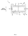
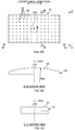
- Fig. 1 to Fig. 3 are illustrative pictures of the disposable diaper 1.
- Fig. 1 is a plan view of the diaper 1
- Fig. 2A is a II-II cross section view in Fig. 1
- Fig. 2B is a same cross section view of another mode of the diaper 1.
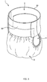
- Fig. 3 is a perspective view of the diaper 1.
- This diaper 1 includes an abdominal side belt member 20 that covers an abdominal side part of a wearer, a back side belt member 24 that covers a back side section, and an absorbent main body 10 that absorbs bodily fluid such as urine by being applied in between the crotches.
- an abdominal side belt member 20 that covers an abdominal side part of a wearer
- a back side belt member 24 that covers a back side section
- an absorbent main body 10 that absorbs bodily fluid such as urine by being applied in between the crotches.
- the abdominal side belt member 20 and the back side belt member 24 are arranged in parallel with an interval therebetween, the above both end sections 10e, 10e in a longitudinal direction of the absorbent main body 10 are put across and fixed therebetween, and its exterior shape is a substantially H-shape in plan view.
- the absorbent main body 10 includes an absorbent body 11 that is made by molding liquid absorbent fiber such as pulp fiber into a substantially rectangular shape in plan view, a surface sheet member 12 that covers the absorbent body 11 from a side to the wearer's skin, and a back surface sheet member 13 that covers the absorbent body 11 from an opposite side of the surface sheet member 12 and also serves as an exterior of the diaper 1.
- the absorbent body 11 may include superabsorbent polymer.
- the surface sheet member 12 is, for example, a fluid permeable nonwoven fabric with a size in a plane larger than the absorbent body 11.
- the back surface sheet member 13 is a fluid non-permeable sheet with a size in a plane larger than the absorbent body 11, and as one example thereof there is given a sheet 13 having a two-layer configuration with a fluid non-permeable leakproof sheet 14 of such as polyethylene and an exterior sheet 15 such as a nonwoven fabric adhered together. Then, in a state in which the absorbent body 11 is sandwiched in between the back surface sheet member 13 and the surface sheet member 12, in a section that lies outside of the four sides of the absorbent body 11, the back surface sheet member 13 and the surface sheet member 12 are adhered together in a frame state, and thus the absorbent main body 10 is formed.
- a fluid permeable sheet 16 such as a tissue paper may be interposed in between the surface sheet member 12 and the absorbent body 11 and in between the back surface sheet member 13 and the absorbent body 11. Further, in both end sections in a width direction in the back surface sheet member 13, an elastic member 17 such as an elastic string may be interposed and fixed in an extended state along a longitudinal direction in between the leakproof sheet 14 and the exterior sheet 15, and in this way with these elastic members 17 each of the leg openings 5, 5 of the diaper 1 are formed with an around-leg gather section and elasticity is given.
- the abdominal side belt member 20 and the back side belt member 24 both have, for example, a flexible sheet such as a nonwoven fabric as the material.
- each of the belt members 20, 24 are formed by double layering the nonwoven fabrics 21, 21, and each of the belt members 20, 24 are adhered to and fixed to the corresponding end sections 10e, 10e in the longitudinal direction of the absorbent main body 10.
- the end sections 10e, 10e in the longitudinal direction of the absorbent main body 10 may be interposed and fixed in between the double layered nonwoven fabrics 21, 21.
- each of the belt members 20, 24 may be fixed with an elastic member such as an elastic string in an extended state, and these belt members 20, 24 may be given elasticity.
- Such a diaper 1 is completed, with any part that continuously flows in a manufacturing line as a base material, by, for example, bonding various parts to this base material.
- the method of manufacturing and the manufacturing apparatus 31 according to this embodiment serve one step thereof.
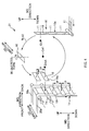
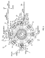
- Fig. 4 is a schematic diagram of a process to be performed in this manufacturing apparatus 31, and Fig. 5 is an illustrative picture of the manufacturing apparatus 31.
- a width direction of manufacturing apparatus 31 is referred to as a "CD direction”
- a direction that intersects this CD direction is referred to as an "MD direction”.
- the MD direction refers to any given direction in a plane that intersects with the CD direction.
- the 2 directions that intersect with each other in the MD direction may each be referred to as an "up-down direction” and a "front-back direction”.
- a process of putting the absorbent main body 10 over a pair of the belt members 20, 24 and adhering it thereto is performed, and thus a semifinished product of the diaper 1 becomes a substantially H-shape as shown in Fig. 1 .
- a pair of the belt members 20, 24 when being supplied to the manufacturing apparatus 31 is being continuously transported in a form of continuous bodies 20a, 24a along the MD direction, and in a state side by side with an interval between each other in the CD direction.
- the absorbent main body 10 is also continuously transported in a form of the continuous body 10a that continues in the MD direction. That is to say, the surface sheet member 12 and the back surface sheet member 13 configuring the absorbent main body 10 are in a state of continuous sheets that continue in a longitudinal direction of the absorbent main body 10, and the absorbent body 11 is interposed in between the surface sheet member 12 and back surface sheet member 13 and each absorbent body 11 is in a state arranged periodically in the longitudinal direction.
- the continuous body 10a of the absorbent main body is divided along the CD direction in a region in between the absorbent bodies 11, 11, and thus the absorbent main body 10 with the longitudinal direction facing the MD direction is formed.
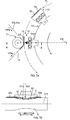
- a rotating drum 42 that drives and rotates around a center of axis C41 along the CD direction receives the absorbent main body 10 on a peripheral surface thereof, and in the process of moving the absorbent main body 10 from this receiving position (hereinbelow, referred to as receiving position Qin) to a predetermined delivery position Qout with the drive rotation of the rotating drum 42, by turning the absorbent main body 10 90 degrees about a center of the plane, the longitudinal direction of the absorbent main body 10 is changed from the MD direction to the CD direction that is a parallel direction to the continuous bodies 20a, 24a of the belt member.
- a transport roller 71 is arranged in the delivery position Qout, and a pair of the continuous bodies 20a, 24a of the belt member are wrapped around the transport roller 71 in the CD direction and continuously transported in the MD direction. Therefore, when the absorbent main body 10 passes by the delivery position Qout with the drive rotation of the rotating drum 42, both end sections 10e, 10e in the longitudinal direction of the absorbent main body 10 are adhered to the pair of continuous bodies 20a, 24a of the belt member.
- a semifinished product 1a of a substantially ladder shape in Fig. 4 which is a stage before the substantially H-shape in Fig. 1 described above, is formed.
- the absorbent main body 10 corresponds to "the first sheet-like member”
- the pair of the continuous bodies 20a, 24a of the belt member corresponds to “the second sheet-like member”
- the substantially ladder shaped semifinished product 1a corresponds to "the composite body of the sheet-like member of the absorbent article”.
- each of the configuring elements 61, 41, 71 of this manufacturing apparatus 31 are described.
- the cutter device 61 has a pair of upper and lower rolls 61a, 61b that continuously drives and rotates in a predetermined peripheral speed V61 about centers of axes C61a, C61b along the CD direction.
- the peripheral speed V61 is set at, for example, substantially a same speed as a transport velocity V10a of the continuous body 10a of the absorbent main body.
- the peripheral surface of the upper roll 61a is a smooth surface. Then, the upper roll 61a is arranged so that the peripheral surface thereof opposes the rotating drum device 41 so that it is closest in the receiving position Qin. Further, on the peripheral surface of the lower roll 61b is provided one flat blade 62 along the CD direction, and a perimeter of the peripheral surface is substantially the same as a length in design of the absorbent main body 10.
- the continuous body 10a of the absorbent main body is sent continuously in the MD direction with the drive rotation of these upper and lower rolls 61a, 61b, by the flat blade 62 of the lower roll 61b opposing the peripheral surface of the upper roll 61a and sandwiching the continuous body 10a of the absorbent main body, the absorbent main body 10 for the length part in design is divided and formed in a front end side of this continuous body 10a.
- a plurality of suction holes are included on its peripheral surface. Then, in respect to a circumferential direction of the upper roll 61a, suction operation with these suction holes is performed at all times over a range from a position closest to the lower roll 61b to a position opposing the receiving position Qin. Therefore, the absorbent main body 10 that is divided and formed, and a front end section of the continuous body 10a that has been newly formed by dividing are both firmly sucked and held on the peripheral surface of the upper roll 61a and securely sent to the receiving position Qin of the rotating drum device 41.
- the rotating drum device 41 includes the rotating drum 42 that drives and rotates about the center of axis C41 along the CD direction and a plurality of sheets (8 sheets in the example shown) of the workpiece holding pallets 51 (corresponds to holding sections) supported side by side in equal pitch in the circumferential direction of the peripheral surface of the rotating drum 42 in order to hold the absorbent main bodies 10.
- the rotating drum 42 is a substantially cylindrical member, and drives and rotates in a predetermined angular velocity for example in one direction counterclockwise with an appropriate motor and the like as a driving source. Then, as a result each of the workpiece holding pallets 51 moves on a perfect circle shape trajectory Tr with the center of axis C41 as the center of the circle in a predetermined moving velocity V51 based on the angular velocity.
- each of the workpiece holding pallets 51 receives the absorbent main body 10 from the cutter device 61, and in the delivery position Qout, in cooperation with the transport roller 71 in the same position Qout, the absorbent main body 10 on the workpiece holding pallet 51 is bonded and delivered to the pair of the continuous bodies 20a, 24a of the belt member.
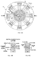
- Fig. 6A is a front view of the workpiece holding pallet 51
- Fig. 6B is a B-B arrow view in Fig. 6A
- Fig. 6C is a C-C arrow view in Fig. 6A .
- the workpiece holding pallet 51 is a substantially rectangular shaped plate shaped member having a holding surface 53 that holds the absorbent main body 10 in a surface contacting state, and as shown in Fig. 5 the holding surface 53 is faced toward the outside in the rotating radius direction of the rotating drum 42.
- a suction hole 54 (corresponds to holes) over substantially the entire surface thereof, and these suction hole 54 are connected to a negative pressure zone Z1 to be described later via a suction chamber 56 and a duct such as a suction pipe 81 inside the workpiece holding pallet 51. Therefore, with the suction air from these suction holes 54, suction force to hold the absorbent main body 10 is generated on the holding surface 53.
- This suction operation is performed over a range from the receiving position Qin to the delivery position Qout in Fig. 5 , and is generally stopped in other ranges. It should be noted that, this suction operation is to be described later.
- the longitudinal direction of the holding surface 53 is aligned with the longitudinal direction of the workpiece holding pallet 51. Therefore, as will be described later, in the case the longitudinal direction of the workpiece holding pallet 51 in the receiving position Qin is made to face the MD direction, the absorbent main body 10 that is sent from the cutter device 61 in a state the longitudinal direction is facing the MD direction can be held firmly with the holding surface 53. Furthermore, as shown in Fig. 6A , the holding surface 53 is formed in an arc shape in section along the longitudinal direction, and its radius of curvature R53 is substantially a same value as a rotating radius of a trajectory Tr in Fig. 5 .
- a moving velocity V51 of the workpiece holding pallet 51 in the receiving position Qin can be maintained at a constant velocity over the entire length in the longitudinal direction of the workpiece holding pallet 51. Therefore, in the case an angular velocity of the rotating drum 42 is set so that the moving velocity V51 of the workpiece holding pallet 51 is the same as a transport velocity V10a of the continuous body 10a of the absorbent main body, the workpiece holding pallet 51 can receive the absorbent main body 10 that is sent from the cutter device 61 in an extended state almost without any creases over its entire length.
- the workpiece holding pallet 51 is turnable about a turning center of axis C53 that passes a center on a plane of the holding surface 53 and is along a rotating radius direction of the rotating drum 42. Therefore, by the workpiece holding pallet 51 being turned around this turning center of axis C53, the absorbent main body 10 on the workpiece holding pallet 51 also turns together with the workpiece holding pallet 51, and thus the longitudinal direction of the absorbent main body 10 is changed from the MD direction to the CD direction.
- the workpiece holding pallet 51 turns 90 degrees again in order to receive the absorbent main body 10 in the receiving position Qin, and thus the longitudinal direction of the workpiece holding pallet 51 is returned from the CD direction to the MD direction.
- An appropriate motor and the like can be given as a driving source of this turning operation.
- Fig. 7A is an enlarged view of a transport roller 71 arranged in the delivery position Qout
- Fig. 7B is a B-B cross section view in Fig. 7A
- the transport roller 71 is a follower roller 71 that is rotatably supported around the center of axis C71 facing the CD direction.
- a pair of continuous bodies 20a, 24a of the belt member is wrapped around the peripheral surface of the transport roller 71 and is made to follow and rotate with the travel of the continuous bodies 20a, 24a.
- a traveling velocity V20a (transport velocity) of the pair of the continuous bodies 20a, 24a of the belt member is set at approximately a same value as the moving velocity V51 of the workpiece holding pallet 51 of the rotating drum 42.
- an external shape of the transport roller 71 is in a shape that is concave in a central section in the CD direction, in correspondence with a convex shape ( Fig. 6B ) of the holding surface 53 of the workpiece holding pallet 51.
- the shape of the holding surface 53 of the workpiece holding pallet 51 is in an arc shape in which the central section bulges outward more than both end sections in the longitudinal direction in a rotating radius direction of the rotating drum 42, as described above.
- the shape of the peripheral surface of the transport roller 71 is set in an arc shape with a roll curve in which a radius of the transport roller 71 gradually becomes smaller from the end sections in the CD direction to the central section. Then, as a result of this, the transport roller 71, with the workpiece holding pallet 51 passing the delivery position Qout, sandwiches the absorbent main body 10 over an entire length in its CD direction substantially equally and can securely hold the absorbent main body 10.
- a radius of curvature R71 of this roll curve is made equal to or greater than the radius of curvature R53 of the arc shape of the workpiece holding pallet 51, and equal to or smaller than 1.2 times the radius of curvature R53, and more preferably, to a radius of curvature greater than the radius of curvature R53.
- the holding surface 53 and the transport roller 71 can be prevented from strongly contacting locally the absorbent main body 10 in both end sections in the CD direction, and as a result the damage the absorbent main body 10 may receive can be lessened.
- a flexible material that elastically deforms at least in a peripheral section with a contact pressure when the workpiece holding pallet 51 is contacted is preferable, and as one example thereof there can be given a sponge form polyurethane rubber and the like. Then, by using such a material, during delivery the absorbent main body 10 that is sandwiched with the workpiece holding pallet 51 and the transport roller 71 can be prevented from being largely damaged.
- Fig. 8A to Fig. 8E are illustrative pictures of the manner of delivery of the absorbent main body 10 that is performed in the delivery position Qout.
- the pair of continuous bodies 20a, 24a of the belt member are wrapped around and continuously transported, and a part of the peripheral surface of the transport roller 71 is positioned in the delivery position Qout on the trajectory Tr.
- the holding surface 53 of the workpiece holding pallet 51 also passes by the delivery position Qout along the trajectory Tr. Then, when each of the sections of the absorbent main body 10 that has been held on the holding surface 53 passes by the delivery position Qout, each of the sections subsequently adheres to the pair of continuous bodies 20a, 24a of the belt member on the peripheral surface of the transport roller 71 and is delivered to the continuous bodies 20a, 24a. Therefore, this delivery operation takes on the semblance of transfer to a curved surface along the peripheral surface of the transport roller 71, in other words, a so-called curved surface transfer.
- the delivery operation of the absorbent main body 10 from the holding surface 53 to the pair of continuous bodies 20a, 24a of the belt member is not performed simultaneously over the entire surface of the holding surface 53, and is performed so that an area in which the absorbent main body 10 is delivered to the holding surface 53 is sequentially shifted from a downstream side to an upstream side in the trajectory Tr. That is to say, the delivering timing is shifted between at least an area 55d in the downstream side of the holding surface 53 (hereinbelow, also referred to as a downstream side area) and an area 55u in the upstream side (hereinbelow, also referred to as an upstream side area).
- the absorbent main body 10 can be said to include a section to be delivered first (a section to be held in a downstream side area 55d) and a section to be delivered subsequently (a section to be held in an upstream side area 55u).
- a suction configuration of the holding surface 53 as shown in a cross section view in Fig. 9 (corresponds to a cross section view in IX-IX section in Fig. 6A ), just one substantially closed space in a negative pressure state that is partitioned and formed as a suction chamber 156 inside the workpiece holding pallet 51, and this suction chamber 156 is in communication with all the suction holes 54 on the holding surface 53 so as to allow air to pass through.
- the suction holes 54 of this downstream side area 55d take the lead to suck in a large amount of outside air in a state in which it can suck with a small suction resistance, and a negative pressure level of the suction chamber 156 increases to an extreme.
- the suction force of the suction holes 54 in the upstream side area 55u of the holding surface 53 becomes small, and the holding property of the upstream side area 55u significantly decreases.
- the section corresponding to the upstream side area 55u of the absorbent main body 10 is deformed or the like before being delivered, and there is a possibility that the attaching precision to the pair of continuous bodies 20a, 24a of the belt member decreases.
- both end sections in the width direction of the absorbent main body 10 in Fig. 1 are fixed with an elastic member 17 to form an around-leg gather section, and in the state the absorbent main body 10 is held on the holding surface 53, the elastic member 17 is in a state extended in the longitudinal direction of the absorbent main body 10. Therefore, in a latter half of a series of the delivery operations, in the case the suction force of the upstream side area 55u of the holding surface 53 shown in Fig. 9 decreases, one end section in the width direction of the absorbent main body 10 to be sucked and held with the upstream side area 55u cannot go against contractive force of the elastic member 17 and contracts in the longitudinal direction. As a result, as shown in Fig. 10 the absorbent main body 10 is adhered to the pair of the continuous bodies 20a, 24a of the belt member in an asymmetrical shape in the width direction.
- the holding surface 53 of the workpiece holding pallet 51 is divided into two of at least the upstream side area 55u and the downstream side area 55d, and suction chambers 56u, 56d are provided for each of the areas 55u, 55d inside the workpiece holding pallet 51, and these suction chambers 56u, 56d are partitioned so as not to allow air through to each other (refer to Fig. 11A to Fig. 11C ).
- the areas are divided so the suction air state of the suction holes 54 in the downstream side area 55d of the holding surface 53 do not affect the suction holes 54 in the upstream side area 55u, and as a result the decrease in the suction force of the upstream side area 55u of the holding surface 53 that may occur in the latter half of the delivery operation can be prevented.
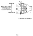
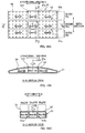
- Fig. 11A is a plan view showing a division of an area 55 of the workpiece holding pallet 51 of this embodiment
- Fig. 11B is a B-B cross section view in Fig. 11A
- Fig. 11C is a C-C cross section view in Fig. 11A .
- the holding surface 53 of the workpiece holding pallet 51 is divided into three areas 55 in its width direction.
- the holding surface 53 is divided into the downstream side suction area 55d positioned in a downstream side of the trajectory Tr when delivering, the upstream side suction area 55u positioned in an upstream side than this downstream side suction area 55d, and the middle suction area 55m positioned in between these suction areas 55d, 55u.
- three suction chambers 56 are partitioned with an approximately equal capacity to each other, and in a chamber form that does not allow air to pass through to each other (in a state surrounded by wall sections from all directions in the space).
- two division walls 57a, 57b along the longitudinal direction of the holding surface 53 are arranged side by side to each other in the width direction, and the three suction chambers 56 are separated from each other by these division walls 57a, 57b so as not to allow air to pass through to each other.
- these three suction chambers 56 namely, the downstream side suction chamber 56d (corresponds to a first suction chamber), the middle suction chamber 56m (corresponds to a third suction chamber), and the upstream side suction chamber 56u (corresponds to a second suction chamber) are each connected with exclusive suction pipes 81d, 81m, 81u via a middle chamber member 83 to be described later (refer to Fig. 12B ), and each suction pipe 81d, 81m, 81u is configured to be able to independently suck out air in each corresponding suction chamber 56.
- a suction pipe for the downstream side suction chamber 56d is also referred to as a downstream side suction pipe 81d
- a suction pipe for the middle suction chamber 56m is also referred to as a middle suction pipe 81m
- a suction pipe for the upstream side suction chamber 56u is also referred to as an upstream side suction pipe 81u.
- each of the suction areas 55d, 55m, and 55u stops and weakens suction independently from each of the other suction areas 55, in correspondence to the delivery operation of the section of the absorbent main body 10 that each area is in charge of. That is to say, in the case that each of the suction areas 55 of the downstream side suction area 55d, the middle suction area 55m, and the upstream side suction area 55u passes by the delivery position Qout, each of the suction areas 55d, 55m, and 55u may stop suction of its own area independently of the other suction areas 55.
- each of the suction areas 55d, 55m, 55u when sandwiching the pair of the continuous bodies 20a, 24a of the belt member with the transport roller 71 and contacting the transport roller 71, may stop suction of its own area independently of the other suction areas 55.
- a suction air configuration that can independently stop the suction operation subsequently in units of the suction area 55, in response to the delivery operation of each of the suction areas 55d, 55m, 55u in this way, there is given a configuration such as that shown in Fig. 12A and Fig. 12B.
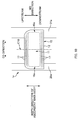
- Fig. 12A is an A-A arrow view in Fig. 5
- Fig. 12B is a B-B cross section view in Fig. 12A .
- a negative pressure chamber drum 85 to be described later is shown in a central vertical section view.
- this suction air configuration has the negative pressure chamber drum 85 that has a part of an internal space that has been set as a negative pressure zone Z1, as a negative pressure source, and a middle chamber member 83 that has been arranged for each workpiece holding pallet 51 opposing the workpiece holding pallet 51 in a position to an inner side in the rotating radius direction of the rotating drum 42 than the workpiece holding pallet 51, in order to relay between the negative pressure chamber drum 85 and the suction chamber 56 of the workpiece holding pallet 51.
- each middle chamber member 83 is in communication with the internal space of the negative pressure chamber drum 85 with the above-described three suction pipes 81 provided for each of the middle chamber member 83, and thus each middle chamber member 83 performs the suction operation of the workpiece holding pallet 51 that each is in charge of.
- each chamber 84 is formed with a substantially equal capacity to each other, and is each corresponded to any one of the downstream side suction chamber 56d, the middle suction chamber 56m, and the upstream side suction chamber 56u in the workpiece holding pallet 51.
- each chamber 84 is connected so as to allow air to pass through with one end opening 82a of one corresponding suction pipe 81 out of the three suction pipes 81.
- each chamber 84 is in communication with all the suction chambers 56d, 56m, 56u, but on the contrary, in a state in which the longitudinal direction is facing the CD direction, each chamber 84 is configured so as to be in communication with only the corresponding suction chamber 56. Therefore, in a state the longitudinal direction of the workpiece holding pallet 51 is facing the MD direction, all three suction pipes 81d, 81m, 81u cooperate to perform the suction operation of each suction chamber 56, and in a state in which the longitudinal direction of the workpiece holding pallet 51 is facing the CD direction, the suction operation of each suction chamber 56 is performed with only one corresponding suction pipe 81.
- the suction operation of the downstream side suction chamber 56d is performed with only the downstream side suction pipe 81d
- the suction operation of the middle suction chamber 56m is performed with only the middle suction pipe 81m
- the suction operation of the upstream side suction chamber 56u is performed with only the upstream side suction pipe 81u.
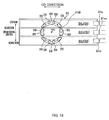
- the negative pressure chamber drum 85 has as a main body a cylindrical body that is arranged in parallel with a same core as the rotating drum 42 and that becomes integral with the rotating drum 42 and rotates at a same speed.
- a doughnut-shaped space inside the cylindrical body is divided into zones of a negative pressure zone Z1 and a non-negative pressure zone Z0 in a circumferential direction with an appropriate partition wall not shown.
- the negative pressure zone Z1 is connected to a decompressor such as a blower with an appropriate piping that is not shown, and is always maintained in a negative pressure state that is lower by a predetermined level than an outside atmospheric pressure.
- the non-negative pressure zone Z0 is maintained in an outside atmospheric pressure or a positive pressure that is slightly higher than the outside atmospheric pressure. Then, the negative pressure zone Z1 is set corresponding to an angle range from the receiving position Qin to the delivery position Qout, and the non-negative pressure zone Z0 is set corresponding to an angle range from the delivery position Qout to the receiving position Qin.
- each suction pipe 81 is made to communicate with the above-described negative pressure zone Z1 and the non-negative pressure zone Z0. Then, the connection positions of these other end openings 82b to the negative pressure chamber drum 85, as shown in Fig.
- each suction pipe 81 when the rotating drum 42 rotates, with the negative pressure chamber drum 85 that rotates integrally with the rotating drum each suction pipe 81 also moves around the perimeter of the negative pressure zone Z1 and the non-negative pressure zone Z0, and in such a case a timing that the other end opening 82b of the suction pipe 81 enters the non-negative pressure zone Z0 is shifted between each other of the three suction pipes 81d, 81m, 81u. Then, as a result in the case each suction area 55d, 55m, 55u passes by the delivery position Qout, the suction operation can be stopped by units of the suction area 55 subsequently and independently of the order in which it passes. In other words, working together with the delivery operation of each of the suction areas 55d, 55m, 55u, the stopping of suction in units of the suction area 55 can be achieved.
- the non-negative pressure zone Z0 is made to be a positive pressure state higher than the outside atmospheric pressure.
- each suction area 55 that has passed by the delivery position Qin sequentially blows out air toward the absorbent main body 10 from the suction holes 54. That is to say, each suction area 55d, 55m, 55u shown in Fig. 8A to Fig. 8E , blasts air in order of the downstream side suction area 55d, the middle suction area 55m, and the upstream side suction area 55u, which is the order in which the suction operation was stopped.
- suction force that has a possibility of remaining even after passing the delivery position Qout can cease to exist completely, and delivering performance of the absorbent main body 10 to the continuous bodies 20a, 24a of the belt member can be greatly increased. Further, foreign matters such as fiber pieces that have adhered to the holding surface 53 of the workpiece holding pallet 51 can also be removed and purification performance becomes high, and also clogging of the suction holes 54 can be prevented in advance.
- connection position of each suction pipe 81 to the other end opening 82b of the negative pressure chamber drum 85 is arranged shifted in respect to each other in a direction along a center of axis C41 of the rotating drum 42, and as shown in Fig. 13A and Fig. 13B (a B-B arrow view in Fig. 13A ), a boundary line BL of the negative pressure zone Z1 and the non-negative pressure zone Z0 is preferably positioned shifted in the circumferential direction of the negative pressure chamber drum 85 in respect to each other between each of the suction pipes 81d, 81m, 81u.
- connection positions of each of the other end openings 82b is set side by side in a direction along the center of axis C41.
- each boundary line BL of the suction pipes 81d, 81m, 81u are shifted in the circumferential direction in respect to each other in an order opposite to an aligning order in the circumferential direction of the other end openings 82b of the suction pipes 81d, 81m, 81u, in other words, the boundary line BLm for the middle suction pipe 81m is positioned in a downstream side than the boundary line BLd for the downstream side suction pipe 81d, further the boundary line BLu for the upstream side suction pipe 81u is positioned in the downstream side than the boundary line BLm, and an external shape of these boundary lines BL form a substantially step form.
- the negative pressure chamber drum 85 can be made small in diameter, and thus the power needed for driving and rotating the negative pressure chamber drum 85 can be decreased. Further, freedom in design in size of the negative pressure chamber drum 85 can be increased.
- the workpiece holding pallet 51 is provided to the peripheral surface of the rotating drum 42, and the workpiece holding pallet 51 is moved in a trajectory Tr of a perfect circle shape, but it is not limited thereto, and it may be moved in a trajectory of a polygon shape such as a rectangle.
- the diaper 1 in the mode in Fig. 2A was manufactured, but it is not limited thereto, and the diaper 1 in the mode in Fig. 2B can be manufactured using the manufacturing apparatus 31 in Fig. 5 .
- the pair of the continuous bodies 20a, 24a of the belt member in the delivery position Qout is not transported in state in which the nonwoven fabric 21 is layered in two, and each continuous body 20a, 24a is transported in a one sheet state.
- the absorbent main body 10 is adhered to the continuous bodies 20a, 24a of the belt member made of one sheet of the nonwoven fabric 21 to form a ladder form semifinished product.
- the continuous bodies 20a, 24a of the belt member made of one sheet of the nonwoven fabric is further joined to the semifinished product, and the continuous bodies 20a, 24a are adhered superimposed on the continuous bodies 20a, 24a of the belt member of the semifinished product and sandwiching each end section 10e, 10e in the longitudinal direction of the absorbent main body 10.
- a semifinished product of the diaper 1 corresponding to Fig. 2B is manufactured.
- the disposable diaper 1 that absorbs excretory fluid such as urine as an absorbent article is illustrated, but it is not limited thereto, and it may be applied to manufacture of a sanitary napkin that absorbs excretory fluid such as menstrual blood.
- three suction areas 55d, 55m, 55u are provided on the holding surface 53, and a total of three suction chambers 56d, 56m, 56u are partitioned inside the workpiece holding pallet 51 in correspondence to each suction area 55d, 55m, 55u, but as long as these numbers are a multiple, for example, the number of the suction area 55 and the number of the suction chamber 56 may be equal to or greater than two or four.
- the workpiece holding pallet 51 is fixed such that it cannot move relatively in the circumferential direction of the rotating drum 42 in respect to the rotating drum 42, but it is not limited thereto.
- each workpiece holding pallet 51 may be provided to be able to move reciprocatingly in the circumferential direction of the rotating drum 42 relatively in respect to the rotating drum 42. Then, in this case, since not only the rotating drum 42, but also each workpiece holding pallet 51 moves reciprocatingly, an orbiting operation on the trajectory Tr in an absolute coordinate system of each workpiece holding pallet 51 becomes a complex operation of a counterclockwise rotating operation of the rotating drum 42 itself combined with the reciprocating movement operation.
- this complex operation may be allocated in correspondence to each rotation position on the trajectory Tr, and in that case the orbiting operation of the workpiece holding pallet 51 on the absolute coordinate system is to be performed based on a predetermined velocity pattern that is made by corresponding a moving velocity V51 in the circumferential direction to each rotation position.
- each workpiece holding pallet 51 repeats an orbiting operation based on a velocity pattern that has one 360 degrees rotation as one period.
- Japanese Patent Application Laid-open Publication No.2005-298193 can be illustrated.
- the suction chambers 56d, 56m, 56u inside the workpiece holding pallet 51 are partitioned into a chamber form in a state that does not allow air to pass through each other at all times, but it is not limited thereto.
- the absorbent main body 10 is configured to be able to be delivered to the pair of the continuous bodies 20a, 24a of the belt member, in a state in which the downstream side suction chamber 56d and the upstream side suction chamber 56u are partitioned so that air is not allowed to pass through to each other, the configuration can be other than that described above.
- the workpiece holding pallet 51 has, instead of the above-described suction chamber 56, a recessed section that is in communication with the suction holes 54 of the holding surface 53 on the opposite surface to the holding surface 53. Further, this recessed section is divided into three recessed sections 59d, 59m, 59u with rib form division walls 57c, 57d, and each of the recessed sections 59d, 59m, 59u is corresponded to each of the suction areas 55d, 55m, 55u. Further, these three recessed sections 59d, 59m, 59u are covered with a movable wall 92, and thus are shielded from an adjacent negative pressure space SP.
- each of the recessed sections 59d, 59m, 59u is in a state opposed to each of the through holes 94d, 94m, 94u that have been formed through the movable wall 92 corresponding to each of these recessed sections 59d, 59m, 59u.
- each of the recessed sections 59d, 59m, 59u is made to be in communication with a negative pressure space SP via corresponding through holes 94d, 94m, 94u, and as a result, the suction force is generated on the holding surface 53 of the workpiece holding pallet 51.
- each of the recessed sections 59d, 59m, 59u at this time are in a state partitioned so as not to allow air to pass through to each other, and thus decrease in the suction force of the upstream side area 55u of the holding surface 53 that may occur in the latter half of the delivery operation can be effectively prevented.
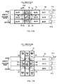
- the internal space of the workpiece holding pallet 51 is partitioned into the three suction chambers 56d, 56m, 56u in the width direction of the holding surface 53, but it is not limited thereto, and each of the suction chambers 56d, 56m, 56u may be further partitioned into a plurality of suction chambers 56 in the longitudinal direction of the holding surface 53.
- two division walls 57e, 57f along the width direction are arranged side by side in the longitudinal direction, and with these division walls 57e, 57f the suction chamber 56d is partitioned into three suction chambers 56dd, 56dm, 56du that do not allow air to pass through to each other, the suction chamber 56m is partitioned into three suction chambers 56md, 56mm, 56mu that do not allow air to pass through to each other, and the suction chamber 56u is partitioned into three suction chambers 56ud, 56um, 56uu that do not allow air to pass through to each other.
- holding property can be increased not only during delivery but also during receiving of the absorbent main body 10, and it will be more preferable.
- the configuration of the middle chamber member 83 is similar to the above-described embodiment mode.
- the internal space of the middle chamber member 83 is partitioned into three chambers 84 in a direction along the trajectory Tr. More specifically, from the downstream side to the upstream side of the trajectory Tr, the internal space is partitioned into the downstream side chamber 84d, the middle chamber 84m, and the upstream side chamber 84u. Further, the middle chamber member 83 is fixed immovably to the rotating drum 42, and the relative positional relationship of these chambers 84d, 84m, 84u to each other is non-changing.
- the workpiece holding pallet 51 turns about the turning center of axis C53, so that the positional relationship between the suction chambers 56, 56, ... 56 in the upstream and downstream direction of the trajectory Tr changes, between a state in which the longitudinal direction of the workpiece holding pallet 51 is facing the CD direction and a state in which it is facing the MD direction.
- the suction chamber 56 that is relatively positioned in the downstream side in its direction may be configured to be in communication with the downstream side chamber 84d of the middle chamber member 83 so as to allow air to pass through
- the suction chamber 56 that is relatively positioned in the center may be configured to be in communication with the middle chamber 84m of the middle chamber member 83 so as to allow air to pass through
- the suction chamber 56 that is relatively positioned in the upstream side may be configured to be in communication with the upstream side chamber 84u of the middle chamber member 83 so as to allow air to pass through.
- the downstream side chamber 84d in a state in which the longitudinal direction of the workpiece holding pallet 51 is facing the CD direction, the downstream side chamber 84d is in communication with the suction chambers 56dd, 56dm, 56du relatively positioned in the downstream side in this state, the middle chamber 84m is in communication with the suction chambers 56md, 56mm, 56mu relatively positioned in the center, and the upstream side chamber 84u is in communication with the suction chambers 56ud, 56um, 56uu relatively positioned in the upstream side.
- the middle chamber 84m is in communication with the suction chambers 56md, 56mm, 56mu relatively positioned in the center
- the upstream side chamber 84u is in communication with the suction chambers 56ud, 56um, 56uu relatively positioned in the upstream side.
- the downstream side chamber 84d may be configured to be in communication with the suction chambers 56dd, 56md, 56ud relatively positioned in the downstream side in this state
- the middle chamber 84m may be configured to be in communication with the suction chambers 56dm, 56mm, 56um relatively positioned in the center
- the upstream side chamber 84u may be configured to be in communication with the suction chambers 56du, 56mu, 56uu relatively positioned in the upstream side.
- a problem of decrease in the suction force similar to that described above in the delivery position Qout may occur. That is to say, in the first half of the receiving operation, as shown in Fig. 5 , an area in the upstream side with a small suction resistance and that is not covered by the absorbent main body 10 leads in sucking the outside air into the suction chamber 156, and as a result the negative pressure level of the suction chamber 156 is greatly decreased, and holding property of the absorbent main body 10 in the area in the downstream side is significantly decreased.
- the suction chambers 56d, 56m, 56u are further partitioned into three in the longitudinal direction of the holding surface 53, the suction chambers 56dd, 56md, 56ud corresponding to the area in the downstream side and the suction chambers 56du, 56mu, 56uu corresponding to the area in the upstream side can perform the suction operation independently from each other, so that decrease in the suction force in the area in the downstream side that may occur in the first half of the receiving operation of the absorbent main body 10 can be effectively prevented. As a result, poor holding of the absorbent main body 10 can also be effectively prevented.
- the below configuration can be illustrated.
- Fig. 17A in a state the turning center of axis C53 of the workpiece holding pallet 51 is aligned to a central position in the upstream and downstream direction (width direction) of the middle chamber member 83, the workpiece holding pallet 51 is arranged superposed on the middle chamber member 83. Further, in a region of a wall section of the workpiece holding pallet 51 opposing the middle chamber member 83, and a region above a perfect circle pitch circle P59 with a center as the turning center of axis C53, at least one or more through hole 59 is formed for each suction chamber 56, 56, ...
- the through hole 89 is formed also in a region opposing the through hole 59 of the workpiece holding pallet 51 in a wall section of the middle chamber member 83 (refer to Fig. 18 ).
- these through holes 89 are not formed across the chambers 84d, 84m, 84u, and any of the through holes 89 are formed in a size which can fit in the chamber 84 that the through hole 89 belongs to.
- the through hole 59 of each suction chamber 56 is not formed across adjacent suction chambers 56, 56, and any of the through holes 59 are formed in a size which can fit in the suction chamber 56 that the through hole 59 belongs to.
- the suction chambers 56, 56, 56 relatively positioned in the downstream side in its direction are in communication with only the downstream side chamber 84d
- the suction chambers 56, 56 relatively positioned in the center are in communication with only the middle chamber 84m
- the suction chambers 56, 56, 56 relatively positioned in the upstream side are in communication with only the upstream side chamber 84u.
- the suction chambers 56, 56, 56 relatively positioned in the downstream side, the suction chambers 56, 56 relatively positioned in the center, and the suction chambers 56, 56, 56 relatively positioned in the upstream side can perform the suction operation independently in a state partitioned so as not to allow air to pass through to each other.
Landscapes
- Health & Medical Sciences (AREA)
- Engineering & Computer Science (AREA)
- Life Sciences & Earth Sciences (AREA)
- Biomedical Technology (AREA)
- Heart & Thoracic Surgery (AREA)
- Vascular Medicine (AREA)
- Epidemiology (AREA)
- Animal Behavior & Ethology (AREA)
- General Health & Medical Sciences (AREA)
- Public Health (AREA)
- Veterinary Medicine (AREA)
- Manufacturing & Machinery (AREA)
- Absorbent Articles And Supports Therefor (AREA)
- Mechanical Engineering (AREA)
Claims (8)
- Verfahren zur Herstellung eines Verbundkörpers (1a) eines folienartigen Elements eines saugfähigen Artikels (1), wobei das Verfahren umfasst:die Aufnahme eines ersten folienartigen Elements (10) auf einer Haltefläche (53) eines Halteabschnitts (51) an einer Aufnahmestelle (Qin), wobei der Halteabschnitt auf der Umfangsfläche einer rotierenden Trommel (42) vorgesehen ist und die rotierende Trommel antreibt und um ein Zentrum einer Achse (C41) entlang einer Richtung CD rotiert, wobei eine sich mit der Richtung CD schneidende Richtung eine Richtung MD ist;das Halten des ersten folienartigen Elements auf der Haltefläche des Halteabschnitts;das Drehen des ersten folienartigen Elements (10) auf der Haltefläche (53) des Halteabschnitts (51) um ein Drehzentrum einer Achse (C53), die an einem Zentrum auf einer Ebene der Haltefläche (53) vorbei geht und sich entlang einer Drehradiusrichtung der rotierenden Trommel (42) erstreckt, wobei die Längsrichtung des ersten folienartigen Elements von Richtung MD auf Richtung CD umgestellt wird; unddas Anliefern und Befestigen des ersten folienartigen Elements von der Haltefläche an einem zweiten folienartigen Element (20a, 24a) an einer Anlieferstelle (Qout),wobei das erste folienartige Element einen bei der Anlieferung zum zweiten folienartigen Element zuerst anzuliefernden Abschnitt und einen danach anzuliefernden Abschnitt aufweist und das erste folienartige Element mit Saugluft aus einer Vielzahl von auf der Haltefläche ausgebildeten Löchern (54) auf der Haltefläche gehalten wird,wobei der Halteabschnitt mindestens zwei Saugkammern (56) aufweist, nämlich eine erste Saugkammer (56d) in Kommunikation mit Löchern, die den zuerst anzuliefernden Abschnitt saugen, und eine zweite Saugkammer (56u) mit Löchern, die den danach anzuliefernden Abschnitt saugen,wobei die Saugkammern jeweils über eine Mittelkammer (83) mit einem ausschließlichen Saugrohr (81) verbunden sind und die Saugrohre jeweils zum unabhängigen Aussaugen von Luft in der zugehörigen Saugkammer (56) ausgelegt sind und die Mittelkammer einen Innenraum hat, der in mindestens zwei im Wesentlichen geschlossene Kammern (84) aufgeteilt ist, die jeweils einer Saugkammer (56) entsprechen,wobei das erste folienartige Element am zweiten folienartigen Element in einem Zustand angeliefert wird, in dem die erste Saugkammer und die zweite Saugkammer so aufgeteilt sind, dass keine Luft von einer zur anderen durchströmen kann; wobeiwobei an der Anlieferstelle, in einem Zustand, in dem die Längsrichtung des Halteabschnitts (51) der Richtung CD zugekehrt ist, die im Wesentlichen geschlossenen Kammern (84) jeweils nur mit der entsprechenden Saugkammer (56) in Kommunikation sind, so dass der Saugvorgang einer jeden Saugkammer nur mit dem entsprechenden Saugrohr erfolgt; undwobei an der Anlieferstelle, in einem Zustand, in dem die Längsrichtung des Halteabschnitts (51) der Richtung MD zugekehrt ist, die im Wesentlichen geschlossenen Kammern (84) jeweils mit allen Saugkammern (56) in Kommunikation sind, so dass alle Saugrohre beim Saugvorgang einer jeden Saugkammer zusammenarbeiten.
- Verfahren zur Herstellung eines Verbundkörpers eines folienartigen Elements eines saugfähigen Artikels nach Anspruch 1, wobei
wenn der zuerst anzuliefernde Abschnitt in einem Anliefervorgang an das zweite folienartige Element angeliefert wird, Saugluft aus den Löchern, die den zuerst anzuliefernden Abschnitt saugen, geschwächt wird, und
wenn der danach anzuliefernde Abschnitt in einem Anliefervorgang an das zweite folienartige Element angeliefert wird, Saugluft aus den Löchern, die den danach anzuliefernden Abschnitt saugen, geschwächt wird. - Verfahren zur Herstellung eines Verbundkörpers eines folienartigen Elements eines saugfähigen Artikels nach Anspruch 2, wobei
die Löcher, wo die Saugluft geschwächt wurde, Luft in einer Reihenfolge, in der die Löcher geschwächt wurden, in Richtung des ersten folienartigen Elements blasen. - Verfahren zur Herstellung eines Verbundkörpers eines folienartigen Elements eines saugfähigen Artikels nach einem der Ansprüche 1 bis 3, wobei
eine dritte Saugkammer (56m) zwischen der ersten Saugkammer (56d) und der zweiten Saugkammer (56u) im Halteabschnitt angeordnet und aufgeteilt ist,
Löcher (54) in Kommunikation mit der dritten Saugkammer zwischen den Löchern in Kommunikation mit der ersten Saugkammer und den Löchern in Kommunikation mit der zweiten Saugkammer ausgebildet und angeordnet sind, und
in einem Zustand, in dem die erste Saugkammer, die zweite Saugkammer und die dritte Saugkammer so aufgeteilt sind, dass keine Luft von einer zur anderen durchströmen kann, das erste folienantige Element an das zweite folienartige Element angeliefert wird. - Verfahren zur Herstellung eines Verbundkörpers eines folienartigen Elements eines saugfähigen Artikels nach einem der Ansprüche 1 bis 4, wobei
sich der Halteabschnitt entlang einer Bahn (Tr) bewegt,
das zweite folienartige Element eine Endlosfolie ist, die an einer Anlieferstelle in der Bahn um eine Rolle (71) gewickelt wird und sich ständig fortbewegt,
während der Halteabschnitt entlang einer Bewegungsrichtung des zweiten folienartigen Elements an der Anlieferstelle vorbei fährt, das erste folienantige Element auf der Haltefläche des Halteabschnitts an das zweite folienartige Element angeliefert wird, und
die den zuerst anzuliefernden Abschnitt saugenden Löcher in einem Bereich auf einer Stromabseite der Bahn der Haltefläche während der Anlieferung ausgebildet sind und die den danach anzuliefernden Abschnitt saugenden Löcher in einem Bereich auf einer Stromaufseite der Haltefläche ausgebildet sind. - Verfahren zur Herstellung eines Verbundkörpers eines folienartigen Elements eines saugfähigen Artikels nach einem der Ansprüche 1 bis 5, wobei
der zuerst anzuliefernde Abschnitt und der danach anzuliefernde Abschnitt jeweils mit einem elastischen Element (17) befestigt sind, das die beiden Abschnitte in einer gleichen Richtung aufeinander hinzu zusammenzieht,
in einem Zustand, in dem der zuerst anzuliefernde Abschnitt mit Saugluft aus den Löchern auf die Haltefläche gesaugt wird, der zuerst anzuliefernde Abschnitt und der danach anzuliefernde Abschnitt gegen eine Kontraktionskraft des jeweiligen elastischen Elements in einem gedehnten Zustand gehalten werden. - Verfahren zur Herstellung eines Verbundkörpers eines folienartigen Elements eines saugfähigen Artikels nach einem der Ansprüche 1 bis 6, wobei
die erste Saugkammer und die zweite Saugkammer im Halteabschnitt in einer Kammerform so aufgeteilt sind, dass keine Luft von einer zur anderen durchströmen kann. - Vorrichtung (31) zur Herstellung eines Verbundkörpers (1a) eines folienartigen Elements eines saugfähigen Artikels (1), wobei die Vorrichtung umfasst:einen Halteabschnitt (51) mit einer Haltefläche (53), der auf der Umfangsfläche einer rotierenden Trommel (42) vorgesehen ist, die um ein Zentrum einer Achse (C41) entlang einer Richtung CD rotiert; wobei eine sich mit der Richtung CD schneidende Richtung eine Richtung MD ist;wobei der Halteabschnitt dazu ausgelegt ist: ein erstes folienartigen Element (10) auf der Haltefläche des Halteabschnitts an einer Aufnahmestelle (Qin) aufzunehmen; das erste folienartige Element auf der Haltefläche zu halten; und das erste folienartige Element von der Haltefläche an einem zweiten folienartigen Element (20a, 24a) an einer Anlieferstelle (Qout) anzuliefern und zu befestigen,wobei die Haltefläche eine Vielzahl von darauf ausgebildeten Löchern (54) aufweist und zum Halten des ersten folienartigen Elements auf der Haltefläche mit Saugluft aus der Vielzahl von Löchern ausgelegt ist, wobei die Haltefläche so ausgelegt ist, dass sie während des Anliefervorgangs einen Abschnitt des ersten folienartigen Elements zuerst und einen Abschnitt des ersten folienartigen Elements danach an das zweite folienartige Element anliefert,wobei der Halteabschnitt mindestens zwei Saugkammern (56) aufweist, nämlich eine erste Saugkammer (56d) in Kommunikation mit Löchern, die den zuerst anzuliefernden Abschnitt saugen, und eine zweite Saugkammer (56u) mit Löchern, die den danach anzuliefernden Abschnitt saugen,wobei die Saugkammern jeweils über eine Mittelkammer (83) mit einem ausschließlichen Saugrohr (81) verbunden sind und die Saugrohre jeweils zum unabhängigen Aussaugen von Luft in der zugehörigen Saugkammer (56) ausgelegt sind und die Mittelkammer einen Innenraum hat, der in mindestens zwei im Wesentlichen geschlossene Kammern (84) aufgeteilt ist, die jeweils einer Saugkammer (56) entsprechen,wobei die erste Saugkammer und die zweite Saugkammer zur Aufteilung ausgelegt sind, so dass keine Luft von einer zur anderen durchströmen kann, wenn der Halteabschnitt das erste folienartige Element an das zweite folienartige Element anliefert; wobeider Halteabschnitt (51) um ein Drehzentrum einer Achse (C53) drehbar ist, die an einem Zentrum auf einer Ebene der Haltefläche (53) vorbei geht und sich entlang einer Drehradiusrichtung der rotierenden Trommel (42) erstreckt;wobei an der Anlieferstelle, in einem Zustand, in dem die Längsrichtung des Halteabschnitts (51) der Richtung CD zugekehrt ist, die im Wesentlichen geschlossenen Kammern (84) jeweils nur mit der entsprechenden Saugkammer (56) in Kommunikation sind, so dass der Saugvorgang einer jeden Saugkammer nur mit dem entsprechenden Saugrohr (81d) erfolgt; undwobei an der Anlieferstelle, in einem Zustand, in dem die Längsrichtung des Halteabschnitts (51) der Richtung MD zugekehrt ist, die im Wesentlichen geschlossenen Kammern (84) jeweils mit allen Saugkammern (56) in Kommunikation sind, so dass alle Saugrohre beim Saugvorgang einer jeden Saugkammer zusammenarbeiten.
Applications Claiming Priority (2)
| Application Number | Priority Date | Filing Date | Title |
|---|---|---|---|
| JP2008322777A JP5572309B2 (ja) | 2008-12-18 | 2008-12-18 | 吸収性物品に係るシート状部材の複合体の製造方法及び製造装置 |
| PCT/JP2009/070659 WO2010071069A1 (ja) | 2008-12-18 | 2009-12-10 | 吸収性物品に係るシート状部材の複合体の製造方法及び製造装置 |
Publications (3)
| Publication Number | Publication Date |
|---|---|
| EP2374437A1 EP2374437A1 (de) | 2011-10-12 |
| EP2374437A4 EP2374437A4 (de) | 2013-05-01 |
| EP2374437B1 true EP2374437B1 (de) | 2016-04-06 |
Family
ID=42268739
Family Applications (1)
| Application Number | Title | Priority Date | Filing Date |
|---|---|---|---|
| EP09833372.7A Not-in-force EP2374437B1 (de) | 2008-12-18 | 2009-12-10 | Verfahren und vorrichtung zur herstellung eines für saugfähige artikel adaptierten verbundelements aus blattähnlichen elementen |
Country Status (7)
| Country | Link |
|---|---|
| US (1) | US9248053B2 (de) |
| EP (1) | EP2374437B1 (de) |
| JP (1) | JP5572309B2 (de) |
| KR (1) | KR101587675B1 (de) |
| CN (1) | CN101815490B (de) |
| AU (1) | AU2009327989A1 (de) |
| WO (1) | WO2010071069A1 (de) |
Cited By (1)
| Publication number | Priority date | Publication date | Assignee | Title |
|---|---|---|---|---|
| US10987254B2 (en) | 2017-11-17 | 2021-04-27 | Zuiko Corporation | Apparatus and method for manufacturing absorptive article |
Families Citing this family (24)
| Publication number | Priority date | Publication date | Assignee | Title |
|---|---|---|---|---|
| JP5508034B2 (ja) * | 2010-01-09 | 2014-05-28 | ユニ・チャーム株式会社 | 切断装置 |
| JP5663227B2 (ja) * | 2010-07-22 | 2015-02-04 | 花王株式会社 | シートの転写装置 |
| JP5838024B2 (ja) * | 2010-08-30 | 2015-12-24 | ユニ・チャーム株式会社 | 吸収性物品に係る連続シートの複合体の製造方法、製造装置、及び吸収性物品の製造方法 |
| US8607959B2 (en) | 2012-04-16 | 2013-12-17 | The Procter & Gamble Company | Rotational assemblies and methods for transferring discrete articles |
| US8833542B2 (en) | 2012-04-16 | 2014-09-16 | The Procter & Gamble Company | Fluid systems and methods for transferring discrete articles |
| US8820513B2 (en) | 2012-04-16 | 2014-09-02 | The Procter & Gamble Company | Methods for transferring discrete articles |
| US8720666B2 (en) | 2012-04-16 | 2014-05-13 | The Procter & Gamble Company | Apparatuses for transferring discrete articles |
| JP5926121B2 (ja) * | 2012-05-31 | 2016-05-25 | ユニ・チャーム株式会社 | 吸収性物品の製造装置及び吸収性物品の製造方法 |
| EP2911629A1 (de) * | 2012-10-23 | 2015-09-02 | The Procter & Gamble Company | Verfahren zur übertragung von einzelnen artikeln auf eine materialbahn |
| CN105025856B (zh) * | 2013-03-15 | 2018-12-14 | 宝洁公司 | 用于装配可重复紧固的吸收制品的方法和设备 |
| US20140318695A1 (en) * | 2013-04-26 | 2014-10-30 | The Procter & Gamble Company | Methods and Apparatuses for Assembling Disposable Diaper Pants |
| US9463942B2 (en) | 2013-09-24 | 2016-10-11 | The Procter & Gamble Company | Apparatus for positioning an advancing web |
| JP5707468B1 (ja) * | 2013-10-30 | 2015-04-30 | ユニ・チャーム株式会社 | 吸収性物品に係る連続シートの複合体の製造装置、及び製造方法 |
| JP6370703B2 (ja) * | 2014-12-25 | 2018-08-08 | 花王株式会社 | シートの転写装置 |
| EP3290012B1 (de) * | 2015-05-28 | 2019-11-27 | Zuiko Corporation | Transportvorrichtung und verfahren zur herstellung eines am körper tragbaren einwegartikels damit |
| US9737442B2 (en) | 2015-06-02 | 2017-08-22 | The Procter & Gamble Company | Method and apparatus for applying elastic parts under tension to an advancing carrier |
| US9511951B1 (en) | 2015-06-23 | 2016-12-06 | The Procter & Gamble Company | Methods for transferring discrete articles |
| US9511952B1 (en) | 2015-06-23 | 2016-12-06 | The Procter & Gamble Company | Methods for transferring discrete articles |
| EP3749582B1 (de) * | 2018-02-07 | 2023-12-27 | The Procter & Gamble Company | Verfahren zum steuern und vorschieben eines absorbierenden artikels |
| IT201800005102A1 (it) | 2018-05-07 | 2019-11-07 | Dispositivo di trattamento e di applicazione di spezzoni di confezionamento di articoli assorbenti | |
| ES2977498T3 (es) * | 2020-09-24 | 2024-08-26 | Ontex Bv | Cabezal de transferencia mejorado, método y aparato para transferir una almohadilla desde una ubicación de recogida hasta una ubicación de entrega |
| CN114030726A (zh) * | 2021-11-30 | 2022-02-11 | 深圳市华鑫防伪科技有限公司 | 一种用于防伪标签的新型自动贴合装置 |
| CN114848612B (zh) * | 2022-04-28 | 2026-02-03 | 青岛博益特生物材料股份有限公司 | 一种覆膜片状材料生产线 |
| IT202300008976A1 (it) * | 2023-05-05 | 2024-11-05 | Gdm Spa | Metodo e dispositivo di trattamento di spezzoni discreti per articoli assorbenti |
Family Cites Families (20)
| Publication number | Priority date | Publication date | Assignee | Title |
|---|---|---|---|---|
| US4726876A (en) * | 1985-10-18 | 1988-02-23 | Kimberly-Clark Corporation | Apparatus for repositioning discrete articles |
| JP2609252B2 (ja) * | 1987-08-18 | 1997-05-14 | ユニ・チャーム 株式会社 | 移動ウエブへの弾性バンド貼着装置 |
| JPH01143752A (ja) | 1987-11-30 | 1989-06-06 | Kobe Steel Ltd | 圧縮機用鋳物及びその製造方法 |
| JPH01143752U (de) * | 1988-03-25 | 1989-10-03 | ||
| JP2674863B2 (ja) * | 1990-05-26 | 1997-11-12 | 松下電工株式会社 | 吸着パット |
| JP4054191B2 (ja) | 1999-12-16 | 2008-02-27 | 株式会社瑞光 | 搬送方法及び搬送装置 |
| JP3681333B2 (ja) * | 2000-12-26 | 2005-08-10 | 花王株式会社 | 搬送物の搬送方法 |
| JP2003104620A (ja) * | 2001-09-28 | 2003-04-09 | Johnson & Johnson Kk | 長尺テープから物品を切出し粘着テープに貼付ける装置 |
| US7341087B2 (en) * | 2002-01-02 | 2008-03-11 | Kimberly-Clark Worldwide, Inc. | Apparatus for applying discrete parts to a moving web |
| JP4012042B2 (ja) | 2002-11-01 | 2007-11-21 | 株式会社瑞光 | 着用物品の製造装置 |
| JP2005145597A (ja) * | 2003-11-13 | 2005-06-09 | Kao Corp | 速度制御方法及び速度制御装置 |
| JP3898195B2 (ja) * | 2004-04-15 | 2007-03-28 | 東亜機工株式会社 | ワーク搬送装置 |
| US7533709B2 (en) * | 2005-05-31 | 2009-05-19 | Curt G. Joa, Inc. | High speed vacuum porting |
| US7398870B2 (en) * | 2005-10-05 | 2008-07-15 | Curt G. Joa, Inc | Article transfer and placement apparatus |
| DK1947037T3 (da) * | 2007-01-17 | 2009-11-23 | Fameccanica Data Spa | Indretning til at ændre forholdet mellem artikler, der transporteres, og drejning af disse artikler |
| EP2486903B1 (de) * | 2007-02-21 | 2023-08-30 | Curt G. Joa, Inc. | Verfahren und Vorrichtung für die Positionierung eines Einsatzes mit Einzelübertragung |
| JP5123760B2 (ja) * | 2008-06-30 | 2013-01-23 | ユニ・チャーム株式会社 | 間欠切断転写装置 |
| US8673098B2 (en) * | 2009-10-28 | 2014-03-18 | Curt G. Joa, Inc. | Method and apparatus for stretching segmented stretchable film and application of the segmented film to a moving web |
| US8820513B2 (en) * | 2012-04-16 | 2014-09-02 | The Procter & Gamble Company | Methods for transferring discrete articles |
| US8607959B2 (en) * | 2012-04-16 | 2013-12-17 | The Procter & Gamble Company | Rotational assemblies and methods for transferring discrete articles |
-
2008
- 2008-12-18 JP JP2008322777A patent/JP5572309B2/ja active Active
-
2009
- 2009-12-10 EP EP09833372.7A patent/EP2374437B1/de not_active Not-in-force
- 2009-12-10 KR KR1020117016046A patent/KR101587675B1/ko not_active Expired - Fee Related
- 2009-12-10 CN CN200980100899.1A patent/CN101815490B/zh active Active
- 2009-12-10 AU AU2009327989A patent/AU2009327989A1/en not_active Abandoned
- 2009-12-10 US US13/133,771 patent/US9248053B2/en active Active
- 2009-12-10 WO PCT/JP2009/070659 patent/WO2010071069A1/ja not_active Ceased
Cited By (1)
| Publication number | Priority date | Publication date | Assignee | Title |
|---|---|---|---|---|
| US10987254B2 (en) | 2017-11-17 | 2021-04-27 | Zuiko Corporation | Apparatus and method for manufacturing absorptive article |
Also Published As
| Publication number | Publication date |
|---|---|
| KR20110104028A (ko) | 2011-09-21 |
| JP5572309B2 (ja) | 2014-08-13 |
| US20110287918A1 (en) | 2011-11-24 |
| WO2010071069A1 (ja) | 2010-06-24 |
| AU2009327989A1 (en) | 2011-07-28 |
| EP2374437A1 (de) | 2011-10-12 |
| KR101587675B1 (ko) | 2016-01-21 |
| US9248053B2 (en) | 2016-02-02 |
| EP2374437A4 (de) | 2013-05-01 |
| CN101815490A (zh) | 2010-08-25 |
| JP2010142415A (ja) | 2010-07-01 |
| CN101815490B (zh) | 2014-07-09 |
Similar Documents
| Publication | Publication Date | Title |
|---|---|---|
| EP2374437B1 (de) | Verfahren und vorrichtung zur herstellung eines für saugfähige artikel adaptierten verbundelements aus blattähnlichen elementen | |
| JP4531711B2 (ja) | 使い捨て着用物品の製造方法 | |
| CN102264329B (zh) | 一次性穿着用物品的制造方法及其制造装置 | |
| RU2586985C2 (ru) | Системы с использованием газообразной среды и способы для перемещения дискретных изделий | |
| EP2415432B1 (de) | Vorrichtung zur herstellung saugfähiger artikel und verfahren zur herstellung saugfähiger artikel | |
| JPH028140A (ja) | 延伸弾性片を移動ウエブに取付ける装置 | |
| WO2013031150A1 (en) | Method of manufacturing absorbent article | |
| JP5210848B2 (ja) | 吸収性物品に係る連続シートの複合体の製造方法及び製造装置 | |
| CN108472161B (zh) | 用于制造与吸收性物品关联的连续片状物的组合体的方法和装置 | |
| JP5409454B2 (ja) | 連続シート状部材の複合体の製造装置 | |
| TWI556800B (zh) | Apparatus for manufacturing absorbent articles | |
| EP3272321B1 (de) | Transporteinheit und verfahren zur herstellung von einwegverschleissartikeln damit | |
| JP5707468B1 (ja) | 吸収性物品に係る連続シートの複合体の製造装置、及び製造方法 | |
| CN102256578B (zh) | 吸收性物品的制造设备和制造方法 | |
| WO2010140610A1 (ja) | 着用物品の製造方法 |
Legal Events
| Date | Code | Title | Description |
|---|---|---|---|
| PUAI | Public reference made under article 153(3) epc to a published international application that has entered the european phase |
Free format text: ORIGINAL CODE: 0009012 |
|
| 17P | Request for examination filed |
Effective date: 20110708 |
|
| AK | Designated contracting states |
Kind code of ref document: A1 Designated state(s): AT BE BG CH CY CZ DE DK EE ES FI FR GB GR HR HU IE IS IT LI LT LU LV MC MK MT NL NO PL PT RO SE SI SK SM TR |
|
| DAX | Request for extension of the european patent (deleted) | ||
| A4 | Supplementary search report drawn up and despatched |
Effective date: 20130402 |
|
| RIC1 | Information provided on ipc code assigned before grant |
Ipc: A61F 13/49 20060101ALI20130325BHEP Ipc: A61F 13/472 20060101ALI20130325BHEP Ipc: A61F 13/15 20060101AFI20130325BHEP |
|
| 17Q | First examination report despatched |
Effective date: 20140428 |
|
| REG | Reference to a national code |
Ref country code: DE Ref legal event code: R079 Ref document number: 602009037594 Country of ref document: DE Free format text: PREVIOUS MAIN CLASS: A61F0013150000 Ipc: A61F0013496000 |
|
| GRAP | Despatch of communication of intention to grant a patent |
Free format text: ORIGINAL CODE: EPIDOSNIGR1 |
|
| RIC1 | Information provided on ipc code assigned before grant |
Ipc: A61F 13/496 20060101AFI20151127BHEP Ipc: A61F 13/15 20060101ALI20151127BHEP |
|
| INTG | Intention to grant announced |
Effective date: 20151216 |
|
| GRAS | Grant fee paid |
Free format text: ORIGINAL CODE: EPIDOSNIGR3 |
|
| GRAA | (expected) grant |
Free format text: ORIGINAL CODE: 0009210 |
|
| AK | Designated contracting states |
Kind code of ref document: B1 Designated state(s): AT BE BG CH CY CZ DE DK EE ES FI FR GB GR HR HU IE IS IT LI LT LU LV MC MK MT NL NO PL PT RO SE SI SK SM TR |
|
| REG | Reference to a national code |
Ref country code: GB Ref legal event code: FG4D |
|
| REG | Reference to a national code |
Ref country code: AT Ref legal event code: REF Ref document number: 786933 Country of ref document: AT Kind code of ref document: T Effective date: 20160415 Ref country code: CH Ref legal event code: EP |
|
| REG | Reference to a national code |
Ref country code: IE Ref legal event code: FG4D |
|
| REG | Reference to a national code |
Ref country code: DE Ref legal event code: R096 Ref document number: 602009037594 Country of ref document: DE |
|
| REG | Reference to a national code |
Ref country code: LT Ref legal event code: MG4D Ref country code: NL Ref legal event code: MP Effective date: 20160406 |
|
| REG | Reference to a national code |
Ref country code: AT Ref legal event code: MK05 Ref document number: 786933 Country of ref document: AT Kind code of ref document: T Effective date: 20160406 |
|
| PG25 | Lapsed in a contracting state [announced via postgrant information from national office to epo] |
Ref country code: NL Free format text: LAPSE BECAUSE OF FAILURE TO SUBMIT A TRANSLATION OF THE DESCRIPTION OR TO PAY THE FEE WITHIN THE PRESCRIBED TIME-LIMIT Effective date: 20160406 |
|
| PG25 | Lapsed in a contracting state [announced via postgrant information from national office to epo] |
Ref country code: NO Free format text: LAPSE BECAUSE OF FAILURE TO SUBMIT A TRANSLATION OF THE DESCRIPTION OR TO PAY THE FEE WITHIN THE PRESCRIBED TIME-LIMIT Effective date: 20160706 Ref country code: FI Free format text: LAPSE BECAUSE OF FAILURE TO SUBMIT A TRANSLATION OF THE DESCRIPTION OR TO PAY THE FEE WITHIN THE PRESCRIBED TIME-LIMIT Effective date: 20160406 Ref country code: LT Free format text: LAPSE BECAUSE OF FAILURE TO SUBMIT A TRANSLATION OF THE DESCRIPTION OR TO PAY THE FEE WITHIN THE PRESCRIBED TIME-LIMIT Effective date: 20160406 Ref country code: PL Free format text: LAPSE BECAUSE OF FAILURE TO SUBMIT A TRANSLATION OF THE DESCRIPTION OR TO PAY THE FEE WITHIN THE PRESCRIBED TIME-LIMIT Effective date: 20160406 Ref country code: IS Free format text: LAPSE BECAUSE OF FAILURE TO SUBMIT A TRANSLATION OF THE DESCRIPTION OR TO PAY THE FEE WITHIN THE PRESCRIBED TIME-LIMIT Effective date: 20160806 |
|
| PG25 | Lapsed in a contracting state [announced via postgrant information from national office to epo] |
Ref country code: AT Free format text: LAPSE BECAUSE OF FAILURE TO SUBMIT A TRANSLATION OF THE DESCRIPTION OR TO PAY THE FEE WITHIN THE PRESCRIBED TIME-LIMIT Effective date: 20160406 Ref country code: PT Free format text: LAPSE BECAUSE OF FAILURE TO SUBMIT A TRANSLATION OF THE DESCRIPTION OR TO PAY THE FEE WITHIN THE PRESCRIBED TIME-LIMIT Effective date: 20160808 Ref country code: LV Free format text: LAPSE BECAUSE OF FAILURE TO SUBMIT A TRANSLATION OF THE DESCRIPTION OR TO PAY THE FEE WITHIN THE PRESCRIBED TIME-LIMIT Effective date: 20160406 Ref country code: HR Free format text: LAPSE BECAUSE OF FAILURE TO SUBMIT A TRANSLATION OF THE DESCRIPTION OR TO PAY THE FEE WITHIN THE PRESCRIBED TIME-LIMIT Effective date: 20160406 Ref country code: SE Free format text: LAPSE BECAUSE OF FAILURE TO SUBMIT A TRANSLATION OF THE DESCRIPTION OR TO PAY THE FEE WITHIN THE PRESCRIBED TIME-LIMIT Effective date: 20160406 Ref country code: ES Free format text: LAPSE BECAUSE OF FAILURE TO SUBMIT A TRANSLATION OF THE DESCRIPTION OR TO PAY THE FEE WITHIN THE PRESCRIBED TIME-LIMIT Effective date: 20160406 Ref country code: GR Free format text: LAPSE BECAUSE OF FAILURE TO SUBMIT A TRANSLATION OF THE DESCRIPTION OR TO PAY THE FEE WITHIN THE PRESCRIBED TIME-LIMIT Effective date: 20160707 |
|
| REG | Reference to a national code |
Ref country code: FR Ref legal event code: PLFP Year of fee payment: 8 |
|
| PG25 | Lapsed in a contracting state [announced via postgrant information from national office to epo] |
Ref country code: IT Free format text: LAPSE BECAUSE OF FAILURE TO SUBMIT A TRANSLATION OF THE DESCRIPTION OR TO PAY THE FEE WITHIN THE PRESCRIBED TIME-LIMIT Effective date: 20160406 Ref country code: BE Free format text: LAPSE BECAUSE OF FAILURE TO SUBMIT A TRANSLATION OF THE DESCRIPTION OR TO PAY THE FEE WITHIN THE PRESCRIBED TIME-LIMIT Effective date: 20160406 |
|
| REG | Reference to a national code |
Ref country code: DE Ref legal event code: R097 Ref document number: 602009037594 Country of ref document: DE |
|
| PG25 | Lapsed in a contracting state [announced via postgrant information from national office to epo] |
Ref country code: EE Free format text: LAPSE BECAUSE OF FAILURE TO SUBMIT A TRANSLATION OF THE DESCRIPTION OR TO PAY THE FEE WITHIN THE PRESCRIBED TIME-LIMIT Effective date: 20160406 Ref country code: CZ Free format text: LAPSE BECAUSE OF FAILURE TO SUBMIT A TRANSLATION OF THE DESCRIPTION OR TO PAY THE FEE WITHIN THE PRESCRIBED TIME-LIMIT Effective date: 20160406 Ref country code: RO Free format text: LAPSE BECAUSE OF FAILURE TO SUBMIT A TRANSLATION OF THE DESCRIPTION OR TO PAY THE FEE WITHIN THE PRESCRIBED TIME-LIMIT Effective date: 20160406 Ref country code: DK Free format text: LAPSE BECAUSE OF FAILURE TO SUBMIT A TRANSLATION OF THE DESCRIPTION OR TO PAY THE FEE WITHIN THE PRESCRIBED TIME-LIMIT Effective date: 20160406 Ref country code: SK Free format text: LAPSE BECAUSE OF FAILURE TO SUBMIT A TRANSLATION OF THE DESCRIPTION OR TO PAY THE FEE WITHIN THE PRESCRIBED TIME-LIMIT Effective date: 20160406 |
|
| PLBE | No opposition filed within time limit |
Free format text: ORIGINAL CODE: 0009261 |
|
| STAA | Information on the status of an ep patent application or granted ep patent |
Free format text: STATUS: NO OPPOSITION FILED WITHIN TIME LIMIT |
|
| PG25 | Lapsed in a contracting state [announced via postgrant information from national office to epo] |
Ref country code: SM Free format text: LAPSE BECAUSE OF FAILURE TO SUBMIT A TRANSLATION OF THE DESCRIPTION OR TO PAY THE FEE WITHIN THE PRESCRIBED TIME-LIMIT Effective date: 20160406 |
|
| 26N | No opposition filed |
Effective date: 20170110 |
|
| PG25 | Lapsed in a contracting state [announced via postgrant information from national office to epo] |
Ref country code: SI Free format text: LAPSE BECAUSE OF FAILURE TO SUBMIT A TRANSLATION OF THE DESCRIPTION OR TO PAY THE FEE WITHIN THE PRESCRIBED TIME-LIMIT Effective date: 20160406 |
|
| REG | Reference to a national code |
Ref country code: CH Ref legal event code: PL |
|
| PG25 | Lapsed in a contracting state [announced via postgrant information from national office to epo] |
Ref country code: MC Free format text: LAPSE BECAUSE OF FAILURE TO SUBMIT A TRANSLATION OF THE DESCRIPTION OR TO PAY THE FEE WITHIN THE PRESCRIBED TIME-LIMIT Effective date: 20160406 |
|
| REG | Reference to a national code |
Ref country code: IE Ref legal event code: MM4A |
|
| PG25 | Lapsed in a contracting state [announced via postgrant information from national office to epo] |
Ref country code: LI Free format text: LAPSE BECAUSE OF NON-PAYMENT OF DUE FEES Effective date: 20161231 Ref country code: LU Free format text: LAPSE BECAUSE OF NON-PAYMENT OF DUE FEES Effective date: 20161210 Ref country code: CH Free format text: LAPSE BECAUSE OF NON-PAYMENT OF DUE FEES Effective date: 20161231 |
|
| REG | Reference to a national code |
Ref country code: FR Ref legal event code: PLFP Year of fee payment: 9 |
|
| PG25 | Lapsed in a contracting state [announced via postgrant information from national office to epo] |
Ref country code: IE Free format text: LAPSE BECAUSE OF NON-PAYMENT OF DUE FEES Effective date: 20161210 |
|
| PG25 | Lapsed in a contracting state [announced via postgrant information from national office to epo] |
Ref country code: HU Free format text: LAPSE BECAUSE OF FAILURE TO SUBMIT A TRANSLATION OF THE DESCRIPTION OR TO PAY THE FEE WITHIN THE PRESCRIBED TIME-LIMIT; INVALID AB INITIO Effective date: 20091210 Ref country code: CY Free format text: LAPSE BECAUSE OF FAILURE TO SUBMIT A TRANSLATION OF THE DESCRIPTION OR TO PAY THE FEE WITHIN THE PRESCRIBED TIME-LIMIT Effective date: 20160406 |
|
| PG25 | Lapsed in a contracting state [announced via postgrant information from national office to epo] |
Ref country code: TR Free format text: LAPSE BECAUSE OF FAILURE TO SUBMIT A TRANSLATION OF THE DESCRIPTION OR TO PAY THE FEE WITHIN THE PRESCRIBED TIME-LIMIT Effective date: 20160406 Ref country code: MK Free format text: LAPSE BECAUSE OF FAILURE TO SUBMIT A TRANSLATION OF THE DESCRIPTION OR TO PAY THE FEE WITHIN THE PRESCRIBED TIME-LIMIT Effective date: 20160406 |
|
| PG25 | Lapsed in a contracting state [announced via postgrant information from national office to epo] |
Ref country code: BG Free format text: LAPSE BECAUSE OF FAILURE TO SUBMIT A TRANSLATION OF THE DESCRIPTION OR TO PAY THE FEE WITHIN THE PRESCRIBED TIME-LIMIT Effective date: 20160406 |
|
| PG25 | Lapsed in a contracting state [announced via postgrant information from national office to epo] |
Ref country code: MT Free format text: LAPSE BECAUSE OF NON-PAYMENT OF DUE FEES Effective date: 20161210 |
|
| PGFP | Annual fee paid to national office [announced via postgrant information from national office to epo] |
Ref country code: GB Payment date: 20221027 Year of fee payment: 14 Ref country code: FR Payment date: 20221110 Year of fee payment: 14 Ref country code: DE Payment date: 20220622 Year of fee payment: 14 |
|
| REG | Reference to a national code |
Ref country code: DE Ref legal event code: R119 Ref document number: 602009037594 Country of ref document: DE |
|
| GBPC | Gb: european patent ceased through non-payment of renewal fee |
Effective date: 20231210 |
|
| PG25 | Lapsed in a contracting state [announced via postgrant information from national office to epo] |
Ref country code: DE Free format text: LAPSE BECAUSE OF NON-PAYMENT OF DUE FEES Effective date: 20240702 |
|
| PG25 | Lapsed in a contracting state [announced via postgrant information from national office to epo] |
Ref country code: GB Free format text: LAPSE BECAUSE OF NON-PAYMENT OF DUE FEES Effective date: 20231210 |
|
| PG25 | Lapsed in a contracting state [announced via postgrant information from national office to epo] |
Ref country code: FR Free format text: LAPSE BECAUSE OF NON-PAYMENT OF DUE FEES Effective date: 20231231 |
|
| PG25 | Lapsed in a contracting state [announced via postgrant information from national office to epo] |
Ref country code: GB Free format text: LAPSE BECAUSE OF NON-PAYMENT OF DUE FEES Effective date: 20231210 Ref country code: FR Free format text: LAPSE BECAUSE OF NON-PAYMENT OF DUE FEES Effective date: 20231231 Ref country code: DE Free format text: LAPSE BECAUSE OF NON-PAYMENT OF DUE FEES Effective date: 20240702 |