EP2372468B1 - Aufnahmegefäß und Bilderstellungsvorrichtung, die dieses Gefäß einsetzt - Google Patents
Aufnahmegefäß und Bilderstellungsvorrichtung, die dieses Gefäß einsetzt Download PDFInfo
- Publication number
- EP2372468B1 EP2372468B1 EP11170530.7A EP11170530A EP2372468B1 EP 2372468 B1 EP2372468 B1 EP 2372468B1 EP 11170530 A EP11170530 A EP 11170530A EP 2372468 B1 EP2372468 B1 EP 2372468B1
- Authority
- EP
- European Patent Office
- Prior art keywords
- protrusion
- vessel
- main body
- cover member
- positioning
- Prior art date
- Legal status (The legal status is an assumption and is not a legal conclusion. Google has not performed a legal analysis and makes no representation as to the accuracy of the status listed.)
- Active
Links
Images


Classifications
-
- G—PHYSICS
- G03—PHOTOGRAPHY; CINEMATOGRAPHY; ANALOGOUS TECHNIQUES USING WAVES OTHER THAN OPTICAL WAVES; ELECTROGRAPHY; HOLOGRAPHY
- G03G—ELECTROGRAPHY; ELECTROPHOTOGRAPHY; MAGNETOGRAPHY
- G03G15/00—Apparatus for electrographic processes using a charge pattern
- G03G15/06—Apparatus for electrographic processes using a charge pattern for developing
- G03G15/08—Apparatus for electrographic processes using a charge pattern for developing using a solid developer, e.g. powder developer
- G03G15/0822—Arrangements for preparing, mixing, supplying or dispensing developer
- G03G15/0877—Arrangements for metering and dispensing developer from a developer cartridge into the development unit
- G03G15/0881—Sealing of developer cartridges
- G03G15/0886—Sealing of developer cartridges by mechanical means, e.g. shutter, plug
-
- G—PHYSICS
- G03—PHOTOGRAPHY; CINEMATOGRAPHY; ANALOGOUS TECHNIQUES USING WAVES OTHER THAN OPTICAL WAVES; ELECTROGRAPHY; HOLOGRAPHY
- G03G—ELECTROGRAPHY; ELECTROPHOTOGRAPHY; MAGNETOGRAPHY
- G03G15/00—Apparatus for electrographic processes using a charge pattern
- G03G15/06—Apparatus for electrographic processes using a charge pattern for developing
- G03G15/08—Apparatus for electrographic processes using a charge pattern for developing using a solid developer, e.g. powder developer
-
- G—PHYSICS
- G03—PHOTOGRAPHY; CINEMATOGRAPHY; ANALOGOUS TECHNIQUES USING WAVES OTHER THAN OPTICAL WAVES; ELECTROGRAPHY; HOLOGRAPHY
- G03G—ELECTROGRAPHY; ELECTROPHOTOGRAPHY; MAGNETOGRAPHY
- G03G15/00—Apparatus for electrographic processes using a charge pattern
-
- G—PHYSICS
- G03—PHOTOGRAPHY; CINEMATOGRAPHY; ANALOGOUS TECHNIQUES USING WAVES OTHER THAN OPTICAL WAVES; ELECTROGRAPHY; HOLOGRAPHY
- G03G—ELECTROGRAPHY; ELECTROPHOTOGRAPHY; MAGNETOGRAPHY
- G03G15/00—Apparatus for electrographic processes using a charge pattern
- G03G15/06—Apparatus for electrographic processes using a charge pattern for developing
- G03G15/08—Apparatus for electrographic processes using a charge pattern for developing using a solid developer, e.g. powder developer
- G03G15/0822—Arrangements for preparing, mixing, supplying or dispensing developer
- G03G15/0865—Arrangements for supplying new developer
- G03G15/0867—Arrangements for supplying new developer cylindrical developer cartridges, e.g. toner bottles for the developer replenishing opening
- G03G15/087—Developer cartridges having a longitudinal rotational axis, around which at least one part is rotated when mounting or using the cartridge
- G03G15/0872—Developer cartridges having a longitudinal rotational axis, around which at least one part is rotated when mounting or using the cartridge the developer cartridges being generally horizontally mounted parallel to its longitudinal rotational axis
-
- G—PHYSICS
- G03—PHOTOGRAPHY; CINEMATOGRAPHY; ANALOGOUS TECHNIQUES USING WAVES OTHER THAN OPTICAL WAVES; ELECTROGRAPHY; HOLOGRAPHY
- G03G—ELECTROGRAPHY; ELECTROPHOTOGRAPHY; MAGNETOGRAPHY
- G03G15/00—Apparatus for electrographic processes using a charge pattern
- G03G15/06—Apparatus for electrographic processes using a charge pattern for developing
- G03G15/08—Apparatus for electrographic processes using a charge pattern for developing using a solid developer, e.g. powder developer
- G03G15/0822—Arrangements for preparing, mixing, supplying or dispensing developer
- G03G15/0877—Arrangements for metering and dispensing developer from a developer cartridge into the development unit
- G03G15/0879—Arrangements for metering and dispensing developer from a developer cartridge into the development unit for dispensing developer from a developer cartridge not directly attached to the development unit
Definitions
- the present invention relates to an accommodating vessel, and an image forming device using the same.
- US 6259877 discloses a toner cartridge and toner supply device for use in an image forming system such as a copying machine. More particularly, US 6259877 relates to a toner supply device for supplying a toner while rotating an exchangeable cylindrical toner cartridge and for breaking local accumulation of the toner in the toner cartridge by rotating the toner cartridge in forward and reverse directions by a predetermined angle during exchange of the cartridge or in a desired situation.
- US 2007/0086810 discloses a sealing member, toner accommodating container and image forming apparatus.
- an accommodating vessel as defined in claim 1.
- an image forming device as defined in claim 2.
- Fig. 1A shows a summary of an embodiment of an accommodating vessel to which the present invention is applied.
- the accommodating vessel mentioned herein widely includes a vessel for accommodating an image forming material as a material for forming an image.
- a developer accommodating vessel for accommodating a developer used in an electro-photographic system as the image forming material will be described as an example.
- Such a developer accommodating vessel is detachably attached to a vessel receiving part of a casing of an image forming device and serves as parts for supplying the developer to, for instance, the image forming device.
- the developer accommodating vessel is detachably attached to the vessel receiving part of the casing of the image forming device to accommodate the developer and includes a vessel main body 1 that has a tubular part 1a with an opening 2 opened in a part thereof to accommodate the developer, a cover member 3 that has a part 3a to be fitted to which the tubular part 1a of the vessel main body 1 is detachably fitted and is pushed in to a predetermined attaching position so as to freely rotate relative to the tubular part 1a, and a positioning mechanism for positioning the cover member 3 to a predetermined positioning place of the tubular part 1a of the vessel main body 1 when the cover member 3 is attached to the vessel main body 1.
- the positioning mechanism includes, as shown in Figs. 1A and 1B , a protrusion 4 to be positioned that is provided to protrude in the part 3a to be fitted of the cover member 3 and used to position the cover member 3 to the predetermined positioning place of the tubular part 1a of the vessel main body 1 and a positioning protrusion 5 that is provided to protrude in the tubular part 1a of the vessel main body 1, and abuts on the protrusion 4 to be positioned to position the protrusion 4 to be positioned to a predetermined positioning place.
- the protrusion 4 to be positioned includes guide protrusions 11 extending in the rotating direction of the cover member 3 and a plurality of rotation stop protrusions 12 and 13 extending in opposite directions to each other relative to the guide protrusions 11 along the pushing and pulling direction of the cover member 3.
- the positioning protrusion 5 includes stop walls 14 that abut on the guide protrusions 11 and the plurality of rotation stop protrusions 12 and 13 to be stopped.
- reference numeral 7 designates an opening and closing mechanism provided in a part of the vessel main body 1 to supply the developer in the vessel main body 1 to the image forming device side when the developer accommodating vessel is attached to the casing of the image forming device.
- Reference numeral 8 designates a conveying member for agitating and conveying the developer in the vessel main body 1.
- Reference numeral 9 designates a rotating and connecting member that is attached to, for instance, the cover member 3 to transmit a rotating and driving force from an external driving source to the conveying member 8.
- the vessel main body 1 may be tubular, or the tubular part 1a may be provided in a part of a non- tubular vessel main body 1.
- cover member 3 a cover member may be used that has a part 3a to be fitted to which the tubular part 1a of the vessel main body 1 is fitted and "is pushed in so as to freely rotate" relative to the tubular part 1a.
- any positioning mechanism may be suitably selected that positions the cover member 3 and prevents the cover member 3 from rotating and from slipping off relative to the vessel main body 1 when the cover member 3 is attached to the tubular part 1a of the vessel main body 1.
- the positioning mechanism (the positioned protrusion, the positioning protrusion) may be provided in one place, however, the positioning mechanism may be provided in a plurality of places from the viewpoint of stabilizing a positioning performance (a rotation prevention, a slip-off prevention) by the positioning mechanism, that is, a plurality of protrusions 4 to be positioned (for instance, 4a, 4b) and a plurality of positioning protrusions 5 (for instance, 5a, 5b) corresponding to the protrusions 4 to be positioned may be provided.
- the plurality of the rotation stop protrusions 12 and 13 are extended in the opposite directions to each other along the pushing and pulling direction of the cover member 3, under a state that the cover member 3 is attached to the vessel main body 1, when the cover member 3 is detached from the vessel main body 1, for instance, if the cover member tries to be rotated toward a rotating direction A shown in Fig. 1B , the one rotation stop protrusion 12 is directly stopped by the stop wall 14 of the one positioning protrusion 5a. Further, the cover member 3 tries to be rotated in the rotating direction A, the cover member 3 is inclined relative to the vessel main body 1 on the part of the rotation stop protrusion as a supporting point. Then, under a state that the cover member 3 is inclined, the other rotation stop protrusion 13 is stopped by the stop wall 14 of the other positioning protrusion 5b.
- a form may be exemplified in which all of the plurality of protrusions 4 to be positioned (4a, 4b) include the guide protrusions 11 and the rotation stop protrusions 12 or 13 and the rotation stop protrusion 12 of at least one protrusion 4 to be positioned (for instance, 4a) extends in a direction opposite to that of the rotation stop protrusion 13 of the other protrusion 4 to be positioned (for instance, 4b).
- the positioned protrusion includes, separately from the rotation stop protrusion 12 or 13 in the guide protrusion 11, a butting protrusion (not shown in the drawing) that extends in the same direction as that of the rotation stop protrusion 12 or 13 and butts against the positioning protrusion 5 from the viewpoint of preventing the collapse of the protrusion 4 to be positioned relative to the positioning protrusion 5 under a state that the cover member 3 is attached to the vessel main body 1.
- a form may be preferable in which at least either of the positioned protrusion and the positioning protrusion has a guide inclined part (not shown in the drawing) that is inclined so as to guide the rotation stop protrusion 12 or 13 of the protrusion 4 to be positioned in a direction for overriding the stop wall 14 of the positioning protrusion 5 in a part where the protrusion 4 to be positioned of the cover member 3 begins to come into contact with the positioning protrusion 5 of the vessel main body 1 in accordance with the rotation of the cover member 3.
- the positioning protrusion 5 of the vessel main body 1 includes a first positioning protrusion and a second positioning protrusion arranged so as to hold the protrusions 4 to be positioned of the cover member 3 between them in the pushing and pulling direction of the cover member 3 and the width of the first positioning protrusion and the second positioning protrusion in the direction orthogonal to the rotating direction of the cover member 3 is formed to be narrower as the cover member 3 is more rotated.
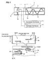
- Fig. 2 is an entire structure of a first embodiment of an image forming device to which the present invention is applied.
- the image forming device has, in a casing 21 of the image forming device (refer it to as a device casing, hereinafter), image forming parts 22 (specifically, 22a to 22d) of four colors (in this embodiment, black, yellow, magenta and cyan) are arranged in a transverse direction with a slightly obliquely and upwardly inclined positional relation.
- image forming parts 22 specifically, 22a to 22d
- an intermediate transfer belt 23 is arranged that is circulated and conveyed along the arranging direction of the image forming parts 22 respectively.
- a recording material supply device 24 is arranged in which recording materials are accommodated so as to be supplied.
- a recording material delivering and receiving part 26 is provided in which recording materials on which imaged are formed are delivered and accommodated so that the recording materials from the recording material supply device 24 are delivered to the recording material delivering and receiving part 26 through a vertically extending recording material conveying path 25.
- the image forming parts 22 respectively form, as shown in Figs. 2 and 3 , for instance, toner images for black, yellow, magenta and cyan (an arrangement is not necessarily limited to the above-described order) in order from an upstream side in the circulating direction of the intermediate transfer belt 23.
- Each image forming part 22 includes, for instance, a photosensitive member 31 formed in a drum shape, a charger 32 for previously charging the photosensitive member 31, an exposure device 33 for writing an electrostatic latent image on the photosensitive member 31 charged by the charger 32, a developing device 34 for visualizing the electrostatic latent image on the photosensitive member 31 to a visible image by color toners respectively and a cleaner 35 for cleaning residual toner on the photosensitive member 31.
- the exposure device 33 is provided commonly to the image forming parts 22 respectively to deflect and scan lights from a light source such as a semiconductor laser (not shown in the drawing) of color components by a deflecting mirror 332 in an exposure vessel 331 and guide an optical image to a corresponding exposure position on the photosensitive member 31 through an image forming lens and a mirror not shown in the drawing.
- a light source such as a semiconductor laser (not shown in the drawing) of color components by a deflecting mirror 332 in an exposure vessel 331 and guide an optical image to a corresponding exposure position on the photosensitive member 31 through an image forming lens and a mirror not shown in the drawing.
- the intermediate transfer belt 23 is extended on stretching rolls 41 to 44, and, circulated and moved by, for instance, the stretching roll 41 as a driving roll. Then, on the back surface of the intermediate transfer belt 23 corresponding to each photosensitive member 31, a primary transfer device 51 (for instance, a primary transfer roll) is arranged. A voltage of a reversed polarity to a charged polarity of the toner is applied to the primary transfer device 51 to electro-statically transfer the toner image on the photosensitive member 31 to the intermediate transfer belt 23.
- a primary transfer device 51 for instance, a primary transfer roll
- a secondary transfer device 52 (for instance, a secondary transfer roll) is arranged to secondarily transfer (transfer together) a primary transfer image on the intermediate transfer belt 23 to the recording material.
- an intermediate cleaner 53 is provided for cleaning the residual toner on the intermediate transfer belt 23.
- the intermediate transfer belt 23 employs a resin such as polyimide, polycarbonate, polyester, polypropylene , etc. or various kinds of rubber including a suitable quantity of antistatic agent such as carbon black and is formed so as to have a volume resistivity of 106 to 1014 ⁇ .cm.
- a resin such as polyimide, polycarbonate, polyester, polypropylene , etc. or various kinds of rubber including a suitable quantity of antistatic agent such as carbon black and is formed so as to have a volume resistivity of 106 to 1014 ⁇ .cm.
- the recording materials supplied by a feeder 61 of the recording material supply device 24 are conveyed by the suitable number of conveying rolls (not shown in the drawing) in the recording material conveying path 25, aligned by an alignment roll 62, then, pass through the secondary transfer part of the secondary transfer device 52 to, for instance, heat, pressurize and fix a toner image to be fixed by a fixing device 66, and then, are delivered and received by the recording material delivering and receiving part 26 through a delivery roll 67.
- reference numeral 38 designates a developer accommodating vessel (toner cartridge) for supplying new developer (in this embodiment, toner) to the developing device 34 of each image forming part 22 (22a to 22d).
- the photosensitive member 31 is formed as a process cartridge having the charger 32 and the cleaner 35 formed integrally therewith.
- This process cartridge is detachably attached to the device casing 21 to form a part of the image forming part 22 including color components respectively.
- the charger 32 includes a charging vessel 321 having an opening in a part opposed to the photosensitive member 31.
- a charging roll 322 is arranged that comes into contact with or comes close to the surface of the photosensitive member 31.
- the cleaner 35 has a cleaning vessel 351 has an opening in a part opposed to the photosensitive member 31.
- a cleaning blade 352 is provided that is made of an elastic scraping plate in contact with the photosensitive member 31.
- an elastic seal material 353 is provided that comes into contact with the photosensitive member 31.
- a leveling and conveying member 354 is provided that levels a residual material such as the toner scraped out by the cleaning blade 352 along the longitudinal direction.
- the developing device 34 is attached to the device casing 21 side separately from the process cartridge.
- the developing device 34 includes a developing vessel 341 that has an opening opposed to the photosensitive member 31 and in which the developer including at least the toner is accommodated.
- a developer holder 342 is arranged that can convey the developer to a developing area located at a part opposed to the photosensitive member 31.
- a pair of developer agitating and conveying members 343 and 344 are arranged that can circulate, agitate ad convey the developer.
- a developer supply member 345 is provided that can supply the agitated and conveyed developer to the developer holder 342 side. Further, the developer supplied to the developer holder 342 whose layer thickness is regulated to a prescribed layer thickness by a layer thickness regulating member 346 is supplied to the developing area.
- Fig. 4 shows one example of a developer supply system used in this embodiment.
- the developer supply system is formed at a part of the device casing 21 and has a vessel receiving part 100 to which the developer accommodating vessel 38 is detachably attached.
- a reserve tank 110 is arranged in which the developer to be supplied is temporarily stored.
- a discharge port not shown in the drawing is opened that can discharge the developer in the developer accommodating vessel 38 when the developer accommodating vessel 38 is attached to the vessel receiving art 100.
- a fixed quantity agitating and conveying member 120 is arranged that can supply a fixed quantity of the stored developer to supply a prescribed quantity of the developer to the developing vessel 341 of the developing device 34 through a duct 130 connected to a part of the reserve tank 110 on the basis of concentration information, for instance, the fall of the concentration of the developer.
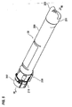
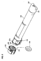
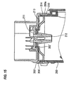
- the developer accommodating vessel 38 includes, as shown in Figs. 5 to 7 , a long tubular vessel main body 200 with both ends opened that is formed with a synthetic resin such as ABS, PET or the like by a draw and blow molding process.
- an agitator 205 is arranged as a conveying member capable of agitating the accommodated developer and end part flanges 201 and 202 as cover members are arranged in both the ends of the vessel main body 200.
- an opening 204 closed by the end part flange 202 is used as a developer supply port to which the developer can be supplied.
- a gripping handle 203 is provided in one end part flange 201.
- a part 210 to be fitted made of a recessed part with a bottom is formed to which an end tubular part 200a of the vessel main body 200 is detachably fitted.
- the part 210 to be fitted includes a bottom wall 213 through which a rotating shaft of the agitator 205 passes and a peripheral wall 214 for surrounding the periphery of the agitator 205.
- the bottom wall 213 of the part 210 to be fitted includes a rotor 211 to which a driving shaft of an external driving source not shown in the drawing is connected.
- a hook part 212 is provided as a coupling member on which a rotating shaft part 205a of the agitator 205 is hooked and supported.
- 216 designates a non-volatile memory as a use history managing memory attached to a suitable part of the vessel main body 200 and is connected to communicated with a controller not shown in the drawing when the developer accommodating vessel 38 is attached to the vessel receiving part 100 to record the use history of the developer accommodating vessel 38.
- a seal member 300 is provided between the end part flange 202 and the vessel main body 200 for sealing a part between both the members.
- the seal member 300 is held in the part 210 to be fitted of the end part flange 202 in a preceding stage of an attached state that the end part flange 202 is attached to the vessel main body 200. That is, the end part flange 202 is formed in a state before an attachment of holding the seal member 300 in the preceding stage of the attached state.
- the seal member 300 is integrally formed by an elastic material such as polyethylene, polypropylene or the like.
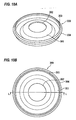
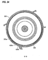
- the seal member includes, as shown in Fig. 10A and 10B , Figs. 11A and 11B and Fig. 12 , an annular main body part 301 that is accommodated in the part 210 to be fitted and through which the rotating shaft of the agitator 205 (in this example, the hook part 212 as the coupling member on which the rotating shaft part 205a of the agitator 205 is supported) passes.
- sealing butting pieces (an inner edge sealing butting piece, an outer edge sealing butting piece) 302 and 303 are formed that abut on the bottom wall 213 of the part 210 to be fitted.
- a sealing butting piece (a peripheral edge sealing butting piece) 304 is formed that abuts on the peripheral wall 214 of the part 210 to be fitted.
- a state is supposed that the seal member 300 is held in the part 210 to be fitted of the end part flange 202 under a condition that the end part flange 202 is in a preceding state of an attachment.
- a1 and a2 are set so as to satisfy a relation of a1 > a2.
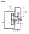
- a positioning mechanism 400 is provided for positioning both the members when the end part flange 202 is attached to an attaching position relative to the end tubular part 200a of the vessel main body 200.
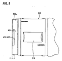
- the positioning mechanism 400 includes a protrusion 410 to be positioned that is formed to protrude in the peripheral wall 214 of the part 210 to be fitted of the end part flange 202 and used to position the end part flange 202 to a predetermined positioning place of the end tubular part 200a of the vessel main body 200 and a positioning protrusion 420 (see Fig. 9 ) that is provided to protrude on the outer peripheral wall of the end tubular part 200a of the vessel main body 200 and abuts on the protrusion 410 to be positioned to position the protrusion 410 to be positioned to the predetermined positioning place.
- the protrusion 410 to be positioned or the positioning protrusion 420 may be respectively formed integrally with the end part flange 202 and the vessel main body 200, or separate members may be fixed thereto.
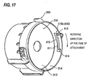
- the protrusion 410 to be positioned is, as shown in Figs. 8 , 16 and 17 , provided in a plurality of places (in this example, two) on the peripheral wall 214 of the part 210 to be fitted of the end part flange 202.
- a first protrusion 410a (410) to be fitted includes, as shown in Figs. 8 and 16 , includes for instance a guide protrusion 411 extending along the rotating direction of the end part flange 202 and a rotation stop protrusion 412 extending from one end side of the guide protrusion 411 to the pushing and pulling direction of the end part flange 202.
- a half part of a rotating direction side at the time of attaching the end part flange 202 extends substantially with the same width dimension, and a side surface of the bottom wall 213 of the part 210 to be fitted as a half part in an opposite side has a guide surface 415 gradually swelling toward an opposite side in the rotating direction at the time of an attachment.
- the rotation stop protrusion 412 is provided in a side end part of the guide protrusion 411 in the rotating direction at the time of the attachment when the end part flange 202 is attached to the vessel main body 200 and extends toward the bottom wall 213 of the part 210 to be fitted from the guide protrusion 411. Then, the side end part of the rotation stop protrusion 412 in the rotation direction at the time of attaching the end part flange 202 is provided with a guide inclined part 416 inclined in a tapered form toward an end side.
- a second protrusion 410b (410) to be fitted includes, as shown in Figs. 8 and 17 , a guide protrusion 411 extending along the rotating direction of the end part flange 202 and a rotation stop protrusion 413 extending toward the pushing and pulling direction of the end part flange 202 from one end side of the guide protrusion 411 and toward an opposite direction to that of the rotation stop protrusion 412 of the first protrusion 410a to be positioned.
- a half part of a rotating direction side at the time of attaching the end part flange 202 extends substantially with the same width dimension, and a side surface of the bottom wall 213 of the part 210 to be fitted as a half part in an opposite side has a guide surface 415 gradually swelling toward an opposite side in the rotating direction at the time of an attachment.
- the rotation stop protrusion 413 is provided in a side end part of the guide protrusion 411 in the rotating direction at the time of the attachment when the end part flange 202 is attached to the vessel main body 200 and extends from the guide protrusion 411 toward a direction separating from the bottom wall 213 of the part 210 to be fitted.
- the second protrusion 410b to be fitted includes a butting protrusion 414 extending toward the pushing and pulling direction of the end part flange 202 from an end part of the guide protrusion 411 opposite to the rotation stop protrusion 413 and in the same direction as that of the rotation stop protrusion 413.
- a plurality of positioning protrusions (in this example, two) are provided correspondingly to the plurality of protrusions 410 (410a, 410b) to be fitted.
- a first positioning protrusion 420a (420) includes, as shown in Figs. 9 and , a positioning protrusion 421 extending along the direction of the circumference of the end tubular part 200a of the vessel main body 200.
- the positioning protrusion 421 includes a stop wall 422 that abuts on the guide protrusion 411 and the rotation stop protrusion 412 of the first protrusion 410a (410) to be fitted to be stopped, and further includes a guide surface 423 along the guide surface 415 of the first protrusion 410a to be fitted.
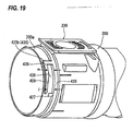
- a second positioning protrusion 420b(420) includes, as shown in Figs. 9 and 19 , a positioning partition wall 426 protruding substantially in an L shape from a stepped annular part 425 formed in an annular shape along the periphery of the end tubular part 200a. In the opening side of the positioning partition wall 426, a separate partition wall 427 is provided that is separated with an opening remaining in a part.
- a partition area 428 surrounded by the stepped annular part 425, the positioning partition wall 426 and the separate partition wall 427 is set as an accommodating area of the second protrusion 410b to be fitted, and a peripheral wall for surrounding the partition area 428 is allowed to function as the stop wall 422 on which the guide protrusion 411, the rotation stop protrusion 413 and the butting protrusion 414 abut to be stopped.
- a guide surface 423 is provided along a guide surface 415 of the second protrusion 410b to be fitted.
- a partition area width j located in an opposite side to a rotating direction side is ensured to be wider than a partition area width m located in the rotating direction side at the time of attaching the end part flange 202.
- a dimension between a surface to be positioned of the guide protrusion 411 of the protrusion 410 to be positioned of the part 210 to be fitted of the end part flange 202 and the bottom wall 213 of the part 210 to be fitted is set to b.
- a dimension from an end of the end tubular part 200a of the vessel main body 200 to a positioning surface of the positioning protrusion 420 corresponding to the surface to be positioned of the guide protrusion 411 of the protrusion 410 to be positioned is set to c.
- the second positioning protrusion 420b(420) forms the partition area 428, however, the present invention is not limited thereto.
- a selection may be suitably made, for instance, the separate partition wall 427 may be removed or the positioning partition wall 426 may be separated from the stepped annular part 425.
- the seal member 300 is held in the part 210 to be fitted of the end part flange 202.
- the inner edge sealing butting piece 302 of the seal member 300 is arranged to come into contact with the bottom wall 213 of the part 210 to be fitted.
- the outer edge sealing butting piece 303 of the seal member 300 is arranged so as not to come into contact with the bottom wall 213 of the part 210 to be fitted.
- the peripheral edge sealing butting piece 304 of the seal member 300 is arranged to come into contact with the peripheral wall 214 of the part 210 to be fitted.
- the outer edge sealing butting piece 303 of the seal member 300 does not come into contact with the bottom wall 213 of the part 210 to be fitted, even when the seal member 300 is held for a long period in the state before an attachment, the outer edge sealing butting piece 303 is not elastically deformed.
- a deterioration of a form such as a state that the outer edge sealing butting piece 303 is deformed is not observed as compared with a case that, for instance, the outer edge sealing butting piece 303 is stored for a long period under a state that the outer edge sealing butting piece 303 is elastically deformed.
- the seal member 300 in a state before the attachment is held in the part 210 to be fitted of the end part flange 202.
- the protrusion 410 to be positioned of the positioning mechanism 400 functions as a stopper for preventing the seal member 300 from slipping out.
- the dimensional relation a1 and a2 (see Fig. 11 ) between the inner edge sealing butting piece 302 and the outer edge sealing butting piece 303 of the seal member 300 and the dimensions b and c (see Figs. 8 and 9 ) of the protrusion 410 to be positioned and the positioning protrusion 420 satisfy relations of a1 > b-c, a2 >b-c and a1 > a2 at this time.
- 'b -c' means a distance from the bottom wall 213 of the part 210 to be fitted of the end part flange 202 to the position of the end tubular part 200a of the vessel main body 200, and the seal member 300 held by the part 210 to be fitted is pressed to 'b-c' by the end tubular part 200a of the vessel main body 200. Therefore, under a state that the inner edge sealing butting piece 302 having the dimension of a1 and the outer edge sealing butting piece 303 having the dimension a2 in the state before the attachment are elastically deformed to 'b-c', the inner and outer sealing butting pieces 302 and 303 are arranged to come into contact with the bottom wall 213 of the part 210 to be fitted.
- a seal member 300' will be used as a comparative embodiment in place of the seal member 300 used in this embodiment to describe a state of the seal member 300' before an attachment and the attached state of the seal member 300' in a state of an attachment.
- the seal member 300' includes, as shown in Figs. 14A and 14B , an annular main body part 301' accommodated in the part 210 to be fitted of the end part flange 202.
- an inner edge sealing butting piece 302' is provided that elastically comes into contact with the bottom wall 213 of the part 210 to be fitted.
- a protruding piece 303' (rib) is provided that pushes to an interior of the part 210 to be fitted.
- a peripheral edge sealing abutting piece 304' is provided that elastically comes into contact with the peripheral wall 214 of the part 210 to be fitted.
- the dimensional relation between the inner edge sealing butting piece 302' and the protruding piece 303' of the seal member 300' is respectively set to a1 and a2 like the first embodiment (however, the protruding piece 303' is functionally different from the outer edge sealing butting piece 303 of the first embodiment, however, the dimensional relation of the protruding piece 303' is allowed to correspond to that of the outer edge sealing butting piece 303 as shown in Fig. 11 ) and the dimensional relation between the protrusion 410 to be fitted and the positioning protrusion 420 is respectively set to b and c (see Figs. 8 and 9 ), relations of a1 > b-c, a2 ⁇ b - c, and a1 > a2 at this time are allowed to be satisfied.
- the seal member 300' is held in the part 210 to be fitted of the end part flange 202.
- a dimensional relation of a1 and a2 between the inner edge sealing butting piece 302' and the protruding piece 303' of the seal member 300' is set to a1 > a2
- the inner edge sealing butting piece 302' of the seal member 300' is arranged to come into contact with the bottom wall 213 of the part 210 to be fitted.
- the protruding piece 303' of the seal member 300' is arranged so as not to come into contact with the bottom wall 213 of the part 210 to be fitted.
- the peripheral edge sealing butting piece 304' of the seal member 300' is arranged to come into contact with the peripheral wall 214 of the part 210 to be fitted.
- the attached state of the seal member 300' before the attachment is substantially the same as that of the embodiment.
- dimensional relations (a1, a2, b, c) of the seal member 300' are respectively the same as those described above.
- 'b -c' means a distance from the bottom wall 213 of the part 210 to be fitted of the end part flange 202 to the position of the end tubular part 200a of the vessel main body 200, and the seal member 300' held by the part 210 to be fitted is pressed to 'b-c' by the end tubular part 200a of the vessel main body 200.
- the inner edge sealing butting piece 302' having the dimension of a1 in the state before the attachment is elastically deformed to 'b-c', the inner edge sealing butting piece 302' is arranged to come into contact with the bottom wall 213 of the part 210 to be fitted.
- the protruding piece 303' of the seal member 300' satisfies the relation of a2 ⁇ b-c, the protruding piece 303' is arranged so as not to come into contact with the bottom wall 213 of the part 210 to be fitted, or to come close to the bottom wall 213 in such a manner as to come into contact therewith, however, is not elastically deformed.
- the protruding piece 303' is arranged to elastically come into contact with the bottom wall 213 of the part 210 to be fitted.
- a sealing part is not obtained in the part of the protruding piece 303' and a sliding resistance due to a contact cannot be obtained between the protruding piece 303' and the bottom wall 213 of the part 210 to be fitted.
- the peripheral edge sealing butting piece 304' is arranged to elastically come into contact with the peripheral wall 214 of the part 210 to be fitted.
- the protruding piece 303' does not serve like the sealing butting piece 303 of the first embodiment, when a user erroneously rotates the attached end part flange 202, the sliding resistance by the sealing butting pieces 302' and 304' act, however, the sliding resistance by the protruding piece 303' is not obtained. Therefore, as compared with the first embodiment, there is more fear that the end part flange 202 is erroneously rotated and the end part flange 202 is erroneously opened.
- the part 210 to be fitted of the end part flange 202 may be pushed in to the end tubular part 200a of the vessel main body 200, and then, the end part flange 202 may be rotated in a prescribed direction.
- the end part flange 202 is rotated by a prescribed amount, as shown in Fig.
- the end part flange 202 is positioned to the end tubular part 200a of the vessel main body 200 by the positioning mechanism 400 under a state that the end part flange 202 is prevented from slipping out and rotating, so that the end part flange 202 is attached to the end tubular part 200a of the vessel main body 200.
- a first positioning element (the first protrusion 410a to be positioned + the first positioning protrusion 420a) moves from a state shown in Fig. 21 to a state shown in Fig. 23 to position the first protrusion 410a to be positioned to the first positioning protrusion 420a.
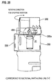
- a second positioning element (the second protrusion 410b to be positioned + the second positioning protrusion 420b) moves from a state shown in Fig. 22 to a state shown in Fig. 24 to position the second protrusion 410b to be positioned to the second positioning protrusion 420b.
- the first protrusion 410a to be positioned is positioned by the first positioning protrusion 420a (see Fig. 18 ).
- the guide protrusion 411 of the first protrusion 410a to be positioned abuts on the stop wall 422 of the positioning protrusion 421 of the first positioning protrusion 420a to be stopped.
- the rotation stop protrusion 412 of the first protrusion 410a to be positioned abuts on the end part of the positioning protrusion 421 to be stopped.
- a preventing force for stopping the rotation can be received by the rotation stop protrusion 412 when the end flange part 202 is rotated.
- the contact area of the rotation stop protrusion 412 and the end part of the positioning protrusion 421 of the first positioning protrusion 420a is ensured to be wider, the preventing force for stopping the rotation at the time of rotating the end part flange 202 is the more increased.
- the preventing force for stopping the rotation at the time of rotating the end part flange 202 can be also received by the guide surface 415 of the guide protrusion 411 of the first protrusion 410a to be positioned, the preventing force for stopping the rotation of the end part flange 202 is more preferably increased.
- the second protrusion 410b to be positioned is positioned by the second positioning protrusion 420b (see Fig. 19 ).
- the second protrusion 410b to be positioned is accommodated in the partition area 428 of the second positioning protrusion 420b.
- the guide protrusion 411 of the second protrusion 410b to be positioned is stopped by the stop wall 422 of the positioning partition wall 426 of the second positioning protrusion 420b. Further, the rotation stop protrusion 413 of the second protrusion 410b to be positioned abuts on the stop wall 422 at the end part of the positioning partition wall 426 to be stopped.
- a preventing force for stopping the rotation can be received by the rotation stop protrusion 413 when the end flange part 202 is rotated.
- the contact area of the rotation stop protrusion 413 and the stop wall 422 of the positioning partition wall 426 of the second positioning protrusion 420b is ensured to be wider than that of the comparative example, the preventing force for stopping the rotation at the time of rotating the end part flange 202 is increased more than that of the comparative example.
- the rotating torque resistance of the end part flange 202 is preferably more distributed.
- the second protrusion 410b to be positioned since the second protrusion 410b to be positioned includes the butting protrusion 414 abutting on the stepped annular part 425 separately from the rotation stop protrusion 413, the second protrusion 410b to be positioned does not collapse nor move in the partition area 248 of the second positioning protrusion 420b. Thus, an attached state of the end part flange 202 is not deteriorated.
- the partition area width j located in an opposite side to the partition area width m is ensured to be wider than the partition area width m located in the rotating direction side at the time of attaching the end part flange 202, the second protrusion 410b to be positioned preferably easily enters the partition area 428 and moves to the narrow area of the partition area 428 to be readily positioned.
- the first protrusion 410a to be positioned and the second protrusion 410b to be positioned respectively have the rotation stop protrusions 412 and 413 extending in the opposite directions to each other relative to the pushing and pulling direction of the end part flange 202.
- the rotation stop protrusion 412 of the one protrusion 410 (for instance 410a) to be positioned is directly stopped by the stop wall 422 of for instance, the one positioning protrusion 420 (for instance 420a).
- the end flange part 202 when the end part flange 202 tries to be rotated to the prescribed rotating direction, the end flange part 202 is inclined relative to the vessel main body 200 on the above-described rotation stop part as a supporting point. Under a state that the end part flange 202 is inclined, the rotation stop protrusion 413 of the other protrusion 410 (for instance, 410b) to be positioned is stopped by the stop wall 422 of the other positioning protrusion 420 (for instance, 420b).
- the sliding resistance due to the contact between the positioning protrusion 420 (420a, 420b) and the protrusion 410 (410a, 410b) to be positioned is increased, so that the end part flange 202 is hardly slipped off and rotated relative to the vessel main body 200.
- the guide protrusion 411 of the first protrusion 410a to be positioned is stopped by the positioning protrusion 421 of the first positioning protrusion 420a. Further, the guide protrusion 411 of the second protrusion 410b to be positioned is stopped by the positioning partition wall 426 of the second positioning protrusion 420b. Thus, the movement of the end part flange 202 to the pulling out direction is prevented.
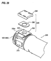
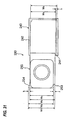
- a discharging opening 220 is opened on a peripheral wall of the vessel main body 200 located near the end part flange 202.
- a shutter 230 is provided as an opening and closing mechanism that opens and closes the opening 220.
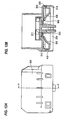
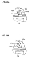
- the shutter 230 includes, as shown in Figs. 29 and 30A , a closing cover 240 for closing the discharging opening 220 and a cover holding frame 250 that holds the closing cover 240 so as to freely move along an opening and closing direction.
- the closing cover 240 includes, as shown in Fig. 30B , a flat plate shaped cover main body 241 having a substantially rectangular form that has at least a larger area than that of the discharging opening 220.
- Side wall parts 242 are formed correspondingly to three sides except one direction in the opening and closing direction of the cover main body 241.
- the suitable number in this example, two arms spaced in the opening and closing direction respectively in one side
- holding arms 243 are formed that protrude inward and embrace and hold the cover holding frame 250.
- a hook pawl 244 as a stopper part is formed on the surface of the cover main body 241 in the cover holding frame 250 side.
- an elastic seal material 245 is stuck that elastically comes into contact with the cover holding frame 250.
- hole parts 246 are provided in the parts of the cover main body 241 corresponding to the holding arms 243.
- the closing cover 240 holds both the side edges of the cover holding frame 250 by three points including the two holding arms 243 and the cover main body 241 located between the holding arms 243 and moves along both the side edges of the cover holding frame 250 in a stable way.
- the cover holding frame 250 includes, as shown in Fig. 30A , a flat plate shaped frame main body 251 having a substantially rectangular form. On a part of the frame main body 251 corresponding to the discharging opening 220, a through hole 252 is opened. Further, in one corner part of an end edge of the frame main body 251 in the closing direction of the closing cover 240, a cut-out stop part 253 is formed. In an opposite corner part of the end edge of the frame main body 251, a position regulating protrusion 254 is formed that protrudes in the direction of width orthogonal to the opening and closing direction.
- a dimension between both side edges in the direction of width of the cover holding frame 250 is set to be slightly narrower than a dimension between both the side wall parts 242 in the direction of width of the closing cover 240.
- a protruding dimension k of the position regulating protrusion 254 from reference positions of both the side edges in the direction of width of the cover holding frame 250 is set to be larger than the dimension of the stop part 253 in the direction of width.
- reference numeral 260 designates a seal plate made of, for instance, an elastic rubber that is provided between the closing cover 240 and the cover holding frame 250 to seal a part between them, and is for instance, fixed to the frame main body 251.
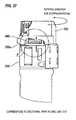
- a dimensional relations for opening and closing the shutter 230 (the closing cover 240, the cover holding frame 250) is summarized as shown in Fig. 31 .
- w1 to w6 and f, h and k designate below-described dimensions.
- the stop length f (w1 - w2) of the stop part 253 is examined.
- f needs to be larger than a space of w5 - w2, that is, the condition of f - (w5 - w2) > 0 or f > w5 - w2 is necessary.
- k needs to be larger than a space of w5 - w3, that is, the condition of k - (w5 - w3) > 0 or k > w5 - w3 is necessary.
- h needs to be larger than a space of w6 - w1, that is, the condition of h - (w6 -w1) > 0 or h > w6 -w1 is necessary.
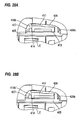
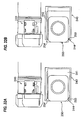
- the shutter 230 operates over operating processes as shown in Figs. 32 and 33 .
- the side wall part 242 located in the opening and closing direction of the closing cover 240 abuts on one end part in the opening and closing direction of the cover holding frame 250.
- the side wall part 242 in the direction of width of the closing cover 240 is located at a position abutting on the end of the position regulating protrusion 254 of the cover holding frame 250.
- the closing cover 240 moves from the state shown in Fig. 32A to an opening direction, the closing cover 240 moves by maintaining a state that a position is regulated by the position regulating protrusion 254 and the hook pawl 244 of the closing cover 240 abuts on the stop part 253 (see Fig. 32B ).
- the closing cover 240 is restrained from moving at a position before an opening operation is started, the shutter 230 is locked relative to the opening and closing direction.
- the side wall part 242 in the direction of width of the closing cover 240 moves to a position passing the position regulating protrusion 254 of the cover holding frame 250.
- the closing cover 240 is permitted to move to come close to the side edge in the direction of width of the cover holding frame 250 relative to the direction of width (an intersecting direction) orthogonal to the opening and closing direction.
- the closing cover 240 moves along the direction of width until the one side wall part 242 in the direction of width abuts on the reference position of the side edge in the direction of width of the cover holding fame 250.
- the hook pawl 244 of the closing cover 240 moves to a position where the hook pawl 244 does not come into contact with the stop part 253 of the cover holding frame 250, the hook pawl 244 can move in the opening and closing direction of the closing cover 240 to release the restrained state of the closing cover 240 by the stop part 253 and the hook pawl 244. That is, the locked state of the shutter 230 relative to the opening and closing direction is unlocked, so that the shutter can move in the opening and closing direction.
- An image forming device uses a developer accommodating vessel substantially the same as the developer accommodating vessel 38 used in the first embodiment, however, uses, differently from the first embodiment, the seal member 300' according to the comparative embodiment shown in Figs. 14 and 15 in place of the seal member 300 used in the first embodiment, and employs a positioning mechanism 400 having the same structure as that of the first embodiment.
- seal member 300' a form is shown that uses the seal member 300' according to the comparative embodiment, however, the present invention is not limited thereto. It is to be understood that a seal member such as a seal plate of felt or rubber may be used between the end part flange 202 and the end tubular part 200a of the vessel main body 200 or another sealing structure may be used without using such a seal member.
- a seal member such as a seal plate of felt or rubber may be used between the end part flange 202 and the end tubular part 200a of the vessel main body 200 or another sealing structure may be used without using such a seal member.
- the developer accommodating vessel (the toner cartridge) is exemplified and explained that is detachably attached to the image forming device of the electro-photographic system and accommodates the developer composed of powder type toner used in the developing device
- the present invention may be applied to all accommodating vessels for accommodating an image forming material supplied to the image forming device.
- the present invention may be applied to the developer accommodating vessel for accommodating liquid developer.
- the present invention may be applied to an ink accommodating vessel for accommodating ink supplied to an ink jet type image forming device.
Landscapes
- Physics & Mathematics (AREA)
- General Physics & Mathematics (AREA)
- Dry Development In Electrophotography (AREA)
- Electrophotography Configuration And Component (AREA)
Claims (2)
- Aufnahmegefäß, lösbar befestigt an einem Gefäßaufnahmeabschnitt des Gehäuses einer Bilderstellungsvorrichtung für die Aufnahme eines Bilderstellungsmaterials, das Aufnahmegefäß umfassend
einen Gefäßhauptteil (1), enthaltend einen röhrenförmigen Abschnitt (1a) mit einer in einem Abschnitt davon geöffneten Öffnung;
ein Abdeckelement (3), enthaltend einen angebauten Abschnitt (3a) mit einer in einem Abschnitt davon geöffneten Öffnung, wobei
der röhrenförmige Abschnitt (1a) und der angebaute Abschnitt (3a) einen Raum zur Aufnahme des Bilderstellungsmaterials bilden,
der angebaute Abschnitt (3a) sich gegenüber dem röhrenförmigen Abschnitt (1a) in einer vorbestimmten Drehrichtung dreht, so dass das Abdeckelement (3) sich in eine befestigende Stellung bewegt, und
der angebaute Abschnitt (3a) sich gegenüber dem röhrenförmigen Abschnitt (1a) entgegen der vorbestimmten Drehrichtung dreht, so dass das Abdeckelement (3) sich in eine lösende Stellung bewegt; wobei das Aufnahmegefäß dadurch gekennzeichnet ist, dass es zudem umfasst
einen Platzierungsmechanismus (400), welcher den röhrenförmigen Abschnitt des Gefäßhauptteils (1) und den angebauten Abschnitt des Abdeckelements (3) platziert,
wobei
der Platzierungsmechanismus (400) eine Mehrzahl erste Ausbuchtungen (4, 410) und eine Mehrzahl zweite Ausbuchtungen (5, 420) aufweist,
wobei
die Mehrzahl erste Ausbuchtungen (4, 410) auf dem röhrenförmigen Abschnitt des Gefäßhauptteils (1), bereitgestellt sind,
jede erste Ausbuchtung (410) eine erste Führungsausbuchtung (11, 411) aufweist, die vom röhrenförmigen Abschnitt hervorragt und sich in die vorbestimmte Drehrichtung erstreckt, und
die erste Führungsausbuchtung (11, 411) den angebauten Abschnitt des Abdeckelements (3) führt, das sich gegenüber dem röhrenförmigen Abschnitt des Gefäßhauptteils (1) dreht,
wobei
die Mehrzahl zweite Ausbuchtungen (5, 420) auf dem angebauten Abschnitt des Abdeckelements (3) bereitgestellt sind,
jede zweite Ausbuchtung (5, 420) eine zweite Führungsausbuchtung aufweist, die vom angebauten Abschnitt (3a) hervorragt und sich in die vorbestimmte Drehrichtung erstreckt,
die zweite Führungsausbuchtung mit einer der ersten Führungsausbuchtungen (4, 410) zusammenkommt, um den dem röhrenförmigen Abschnitt des Gefäßhauptteils (1) zu führen, der sich gegenüber dem angebauten Abschnitt des Abdeckelements (3) dreht, und
die zweite Führungsausbuchtung eine Bewegung des Gefäßhauptteils (1) vom Abdeckelement (3) in eine Richtung begrenzt, die die vorbestimmte Drehrichtung schneidet, in einem Zustand, in dem das Abdeckelement (3) in der befestigenden Stellung platziert ist, und
wobei
eine erste Drehstoppausbuchtung (12) sich von mindestens einer der ersten Ausbuchtungen (4, 410) erstreckt in eine Richtung, die die vorbestimmte Drehrichtung schneidet, und verhindert, dass das Abdeckelement (3) sich in die vorbestimmte Richtung dreht,
eine zweite Drehstoppausbuchtung (13) sich von mindestens einer der ersten Ausbuchtungen (4, 410) erstreckt in eine weitere Richtung, die die vorbestimmte Drehrichtung schneidet, und verhindert, dass der Gefäßhauptteil (1) sich entgegen die vorbestimmte Richtung dreht, wenn der Gefäßhauptteil (1) vom Abdeckelement (3) gelöst ist, und
die erste Drehstoppausbuchtung (12) und die zweite Drehstoppausbuchtung (13) sich in entgegen gesetzte Richtungen erstrecken. - Bilderzeugungsvorrichtung, umfassend
ein Gehäuse (21) in dem der gefäßaufnehmende Abschnitt gebildet wird; und
das Aufnahmegefäß gemäß Anspruch 1, wobei
das Aufnahmegefäß lösbar mit dem gefäßaufnehmenden Abschnitt der Bilderzeugungsvorrichtung verbunden ist, und
das Aufnahmegefäß das Bilderstellungsmaterial aufnimmt.
Applications Claiming Priority (2)
| Application Number | Priority Date | Filing Date | Title |
|---|---|---|---|
| JP2008248935A JP4600560B2 (ja) | 2008-09-26 | 2008-09-26 | 収容容器及びこれを用いた画像形成装置 |
| EP09163179A EP2169475B1 (de) | 2008-09-26 | 2009-06-18 | Aufnahmegefäß und Bilderstellungsvorrichtung, die dieses Gefäß einsetzt |
Related Parent Applications (1)
| Application Number | Title | Priority Date | Filing Date |
|---|---|---|---|
| EP09163179.6 Division | 2009-06-18 |
Publications (2)
| Publication Number | Publication Date |
|---|---|
| EP2372468A1 EP2372468A1 (de) | 2011-10-05 |
| EP2372468B1 true EP2372468B1 (de) | 2013-08-07 |
Family
ID=41581471
Family Applications (2)
| Application Number | Title | Priority Date | Filing Date |
|---|---|---|---|
| EP09163179A Active EP2169475B1 (de) | 2008-09-26 | 2009-06-18 | Aufnahmegefäß und Bilderstellungsvorrichtung, die dieses Gefäß einsetzt |
| EP11170530.7A Active EP2372468B1 (de) | 2008-09-26 | 2009-06-18 | Aufnahmegefäß und Bilderstellungsvorrichtung, die dieses Gefäß einsetzt |
Family Applications Before (1)
| Application Number | Title | Priority Date | Filing Date |
|---|---|---|---|
| EP09163179A Active EP2169475B1 (de) | 2008-09-26 | 2009-06-18 | Aufnahmegefäß und Bilderstellungsvorrichtung, die dieses Gefäß einsetzt |
Country Status (7)
| Country | Link |
|---|---|
| US (2) | US7937029B2 (de) |
| EP (2) | EP2169475B1 (de) |
| JP (1) | JP4600560B2 (de) |
| KR (1) | KR101031557B1 (de) |
| CN (2) | CN101685284B (de) |
| AT (1) | ATE523815T1 (de) |
| AU (2) | AU2009201442B2 (de) |
Families Citing this family (12)
| Publication number | Priority date | Publication date | Assignee | Title |
|---|---|---|---|---|
| USD630678S1 (en) * | 2009-09-17 | 2011-01-11 | Fuji Xerox Co., Ltd. | Toner cartridge |
| USD636017S1 (en) * | 2009-09-17 | 2011-04-12 | Fuji Xerox Co., Ltd. | Toner cartridge |
| USD630243S1 (en) * | 2009-09-17 | 2011-01-04 | Fuji Xerox Co., Ltd. | Toner cartridge |
| USD630244S1 (en) * | 2009-09-17 | 2011-01-04 | Fuji Xerox Co., Ltd. | Toner cartridge |
| EP3770691A1 (de) | 2010-06-11 | 2021-01-27 | Ricoh Company, Ltd. | Informationsspeichervorrichtung, entnehmbare vorrichtung, entwicklerbehälter und bilderzeugungsvorrichtung |
| CA2830876C (en) * | 2011-03-30 | 2017-06-27 | Ricoh Company, Ltd. | Powder storage container and image forming apparatus |
| JP5853404B2 (ja) * | 2011-04-25 | 2016-02-09 | 株式会社リコー | 粉体収納容器および画像形成装置 |
| JP5110219B1 (ja) * | 2012-02-21 | 2012-12-26 | 富士ゼロックス株式会社 | 粉体容器および画像形成装置 |
| JP2013242474A (ja) * | 2012-05-22 | 2013-12-05 | Fuji Xerox Co Ltd | 現像剤容器の梱包構造 |
| JP6156066B2 (ja) | 2013-10-31 | 2017-07-05 | ブラザー工業株式会社 | カートリッジ |
| JP6665597B2 (ja) * | 2016-03-08 | 2020-03-13 | 富士ゼロックス株式会社 | 現像剤の収容容器および画像形成装置 |
| EP3762237B1 (de) * | 2018-08-30 | 2025-04-02 | Hewlett-Packard Development Company, L.P. | Nachfüllen von druckmaterialien |
Family Cites Families (23)
| Publication number | Priority date | Publication date | Assignee | Title |
|---|---|---|---|---|
| JPS537941Y2 (de) * | 1971-08-02 | 1978-02-28 | ||
| JPS537941A (en) | 1976-07-09 | 1978-01-24 | Morio Watanabe | Structure of multiilayer hollow window |
| HUT41715A (en) | 1984-12-28 | 1987-05-28 | Monsanto Co | Process for preparing n-substituted alpha-aminoacids and derivatives thereof |
| JPH0454110Y2 (de) * | 1985-03-27 | 1992-12-18 | ||
| JP2967619B2 (ja) | 1991-07-26 | 1999-10-25 | 日本電気株式会社 | カラー固体撮像装置 |
| US5339596A (en) * | 1992-11-04 | 1994-08-23 | Cohen Zev B | Toner cartridge recharging tool |
| US5398849A (en) * | 1993-06-28 | 1995-03-21 | Nu-Kote International | Cartridge with slide mechanism for dispensing toner |
| JP3480075B2 (ja) * | 1994-09-22 | 2003-12-15 | セイコーエプソン株式会社 | トナー補給用カートリッジ |
| JPH09211947A (ja) * | 1996-01-31 | 1997-08-15 | Konica Corp | 現像剤収納容器及び現像剤供給装置 |
| JP3555918B2 (ja) * | 1997-01-17 | 2004-08-18 | 株式会社資生堂 | 蓋体の係合構造 |
| JP2000010390A (ja) | 1998-06-24 | 2000-01-14 | Sharp Corp | 現像剤収容容器 |
| US6259877B1 (en) * | 2000-02-18 | 2001-07-10 | Toshiba Tec Kabushiki Kaisha | Toner cartridge and toner supply device |
| EP1233311B1 (de) * | 2001-02-19 | 2012-08-29 | Canon Kabushiki Kaisha | Tonerzufuhrbehälter |
| ES2369115T3 (es) * | 2001-02-19 | 2011-11-25 | Canon Kabushiki Kaisha | Contenedor para suministro de toner y sistema para suministro de toner. |
| US6990301B2 (en) | 2001-02-19 | 2006-01-24 | Canon Kabushiki Kaisha | Sealing member, toner accommodating container and image forming apparatus |
| JP2002351199A (ja) | 2001-05-22 | 2002-12-04 | Sharp Corp | トナー補給ボトル |
| JP4167589B2 (ja) * | 2003-12-17 | 2008-10-15 | 株式会社リコー | 収納容器、トナー収納容器及び画像形成装置 |
| KR100727943B1 (ko) * | 2005-06-27 | 2007-06-14 | 삼성전자주식회사 | 제어보드를 내장한 토너카트리지 및 이를 채용한전자사진방식 화상형성장치 |
| KR100756044B1 (ko) * | 2005-08-29 | 2007-09-07 | 삼성전자주식회사 | 현상제통과 현상제 공급장치 및 이를 가지는 화상형성장치 |
| US7460819B2 (en) * | 2005-12-21 | 2008-12-02 | Kabushiki Kaisha Toshiba | Toner cartridge and image forming apparatus |
| JP4566147B2 (ja) * | 2006-03-06 | 2010-10-20 | シャープ株式会社 | トナー容器及びトナー充填方法 |
| JP2007240663A (ja) | 2006-03-06 | 2007-09-20 | Canon Inc | 撮像装置及び撮像装置におけるクリーニング方法 |
| US7548715B2 (en) * | 2007-04-26 | 2009-06-16 | General Plastic Industrial Co., Ltd. | Container for toner cartridge |
-
2008
- 2008-09-26 JP JP2008248935A patent/JP4600560B2/ja active Active
-
2009
- 2009-04-13 US US12/422,729 patent/US7937029B2/en not_active Ceased
- 2009-04-13 KR KR1020090031662A patent/KR101031557B1/ko active Active
- 2009-04-14 AU AU2009201442A patent/AU2009201442B2/en active Active
- 2009-04-17 CN CN2009101355170A patent/CN101685284B/zh active Active
- 2009-04-17 CN CN201110350681.0A patent/CN102354091B/zh active Active
- 2009-06-18 EP EP09163179A patent/EP2169475B1/de active Active
- 2009-06-18 AT AT09163179T patent/ATE523815T1/de not_active IP Right Cessation
- 2009-06-18 EP EP11170530.7A patent/EP2372468B1/de active Active
-
2011
- 2011-05-23 AU AU2011202382A patent/AU2011202382B2/en active Active
-
2012
- 2012-04-19 US US13/451,159 patent/USRE44172E1/en active Active
Also Published As
| Publication number | Publication date |
|---|---|
| EP2372468A1 (de) | 2011-10-05 |
| USRE44172E1 (en) | 2013-04-23 |
| AU2009201442A1 (en) | 2010-04-15 |
| EP2169475B1 (de) | 2011-09-07 |
| EP2169475A1 (de) | 2010-03-31 |
| AU2011202382B2 (en) | 2012-03-15 |
| CN101685284B (zh) | 2012-07-18 |
| KR101031557B1 (ko) | 2011-04-27 |
| US7937029B2 (en) | 2011-05-03 |
| JP4600560B2 (ja) | 2010-12-15 |
| AU2011202382A1 (en) | 2011-06-09 |
| KR20100035572A (ko) | 2010-04-05 |
| CN101685284A (zh) | 2010-03-31 |
| AU2009201442B2 (en) | 2011-02-24 |
| CN102354091A (zh) | 2012-02-15 |
| ATE523815T1 (de) | 2011-09-15 |
| US20100098456A1 (en) | 2010-04-22 |
| JP2010079073A (ja) | 2010-04-08 |
| CN102354091B (zh) | 2015-01-21 |
Similar Documents
| Publication | Publication Date | Title |
|---|---|---|
| EP2372468B1 (de) | Aufnahmegefäß und Bilderstellungsvorrichtung, die dieses Gefäß einsetzt | |
| JP4530029B2 (ja) | 現像剤収容容器及びこれを用いた画像形成装置 | |
| US8483599B2 (en) | Powder container, powder processing apparatus using the same, and powder container controlling method | |
| US8831484B2 (en) | Powder container, powder processing apparatus using the same, and powder container controlling method | |
| US10133233B2 (en) | Toner container configured to be attachable to and detachable from a toner replenishing portion and a waste toner collecting portion | |
| JP4618357B2 (ja) | 収容容器及びこれを用いた画像形成装置 | |
| JP4217920B1 (ja) | 現像剤収容容器及びこれを用いた画像形成装置 | |
| JP4720955B2 (ja) | 収容容器及びこれを用いた画像形成装置 | |
| US8224205B2 (en) | Powder storage container and image forming apparatus using the same | |
| HK1127814B (en) | Developer storage container and image forming apparatus using the same |
Legal Events
| Date | Code | Title | Description |
|---|---|---|---|
| PUAI | Public reference made under article 153(3) epc to a published international application that has entered the european phase |
Free format text: ORIGINAL CODE: 0009012 |
|
| AC | Divisional application: reference to earlier application |
Ref document number: 2169475 Country of ref document: EP Kind code of ref document: P |
|
| AK | Designated contracting states |
Kind code of ref document: A1 Designated state(s): AT BE BG CH CY CZ DE DK EE ES FI FR GB GR HR HU IE IS IT LI LT LU LV MC MK MT NL NO PL PT RO SE SI SK TR |
|
| 17P | Request for examination filed |
Effective date: 20120404 |
|
| RIC1 | Information provided on ipc code assigned before grant |
Ipc: G03G 15/08 20060101AFI20121221BHEP |
|
| GRAJ | Information related to disapproval of communication of intention to grant by the applicant or resumption of examination proceedings by the epo deleted |
Free format text: ORIGINAL CODE: EPIDOSDIGR1 |
|
| GRAP | Despatch of communication of intention to grant a patent |
Free format text: ORIGINAL CODE: EPIDOSNIGR1 |
|
| RIN1 | Information on inventor provided before grant (corrected) |
Inventor name: MURASE, HIROKAZU Inventor name: HIRATA, KEI |
|
| GRAS | Grant fee paid |
Free format text: ORIGINAL CODE: EPIDOSNIGR3 |
|
| GRAA | (expected) grant |
Free format text: ORIGINAL CODE: 0009210 |
|
| AC | Divisional application: reference to earlier application |
Ref document number: 2169475 Country of ref document: EP Kind code of ref document: P |
|
| AK | Designated contracting states |
Kind code of ref document: B1 Designated state(s): AT BE BG CH CY CZ DE DK EE ES FI FR GB GR HR HU IE IS IT LI LT LU LV MC MK MT NL NO PL PT RO SE SI SK TR |
|
| REG | Reference to a national code |
Ref country code: GB Ref legal event code: FG4D |
|
| REG | Reference to a national code |
Ref country code: AT Ref legal event code: REF Ref document number: 626011 Country of ref document: AT Kind code of ref document: T Effective date: 20130815 Ref country code: CH Ref legal event code: EP |
|
| REG | Reference to a national code |
Ref country code: IE Ref legal event code: FG4D |
|
| REG | Reference to a national code |
Ref country code: DE Ref legal event code: R096 Ref document number: 602009017884 Country of ref document: DE Effective date: 20130926 |
|
| REG | Reference to a national code |
Ref country code: AT Ref legal event code: MK05 Ref document number: 626011 Country of ref document: AT Kind code of ref document: T Effective date: 20130807 |
|
| REG | Reference to a national code |
Ref country code: NL Ref legal event code: VDEP Effective date: 20130807 |
|
| REG | Reference to a national code |
Ref country code: LT Ref legal event code: MG4D |
|
| PG25 | Lapsed in a contracting state [announced via postgrant information from national office to epo] |
Ref country code: SE Free format text: LAPSE BECAUSE OF FAILURE TO SUBMIT A TRANSLATION OF THE DESCRIPTION OR TO PAY THE FEE WITHIN THE PRESCRIBED TIME-LIMIT Effective date: 20130807 Ref country code: IS Free format text: LAPSE BECAUSE OF FAILURE TO SUBMIT A TRANSLATION OF THE DESCRIPTION OR TO PAY THE FEE WITHIN THE PRESCRIBED TIME-LIMIT Effective date: 20131207 Ref country code: LT Free format text: LAPSE BECAUSE OF FAILURE TO SUBMIT A TRANSLATION OF THE DESCRIPTION OR TO PAY THE FEE WITHIN THE PRESCRIBED TIME-LIMIT Effective date: 20130807 Ref country code: CY Free format text: LAPSE BECAUSE OF FAILURE TO SUBMIT A TRANSLATION OF THE DESCRIPTION OR TO PAY THE FEE WITHIN THE PRESCRIBED TIME-LIMIT Effective date: 20130619 Ref country code: PT Free format text: LAPSE BECAUSE OF FAILURE TO SUBMIT A TRANSLATION OF THE DESCRIPTION OR TO PAY THE FEE WITHIN THE PRESCRIBED TIME-LIMIT Effective date: 20131209 Ref country code: NO Free format text: LAPSE BECAUSE OF FAILURE TO SUBMIT A TRANSLATION OF THE DESCRIPTION OR TO PAY THE FEE WITHIN THE PRESCRIBED TIME-LIMIT Effective date: 20131107 Ref country code: HR Free format text: LAPSE BECAUSE OF FAILURE TO SUBMIT A TRANSLATION OF THE DESCRIPTION OR TO PAY THE FEE WITHIN THE PRESCRIBED TIME-LIMIT Effective date: 20130807 Ref country code: AT Free format text: LAPSE BECAUSE OF FAILURE TO SUBMIT A TRANSLATION OF THE DESCRIPTION OR TO PAY THE FEE WITHIN THE PRESCRIBED TIME-LIMIT Effective date: 20130807 |
|
| PG25 | Lapsed in a contracting state [announced via postgrant information from national office to epo] |
Ref country code: PL Free format text: LAPSE BECAUSE OF FAILURE TO SUBMIT A TRANSLATION OF THE DESCRIPTION OR TO PAY THE FEE WITHIN THE PRESCRIBED TIME-LIMIT Effective date: 20130807 Ref country code: LV Free format text: LAPSE BECAUSE OF FAILURE TO SUBMIT A TRANSLATION OF THE DESCRIPTION OR TO PAY THE FEE WITHIN THE PRESCRIBED TIME-LIMIT Effective date: 20130807 Ref country code: SI Free format text: LAPSE BECAUSE OF FAILURE TO SUBMIT A TRANSLATION OF THE DESCRIPTION OR TO PAY THE FEE WITHIN THE PRESCRIBED TIME-LIMIT Effective date: 20130807 Ref country code: BE Free format text: LAPSE BECAUSE OF FAILURE TO SUBMIT A TRANSLATION OF THE DESCRIPTION OR TO PAY THE FEE WITHIN THE PRESCRIBED TIME-LIMIT Effective date: 20130807 Ref country code: NL Free format text: LAPSE BECAUSE OF FAILURE TO SUBMIT A TRANSLATION OF THE DESCRIPTION OR TO PAY THE FEE WITHIN THE PRESCRIBED TIME-LIMIT Effective date: 20130807 Ref country code: GR Free format text: LAPSE BECAUSE OF FAILURE TO SUBMIT A TRANSLATION OF THE DESCRIPTION OR TO PAY THE FEE WITHIN THE PRESCRIBED TIME-LIMIT Effective date: 20131108 Ref country code: FI Free format text: LAPSE BECAUSE OF FAILURE TO SUBMIT A TRANSLATION OF THE DESCRIPTION OR TO PAY THE FEE WITHIN THE PRESCRIBED TIME-LIMIT Effective date: 20130807 |
|
| PG25 | Lapsed in a contracting state [announced via postgrant information from national office to epo] |
Ref country code: CY Free format text: LAPSE BECAUSE OF FAILURE TO SUBMIT A TRANSLATION OF THE DESCRIPTION OR TO PAY THE FEE WITHIN THE PRESCRIBED TIME-LIMIT Effective date: 20130807 |
|
| PG25 | Lapsed in a contracting state [announced via postgrant information from national office to epo] |
Ref country code: DK Free format text: LAPSE BECAUSE OF FAILURE TO SUBMIT A TRANSLATION OF THE DESCRIPTION OR TO PAY THE FEE WITHIN THE PRESCRIBED TIME-LIMIT Effective date: 20130807 Ref country code: RO Free format text: LAPSE BECAUSE OF FAILURE TO SUBMIT A TRANSLATION OF THE DESCRIPTION OR TO PAY THE FEE WITHIN THE PRESCRIBED TIME-LIMIT Effective date: 20130807 Ref country code: EE Free format text: LAPSE BECAUSE OF FAILURE TO SUBMIT A TRANSLATION OF THE DESCRIPTION OR TO PAY THE FEE WITHIN THE PRESCRIBED TIME-LIMIT Effective date: 20130807 Ref country code: SK Free format text: LAPSE BECAUSE OF FAILURE TO SUBMIT A TRANSLATION OF THE DESCRIPTION OR TO PAY THE FEE WITHIN THE PRESCRIBED TIME-LIMIT Effective date: 20130807 Ref country code: CZ Free format text: LAPSE BECAUSE OF FAILURE TO SUBMIT A TRANSLATION OF THE DESCRIPTION OR TO PAY THE FEE WITHIN THE PRESCRIBED TIME-LIMIT Effective date: 20130807 |
|
| PG25 | Lapsed in a contracting state [announced via postgrant information from national office to epo] |
Ref country code: IT Free format text: LAPSE BECAUSE OF FAILURE TO SUBMIT A TRANSLATION OF THE DESCRIPTION OR TO PAY THE FEE WITHIN THE PRESCRIBED TIME-LIMIT Effective date: 20130807 Ref country code: ES Free format text: LAPSE BECAUSE OF FAILURE TO SUBMIT A TRANSLATION OF THE DESCRIPTION OR TO PAY THE FEE WITHIN THE PRESCRIBED TIME-LIMIT Effective date: 20130807 |
|
| PLBE | No opposition filed within time limit |
Free format text: ORIGINAL CODE: 0009261 |
|
| STAA | Information on the status of an ep patent application or granted ep patent |
Free format text: STATUS: NO OPPOSITION FILED WITHIN TIME LIMIT |
|
| 26N | No opposition filed |
Effective date: 20140508 |
|
| REG | Reference to a national code |
Ref country code: DE Ref legal event code: R097 Ref document number: 602009017884 Country of ref document: DE Effective date: 20140508 |
|
| PG25 | Lapsed in a contracting state [announced via postgrant information from national office to epo] |
Ref country code: LU Free format text: LAPSE BECAUSE OF FAILURE TO SUBMIT A TRANSLATION OF THE DESCRIPTION OR TO PAY THE FEE WITHIN THE PRESCRIBED TIME-LIMIT Effective date: 20140618 Ref country code: MC Free format text: LAPSE BECAUSE OF FAILURE TO SUBMIT A TRANSLATION OF THE DESCRIPTION OR TO PAY THE FEE WITHIN THE PRESCRIBED TIME-LIMIT Effective date: 20130807 |
|
| REG | Reference to a national code |
Ref country code: CH Ref legal event code: PL |
|
| REG | Reference to a national code |
Ref country code: IE Ref legal event code: MM4A |
|
| PG25 | Lapsed in a contracting state [announced via postgrant information from national office to epo] |
Ref country code: LI Free format text: LAPSE BECAUSE OF NON-PAYMENT OF DUE FEES Effective date: 20140630 Ref country code: IE Free format text: LAPSE BECAUSE OF NON-PAYMENT OF DUE FEES Effective date: 20140618 Ref country code: CH Free format text: LAPSE BECAUSE OF NON-PAYMENT OF DUE FEES Effective date: 20140630 |
|
| PG25 | Lapsed in a contracting state [announced via postgrant information from national office to epo] |
Ref country code: MT Free format text: LAPSE BECAUSE OF FAILURE TO SUBMIT A TRANSLATION OF THE DESCRIPTION OR TO PAY THE FEE WITHIN THE PRESCRIBED TIME-LIMIT Effective date: 20130807 |
|
| REG | Reference to a national code |
Ref country code: FR Ref legal event code: PLFP Year of fee payment: 8 |
|
| PG25 | Lapsed in a contracting state [announced via postgrant information from national office to epo] |
Ref country code: BG Free format text: LAPSE BECAUSE OF FAILURE TO SUBMIT A TRANSLATION OF THE DESCRIPTION OR TO PAY THE FEE WITHIN THE PRESCRIBED TIME-LIMIT Effective date: 20130807 |
|
| PG25 | Lapsed in a contracting state [announced via postgrant information from national office to epo] |
Ref country code: TR Free format text: LAPSE BECAUSE OF FAILURE TO SUBMIT A TRANSLATION OF THE DESCRIPTION OR TO PAY THE FEE WITHIN THE PRESCRIBED TIME-LIMIT Effective date: 20130807 Ref country code: HU Free format text: LAPSE BECAUSE OF FAILURE TO SUBMIT A TRANSLATION OF THE DESCRIPTION OR TO PAY THE FEE WITHIN THE PRESCRIBED TIME-LIMIT; INVALID AB INITIO Effective date: 20090618 |
|
| REG | Reference to a national code |
Ref country code: FR Ref legal event code: PLFP Year of fee payment: 9 |
|
| REG | Reference to a national code |
Ref country code: FR Ref legal event code: PLFP Year of fee payment: 10 |
|
| PG25 | Lapsed in a contracting state [announced via postgrant information from national office to epo] |
Ref country code: MK Free format text: LAPSE BECAUSE OF FAILURE TO SUBMIT A TRANSLATION OF THE DESCRIPTION OR TO PAY THE FEE WITHIN THE PRESCRIBED TIME-LIMIT Effective date: 20130807 |
|
| REG | Reference to a national code |
Ref country code: DE Ref legal event code: R082 Ref document number: 602009017884 Country of ref document: DE Representative=s name: HL KEMPNER PATENTANWAELTE, SOLICITORS (ENGLAND, DE Ref country code: DE Ref legal event code: R082 Ref document number: 602009017884 Country of ref document: DE Representative=s name: HL KEMPNER PARTG MBB, DE Ref country code: DE Ref legal event code: R082 Ref document number: 602009017884 Country of ref document: DE Representative=s name: HL KEMPNER PATENTANWALT, RECHTSANWALT, SOLICIT, DE |
|
| REG | Reference to a national code |
Ref country code: DE Ref legal event code: R082 Ref document number: 602009017884 Country of ref document: DE Representative=s name: HL KEMPNER PATENTANWALT, RECHTSANWALT, SOLICIT, DE Ref country code: DE Ref legal event code: R081 Ref document number: 602009017884 Country of ref document: DE Owner name: FUJIFILM BUSINESS INNOVATION CORP., JP Free format text: FORMER OWNER: FUJI XEROX CO., LTD., TOKYO, JP |
|
| P01 | Opt-out of the competence of the unified patent court (upc) registered |
Effective date: 20230512 |
|
| PGFP | Annual fee paid to national office [announced via postgrant information from national office to epo] |
Ref country code: DE Payment date: 20250429 Year of fee payment: 17 |
|
| PGFP | Annual fee paid to national office [announced via postgrant information from national office to epo] |
Ref country code: GB Payment date: 20250501 Year of fee payment: 17 |
|
| PGFP | Annual fee paid to national office [announced via postgrant information from national office to epo] |
Ref country code: FR Payment date: 20250508 Year of fee payment: 17 |