EP2371190B1 - Bodenbearbeitungsgerät, insbesondere Kreiselegge mit separaten Elektromotoren - Google Patents
Bodenbearbeitungsgerät, insbesondere Kreiselegge mit separaten Elektromotoren Download PDFInfo
- Publication number
- EP2371190B1 EP2371190B1 EP11002603.6A EP11002603A EP2371190B1 EP 2371190 B1 EP2371190 B1 EP 2371190B1 EP 11002603 A EP11002603 A EP 11002603A EP 2371190 B1 EP2371190 B1 EP 2371190B1
- Authority
- EP
- European Patent Office
- Prior art keywords
- tool
- fact
- accordance
- electric motor
- rotary harrow
- Prior art date
- Legal status (The legal status is an assumption and is not a legal conclusion. Google has not performed a legal analysis and makes no representation as to the accuracy of the status listed.)
- Active
Links
- 239000002689 soil Substances 0.000 title claims description 12
- 230000001360 synchronised effect Effects 0.000 claims description 3
- 230000005540 biological transmission Effects 0.000 claims description 2
- 230000001105 regulatory effect Effects 0.000 claims 1
- 238000003971 tillage Methods 0.000 description 4
- 239000000969 carrier Substances 0.000 description 1
- 230000000694 effects Effects 0.000 description 1
- 238000011156 evaluation Methods 0.000 description 1
- 230000002349 favourable effect Effects 0.000 description 1
- 230000002441 reversible effect Effects 0.000 description 1
- 239000004575 stone Substances 0.000 description 1
- 230000003245 working effect Effects 0.000 description 1
Images
Classifications
-
- A—HUMAN NECESSITIES
- A01—AGRICULTURE; FORESTRY; ANIMAL HUSBANDRY; HUNTING; TRAPPING; FISHING
- A01B—SOIL WORKING IN AGRICULTURE OR FORESTRY; PARTS, DETAILS, OR ACCESSORIES OF AGRICULTURAL MACHINES OR IMPLEMENTS, IN GENERAL
- A01B49/00—Combined machines
- A01B49/02—Combined machines with two or more soil-working tools of different kind
- A01B49/027—Combined machines with two or more soil-working tools of different kind with a rotating, soil working support element, e.g. a roller
-
- A—HUMAN NECESSITIES
- A01—AGRICULTURE; FORESTRY; ANIMAL HUSBANDRY; HUNTING; TRAPPING; FISHING
- A01B—SOIL WORKING IN AGRICULTURE OR FORESTRY; PARTS, DETAILS, OR ACCESSORIES OF AGRICULTURAL MACHINES OR IMPLEMENTS, IN GENERAL
- A01B33/00—Tilling implements with rotary driven tools, e.g. in combination with fertiliser distributors or seeders, with grubbing chains, with sloping axles, with driven discs
- A01B33/08—Tools; Details, e.g. adaptations of transmissions or gearings
- A01B33/082—Transmissions; Gearings; Power distribution
- A01B33/085—Transmissions; Gearings; Power distribution specially adapted for tools on a vertical shaft
-
- Y—GENERAL TAGGING OF NEW TECHNOLOGICAL DEVELOPMENTS; GENERAL TAGGING OF CROSS-SECTIONAL TECHNOLOGIES SPANNING OVER SEVERAL SECTIONS OF THE IPC; TECHNICAL SUBJECTS COVERED BY FORMER USPC CROSS-REFERENCE ART COLLECTIONS [XRACs] AND DIGESTS
- Y02—TECHNOLOGIES OR APPLICATIONS FOR MITIGATION OR ADAPTATION AGAINST CLIMATE CHANGE
- Y02P—CLIMATE CHANGE MITIGATION TECHNOLOGIES IN THE PRODUCTION OR PROCESSING OF GOODS
- Y02P60/00—Technologies relating to agriculture, livestock or agroalimentary industries
- Y02P60/14—Measures for saving energy, e.g. in green houses
Definitions
- the invention relates to a harrow according to the preamble of claim 1.
- a tillage implement with rotatable tools known that are driven by above-positioned motors Comparable is the DE-PS 834 045 with electric motors, which drive the plow discs, which are arranged by means of tool carriers on the plow frame so that the plow discs can be brought into any working positions.
- the WO 92/01363 shows a soil cultivator with a plurality of rotating tools, which are used to drive at the outer ends of the frame positioned motors.
- a tillage implement according to the preamble is also indirectly the German patent application DE 100 10 819 A1 refer to.
- the subject of this patent application is a tractor with its own on-board electronics, on-board computer and power socket, in which the voltage present at the power socket voltage can be controlled so that in a rotary harrow with an electric motor for driving the tool gyro, the speed of the tool gyroscope can be adapted to the circumstances.
- This patent application teaches that no complex drive train with drive shafts is required for a rotary harrow or for a folding power harrow. Rather, the usual in folding power harrows rotary harrow halves can each be driven by an electric motor.
- the object of the invention is to provide a rotary harrow, in which no oversizing of components such as gears and tines is required, in which the working effect is individually adjustable, in which the power consumption is extremely low.
- each tool gyro is driven by a separate electric motor, can be dispensed with in addition to the usual powertrain on the usual gears through which the drive from the tool gyroscope to the tool gyroscope.
- Each tool gyro with electric motor only needs to be designed for the individual loads. On additional drive elements can be omitted.
- the distance of the adjacent drive shafts from one another is greater than the diameter of the orbit of the tines of the rotatable tool gyros. This measure ensures that each tool gyro can work with tines independently of the adjacent tool gyroscope with prongs.
- the rotational speed need not be synchronous, the individual tool gyros can be operated at different speeds.
- the power supply to the electric motors via a generator which is preferably associated with the tractor or tillage implement.
- the generator can be driven directly from the tractor engine, but also be part of a tillage implement with a propeller shaft, which transmits the power of the tractor engine to the generator.
- At least one drive controller is interposed between the generator and the electric motors and that the engine speed is controlled by a controller such that the speed of the tool gyros corresponds to the set, programmed or the position determined by a digital determination system, e.g. a GPS receiver, received specifications.
- a digital determination system e.g. a GPS receiver
- the speed of the tool gyroscope is thus increased or reduced, as required by the present circumstances.
- These specifications can come from a surface file, they can also be programmed or simply manually converted.
- a device which detects the structure of the worked soil and that, via the controller, the rotational speed and also the direction of rotation of the tool gyros are adjusted so that the desired structure of the soil is achieved.
- Camera systems with corresponding evaluation programs or sensors can be used to determine whether the soil is being worked too intensively or insufficiently.
- the speed of the tool gyroscope with the prongs can then be changed so that the desired crumb structure is achieved. If, for example, tines are used which are placed on handle or are arranged in a sluggish manner, the reversal of the direction of rotation of the tool gyroscope can also be used to achieve the desired soil structure.
- the respective electric motor is designed as a servomotor, synchronous motor or asynchronous motor, which is reversible in terms of the direction of rotation and is supplied with a voltage between 380 volts and 750 volts.
- a voltage between 380 volts and 750 volts is recommended, although higher voltages are also conceivable. It makes sense, however, to use the aforementioned voltage range, since this technology is already well-proven in stationary machines.
- the invention further provides that the respective electric motor is equipped with a freewheel and / or a reversing device, which are formed activatable upon reaching a predetermined limit drive torque or a correspondingly high current consumption of the associated electric motor. If the tines of a tool gyroscope encounter an obstacle, the drive can be switched off to protect against damage to the device, the tool gyroscope or the electric motor. Conversely, e.g. Even by briefly reversing the direction of rotation, a stone already trapped between the tines of the neighboring gyroscope can be released again.
- a gear is provided between the respective electric motor and the drive shaft, which is designed to effect a reduction or translation of the rotational speed of the tool gyroscope in relation to the rotational speed of the electric motor.
- electric motors can be used, e.g. operate at a high speed and accordingly can be easily formed
- the rotational speed of the tool gyroscope can also be kept low, which leads to energy savings when the soil conditions allow such a low rotational speed of the tool gyroscope.
- At least two tool gyros with an electric motor are displaceable, displaceable or pivotable on the frame.
- This embodiment ensures that the soil can be optimally processed in each case.
- the tractor leaves lanes that require a more intensive or at least a different treatment of the traveled ground.
- individual tool gyroscope can be brought into a position that is agronomically most favorable for optimal relaxation or equalization of the lane.
- pivoting tool rotors can be held in position by means of spring elements and additionally deflect sideways when they hit an obstacle.
- the invention further provides that at least two tool rotors are arranged so as to be vertically pivotable and preferably guided in parallel fashion on the frame and adjustable in the working depth.
- This form of training makes it possible for the individual tool gyros to work at different depths, as is optimal for the present soil conditions.
- tool rotors can also be pivoted up and set to a standstill or swerved upwards when the tines of a tool circle hit a ground obstruction.
- the last crossing on the field for example, if only a narrow strip has to be processed, it can be prevented that neighboring land is processed, or ground sites are processed twice. This prevents excessive tine wear, so that part widths of the rotary harrow can be switched off as needed, as it is e.g. already known in drills or field sprayers.
- the tool rotors are arranged according to requirements at different distances from each other and in different angular positions to the ground. This measure makes it possible, as needed, to increase the work intensity in sub-areas of the device or by tilting the tool gyro to move the ground specifically, e.g. in a not yet completely leveled track groove of the tractor.
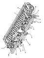
- the figure shows a harrow 2 as a harrow 1, which has a frame 3, on which the tool gyroscope 4 with their drive shafts 6 with the tines 5 are arranged next to one another and behind one another.
- the electric motors 7 with integrated transmission 8 are located above the tool gyro 4.
- the supports 9 are used for fastening the electric motors 7 and gear 8 to the frame 3.
- the individual tool gyros 4 are, as already mentioned above, juxtaposed and arranged one behind the other.
- the front implement rotors are connected via short beams 11 to the frame 3, the rear tool rotors via the longer carrier 10.
- the harrow 2 can be connected via the three-point tower 12 with the three-point linkage of a tractor.
- the harrow 2 is also a height-adjustable follower roller 15 downstream, which additionally processed and reconsolidated the machined and loosened soil.
Landscapes
- Life Sciences & Earth Sciences (AREA)
- Engineering & Computer Science (AREA)
- Mechanical Engineering (AREA)
- Soil Sciences (AREA)
- Environmental Sciences (AREA)
- Power Engineering (AREA)
- Soil Working Implements (AREA)
- Agricultural Machines (AREA)
Description
- Die Erfindung betrifft ein Bodenbearbeitungsgerät gemäß dem Oberbegriff des Patentanspruches 1.
- Aus der
FR 2 183 571 DE-PS 834 045 WO 92/01363 DE 100 10 819 A1 zu entnehmen. Der Gegenstand dieser Patentanmeldung ist ein Traktor mit eigener Bordelektronik, Bordcomputer und Stromsteckdose, bei dem die an der Stromsteckdose anstehende Spannung so geregelt werden kann, dass bei einer Kreiselegge mit einem Elektromotor für den Antrieb der Werkzeugkreisel die Drehzahl der Werkzeugkreisel den Gegebenheiten angepasst werden kann. Diese Patentanmeldung lehrt, dass für eine Kreiselegge bzw. für eine klappbare Kreiselegge kein aufwendiger Antriebsstrang mit Gelenkwellen benötigt wird. Vielmehr können die bei klappbaren Kreiseleggen üblichen Kreiseleggenhälften jeweils über einen Elektromotor angetrieben werden. Bei einer Kreiselegge, die mit dem vorgeschlagenen Traktor eingesetzt werden kann, wird nur ein Werkzeugkreisel vom Elektromotor angetrieben und das Antriebsmoment über Zahnräder auch auf die jeweils benachbarten Zahnräder und Werkzeugkreisel übertragen. Nachteilig ist hier, dass die Zahnräder sehr stabil ausgelegt werden müssen, da sie das Antriebsmoment für mehrere Werkzeugkreisel übertragen müssen. Bei einer 4 m breiten Kreiselegge muss das erste Zahnrad im Antriebsstrang fast die 9-fache Stabilität aufweisen wie eigentlich erforderlich. - Aufgabe der Erfindung ist es, eine Kreiselegge zu schaffen, bei der keine Überdimensionierung von Bauteilen wie Zahnräder und Zinken erforderlich wird, bei der der Arbeitseffekt individuell einstellbar ist, bei der der Leistungsbedarf äußert gering ist.
- Die Aufgabe der Erfindung wird durch die Merkmale des kennzeichnenden Teils des Patentanspruches 1 gelöst.
- Dadurch dass jeder Werkzeugkreisel über einen separaten Elektromotor angetrieben wird, kann neben dem üblichen Antriebsstrang auch auf die üblichen Zahnräder verzichtet werden, über die der Antrieb von Werkzeugkreisel zu Werkzeugkreisel erfolgt. Jeder Werkzeugkreisel mit Elektromotor braucht nur für die individuellen Belastungen ausgelegt zu sein. Auf zusätzliche Antriebselemente kann verzichtet werden.
- Erfindungsgemäß ist weiter vorgesehen, dass der Abstand der benachbarten Antriebswellen zueinander größer ist als der Durchmesser der Umlaufbahn der Zinken der drehbaren Werkzeugkreisel. Durch diese Maßnahme wird sichergestellt, dass jeder Werkzeugkreisel mit seinen Zinken unabhängig vom benachbarten Werkzeugkreisel mit Zinken arbeiten kann. Die Drehgeschwindigkeit braucht nicht synchron zu sein, die einzelnen Werkzeugkreisel können mit unterschiedlichen Drehzahlen betrieben werden.
- Mit Blick auf den Antrieb ist daran gedacht, dass die Stromversorgung der Elektromotoren über einen Generator erfolgt, der vorzugsweise dem Traktor oder dem Bodenbearbeitungsgerät zugeordnet ist. Der Generator kann so direkt vom Traktormotor angetrieben werden, aber auch Bestandteil eines Bodenbearbeitungsgerätes mit einer Gelenkwelle sein, die die Antriebsleistung des Traktormotors auf den Generator überträgt.
- Zusätzlich wird vorgeschlagen, dass zwischen dem Generator und den Elektromotoren mindestens ein Antriebsregler zwischengeschaltet ist und dass über eine Steuerung die Motordrehzahl so geregelt wird, dass die Drehzahl der Werkzeugkreisel den eingestellten, programmierten oder den über ein digitales Bestimmungssystem der Position, z.B. ein GPS Empfänger, empfangenen Vorgaben entspricht. Abhängig von diesen Vorgaben wird so die Drehzahl der Werkzeugkreisel erhöht oder reduziert, so wie es die vorliegenden Gegebenheiten erfordern. Diese Vorgaben können von einer Flächendatei stammen, sie können auch einprogrammiert sein oder einfach manuell umgesetzt werden.
- Es ist außerdem eine Vorrichtung vorgesehen, die die Struktur des bearbeiteten Bodens erfasst und dass über die Steuerung die Drehzahl und auch die Drehrichtung der Werkzeugkreisel so eingestellt werden, dass die gewünschte Struktur des Bodens erreicht wird. Über Kamerasysteme mit entsprechenden Auswertungsprogrammen oder Sensoren, kann so ermittelt werden, ob der Boden zu intensiv oder unzureichend bearbeitet wird. Die Drehzahl der Werkzeugkreisel mit den Zinken kann dann so verändert werden, dass die gewünschte Krümelstruktur erzielt wird. Werden dabei zum Beispiel Zinken eingesetzt, die auf Griff gestellt sind oder schleppend angeordnet sind, kann auch die Umkehr der Drehrichtung der Werkzeugkreisel dazu benutzt werden, die gewünschte Bodenstruktur zu erreichen.
- Was den Motor betrifft, ist vorgesehen, dass der jeweilige Elektromotor als Servomotor, Synchronmotor oder Asynchronmotor ausgebildet ist, der hinsichtlich der Drehrichtung reversierbar ist und mit einer Spannung zwischen 380 Volt und 750 Volt versorgt wird. Um einen möglichst effizienten Wirkungsgrad zu erreichen, empfiehlt sich eine Spannung zwischen 380 Volt und 750 Volt, wobei auch höhere Spannungen denkbar sind. Sinnvoll ist es allerdings, den zuvor genannten Spannungsbereich zu nutzen, da diese Technik bereits bei stationären Maschinen gut bewährt eingesetzt wird.
- Die Erfindung sieht weiter vor, dass der jeweilige Elektromotor mit einem Freilauf und/oder einer Reversiereinrichtung ausgestattet ist, die bei Erreichen eines vorgegebenen Grenzantriebsmomentes oder einer entsprechend hohen Stromaufnahme des zugehörigen Elektromotors aktivierbar ausgebildet sind. Sollten die Zinken eines Werkzeugkreisels auf ein Hindernis stoßen, kann so zum Schutz vor Beschädigungen des Gerätes, des Werkzeugkreisels oder des Elektromotors der Antrieb abgeschaltet werden. Umgekehrt kann so z.B. auch durch kurzzeitige Drehrichtungsumkehr ein bereits zwischen den Zinken des benachbarten Kreisels eingeklemmter Stein wieder frei gegeben werden.
- Weiterhin ist zwischen dem jeweiligen Elektromotor und der Antriebswelle ein Getriebe vorgesehen, das eine Untersetzung oder Übersetzung der Drehzahl des Werkzeugkreisels im Verhältnis zur Drehzahl des Elektromotors bewirkend ausgebildet ist. Zum einen können so Elektromotoren eingesetzt werden, die z.B. mit einer hohen Drehzahl arbeiten und dementsprechend leicht ausgebildet sein können, zum anderen kann die Drehzahl der Werkzeugkreisel auch gering gehalten werden, was zu Energieeinsparungen führt, wenn die Bodenverhältnisse eine derartige geringe Drehzahl der Werkzeugkreisel zulassen.
- Nach einer weiteren vorteilhaften Ausführungsform der Erfindung sind mindestens zwei Werkzeugkreisel mit Elektromotor verschiebbar, versetzbar oder verschwenkbar am Rahmen angeordnet. Diese Ausführungsform gewährleistet, dass der Boden jeweils optimal bearbeitet werden kann. Üblicherweise hinterlässt der Traktor Fahrspuren, die eine intensivere oder zumindest eine andere Bearbeitung des befahrenen Bodens erfordern. Je nach vorhandener Fahrspur können so einzelne Werkzeugkreisel in eine Position gebracht werden, die für eine optimale Lockerung bzw. Egalisierung der Fahrspur ackerbaulich am günstigsten ist. Seitlich verschwenkbare Werkzeugkreisel können so zum Beispiel über Federelemente in Position gehalten werden und bei Auftreffen auf ein Hindernis zusätzlich seitlich ausweichen.
- Die Erfindung sieht weiter vor, dass mindestens zwei Werkzeugkreisel über Lenker vertikal schwenkbar und vorzugsweise parallel geführt am Rahmen angeordnet und in der Arbeitstiefe einstellbar ausgebildet sind. Diese Ausbildungsform ermöglicht es, dass die einzelnen Werkzeugkreisel unterschiedlich tief arbeiten können, so wie es für die vorliegenden Bodenverhältnisse optimal ist. Umgekehrt können so auch Werkzeugkreisel hoch geschwenkt und still gesetzt werden bzw. auch nach oben ausweichen, wenn die Zinken eines Werkzeugkreisets gegen ein Bodenhindernis stoßen. Umgekehrt kann auch bei der letzten Überfahrt auf dem Feld, wenn zum Beispiel nur noch ein schmaler Streifen bearbeitet werden muss, verhindert werden, dass benachbartes Land bearbeitet wird, bzw. Bodenstellen doppelt bearbeitet werden. Dadurch wird übermäßiger Zinkenverschleiß verhindert, Teilbreiten der Kreiselegge können so auch bei Bedarf abgeschaltet werden, wie es z.B. bereits bei Drillmaschinen oder Feldspritzen bekannt ist.
- Es empfiehlt sich darüber hinaus, dass die Werkzeugkreisel den Anforderungen entsprechend in unterschiedlichen Abständen zueinander und in unterschiedlichen Winkellagen zum Boden angeordnet sind. Diese Maßnahme ermöglicht es, je nach Bedarf, die Arbeitsintensität in Teilbereichen des Gerätes zu erhöhen bzw. durch Schrägstellung der Werkzeugkreisel, den Boden gezielt zu bewegen, z.B. in eine noch nicht absolut eingeebnete Spurrille des Traktors.
- Weitere Einzelheiten und Vorteile des Erfindungsgegenstandes ergeben sich aus der nachfolgenden Beschreibung und der zugehörigen Zeichnung. Dargestellt ist eine Kreiselegge mit separat angetriebenen Werkzeugkreiseln.
- Die Figur zeigt eine Kreiselegge 2 als Bodenbearbeitungsgerät 1, die einen Rahmen 3 aufweist, an dem die Werkzeugkreisel 4 mit ihren Antriebswellen 6 mit den Zinken 5 nebeneinander und hintereinander versetzt angeordnet sind. Oberhalb der Werkzeugkreisel 4 befinden sich die Elektromotoren 7 mit integriertem Getriebe 8. Für die Befestigung der Elektromotoren 7 und Getriebe 8 mit dem Rahmen 3 dienen die Träger 9. Die einzelnen Werkzeugkreisel 4 sind, wie bereits zuvor erwähnt, nebeneinander und hintereinander versetzt angeordnet. Die vorderen Werkzeugkreisel sind über kurze Träger 11 mit dem Rahmen 3 verbunden, die hinteren Werkzeugkreisel über die längeren Träger 10. Die Kreiselegge 2 kann über den Dreipunktturm 12 mit dem Dreipunktgestänge eines Traktors verbunden werden. Dazu dient der obere Anlenkpunkt 13 und die unteren Anlenkpunkte 14. Der Kreiselegge 2 ist auch eine höheneinstellbare Nachlaufwalze 15 nachgeordnet, die den bearbeiteten und gelockerten Boden zusätzlich bearbeitet und rückverfestigt.
Claims (10)
- Kreiselegge (2) mit einem Rahmen (3) und nebeneinander angeordneten drehbaren Werkzeugkreiseln (4) mit Zinken (5), die über Antriebswellen (6) mit dem Rahmen (3) verbunden sind, wobei die drehbaren Werkzeugkreisel (4) über einen Elektromotor angetrieben sind und
jeder Werkzeugkreisel (4) über einen separaten Elektromotor (7) angetrieben wird, wobei der jeweilige Elektromotor (7) oberhalb der Werkzeugkreisel (4) angeordnet ist,
dadurch gekennzeichnet,
dass eine Vorrichtung vorgesehen ist, die die Struktur des bearbeiteten Bodens erfasst und dass über die Steuerung die Drehzahl und auch die Drehrichtung der Werkzeugkreisel so eingestellt werden, dass die gewünschte Struktur des Bodens erreicht wird. - Kreiselegge nach Anspruch 1,
dadurch gekennzeichnet,
dass der Abstand der benachbarten Antriebswellen (6) zueinander größer ist als der Durchmesser der Umlaufbahn der Zinken (5) der drehbaren Werkzeugkreisel (4). - Kreiselegge nach Anspruch 1,
dadurch gekennzeichnet,
dass die Stromversorgung der Elektromotoren (7) über einen Generator erfolgt, der vorzugsweise dem Traktor oder der Kreiselegge (2) zugeordnet ist. - Kreiselegge nach Anspruch 3,
dadurch gekennzeichnet,
dass zwischen dem Generator und den Elektromotoren (7) mindestens ein Antriebsregler zwischengeschaltet ist und dass über eine Steuerung die Motordrehzahl so geregelt wird, dass die Drehzahl der Werkzeugkreisel (4) den eingestellten, programmierten oder den über ein digitales Bestimmungssystem der Position, z.B. ein GPS Empfänger, empfangenen Vorgaben entspricht. - Kreiselegge nach Anspruch 1,
dadurch gekennzeichnet,
dass der jeweilige Elektromotor (7) als Servomotor, Synchronmotor oder Asynchronmotor ausgebildet ist, der hinsichtlich der Drehrichtung reversierbar ist und mit einer Spannung zwischen 380 Volt und 750 Volt versorgt wird. - Kreiselegge nach Anspruch 1,
dadurch gekennzeichnet,
dass der jeweilige Elektromotor (7) mit einem Freilauf und/oder einer Reversiereinrichtung ausgestattet ist, die bei Erreichen eines vorgegebenen Grenzantriebsmomentes oder einer entsprechend hohen Stromaufnahme des zugehörigen Elektromotors (7) aktivierbar ausgebildet sind. - Kreiselegge nach Anspruch 1,
dadurch gekennzeichnet,
dass zwischen dem jeweiligen Elektromotor (7) und der Antriebswelle (6) ein Getriebe (8) vorgesehen ist, das eine Untersetzung oder Übersetzung der Drehzahl des Werkzeugkreisels (4) im Verhältnis zur Drehzahl des Elektromotors (7) bewirkend ausgebildet ist. - Kreiselegge nach Anspruch 1,
dadurch gekennzeichnet,
dass mindestens zwei Werkzeugkreisel (4) mit Elektromotor (7) verschiebbar, versetzbar oder verschwenkbar am Rahmen (3) angeordnet sind. - Kreiselegge nach Anspruch 1,
dadurch gekennzeichnet,
dass mindestens zwei Werkzeugkreisel (4) über Lenker vertikal schwenkbar und vorzugsweise parallel geführt am Rahmen (3) angeordnet und in der Arbeitstiefe einstellbar ausgebildet sind. - Kreiselegge nach Anspruch 1,
dadurch gekennzeichnet,
dass die Werkzeugkreisel (4) den Anforderungen entsprechend in unterschiedlichen Abständen zueinander und in unterschiedlichen Winkellagen zum Boden angeordnet sind.
Priority Applications (1)
| Application Number | Priority Date | Filing Date | Title |
|---|---|---|---|
| PL11002603T PL2371190T3 (pl) | 2010-03-30 | 2011-03-30 | Przyrząd do uprawy roli, w szczególności brona karuzelowa z oddzielnymi silnikami elektrycznymi |
Applications Claiming Priority (1)
| Application Number | Priority Date | Filing Date | Title |
|---|---|---|---|
| DE102010013407A DE102010013407A1 (de) | 2010-03-30 | 2010-03-30 | Bodenbearbeitungsgerät, insbesondere Kreiselegge |
Publications (2)
| Publication Number | Publication Date |
|---|---|
| EP2371190A1 EP2371190A1 (de) | 2011-10-05 |
| EP2371190B1 true EP2371190B1 (de) | 2015-07-01 |
Family
ID=44168447
Family Applications (1)
| Application Number | Title | Priority Date | Filing Date |
|---|---|---|---|
| EP11002603.6A Active EP2371190B1 (de) | 2010-03-30 | 2011-03-30 | Bodenbearbeitungsgerät, insbesondere Kreiselegge mit separaten Elektromotoren |
Country Status (5)
| Country | Link |
|---|---|
| EP (1) | EP2371190B1 (de) |
| DE (1) | DE102010013407A1 (de) |
| DK (1) | DK2371190T3 (de) |
| ES (1) | ES2547565T3 (de) |
| PL (1) | PL2371190T3 (de) |
Cited By (1)
| Publication number | Priority date | Publication date | Assignee | Title |
|---|---|---|---|---|
| US20200359542A1 (en) * | 2019-05-16 | 2020-11-19 | Technische Universität Dresden | Method for agricultural soil cultivation, tool system, generator module, and their use |
Families Citing this family (3)
| Publication number | Priority date | Publication date | Assignee | Title |
|---|---|---|---|---|
| WO2018020310A1 (en) | 2016-07-25 | 2018-02-01 | Agco Corporation | Disc harrow with gang plugging detection |
| IT201700025808A1 (it) * | 2017-03-08 | 2018-09-08 | Flavio Ferranti | Veicolo agricolo |
| SE2351054A1 (en) * | 2023-09-08 | 2025-03-09 | Vaederstad Holding Ab | Agricultural implements comprising a straw harrow |
Citations (1)
| Publication number | Priority date | Publication date | Assignee | Title |
|---|---|---|---|---|
| DE2805932A1 (de) * | 1977-02-16 | 1978-08-17 | Downing Jun | Gesamtelektrischer, modularer traktor, insbesondere fuer die landwirtschaft |
Family Cites Families (5)
| Publication number | Priority date | Publication date | Assignee | Title |
|---|---|---|---|---|
| DE834045C (de) * | 1950-08-02 | 1952-03-13 | Otto Wedel | Dieselelektrische Zugmaschine mit Anbau-, Anhaengegeraeten und Anhaengern |
| FR2183571B1 (de) * | 1972-05-10 | 1974-08-30 | Santerre Atel Const Meta | |
| FR2664788B1 (fr) * | 1990-07-17 | 1994-07-08 | Ecolasse Guy | Sarcleuse rotative a reglage automatique pour nettoyage par des rotors de l'espace entre les cultures en sillon. |
| DE10010819A1 (de) | 2000-03-08 | 2001-09-13 | Lemken Gmbh & Co Kg | Traktor mit Stromsteckdose |
| DE102007053577A1 (de) * | 2007-11-09 | 2009-05-20 | Alois Pöttinger Maschinenfabrik Gmbh | Landmaschine |
-
2010
- 2010-03-30 DE DE102010013407A patent/DE102010013407A1/de not_active Withdrawn
-
2011
- 2011-03-30 EP EP11002603.6A patent/EP2371190B1/de active Active
- 2011-03-30 DK DK11002603.6T patent/DK2371190T3/en active
- 2011-03-30 PL PL11002603T patent/PL2371190T3/pl unknown
- 2011-03-30 ES ES11002603.6T patent/ES2547565T3/es active Active
Patent Citations (1)
| Publication number | Priority date | Publication date | Assignee | Title |
|---|---|---|---|---|
| DE2805932A1 (de) * | 1977-02-16 | 1978-08-17 | Downing Jun | Gesamtelektrischer, modularer traktor, insbesondere fuer die landwirtschaft |
Cited By (2)
| Publication number | Priority date | Publication date | Assignee | Title |
|---|---|---|---|---|
| US20200359542A1 (en) * | 2019-05-16 | 2020-11-19 | Technische Universität Dresden | Method for agricultural soil cultivation, tool system, generator module, and their use |
| EP3750386B1 (de) * | 2019-05-16 | 2022-11-02 | Kronos GmbH | Verfahren zur landwirtschaftlichen bodenbearbeitung, werkzeugsystem, generatormodul sowie deren verwendung |
Also Published As
| Publication number | Publication date |
|---|---|
| DE102010013407A1 (de) | 2011-10-06 |
| EP2371190A1 (de) | 2011-10-05 |
| PL2371190T3 (pl) | 2016-01-29 |
| ES2547565T3 (es) | 2015-10-07 |
| DK2371190T3 (en) | 2015-09-28 |
Similar Documents
| Publication | Publication Date | Title |
|---|---|---|
| DE3877766T2 (de) | Anordnung zum einstellen von gegenstaenden in der umgebung eines fahrers. | |
| DE891633C (de) | Motorisch betriebenes Bodenbearbeitungsgeraet mit umlaufenden Werkzeugen | |
| EP2371190B1 (de) | Bodenbearbeitungsgerät, insbesondere Kreiselegge mit separaten Elektromotoren | |
| EP1925196A2 (de) | Sämaschine | |
| EP3918898B1 (de) | Landwirtschaftliche maschine | |
| EP1505862B1 (de) | Bodenbearbeitungsgerät | |
| EP3025569B1 (de) | Mulcher | |
| DE102014014131A1 (de) | Heuwerbungsmaschine | |
| EP2371191B1 (de) | An einen Traktor angebautes oder angehängtes Bodenbearbeitungsgerät | |
| DE2639272A1 (de) | Bodenbearbeitungsmaschine | |
| DE3008216A1 (de) | Landwirtschaftliche mehrfachmaschine fuer die bodenbearbeitung in reihen | |
| DE3436123A1 (de) | Bodenbearbeitungsmaschine, insbesondere kreiselegge | |
| EP1295520A2 (de) | Kreiselegge mit verbessertem Rotorantrieb | |
| EP3011811A1 (de) | Pflug | |
| DE375408C (de) | Bodenbearbeitungsmaschine mit um eine senkrechte oder schraege Achse kreisenden Werkzeugen | |
| EP0916242A2 (de) | Bodenbearbeitungsmaschine | |
| EP0140318A1 (de) | Höhenstellvorrichtung für ein Säorgan | |
| EP3079457B1 (de) | Antriebssystem | |
| DE3330745A1 (de) | Vorrichtung zur landwirtschaftlichen bodenbearbeitung | |
| DE3222503A1 (de) | Stockraeumgeraet | |
| DE202015004426U1 (de) | Reinigungsgerät zur Reinigung von Boden- und Kantenflächen | |
| DE830123C (de) | Motoreggenaggregat mit von der Zapfwelle eines Schleppers angetriebenen Stachelwalzen | |
| DE19719208C2 (de) | Antriebseinrichtung für Pflüge, insbesondere Drehpflüge | |
| EP2929768B1 (de) | Landwirtschaftliches gerät zur bodenbearbeitung und maschinenkombination | |
| DE2617970A1 (de) | Heuwerbungsmaschine |
Legal Events
| Date | Code | Title | Description |
|---|---|---|---|
| PUAI | Public reference made under article 153(3) epc to a published international application that has entered the european phase |
Free format text: ORIGINAL CODE: 0009012 |
|
| AK | Designated contracting states |
Kind code of ref document: A1 Designated state(s): AL AT BE BG CH CY CZ DE DK EE ES FI FR GB GR HR HU IE IS IT LI LT LU LV MC MK MT NL NO PL PT RO RS SE SI SK SM TR |
|
| AX | Request for extension of the european patent |
Extension state: BA ME |
|
| 17P | Request for examination filed |
Effective date: 20120405 |
|
| 17Q | First examination report despatched |
Effective date: 20120924 |
|
| GRAP | Despatch of communication of intention to grant a patent |
Free format text: ORIGINAL CODE: EPIDOSNIGR1 |
|
| RIC1 | Information provided on ipc code assigned before grant |
Ipc: A01B 33/08 20060101AFI20150213BHEP Ipc: A01B 49/02 20060101ALI20150213BHEP |
|
| INTG | Intention to grant announced |
Effective date: 20150325 |
|
| RIN1 | Information on inventor provided before grant (corrected) |
Inventor name: GERAATS, MARCEL Inventor name: BERENDSEN, MARK Inventor name: WERRIES, DIETER Inventor name: LUKAS, THOMAS Inventor name: PEASSENS, CHRISTIAN Inventor name: GEBBEKEN, MARTIN |
|
| GRAS | Grant fee paid |
Free format text: ORIGINAL CODE: EPIDOSNIGR3 |
|
| GRAA | (expected) grant |
Free format text: ORIGINAL CODE: 0009210 |
|
| RIN1 | Information on inventor provided before grant (corrected) |
Inventor name: WERRIES, DIETER Inventor name: BERENDSEN, MARK Inventor name: LUKAS, THOMAS Inventor name: GEBBEKEN, MARTIN Inventor name: GERAATS, MARCEL Inventor name: PAESSENS, CHRISTIAN |
|
| AK | Designated contracting states |
Kind code of ref document: B1 Designated state(s): AL AT BE BG CH CY CZ DE DK EE ES FI FR GB GR HR HU IE IS IT LI LT LU LV MC MK MT NL NO PL PT RO RS SE SI SK SM TR |
|
| REG | Reference to a national code |
Ref country code: GB Ref legal event code: FG4D Free format text: NOT ENGLISH |
|
| REG | Reference to a national code |
Ref country code: AT Ref legal event code: REF Ref document number: 733381 Country of ref document: AT Kind code of ref document: T Effective date: 20150715 Ref country code: CH Ref legal event code: EP |
|
| REG | Reference to a national code |
Ref country code: IE Ref legal event code: FG4D Free format text: LANGUAGE OF EP DOCUMENT: GERMAN |
|
| REG | Reference to a national code |
Ref country code: DE Ref legal event code: R096 Ref document number: 502011007170 Country of ref document: DE |
|
| RIN2 | Information on inventor provided after grant (corrected) |
Inventor name: WERRIES, DIETER Inventor name: BERENDSEN, MARK Inventor name: GERAATS, MARCEL Inventor name: LUKAS, THOMAS Inventor name: PAESSENS, CHRISTIAN Inventor name: GEBBEKEN, MARTIN |
|
| REG | Reference to a national code |
Ref country code: CH Ref legal event code: NV Representative=s name: WEINMANN ZIMMERLI, CH |
|
| REG | Reference to a national code |
Ref country code: DK Ref legal event code: T3 Effective date: 20150921 |
|
| REG | Reference to a national code |
Ref country code: ES Ref legal event code: FG2A Ref document number: 2547565 Country of ref document: ES Kind code of ref document: T3 Effective date: 20151007 |
|
| REG | Reference to a national code |
Ref country code: NL Ref legal event code: FP |
|
| REG | Reference to a national code |
Ref country code: LT Ref legal event code: MG4D |
|
| PG25 | Lapsed in a contracting state [announced via postgrant information from national office to epo] |
Ref country code: GR Free format text: LAPSE BECAUSE OF FAILURE TO SUBMIT A TRANSLATION OF THE DESCRIPTION OR TO PAY THE FEE WITHIN THE PRESCRIBED TIME-LIMIT Effective date: 20151002 Ref country code: LV Free format text: LAPSE BECAUSE OF FAILURE TO SUBMIT A TRANSLATION OF THE DESCRIPTION OR TO PAY THE FEE WITHIN THE PRESCRIBED TIME-LIMIT Effective date: 20150701 Ref country code: FI Free format text: LAPSE BECAUSE OF FAILURE TO SUBMIT A TRANSLATION OF THE DESCRIPTION OR TO PAY THE FEE WITHIN THE PRESCRIBED TIME-LIMIT Effective date: 20150701 Ref country code: LT Free format text: LAPSE BECAUSE OF FAILURE TO SUBMIT A TRANSLATION OF THE DESCRIPTION OR TO PAY THE FEE WITHIN THE PRESCRIBED TIME-LIMIT Effective date: 20150701 Ref country code: NO Free format text: LAPSE BECAUSE OF FAILURE TO SUBMIT A TRANSLATION OF THE DESCRIPTION OR TO PAY THE FEE WITHIN THE PRESCRIBED TIME-LIMIT Effective date: 20151001 |
|
| PG25 | Lapsed in a contracting state [announced via postgrant information from national office to epo] |
Ref country code: HR Free format text: LAPSE BECAUSE OF FAILURE TO SUBMIT A TRANSLATION OF THE DESCRIPTION OR TO PAY THE FEE WITHIN THE PRESCRIBED TIME-LIMIT Effective date: 20150701 Ref country code: RS Free format text: LAPSE BECAUSE OF FAILURE TO SUBMIT A TRANSLATION OF THE DESCRIPTION OR TO PAY THE FEE WITHIN THE PRESCRIBED TIME-LIMIT Effective date: 20150701 Ref country code: IS Free format text: LAPSE BECAUSE OF FAILURE TO SUBMIT A TRANSLATION OF THE DESCRIPTION OR TO PAY THE FEE WITHIN THE PRESCRIBED TIME-LIMIT Effective date: 20151101 Ref country code: SE Free format text: LAPSE BECAUSE OF FAILURE TO SUBMIT A TRANSLATION OF THE DESCRIPTION OR TO PAY THE FEE WITHIN THE PRESCRIBED TIME-LIMIT Effective date: 20150701 Ref country code: PT Free format text: LAPSE BECAUSE OF FAILURE TO SUBMIT A TRANSLATION OF THE DESCRIPTION OR TO PAY THE FEE WITHIN THE PRESCRIBED TIME-LIMIT Effective date: 20151102 |
|
| REG | Reference to a national code |
Ref country code: FR Ref legal event code: PLFP Year of fee payment: 6 |
|
| REG | Reference to a national code |
Ref country code: DE Ref legal event code: R097 Ref document number: 502011007170 Country of ref document: DE |
|
| PG25 | Lapsed in a contracting state [announced via postgrant information from national office to epo] |
Ref country code: SK Free format text: LAPSE BECAUSE OF FAILURE TO SUBMIT A TRANSLATION OF THE DESCRIPTION OR TO PAY THE FEE WITHIN THE PRESCRIBED TIME-LIMIT Effective date: 20150701 Ref country code: EE Free format text: LAPSE BECAUSE OF FAILURE TO SUBMIT A TRANSLATION OF THE DESCRIPTION OR TO PAY THE FEE WITHIN THE PRESCRIBED TIME-LIMIT Effective date: 20150701 |
|
| PLBE | No opposition filed within time limit |
Free format text: ORIGINAL CODE: 0009261 |
|
| STAA | Information on the status of an ep patent application or granted ep patent |
Free format text: STATUS: NO OPPOSITION FILED WITHIN TIME LIMIT |
|
| PG25 | Lapsed in a contracting state [announced via postgrant information from national office to epo] |
Ref country code: RO Free format text: LAPSE BECAUSE OF FAILURE TO SUBMIT A TRANSLATION OF THE DESCRIPTION OR TO PAY THE FEE WITHIN THE PRESCRIBED TIME-LIMIT Effective date: 20150701 |
|
| 26N | No opposition filed |
Effective date: 20160404 |
|
| PG25 | Lapsed in a contracting state [announced via postgrant information from national office to epo] |
Ref country code: SI Free format text: LAPSE BECAUSE OF FAILURE TO SUBMIT A TRANSLATION OF THE DESCRIPTION OR TO PAY THE FEE WITHIN THE PRESCRIBED TIME-LIMIT Effective date: 20150701 |
|
| PG25 | Lapsed in a contracting state [announced via postgrant information from national office to epo] |
Ref country code: MC Free format text: LAPSE BECAUSE OF FAILURE TO SUBMIT A TRANSLATION OF THE DESCRIPTION OR TO PAY THE FEE WITHIN THE PRESCRIBED TIME-LIMIT Effective date: 20150701 Ref country code: LU Free format text: LAPSE BECAUSE OF FAILURE TO SUBMIT A TRANSLATION OF THE DESCRIPTION OR TO PAY THE FEE WITHIN THE PRESCRIBED TIME-LIMIT Effective date: 20160330 |
|
| REG | Reference to a national code |
Ref country code: FR Ref legal event code: PLFP Year of fee payment: 7 |
|
| PG25 | Lapsed in a contracting state [announced via postgrant information from national office to epo] |
Ref country code: IT Free format text: LAPSE BECAUSE OF NON-PAYMENT OF DUE FEES Effective date: 20160330 |
|
| PG25 | Lapsed in a contracting state [announced via postgrant information from national office to epo] |
Ref country code: MT Free format text: LAPSE BECAUSE OF FAILURE TO SUBMIT A TRANSLATION OF THE DESCRIPTION OR TO PAY THE FEE WITHIN THE PRESCRIBED TIME-LIMIT Effective date: 20150701 Ref country code: IT Free format text: LAPSE BECAUSE OF NON-PAYMENT OF DUE FEES Effective date: 20160330 |
|
| PGRI | Patent reinstated in contracting state [announced from national office to epo] |
Ref country code: IT Effective date: 20170710 |
|
| REG | Reference to a national code |
Ref country code: FR Ref legal event code: PLFP Year of fee payment: 8 |
|
| PG25 | Lapsed in a contracting state [announced via postgrant information from national office to epo] |
Ref country code: HU Free format text: LAPSE BECAUSE OF FAILURE TO SUBMIT A TRANSLATION OF THE DESCRIPTION OR TO PAY THE FEE WITHIN THE PRESCRIBED TIME-LIMIT; INVALID AB INITIO Effective date: 20110330 Ref country code: CY Free format text: LAPSE BECAUSE OF FAILURE TO SUBMIT A TRANSLATION OF THE DESCRIPTION OR TO PAY THE FEE WITHIN THE PRESCRIBED TIME-LIMIT Effective date: 20150701 Ref country code: SM Free format text: LAPSE BECAUSE OF FAILURE TO SUBMIT A TRANSLATION OF THE DESCRIPTION OR TO PAY THE FEE WITHIN THE PRESCRIBED TIME-LIMIT Effective date: 20150701 |
|
| PG25 | Lapsed in a contracting state [announced via postgrant information from national office to epo] |
Ref country code: MK Free format text: LAPSE BECAUSE OF FAILURE TO SUBMIT A TRANSLATION OF THE DESCRIPTION OR TO PAY THE FEE WITHIN THE PRESCRIBED TIME-LIMIT Effective date: 20150701 Ref country code: TR Free format text: LAPSE BECAUSE OF FAILURE TO SUBMIT A TRANSLATION OF THE DESCRIPTION OR TO PAY THE FEE WITHIN THE PRESCRIBED TIME-LIMIT Effective date: 20150701 |
|
| PG25 | Lapsed in a contracting state [announced via postgrant information from national office to epo] |
Ref country code: BG Free format text: LAPSE BECAUSE OF FAILURE TO SUBMIT A TRANSLATION OF THE DESCRIPTION OR TO PAY THE FEE WITHIN THE PRESCRIBED TIME-LIMIT Effective date: 20150701 |
|
| PG25 | Lapsed in a contracting state [announced via postgrant information from national office to epo] |
Ref country code: AL Free format text: LAPSE BECAUSE OF FAILURE TO SUBMIT A TRANSLATION OF THE DESCRIPTION OR TO PAY THE FEE WITHIN THE PRESCRIBED TIME-LIMIT Effective date: 20150701 |
|
| PGFP | Annual fee paid to national office [announced via postgrant information from national office to epo] |
Ref country code: IE Payment date: 20190322 Year of fee payment: 9 |
|
| PGFP | Annual fee paid to national office [announced via postgrant information from national office to epo] |
Ref country code: NL Payment date: 20190325 Year of fee payment: 9 |
|
| PGFP | Annual fee paid to national office [announced via postgrant information from national office to epo] |
Ref country code: ES Payment date: 20190425 Year of fee payment: 9 |
|
| PGFP | Annual fee paid to national office [announced via postgrant information from national office to epo] |
Ref country code: BE Payment date: 20190328 Year of fee payment: 9 |
|
| REG | Reference to a national code |
Ref country code: CH Ref legal event code: PL |
|
| REG | Reference to a national code |
Ref country code: DK Ref legal event code: EBP Effective date: 20200331 |
|
| REG | Reference to a national code |
Ref country code: NL Ref legal event code: MM Effective date: 20200401 |
|
| REG | Reference to a national code |
Ref country code: BE Ref legal event code: MM Effective date: 20200331 |
|
| PG25 | Lapsed in a contracting state [announced via postgrant information from national office to epo] |
Ref country code: NL Free format text: LAPSE BECAUSE OF NON-PAYMENT OF DUE FEES Effective date: 20200401 |
|
| PG25 | Lapsed in a contracting state [announced via postgrant information from national office to epo] |
Ref country code: LI Free format text: LAPSE BECAUSE OF NON-PAYMENT OF DUE FEES Effective date: 20200331 Ref country code: CH Free format text: LAPSE BECAUSE OF NON-PAYMENT OF DUE FEES Effective date: 20200331 Ref country code: IE Free format text: LAPSE BECAUSE OF NON-PAYMENT OF DUE FEES Effective date: 20200330 |
|
| PG25 | Lapsed in a contracting state [announced via postgrant information from national office to epo] |
Ref country code: BE Free format text: LAPSE BECAUSE OF NON-PAYMENT OF DUE FEES Effective date: 20200331 |
|
| GBPC | Gb: european patent ceased through non-payment of renewal fee |
Effective date: 20200330 |
|
| PG25 | Lapsed in a contracting state [announced via postgrant information from national office to epo] |
Ref country code: GB Free format text: LAPSE BECAUSE OF NON-PAYMENT OF DUE FEES Effective date: 20200330 Ref country code: DK Free format text: LAPSE BECAUSE OF NON-PAYMENT OF DUE FEES Effective date: 20200331 |
|
| REG | Reference to a national code |
Ref country code: ES Ref legal event code: FD2A Effective date: 20210811 |
|
| PG25 | Lapsed in a contracting state [announced via postgrant information from national office to epo] |
Ref country code: ES Free format text: LAPSE BECAUSE OF NON-PAYMENT OF DUE FEES Effective date: 20200331 |
|
| PGFP | Annual fee paid to national office [announced via postgrant information from national office to epo] |
Ref country code: AT Payment date: 20230320 Year of fee payment: 13 |
|
| PGFP | Annual fee paid to national office [announced via postgrant information from national office to epo] |
Ref country code: PL Payment date: 20230317 Year of fee payment: 13 Ref country code: IT Payment date: 20230321 Year of fee payment: 13 |
|
| P01 | Opt-out of the competence of the unified patent court (upc) registered |
Effective date: 20230518 |
|
| PGFP | Annual fee paid to national office [announced via postgrant information from national office to epo] |
Ref country code: CZ Payment date: 20230330 Year of fee payment: 13 |
|
| REG | Reference to a national code |
Ref country code: DE Ref legal event code: R084 Ref document number: 502011007170 Country of ref document: DE |
|
| PG25 | Lapsed in a contracting state [announced via postgrant information from national office to epo] |
Ref country code: CZ Free format text: LAPSE BECAUSE OF NON-PAYMENT OF DUE FEES Effective date: 20240330 |
|
| PG25 | Lapsed in a contracting state [announced via postgrant information from national office to epo] |
Ref country code: CZ Free format text: LAPSE BECAUSE OF NON-PAYMENT OF DUE FEES Effective date: 20240330 |
|
| REG | Reference to a national code |
Ref country code: AT Ref legal event code: MM01 Ref document number: 733381 Country of ref document: AT Kind code of ref document: T Effective date: 20240330 |
|
| PG25 | Lapsed in a contracting state [announced via postgrant information from national office to epo] |
Ref country code: AT Free format text: LAPSE BECAUSE OF NON-PAYMENT OF DUE FEES Effective date: 20240330 |
|
| PG25 | Lapsed in a contracting state [announced via postgrant information from national office to epo] |
Ref country code: AT Free format text: LAPSE BECAUSE OF NON-PAYMENT OF DUE FEES Effective date: 20240330 |
|
| PGFP | Annual fee paid to national office [announced via postgrant information from national office to epo] |
Ref country code: DE Payment date: 20250307 Year of fee payment: 15 |
|
| PG25 | Lapsed in a contracting state [announced via postgrant information from national office to epo] |
Ref country code: PL Free format text: LAPSE BECAUSE OF NON-PAYMENT OF DUE FEES Effective date: 20240330 |
|
| PGFP | Annual fee paid to national office [announced via postgrant information from national office to epo] |
Ref country code: FR Payment date: 20250324 Year of fee payment: 15 |