EP2371067B1 - Switching voltage regulator with frequency selection - Google Patents
Switching voltage regulator with frequency selection Download PDFInfo
- Publication number
- EP2371067B1 EP2371067B1 EP09796513.1A EP09796513A EP2371067B1 EP 2371067 B1 EP2371067 B1 EP 2371067B1 EP 09796513 A EP09796513 A EP 09796513A EP 2371067 B1 EP2371067 B1 EP 2371067B1
- Authority
- EP
- European Patent Office
- Prior art keywords
- frequency
- switcher
- voltage regulator
- switching voltage
- fsw
- Prior art date
- Legal status (The legal status is an assumption and is not a legal conclusion. Google has not performed a legal analysis and makes no representation as to the accuracy of the status listed.)
- Active
Links
- 238000004891 communication Methods 0.000 claims description 25
- 238000000034 method Methods 0.000 claims description 17
- 238000001514 detection method Methods 0.000 claims description 9
- 238000000926 separation method Methods 0.000 claims description 7
- 230000001105 regulatory effect Effects 0.000 claims description 3
- 238000004590 computer program Methods 0.000 claims 1
- 238000010586 diagram Methods 0.000 description 21
- 238000012545 processing Methods 0.000 description 20
- 230000001413 cellular effect Effects 0.000 description 10
- 230000008569 process Effects 0.000 description 7
- 230000006870 function Effects 0.000 description 6
- 238000013461 design Methods 0.000 description 5
- 238000001914 filtration Methods 0.000 description 5
- 239000003990 capacitor Substances 0.000 description 4
- 230000000694 effects Effects 0.000 description 4
- 238000005516 engineering process Methods 0.000 description 4
- 238000006243 chemical reaction Methods 0.000 description 3
- 230000001419 dependent effect Effects 0.000 description 3
- 230000003595 spectral effect Effects 0.000 description 3
- 230000008878 coupling Effects 0.000 description 2
- 238000010168 coupling process Methods 0.000 description 2
- 238000005859 coupling reaction Methods 0.000 description 2
- 238000004146 energy storage Methods 0.000 description 2
- 230000000116 mitigating effect Effects 0.000 description 2
- 229910052710 silicon Inorganic materials 0.000 description 2
- 239000010703 silicon Substances 0.000 description 2
- 238000012360 testing method Methods 0.000 description 2
- 238000012546 transfer Methods 0.000 description 2
- 230000003321 amplification Effects 0.000 description 1
- 238000007796 conventional method Methods 0.000 description 1
- 239000013078 crystal Substances 0.000 description 1
- 238000002955 isolation Methods 0.000 description 1
- 229910001416 lithium ion Inorganic materials 0.000 description 1
- 238000005259 measurement Methods 0.000 description 1
- 238000012986 modification Methods 0.000 description 1
- 230000004048 modification Effects 0.000 description 1
- 238000012544 monitoring process Methods 0.000 description 1
- 238000003199 nucleic acid amplification method Methods 0.000 description 1
- 239000002245 particle Substances 0.000 description 1
- 239000000758 substrate Substances 0.000 description 1
- 230000007704 transition Effects 0.000 description 1
Images


Classifications
-
- H—ELECTRICITY
- H04—ELECTRIC COMMUNICATION TECHNIQUE
- H04B—TRANSMISSION
- H04B1/00—Details of transmission systems, not covered by a single one of groups H04B3/00 - H04B13/00; Details of transmission systems not characterised by the medium used for transmission
- H04B1/06—Receivers
- H04B1/10—Means associated with receiver for limiting or suppressing noise or interference
-
- G—PHYSICS
- G05—CONTROLLING; REGULATING
- G05F—SYSTEMS FOR REGULATING ELECTRIC OR MAGNETIC VARIABLES
- G05F1/00—Automatic systems in which deviations of an electric quantity from one or more predetermined values are detected at the output of the system and fed back to a device within the system to restore the detected quantity to its predetermined value or values, i.e. retroactive systems
- G05F1/10—Regulating voltage or current
-
- H—ELECTRICITY
- H02—GENERATION; CONVERSION OR DISTRIBUTION OF ELECTRIC POWER
- H02M—APPARATUS FOR CONVERSION BETWEEN AC AND AC, BETWEEN AC AND DC, OR BETWEEN DC AND DC, AND FOR USE WITH MAINS OR SIMILAR POWER SUPPLY SYSTEMS; CONVERSION OF DC OR AC INPUT POWER INTO SURGE OUTPUT POWER; CONTROL OR REGULATION THEREOF
- H02M1/00—Details of apparatus for conversion
- H02M1/44—Circuits or arrangements for compensating for electromagnetic interference in converters or inverters
-
- H—ELECTRICITY
- H02—GENERATION; CONVERSION OR DISTRIBUTION OF ELECTRIC POWER
- H02M—APPARATUS FOR CONVERSION BETWEEN AC AND AC, BETWEEN AC AND DC, OR BETWEEN DC AND DC, AND FOR USE WITH MAINS OR SIMILAR POWER SUPPLY SYSTEMS; CONVERSION OF DC OR AC INPUT POWER INTO SURGE OUTPUT POWER; CONTROL OR REGULATION THEREOF
- H02M3/00—Conversion of dc power input into dc power output
- H02M3/02—Conversion of dc power input into dc power output without intermediate conversion into ac
- H02M3/04—Conversion of dc power input into dc power output without intermediate conversion into ac by static converters
- H02M3/10—Conversion of dc power input into dc power output without intermediate conversion into ac by static converters using discharge tubes with control electrode or semiconductor devices with control electrode
- H02M3/145—Conversion of dc power input into dc power output without intermediate conversion into ac by static converters using discharge tubes with control electrode or semiconductor devices with control electrode using devices of a triode or transistor type requiring continuous application of a control signal
- H02M3/155—Conversion of dc power input into dc power output without intermediate conversion into ac by static converters using discharge tubes with control electrode or semiconductor devices with control electrode using devices of a triode or transistor type requiring continuous application of a control signal using semiconductor devices only
- H02M3/156—Conversion of dc power input into dc power output without intermediate conversion into ac by static converters using discharge tubes with control electrode or semiconductor devices with control electrode using devices of a triode or transistor type requiring continuous application of a control signal using semiconductor devices only with automatic control of output voltage or current, e.g. switching regulators
-
- H—ELECTRICITY
- H04—ELECTRIC COMMUNICATION TECHNIQUE
- H04B—TRANSMISSION
- H04B15/00—Suppression or limitation of noise or interference
Definitions
- the present disclosure relates generally to integrated circuits, and more specifically to switching voltage regulators in wireless communication devices.
- Wireless communication devices require a battery or external DC power supply for a power source.
- ICs integrated circuits
- These ICs typically operate at a much lower DC voltage than either a battery or an external DC power supply attached to the wireless communication device.
- a switching voltage regulator is usually required to convert either an external DC power supply or battery voltage to the integrated circuits lower supply voltage.
- a switching voltage regulator provides the highest power efficiency when the difference between the battery voltage (VBAT) and the integrated circuits supply voltage (VDD) is more than a couple hundred millivolts.
- the battery is composed of a Li-ion cell with a 3.6V nominal voltage and the integrated circuits operate at 1.8V. Therefore, the difference between the battery voltage and the integrated circuits voltage is 3.6 V - 1.8 V or 1.8 V.
- a switching voltage regulator is strongly preferred over a linear regulator.
- a linear regulator would experience the full 1.8V drop between the battery and the load. The power dissipated by a linear regulator is equal to 1.8V * IDD (the load current of the integrated circuits).
- a switching voltage regulator may dissipate only 10% of the energy used by the integrated circuit (over a wide range of load current), whereas a linear regulator would dissipate 100% of the energy used by the integrated circuit regardless of the load current. Switching voltage regulators are often used in wireless communication devices for this reason.
- Switching voltage regulators may convert between a higher input voltage and a lower output voltage using one or more electronic switches in conjunction with energy storage devices (inductors or capacitors) to transfer energy between a higher external DC power supply voltage and a lower integrated circuit voltage.
- a switching voltage regulator frequency is dictated by the output voltage ripple requirement, the size of the series inductor and load filtering capacitor within a switching voltage regulator, output DC load current, and desired power efficiency of a switching voltage regulator.
- RF radio frequency
- Each frequency component is a harmonic of the switcher frequency of the switching voltage regulator.
- a power level of each harmonic is dependent on (i) the duty cycle of the switcher frequency of the switching voltage regulator, (ii) the degree of capacitive filtering of the output voltage, as well as (iii) the type of coupling between the switching voltage regulator and the RF transceiver circuit.
- Radio frequency (RF) voltage-controlled oscillators are typically embedded in a RF transceiver and function as local oscillator(s) (LOs) to up-convert or down-convert communication signals from/to baseband to/from RF.
- LOs local oscillator
- voltage ripple at the output of the switching voltage regulator may combine with a frequency tuning element voltage of the RF VCO to create frequency modulation (FM) on the RF VCO output at offsets equal to the harmonics of the switching voltage regulator switcher frequency.
- FM frequency modulation
- the switching voltage regulator induced FM on the RF VCO causes harmonic spurious content to appear at offsets from the fundamental output carrier frequency of the RF VCO.
- This harmonic spurious content induced by the switching voltage regulator may interfere with the performance of a wireless communication device under certain operating conditions. For example, weak receive signal strength, the presence of external jammers at specific frequency offsets from a desired receive channel, and/or transmit leakage into a receive path in a full-duplex transceiver can all contribute to greater interference, in the presence of the
- Known ways to reduce the effect of switcher frequency spurious content caused by the switching voltage regulator in a wireless communication devices includes: (i) adjusting the frequency of the switching voltage regulator continuously using pulse width modulation, pulse density modulation, or frequency hopping; b) toggling between a switching voltage regulator and a linear regulator during receive only modes of the wireless communication transceiver; and (iii) moving the switching voltage regulator as far away (using shielding and differential signal paths for improved isolation) from sensitive VCO and other components, all of which introduce a level of design complexity or inefficient use of circuit board or integrated circuit area.
- WO02/19551 discloses a switched mode power supply including a modulator that provides a switching signal to control the switching of the switch of the supply.
- a square wave input at a frequency dependent upon the frequency band of a receive signal is provided to a ramp generator, from which a triangle or sawtooth wave is generated and provided to the inverting input of the modulator.
- the square wave input to the ramp generator may be obtained either through the use of multiple crystals of different resonance frequencies, or using a programmable frequency divider that is able to generate multiple frequencies by dividing down a base frequency.
- An error signal based on the difference between a reference voltage and the output voltage of the supply is provided to the non-inverting input of the modulator.
- the switcher frequency is set by adjusting a frequency setting input to a programmable clock divider.
- a processor drives a programmable clock divider which receives a value representative of a dividing factor by which to divide a reference clock frequency signal to generate a desired switcher frequency for the switching voltage regulator. Values of the programmable clock divider are selectively varied to achieve optimal performance and mitigate the effect of switcher frequency spurious content for a given operating condition or conditions.
- the device described therein may be used for various wireless communication frequency bands such as cellular, PCS, and IMT and air-interfaces such as CDMA, TDMA, FDMA, OFDMA, and SC-FDMA.
- this device may be used for local-area or personal-area network standards, WLAN, Bluetooth, & ultra-wideband (UWB).
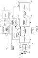
- FIG. 1 is a block diagram of a wireless communication device 10 in accordance with the present embodiment as shown.
- Wireless communication device 10 includes radio frequency (RF) antenna 12 connected to RF Front-End 14.
- RF Front-End 14 separates transmit and receive RF signal paths, and provides amplification and signal distribution.
- RF signals for transmit, TX_RF, and receive, RX_RF, are passed between transceiver 20 and RF Front-End 14.
- Transceiver 20 is configured to down-convert a RX_RF signal from RF to a signal for baseband I/Q demodulation by processor 70, which may be a baseband modem or the like. Transceiver 20 is similarly configured to up-convert a signal from processor 70, using baseband I/Q modulation, to a TX_RF signal. Signals to be up-converted and down-converted from/to baseband I/Q modulation are shown connected between transceiver 20 and processor 70.
- Memory 75 stores processor programs and data and may be implemented as a single integrated circuit (IC), as shown.
- IC integrated circuit
- Processor 70 is configured to demodulate incoming baseband receive I/Q signals, encode and modulates baseband transmit I/Q signals, and run applications from storage, such as memory 75, to process data or send data and commands to enable various circuit blocks, all in a known manner.
- processor 70 generates control signals to transceiver 20 through a data bus, serial bus, or a dedicated set of signals.
- control signals may include, for example, turning transceiver 20 on and off, measuring received signal strength, setting transmit RF signal power or receive signal path gains, changing RF channels, detecting receiver signal jammers, and switching transmit/receive signal blocks between high power and power saving modes.
- Processor 70 is also configured to read the state of transceiver 20, and at the same time also receive one or more interrupt signals (not shown) from transceiver 20. Interrupt signals are used to initiate commands and algorithms between transceiver 20 and processor 70.
- processor 70 the general operation of processor 70, transceiver 20, and memory 75 are well known and understood by those skilled in the art, and that various ways of implementing the associated functions are also well known, including providing or combining functions across fewer integrated circuits (ICs), or even within a single IC.
- ICs integrated circuits
- DC power is conventionally provided from a generic DC power source 60.
- DC power source 60 may consist of either an external DC power supply 61a (output voltage labeled VEXT) or a battery 61b (output voltage labeled VBAT). Either output voltage VEXT from DC power supply 61a or the output voltage VBAT from battery 61b drive a supply voltage into switching voltage regulator 40.
- Switching voltage regulator 40 is configured to convert supply voltage of VEXT or VBAT to individual supply voltages for powering each of processor 70 (BB_VDD), transceiver 20 (TCVR_VDD), memory 75 (MEM_VDD), and RF Front-End 14 (PA_VDD and VBIAS). Switching voltage regulator 40 may also provide supply voltages to other blocks as necessary (not shown).
- Switching voltage regulator 40 is configured to convert between a higher input voltage and a lower output voltage by toggling on and off, at a switcher frequency (hereafter "Fsw”), one or more switches in conjunction with energy storage devices (inductors or capacitors) to transfer energy between the higher input voltage and lower output voltage.
- Fsw switcher frequency
- processor 70 controls the switcher frequency, Fsw, of switching voltage regulator 40, depending on one or more conditions of transceiver 20. As previously described in the background of the disclosure, switching voltage regulator 40 may interfere with transceiver 20 operation.
- Transceiver 20 conditions include an operating mode (CDMA, TDMA, FDMA, OFDMA, SC-FDMA, GPS, ...) with associated receive signal bandwidth, operating frequency band (US cellular, US PCS, IMT, ...), and receive jamming detection circuit (jammer present, jammer power level, and jammer frequency offset from desired receive signal).
- Reference clock oscillator 80 generates a reference clock frequency signal, REF_CLK, as will be shown in subsequent FIGs. 2 , 3 , and 6 .
- RF Front-End 14, transceiver 20, switching voltage regulator 40, processor 70, memory 75, and reference clock oscillator 80 may reside on common silicon, separate silicon on a common package substrate, as separate packaged devices, or combinations thereof where appropriate from a functional or circuit design perspective.
- FIG. 2 is a block diagram of a radio frequency (RF) transceiver (transceiver 20) of FIG. 1 in accordance with the present embodiment as shown.
- Transceiver 20 includes transmit signal processing block 22, receive signal processing block 24, RF local oscillator (RF LO) generation block 28, and control and status block 26.
- Control and status block 26 provides digital control logic to/from processor 70 including a jammer detect signal.
- REF_CLK from reference clock oscillator 80, feeds into RF LO generation block 28.
- Transceiver 20 while shown with just one transmit and receive signal processing block, may also exist with any combination of multiple receive blocks, multiple transmit blocks, or any number of possible transmit and receive signal processing block configurations.
- transmit signal processor block 22 and receive signal processing block 24 are shown as separate functional blocks but may be combined to some extent in a half duplex radio device mode.
- RF LO generation block 28 while logically shown as a separate common block disposed between transmit signal processing block 22 and receive signal processing block 24, other configurations are contemplated.
- Control and status block 26 can be similarly reconfigured without departing from the scope of the preferred embodiments described herein.
- FIG. 3 is a diagram of a radio frequency (RF) local oscillator (LO) generation block 28 of FIG. 2 in accordance with the present embodiment as shown.
- RF LO generation block 28 includes a RX LO generation block 29 and a TX LO generation block 37.
- RX LO generation block 29 includes a channel selection tuning block 31 comprising a RF PLL and loop filter.
- Channel selection tuning block 31 compares REF_CLK from reference clock oscillator 80 to output signal, RX_VCO, from RF VCO 33 to lock RF VCO 33 to a desired frequency.
- the output, Vt, from channel selection tuning block 31 is an analog control signal for tuning the frequency of output signal RX_VCO of RF VCO 33.
- the output signal RX_VCO is further processed by LO generation block 35 and frequency converted to a desired receive RF channel frequency, RX_LO.
- LO generation block 35 may be implemented using frequency dividers, frequency mixers, switches, or a combination of all three types of elements to create a variety of frequency multiplication or division ratios between signals RX_VCO and RX_LO.
- the RX_LO signal frequency is equal to the desired RX RF channel frequency in a particular operating frequency band (US cellular, US-PCS, IMT, GPS, etc).
- RX_LO signal is connected to the receive signal processing block 24 of FIG. 2 .
- TX LO generation 37 An equivalent block for TX LO generation 37 is not shown for brevity. It should be readily understood that a similar block as shown for RX LO generation block 29 may be utilized for TX LO generation block 37 and as many LO generation blocks as required for multiple signal processing blocks of both RX and TX or RX only.
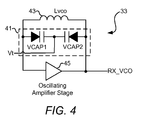
- FIG. 4 is a schematic diagram of the radio frequency voltage-controlled oscillator, RF VCO 33, of FIG. 3 in accordance with the present embodiment as shown.
- RF VCO 33 includes a fixed inductor Lvco 43 in parallel with two varactor elements 41 (VCAP1 and VCAP2) to shift the frequency of output signal RX_VCO. This frequency (in radians/sec) is equal to 1 Lvco * Cvcap , where Cvcap is the total capacitance of the two varactor elements 41 (VCAP1 and VCAP2).
- Frequency tuning is achieved by varying the total capacitance by adjusting the output, Vt, from channel selection tuning block 31 which is input across VCAP1 and VCAP2.
- the output of RF VCO 33, RX_VCO is then input back to channel selection tuning block 31 and into LO generation block 35, as shown in FIG. 3 .
- the circuit shown in FIG. 4 may apply across as many RF VCOs as required for multiple paths of both RX and TX.
- one RF VCO may cover multiple modes and operating bands as long as simultaneous operation in multiple frequency bands is not required.
- Other circuit topologies are known that can shift the output frequency of an RF VCO, but are functionally equivalent.
- FIG. 5 is a graphical illustration of RF VCO output frequency vs. tuning voltage (Vt) of FIG. 4 in accordance with the present embodiment as shown.
- Vt tuning voltage
- the frequency tuning range of RF VCO 33 is continuously adjusted by tuning voltage, Vt, between 0 and .7 volts DC.
- KV 5,000 MHz/V
- Kv 5000 MHz/V
- voltage ripple 1 uV
- Fsw 2 MHz
- the amplitude of the spurious content measured on the RF VCO 33 output will also increase in relative amplitude. As will be shown subsequently in FIGs. 7 and 8 , this spurious content may degrade transceiver 20 radio performance under different operating conditions.
- FIG. 6 is a schematic diagram of a switching voltage regulator 40 in accordance with a preferred embodiment of FIG. 1 .
- Switching voltage regulator 40 includes a voltage source input, VBAT, from power source 61b of FIG. 1 , and voltage output, TCVR_VDD for transceiver 20, PA_VDD and VBIAS for RF Front-End 14, BB_VDD for processor 70, and MEM_VDD for memory 75 of FIG. 1 .
- An alternate input voltage VEXT may also be used if selected by either switcher 40 or processor 70 in FIG. 1 .
- Individual output voltages such as PA_VDD, VBIAS, BB_VDD and MEM_VDD may be generated separately with additional switching voltage regulators if different supply voltages are required.
- VEXT and TCVR_VDD are switches 61a and 61b along with a switching voltage regulator controller 63, a programmable clock divider 64, a series inductor Lsw 65, and a shunt filtering capacitor Csw 67.
- Switching voltage regulator controller 63 compares the output voltage TCVR_VDD (along with PA_VDD, VBIAS, BB_VDD, and MEM_VDD) to a programmable voltage setting value based on a reference voltage generator 62 output voltage and adjusts the duty cycle of S1 and S2 such that the output voltage, TCVR_VDD (along with PA_VDD, VBIAS, BB_VDD, and MEM_VDD), converges to the programmed voltage setting value.
- the programmed voltage setting value is set by processor 70 or can be hardware configured to a fixed value internal to switching voltage regulator 40.
- the switcher frequency, Fsw to the switching voltage regulator controller 63, is set by a switcher frequency setting value for programmable clock divider 64.
- Programmable clock divider 64 may be an integer frequency divider between REF_CLK (from reference clock oscillator 80 in this example), and the switcher frequency, Fsw, used to control switches 61a and 61b.
- REF_CLK output frequency is 19.2 MHz and the programmable clock divider 64 is set between 3 different frequency setting values (divide by 6, 7, or 8) depending on the process shown subsequently in FIG. 9 .
- Switching voltage regulator 40 is coupled to transceiver 20 directly via the supply voltage TCVR_VDD as shown in FIGs. 1 and 6 .
- the switcher frequency, Fsw, of the switching voltage regulator 40 may interfere with the performance of transceiver 20.
- the interference appears as voltage ripple on TCVR_VDD.
- the voltage ripple is composed of discrete frequency components. Each frequency component is a harmonic of the switcher frequency, Fsw, of the switching voltage regulator 40.
- a power level of each harmonic is dependent on (i) the duty cycle of the switcher frequency, Fsw, of the switching voltage regulator 40, (ii) the degree of capacitive filtering of the output voltage TCVR_VDD, as well as (iii) the method of coupling between TCVR_VDD and sensitive circuits within transceiver 20.
- RF VCO 33 Voltage ripple at the output of the switching voltage regulator 40 may combine with the tuning voltage, Vt, of RF VCO 33 to create frequency modulation (FM) of the RF VCO 33 output, RX_VCO, at frequency offsets equal to the harmonics of the switcher frequency, Fsw, of switching voltage regulator 40.
- FM frequency modulation
- the switcher frequency, Fsw, of switching voltage regulator 40 may interfere with the performance of wireless communication device 10 under certain operating conditions.
- the first operating condition is based on a current operating technology mode (GSM, CDMA, WCDMA, etc).
- GSM current operating technology mode
- CDMA CDMA
- WCDMA WCDMA
- Fch RF channel bandwidth
- the switcher frequency, Fsw, of the switching voltage regulator 40, associated with a given technology mode is adjusted such that it is greater than half the RF channel bandwidth (Fsw>Fch/2).
- This switcher frequency adjustment reduces or eliminates switcher voltage regulator 40 interference on transceiver 20 from appearing on the baseband analog receive signals (RX_I_FILT and RX_Q_FILT in FIG. 2 ) and transmit signals (TX_I, TX_Q of FIG. 2 ).
- wireless communication device 10 operating in full duplex mode
- setting the switcher frequency of switching voltage regulator 40 higher than half the RF channel bandwidth is particularly useful in mitigating interference.
- the RF operating band includes only one frequency band of interest for that technology mode (US cellular, US PCS, CDMA in the IMT band, etc.).
- the operating frequency band is one of several possible frequency bands.
- D 45 MHz.
- D 80 MHz.
- the transmit RF channel (at Ftx) must not mix with spurious content (from switching voltage regulator 40), as it may create interference at the receive RF channel frequency (at Frx).
- the switcher frequency, Fsw, of switching voltage regulator 40 must, in fact, not fall within a range of frequencies such that D - Fch ⁇ N*Fsw ⁇ D + Fch where N*Fsw is the nearest integer switcher frequency harmonic to D.
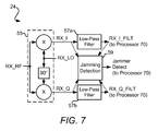
- FIG. 7 is a block diagram of receive signal processing block 24 in FIG. 2 in accordance with the present embodiment as shown.
- Receive signal processing block 24 includes RX RF I/Q down-converter 55, a pair of baseband analog low-pass filters 57a and 57b, and jamming detection block 59.
- Alternative embodiments may include low-noise amplifiers, RF filtering, multiple RF bands, and various forms of gain control circuitry.
- RX_RF signal from RF Front-End block 14 is fed into I/Q down-converter 55 as well as out-of-RX band interference prior to down-converting the receive RF signal using a direct-conversion (RF to baseband) I/Q mixers within I/Q down-converter 55.
- the outputs of I/Q down-converter 55, RX_I and RX_Q are filtered by low-pass filters 57a and 57b prior to further processing in either in analog (on either transceiver 20 or processor 70) or digital domain (after conversion with analog to digital converters on either transceiver 20 or processor 70).
- low-pass filters 57a and 57b may include fixed or variable gain to adjust RX_I_FILT and RX_Q_FILT amplitude prior to analog to digital conversion in processor 70.
- Jamming detection circuit 59 sends a jammer detect signal, which value communicates to processor 70 when jammers are present which are frequency offset from a selected receive channel.
- Jamming detection circuit 59 may take measurements in the baseband analog domain before or after analog low-pass filters 57a and/or 57b to detect the presence of jammers offset from the RX_I and RX_Q signals in frequency.
- jamming detection block 59 may be implemented in the digital domain in processor 70 or split between transceiver 20 and processor 70.
- This undesired mixing product may fall within the receive signal bandwidth measured at baseband receive signal path (RX_I, RX_Q, RX_I_FILT, and RX_Q_FILT of FIG. 7 ).
- the switcher frequency of the switching voltage regulator 40 is set so as to mitigate this interference in the baseband receive signal path when one or more jammers are present above a predefined and detectable threshold in the baseband receive signal path.
- the spurious content problem acting on receive signal processing block 24 as described above in connection with FIG. 2 and FIG. 7 may be graphically illustrated.
- FIG. 8 is a graphical illustration showing the impact of interference from a switching voltage regulator on (i) RF_LO output, (ii) transmit RF channel leakage, and (iii) receiver performance in the presence of jammers for FIGs. 1-7 in accordance with the present embodiment as shown.
- Illustration 90 includes an amplified/filtered RX_RF signal input with receive signal at Frx, transmit signal leakage at Ftx, and a jammer signal at Fj1 (from block 53 of FIG. 7 ) as input to I/Q down-converter 55 (of FIG. 7 ).
- Illustration 90 also includes a RX_LO signal (from block 35 of FIG.
- Illustration 90 also includes a RX_I signal from the in-phase, or I down-converter of I/Q down-converter 55 of FIG. 7 .
- the illustrated RX_I signal shows the mixing products of RX_RF and RX_LO input signals at I/Q down-converter 55 baseband output.
- the desired receive baseband channel, RX_BB in the RX_I signal path is centered at DC.
- RX_BB receive baseband channel
- spurious content that falls within the receive channel, RX_BB, specifically J1-3*Fsw and Dtx-N*Fsw (where N is an integer, N*Fsw is a harmonic of the switcher frequency of switching voltage regulator 40).
- the spurious content within the receive channel bandwidth cannot be filtered or removed prior to demodulating RX_BB signal and interferes with proper RX_BB demodulation by processor 70.
- the switcher frequency (Fsw) of switching voltage regulator 40 may be adjusted for different operating conditions as explained in greater detail below.
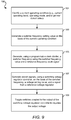
- FIG. 9 is an operational flow diagram of the process of selecting a switcher frequency for a switching voltage regulator utilizing a switching voltage regulator controller in accordance with a preferred embodiment.
- Operation flow diagram 100 starts with processor 70 identifying the current operating condition (e.g., current operating band, operating mode, and/or jammer detect value) (block 101).
- Processor 70 then generates a switcher frequency setting value on the basis of the current operating condition (block 103).
- Programmable clock divider 64 receives and processes the switcher frequency setting value in combination with reference frequency clock signal, REF_CLK, and generates the desired switching frequency (block 105).
- REF_CLK reference frequency clock signal
- Switching voltage regulator controller 63 receives the switching frequency from programmable clock divider 64, the voltage setting value, for example, from processor 70, and the signal from the reference voltage regulator 62, to generate switch signals (block 107).
- the switch signals are used to toggle switches (61a, 61b) which have the effect of regulating the output voltage of switching voltage regulator 40 (block 109).
- the operation flow diagram 100 may restart if the current operating condition changes (back to block 101).
- a more specific operation flow diagram for a multi-band CDMA wireless communication device is further described below.
- FIG. 10 is an operational flow diagram of the process of selecting an optimal switcher frequency, Fsw, for the switching voltage regulator in different operating frequency bands for CDMA mode accordance with a preferred embodiment.
- Operation flow diagram 200 starts with a start block (block 201) followed by programming one or more registers within the transceiver 20 for the particular operating band to be used (block 203).
- programmable clock divider 64 in switching voltage regulator 40, is set to one of three different values 6, 7, or 8 such that the switcher frequency (Fsw) of switching voltage regulator 40 is equal to either 2.4 MHz (CDMA PCS band), 2.74 MHz (CDMA450/800 band), or 3.2 MHz (CDMA IMT band) based on a reference clock frequency signal, REF_CLK, of 19.2 MHz (block 205).
- the switcher frequency, Fsw is calculated based multiple parameters.
- Fsw must be greater than half of Fch to insure that the switching noise does not directly couple into the baseband I/Q analog signals as shown in FIG. 1 , 2 , 7 , and 8 .
- Table 1 below shows Fch for different operating modes. Additional operating modes may be included. Operational flow diagram 200 is simplified to one operating mode, CDMA. Additional criteria will require that the switcher frequency, Fsw, be adjusted to higher values when there is transmit signal leakage and/or jamming tones present at the receiver input.
- the second criterion is that the transmit RF channel leakage (in a full duplex system such as CDMA) not corrupt the receive RF channel.
- the RF LO Generation block 28 will be contaminated with switcher frequency voltage ripple and corresponding harmonic frequencies from switching voltage regulator 40. If a switcher frequency harmonic is at a frequency offset close to the frequency separation between transmit RF and receive RF channels, the particular switcher harmonic will mix with the transmit RF channel leakage at I/Q down-converter 55 (after the switcher frequency voltage ripple has coupled into the RF VCO 33 (RX_VCO and RX_LO signals) and generate receive signal processing interference.
- switcher frequency voltage ripple and corresponding harmonic frequencies can couple to RF VCO within the TX LO Generation block 37 and create spurious content in the output of transmit signal processing block 22 of transceiver 20. This transmit spurious content can fall within the receive RF channel and create receive RF channel interference.
- the third criterion is based on the presence of jamming interference close in frequency to the desired receive RF channel.
- the fundamental switcher frequency (coupled onto RF VCO 33) can mix with the offset jamming tones (FJ1 at RF, J1 at baseband of FIG. 8 ) to create interference within the receive baseband channel bandwidth (RX_BB of FIG. 8 ) that cannot be filtered out or eliminated.
- the receive signal processing block 24 jamming specifications for different operating bands and modes may be applied such that the wireless device complies with the published minimum performance standards.
- the jammer frequency offsets from the desired RX RF channel (J1 offset for single-tone tests or J1 + J2 offsets for two-tone tests) are specified per the following operating bands as follows in Table 3.
- the switcher frequency may be adjusted such that Fsw > (J1 or J2) + Fch/2.
- J1 or J2 frequency offsets may be chosen from Table 3 for the above Fsw formula.
- the presence of jamming interference takes priority over TX signal leakage (second criterion) if there is no switcher frequency that satisfies both the second or third criteria.
- optimal switcher frequencies, Fsw may be calculated for multiple operating conditions in CDMA mode and stored as shown in Table 4 below.
- 2.4 MHz is generated by dividing 19.2 MHz by 8
- 2.74 MHz is generated by dividing 19.2 MHz by 7
- 3.2 MHz is generated by dividing 19.2 MHz by 6.
- the switcher frequency values of 6, 7, and 8 are selected for different CDMA frequency bands with and without jammers. Table 4.
- jamming detection circuit 59 is either polled or used as an interrupt (block 107).
- jammer detect signal is active (high logic level) in CDMA-PCS mode (according to Table 4)
- the switcher frequency (Fsw) is changed from 2.4 MHz to 2.74 MHz (block 109) by changing the switcher frequency value from 8 to 7.
- switcher frequency (Fsw) will be changed back to 2.4 MHz by changing the switcher frequency value to 8 (block 105 repeated) and jamming detection circuit 59 will continue monitoring (block 107, etc).
- Other switcher frequencies may be used depending on the available reference clock frequency signal, REF_CLK, and divider ratios for programmable clock divider 64 such that the three criteria are optimally met.
- signals may be represented using any of a variety of different techniques.
- data, instructions, signals that may be referenced throughout the above description may be represented by voltages, currents, electromagnetic waves, magnetic fields or particles, or any combination thereof.
- radio frequency or analog circuit blocks described in connection with the disclosure herein may be implemented in a variety of different circuit topologies, on one or more integrated circuits, separate from or in combination with logic circuits and systems while performing the same functions described in the present disclosure.
- DSP digital signal processor
- ASIC application specific integrated circuit
- FPGA field programmable gate array
- a general-purpose processor may be a microprocessor, but in the alternative, the processor may be any conventional processor, controller, microcontroller, or state machine.
- a processor may also be implemented as a combination of computing devices, e.g., a combination of a DSP and a microprocessor, a plurality of microprocessors, one or more microprocessors in conjunction with a DSP core, or any other such configuration.
- a software module may reside in RAM memory, flash memory, ROM memory, EPROM memory, EEPROM memory, registers, hard disk, a removable disk, a CD-ROM, or any other form of storage medium known in the art.
- An exemplary storage medium is coupled to the processor such that the processor may read information from, and write information to, the storage medium.
- the storage medium may be integral to the processor.
- the processor and the storage medium may reside in an ASIC.
- the ASIC may reside in a user terminal.
- the processor and the storage medium may reside as discrete components in a user terminal.
Priority Applications (1)
| Application Number | Priority Date | Filing Date | Title |
|---|---|---|---|
| EP14181948.2A EP2827505B1 (en) | 2008-12-04 | 2009-12-04 | Switching voltage regulator with frequency selection |
Applications Claiming Priority (2)
| Application Number | Priority Date | Filing Date | Title |
|---|---|---|---|
| US12/327,990 US8294445B2 (en) | 2008-12-04 | 2008-12-04 | Switching voltage regulator with frequency selection |
| PCT/US2009/066882 WO2010065934A1 (en) | 2008-12-04 | 2009-12-04 | Switching voltage regulator with frequency selection |
Related Child Applications (2)
| Application Number | Title | Priority Date | Filing Date |
|---|---|---|---|
| EP14181948.2A Division-Into EP2827505B1 (en) | 2008-12-04 | 2009-12-04 | Switching voltage regulator with frequency selection |
| EP14181948.2A Division EP2827505B1 (en) | 2008-12-04 | 2009-12-04 | Switching voltage regulator with frequency selection |
Publications (2)
| Publication Number | Publication Date |
|---|---|
| EP2371067A1 EP2371067A1 (en) | 2011-10-05 |
| EP2371067B1 true EP2371067B1 (en) | 2016-02-10 |
Family
ID=41718273
Family Applications (2)
| Application Number | Title | Priority Date | Filing Date |
|---|---|---|---|
| EP14181948.2A Active EP2827505B1 (en) | 2008-12-04 | 2009-12-04 | Switching voltage regulator with frequency selection |
| EP09796513.1A Active EP2371067B1 (en) | 2008-12-04 | 2009-12-04 | Switching voltage regulator with frequency selection |
Family Applications Before (1)
| Application Number | Title | Priority Date | Filing Date |
|---|---|---|---|
| EP14181948.2A Active EP2827505B1 (en) | 2008-12-04 | 2009-12-04 | Switching voltage regulator with frequency selection |
Country Status (8)
| Country | Link |
|---|---|
| US (1) | US8294445B2 (ja) |
| EP (2) | EP2827505B1 (ja) |
| JP (2) | JP2012511285A (ja) |
| KR (1) | KR101263814B1 (ja) |
| CN (2) | CN103997211B (ja) |
| IN (1) | IN2014CN04321A (ja) |
| TW (2) | TWI533627B (ja) |
| WO (1) | WO2010065934A1 (ja) |
Families Citing this family (23)
| Publication number | Priority date | Publication date | Assignee | Title |
|---|---|---|---|---|
| DE102007046341A1 (de) * | 2007-09-27 | 2009-04-23 | Infineon Technologies Ag | Schaltungsanordnung zum Verarbeiten eines hochfrequenten Signals |
| EP2583377A1 (en) | 2010-06-21 | 2013-04-24 | Telefonaktiebolaget LM Ericsson (publ) | A coordinated power converter system |
| US20120154958A1 (en) * | 2010-12-20 | 2012-06-21 | Nexergy, Inc. | Use of a jfet as a failsafe shutdown controller |
| US8963527B2 (en) * | 2010-12-31 | 2015-02-24 | Integrated Device Technology Inc. | EMI mitigation of power converters by modulation of switch control signals |
| FR2992073B1 (fr) * | 2012-06-19 | 2014-07-11 | Commissariat Energie Atomique | Dispositif d'alimentation d'un circuit electronique |
| US9003209B2 (en) * | 2012-06-29 | 2015-04-07 | Intel Corporation | Efficient integrated switching voltage regulator comprising switches coupled to bridge drivers to provide regulated power supply to power domains |
| US8975887B2 (en) | 2012-07-08 | 2015-03-10 | R2 Semiconductor, Inc. | Suppressing oscillations in an output of a switched power converter |
| US9014637B1 (en) * | 2013-09-27 | 2015-04-21 | Intel Corporation | Dynamic switching frequency control of an on-chip or integrated voltage regulator |
| US10439491B2 (en) * | 2014-02-14 | 2019-10-08 | Telefonaktiebolaget Lm Ericsson (Publ) | Power supply electronic circuit with IBC to control current ripple |
| TWI551070B (zh) | 2015-05-08 | 2016-09-21 | 和碩聯合科技股份有限公司 | 可攜式電子裝置 |
| TWI609572B (zh) * | 2015-05-15 | 2017-12-21 | 絡達科技股份有限公司 | 射頻切換模組的控制方法 |
| CN107690753B (zh) | 2015-05-29 | 2020-07-14 | 马克西姆综合产品公司 | 低功率超宽带发射机 |
| JP6546054B2 (ja) * | 2015-09-25 | 2019-07-17 | ルネサスエレクトロニクス株式会社 | 無線通信装置及び無線通信方法 |
| US9898218B2 (en) | 2016-02-05 | 2018-02-20 | International Business Machines Corporation | Memory system with switchable operating bands |
| EP3229357B1 (en) * | 2016-04-08 | 2020-08-19 | Nxp B.V. | Charge pump with reference voltage modification for avoiding specific frequencies |
| CN105978326B (zh) * | 2016-06-20 | 2018-07-03 | 浙江大学 | 开关频率实时调节的光纤陀螺内置dc-dc电源 |
| DE102016212656B4 (de) * | 2016-07-12 | 2019-05-29 | Hanon Systems | Steuervorrichtung für einen elektrischen Kompressor |
| US9923520B1 (en) | 2016-09-21 | 2018-03-20 | Qualcomm Incorporated | Switching power supply for RF power amplifiers |
| TWI607623B (zh) * | 2016-10-07 | 2017-12-01 | 新唐科技股份有限公司 | 切換式電容型直流轉直流轉換器及其控制方法 |
| US10218366B1 (en) | 2017-11-27 | 2019-02-26 | Linear Technology Holding Llc | Phase locked loop calibration for synchronizing non-constant frequency switching regulators |
| CN108539973B (zh) * | 2018-05-18 | 2019-12-31 | 深圳市华星光电技术有限公司 | Tft-lcd显示器及其驱动电路、开关电源 |
| CN112469112B (zh) * | 2020-11-25 | 2023-03-21 | Oppo(重庆)智能科技有限公司 | 频率控制方法、装置、射频系统及通信设备 |
| CN114978229A (zh) * | 2022-06-28 | 2022-08-30 | 维沃移动通信有限公司 | 射频控制方法、装置及电子设备 |
Family Cites Families (32)
| Publication number | Priority date | Publication date | Assignee | Title |
|---|---|---|---|---|
| US4580107A (en) * | 1984-06-06 | 1986-04-01 | The United States Of America As Represented By The Secretary Of The Air Force | Phase lock acquisition system having FLL for coarse tuning and PLL for fine tuning |
| US4870699A (en) * | 1986-03-26 | 1989-09-26 | General Electric Company | Method and apparatus for controlling the frequency of operation and at least one further variable operating parameter of a radio communications device |
| US4879758A (en) * | 1987-01-02 | 1989-11-07 | Motorola, Inc. | Communication receiver system having a decoder operating at variable frequencies |
| US5150361A (en) * | 1989-01-23 | 1992-09-22 | Motorola, Inc. | Energy saving protocol for a TDM radio |
| US5363419A (en) * | 1992-04-24 | 1994-11-08 | Advanced Micro Devices, Inc. | Dual phase-locked-loop having forced mid range fine control zero at handover |
| JPH05315980A (ja) * | 1992-05-08 | 1993-11-26 | Victor Co Of Japan Ltd | 無線受信機 |
| JPH0870258A (ja) * | 1994-09-30 | 1996-03-12 | Matsushita Electric Ind Co Ltd | 無線装置 |
| US5773966A (en) * | 1995-11-06 | 1998-06-30 | General Electric Company | Dual-mode, high-efficiency dc-dc converter useful for portable battery-operated equipment |
| JPH11332230A (ja) | 1998-05-07 | 1999-11-30 | Alinco Inc | スイッチング電源 |
| US6204649B1 (en) | 2000-03-16 | 2001-03-20 | Micrel Incorporated | PWM regulator with varying operating frequency for reduced EMI |
| TW519792B (en) | 2000-08-30 | 2003-02-01 | Cirrus Logic Inc | Circuits and methods for reducing interference from switched mode circuits |
| US7058374B2 (en) | 2002-10-15 | 2006-06-06 | Skyworks Solutions, Inc. | Low noise switching voltage regulator |
| US7130602B2 (en) | 2002-10-31 | 2006-10-31 | Qualcomm Incorporated | Dynamically programmable receiver |
| US20040090802A1 (en) | 2002-11-01 | 2004-05-13 | Sierra Wireless, Inc., A Canadian Corporation | Noise suppression in switching power supplies |
| US7583555B2 (en) * | 2003-04-11 | 2009-09-01 | Qualcomm Incorporated | Robust and Efficient dynamic voltage scaling for portable devices |
| JP4461842B2 (ja) | 2004-03-09 | 2010-05-12 | 株式会社デンソー | スイッチングレギュレータ及びスイッチングレギュレータの制御方法 |
| US7218531B2 (en) | 2004-04-05 | 2007-05-15 | Elster Electricity, Llc | Switching regulator with reduced conducted emissions |
| US7283851B2 (en) | 2004-04-05 | 2007-10-16 | Qualcomm Incorporated | Power saving mode for receiver circuit blocks based on transmitter activity |
| US7362191B2 (en) | 2004-04-29 | 2008-04-22 | Linear Technology Corporation | Methods and circuits for frequency modulation that reduce the spectral noise of switching regulators |
| JP4738329B2 (ja) * | 2004-05-28 | 2011-08-03 | パナソニック株式会社 | マルチモード制御局、無線通信システム、無線局及び無線通信制御方法 |
| JP4341753B2 (ja) * | 2004-08-02 | 2009-10-07 | 国立大学法人 電気通信大学 | ロバストディジタル制御器およびその設計装置 |
| US7015763B1 (en) * | 2004-08-30 | 2006-03-21 | Nokia Corporation | Digital tuning of a voltage controlled oscillator of a phase locked loop |
| JP2006094656A (ja) | 2004-09-24 | 2006-04-06 | Sharp Corp | スイッチング電源 |
| CN100508388C (zh) * | 2004-10-09 | 2009-07-01 | 深圳迈瑞生物医疗电子股份有限公司 | 一种工业频率自动跟踪的滤波方法与装置、心电检测设备 |
| US7190291B2 (en) * | 2005-01-05 | 2007-03-13 | Artesyn Technologies, Inc. | Programmable error amplifier for sensing voltage error in the feedback path of digitially programmable voltage sources |
| US7805170B2 (en) | 2005-03-30 | 2010-09-28 | St-Ericsson Sa | System and method for efficient power supply regulation compatible with radio frequency operation |
| US7239115B2 (en) * | 2005-04-04 | 2007-07-03 | Power-One, Inc. | Digital pulse width modulation controller with preset filter coefficients |
| US7323944B2 (en) * | 2005-04-11 | 2008-01-29 | Qualcomm Incorporated | PLL lock management system |
| US7312664B2 (en) * | 2005-08-24 | 2007-12-25 | Avago Technologies General Ip Pte Ltd | Methods and apparatuses for testing a voltage-controlled oscillator (VCO) to verify operation across supply voltage and/or temperature |
| JP2007208718A (ja) * | 2006-02-02 | 2007-08-16 | Kenwood Corp | スイッチング電源装置 |
| US7521907B2 (en) * | 2006-03-06 | 2009-04-21 | Enpirion, Inc. | Controller for a power converter and method of operating the same |
| US8239694B2 (en) * | 2008-03-31 | 2012-08-07 | Qualcomm, Incorporated | Dynamic frequency scaling of a switched mode power supply |
-
2008
- 2008-12-04 US US12/327,990 patent/US8294445B2/en active Active
-
2009
- 2009-12-04 TW TW103119281A patent/TWI533627B/zh active
- 2009-12-04 TW TW98141652A patent/TWI472166B/zh active
- 2009-12-04 EP EP14181948.2A patent/EP2827505B1/en active Active
- 2009-12-04 EP EP09796513.1A patent/EP2371067B1/en active Active
- 2009-12-04 CN CN201410158748.4A patent/CN103997211B/zh active Active
- 2009-12-04 CN CN200980148539.9A patent/CN102239642B/zh active Active
- 2009-12-04 JP JP2011539765A patent/JP2012511285A/ja active Pending
- 2009-12-04 KR KR1020117015423A patent/KR101263814B1/ko active IP Right Grant
- 2009-12-04 WO PCT/US2009/066882 patent/WO2010065934A1/en active Application Filing
-
2013
- 2013-12-06 JP JP2013253675A patent/JP5805738B2/ja active Active
-
2014
- 2014-06-11 IN IN4321CHN2014 patent/IN2014CN04321A/en unknown
Also Published As
| Publication number | Publication date |
|---|---|
| TW201436480A (zh) | 2014-09-16 |
| CN102239642A (zh) | 2011-11-09 |
| TW201037982A (en) | 2010-10-16 |
| CN103997211A (zh) | 2014-08-20 |
| EP2827505A1 (en) | 2015-01-21 |
| US8294445B2 (en) | 2012-10-23 |
| WO2010065934A1 (en) | 2010-06-10 |
| EP2827505B1 (en) | 2018-11-28 |
| TWI533627B (zh) | 2016-05-11 |
| TWI472166B (zh) | 2015-02-01 |
| CN102239642B (zh) | 2014-05-28 |
| US20100141233A1 (en) | 2010-06-10 |
| KR20110102399A (ko) | 2011-09-16 |
| EP2371067A1 (en) | 2011-10-05 |
| JP5805738B2 (ja) | 2015-11-04 |
| JP2014060921A (ja) | 2014-04-03 |
| KR101263814B1 (ko) | 2013-05-13 |
| IN2014CN04321A (ja) | 2015-09-04 |
| JP2012511285A (ja) | 2012-05-17 |
| CN103997211B (zh) | 2017-05-10 |
Similar Documents
| Publication | Publication Date | Title |
|---|---|---|
| EP2371067B1 (en) | Switching voltage regulator with frequency selection | |
| US8145149B2 (en) | Operating a voltage regulator at a switching frequency selected to reduce spurious signals | |
| KR101717224B1 (ko) | 상이한 라디오 액세스 기술들의 다수의 무선 통신 시스템들에 대한 동시 통신을 위한 방법 및 장치 | |
| US6768376B2 (en) | Dual mode class D amplifiers | |
| US9590644B2 (en) | Managing spurs in a radio frequency circuit | |
| US20070218851A1 (en) | Multiple band RF transmitters and receivers having independently variable RF and IF local oscillators and independent high-side and low-side RF local oscillators | |
| US20160013816A1 (en) | Adaptive/Configurable Intermediate Frequency (IF) Wireless Receiver And Bluetooth Device Using The Same | |
| US7405630B2 (en) | Frequency synthesizer with improved spurious performance | |
| US20100237951A1 (en) | Frequency calibration of radio frequency oscillators | |
| US10128857B1 (en) | System, apparatus and method for programmably controlling generation of a notch at a radio frequency using arbitrary pulse pairing | |
| US6181212B1 (en) | Phase locked loop for generating two disparate, variable frequency signals | |
| WO2014107163A1 (en) | Systems and methods for frequency synthesis to improve coexistence | |
| US20130271229A1 (en) | Method and apparatus for local oscillator | |
| Bhagavatula et al. | 13.3 A SAW-less reconfigurable multimode transmitter with a voltage-mode harmonic-reject mixer in 14nm FinFET CMOS | |
| Im et al. | A fully integrated 0.2 V 802.11 ba wake-up receiver with-91.5 dBm sensitivity | |
| Analui et al. | A 50 MHz–6 GHz, 2× 2 MIMO, reconfigurable architecture, software-defined radio in 130nm CMOS | |
| US10447282B2 (en) | Phase locked loop (PLL) | |
| EP2659590B1 (en) | Transceiver with sub-sampling based frequency synthesizer | |
| Lai et al. | A world-band triple-mode 802.11 a/b/g SOC in 130-nm CMOS | |
| US8242857B2 (en) | Single side band mixer and local oscillator having the same | |
| Wilkins | Polaris Total Radio/sup TM/, a highly integrated RF solution for GSM/GPRS and EDGE | |
| Lange et al. | A Low-Pin-Count 900-MHz FSK/ASK Transmitter | |
| Chen et al. | A compact-size dual-band (tri-mode) receiver front-end with switched harmonic mixer and technology scaling |
Legal Events
| Date | Code | Title | Description |
|---|---|---|---|
| PUAI | Public reference made under article 153(3) epc to a published international application that has entered the european phase |
Free format text: ORIGINAL CODE: 0009012 |
|
| 17P | Request for examination filed |
Effective date: 20110629 |
|
| AK | Designated contracting states |
Kind code of ref document: A1 Designated state(s): AT BE BG CH CY CZ DE DK EE ES FI FR GB GR HR HU IE IS IT LI LT LU LV MC MK MT NL NO PL PT RO SE SI SK SM TR |
|
| DAX | Request for extension of the european patent (deleted) | ||
| 17Q | First examination report despatched |
Effective date: 20131001 |
|
| GRAP | Despatch of communication of intention to grant a patent |
Free format text: ORIGINAL CODE: EPIDOSNIGR1 |
|
| INTG | Intention to grant announced |
Effective date: 20150703 |
|
| GRAS | Grant fee paid |
Free format text: ORIGINAL CODE: EPIDOSNIGR3 |
|
| GRAA | (expected) grant |
Free format text: ORIGINAL CODE: 0009210 |
|
| AK | Designated contracting states |
Kind code of ref document: B1 Designated state(s): AT BE BG CH CY CZ DE DK EE ES FI FR GB GR HR HU IE IS IT LI LT LU LV MC MK MT NL NO PL PT RO SE SI SK SM TR |
|
| REG | Reference to a national code |
Ref country code: GB Ref legal event code: FG4D |
|
| REG | Reference to a national code |
Ref country code: AT Ref legal event code: REF Ref document number: 775088 Country of ref document: AT Kind code of ref document: T Effective date: 20160215 Ref country code: CH Ref legal event code: EP |
|
| REG | Reference to a national code |
Ref country code: IE Ref legal event code: FG4D |
|
| REG | Reference to a national code |
Ref country code: DE Ref legal event code: R096 Ref document number: 602009036243 Country of ref document: DE |
|
| REG | Reference to a national code |
Ref country code: LT Ref legal event code: MG4D |
|
| REG | Reference to a national code |
Ref country code: NL Ref legal event code: MP Effective date: 20160210 |
|
| REG | Reference to a national code |
Ref country code: AT Ref legal event code: MK05 Ref document number: 775088 Country of ref document: AT Kind code of ref document: T Effective date: 20160210 |
|
| PG25 | Lapsed in a contracting state [announced via postgrant information from national office to epo] |
Ref country code: HR Free format text: LAPSE BECAUSE OF FAILURE TO SUBMIT A TRANSLATION OF THE DESCRIPTION OR TO PAY THE FEE WITHIN THE PRESCRIBED TIME-LIMIT Effective date: 20160210 Ref country code: IT Free format text: LAPSE BECAUSE OF FAILURE TO SUBMIT A TRANSLATION OF THE DESCRIPTION OR TO PAY THE FEE WITHIN THE PRESCRIBED TIME-LIMIT Effective date: 20160210 Ref country code: ES Free format text: LAPSE BECAUSE OF FAILURE TO SUBMIT A TRANSLATION OF THE DESCRIPTION OR TO PAY THE FEE WITHIN THE PRESCRIBED TIME-LIMIT Effective date: 20160210 Ref country code: FI Free format text: LAPSE BECAUSE OF FAILURE TO SUBMIT A TRANSLATION OF THE DESCRIPTION OR TO PAY THE FEE WITHIN THE PRESCRIBED TIME-LIMIT Effective date: 20160210 Ref country code: GR Free format text: LAPSE BECAUSE OF FAILURE TO SUBMIT A TRANSLATION OF THE DESCRIPTION OR TO PAY THE FEE WITHIN THE PRESCRIBED TIME-LIMIT Effective date: 20160511 Ref country code: NO Free format text: LAPSE BECAUSE OF FAILURE TO SUBMIT A TRANSLATION OF THE DESCRIPTION OR TO PAY THE FEE WITHIN THE PRESCRIBED TIME-LIMIT Effective date: 20160510 |
|
| PG25 | Lapsed in a contracting state [announced via postgrant information from national office to epo] |
Ref country code: IS Free format text: LAPSE BECAUSE OF FAILURE TO SUBMIT A TRANSLATION OF THE DESCRIPTION OR TO PAY THE FEE WITHIN THE PRESCRIBED TIME-LIMIT Effective date: 20160610 Ref country code: PT Free format text: LAPSE BECAUSE OF FAILURE TO SUBMIT A TRANSLATION OF THE DESCRIPTION OR TO PAY THE FEE WITHIN THE PRESCRIBED TIME-LIMIT Effective date: 20160613 Ref country code: NL Free format text: LAPSE BECAUSE OF FAILURE TO SUBMIT A TRANSLATION OF THE DESCRIPTION OR TO PAY THE FEE WITHIN THE PRESCRIBED TIME-LIMIT Effective date: 20160210 Ref country code: PL Free format text: LAPSE BECAUSE OF FAILURE TO SUBMIT A TRANSLATION OF THE DESCRIPTION OR TO PAY THE FEE WITHIN THE PRESCRIBED TIME-LIMIT Effective date: 20160210 Ref country code: LV Free format text: LAPSE BECAUSE OF FAILURE TO SUBMIT A TRANSLATION OF THE DESCRIPTION OR TO PAY THE FEE WITHIN THE PRESCRIBED TIME-LIMIT Effective date: 20160210 Ref country code: LT Free format text: LAPSE BECAUSE OF FAILURE TO SUBMIT A TRANSLATION OF THE DESCRIPTION OR TO PAY THE FEE WITHIN THE PRESCRIBED TIME-LIMIT Effective date: 20160210 Ref country code: AT Free format text: LAPSE BECAUSE OF FAILURE TO SUBMIT A TRANSLATION OF THE DESCRIPTION OR TO PAY THE FEE WITHIN THE PRESCRIBED TIME-LIMIT Effective date: 20160210 Ref country code: SE Free format text: LAPSE BECAUSE OF FAILURE TO SUBMIT A TRANSLATION OF THE DESCRIPTION OR TO PAY THE FEE WITHIN THE PRESCRIBED TIME-LIMIT Effective date: 20160210 |
|
| PG25 | Lapsed in a contracting state [announced via postgrant information from national office to epo] |
Ref country code: EE Free format text: LAPSE BECAUSE OF FAILURE TO SUBMIT A TRANSLATION OF THE DESCRIPTION OR TO PAY THE FEE WITHIN THE PRESCRIBED TIME-LIMIT Effective date: 20160210 Ref country code: DK Free format text: LAPSE BECAUSE OF FAILURE TO SUBMIT A TRANSLATION OF THE DESCRIPTION OR TO PAY THE FEE WITHIN THE PRESCRIBED TIME-LIMIT Effective date: 20160210 |
|
| REG | Reference to a national code |
Ref country code: DE Ref legal event code: R097 Ref document number: 602009036243 Country of ref document: DE |
|
| PG25 | Lapsed in a contracting state [announced via postgrant information from national office to epo] |
Ref country code: CZ Free format text: LAPSE BECAUSE OF FAILURE TO SUBMIT A TRANSLATION OF THE DESCRIPTION OR TO PAY THE FEE WITHIN THE PRESCRIBED TIME-LIMIT Effective date: 20160210 Ref country code: RO Free format text: LAPSE BECAUSE OF FAILURE TO SUBMIT A TRANSLATION OF THE DESCRIPTION OR TO PAY THE FEE WITHIN THE PRESCRIBED TIME-LIMIT Effective date: 20160210 Ref country code: SM Free format text: LAPSE BECAUSE OF FAILURE TO SUBMIT A TRANSLATION OF THE DESCRIPTION OR TO PAY THE FEE WITHIN THE PRESCRIBED TIME-LIMIT Effective date: 20160210 Ref country code: SK Free format text: LAPSE BECAUSE OF FAILURE TO SUBMIT A TRANSLATION OF THE DESCRIPTION OR TO PAY THE FEE WITHIN THE PRESCRIBED TIME-LIMIT Effective date: 20160210 |
|
| PLBE | No opposition filed within time limit |
Free format text: ORIGINAL CODE: 0009261 |
|
| STAA | Information on the status of an ep patent application or granted ep patent |
Free format text: STATUS: NO OPPOSITION FILED WITHIN TIME LIMIT |
|
| PG25 | Lapsed in a contracting state [announced via postgrant information from national office to epo] |
Ref country code: BE Free format text: LAPSE BECAUSE OF FAILURE TO SUBMIT A TRANSLATION OF THE DESCRIPTION OR TO PAY THE FEE WITHIN THE PRESCRIBED TIME-LIMIT Effective date: 20160210 |
|
| 26N | No opposition filed |
Effective date: 20161111 |
|
| PG25 | Lapsed in a contracting state [announced via postgrant information from national office to epo] |
Ref country code: SI Free format text: LAPSE BECAUSE OF FAILURE TO SUBMIT A TRANSLATION OF THE DESCRIPTION OR TO PAY THE FEE WITHIN THE PRESCRIBED TIME-LIMIT Effective date: 20160210 Ref country code: BG Free format text: LAPSE BECAUSE OF FAILURE TO SUBMIT A TRANSLATION OF THE DESCRIPTION OR TO PAY THE FEE WITHIN THE PRESCRIBED TIME-LIMIT Effective date: 20160510 |
|
| REG | Reference to a national code |
Ref country code: CH Ref legal event code: PL |
|
| PG25 | Lapsed in a contracting state [announced via postgrant information from national office to epo] |
Ref country code: MC Free format text: LAPSE BECAUSE OF FAILURE TO SUBMIT A TRANSLATION OF THE DESCRIPTION OR TO PAY THE FEE WITHIN THE PRESCRIBED TIME-LIMIT Effective date: 20160210 |
|
| REG | Reference to a national code |
Ref country code: FR Ref legal event code: ST Effective date: 20170831 |
|
| REG | Reference to a national code |
Ref country code: IE Ref legal event code: MM4A |
|
| PG25 | Lapsed in a contracting state [announced via postgrant information from national office to epo] |
Ref country code: LI Free format text: LAPSE BECAUSE OF NON-PAYMENT OF DUE FEES Effective date: 20161231 Ref country code: LU Free format text: LAPSE BECAUSE OF NON-PAYMENT OF DUE FEES Effective date: 20161204 Ref country code: CH Free format text: LAPSE BECAUSE OF NON-PAYMENT OF DUE FEES Effective date: 20161231 Ref country code: FR Free format text: LAPSE BECAUSE OF NON-PAYMENT OF DUE FEES Effective date: 20170102 |
|
| PG25 | Lapsed in a contracting state [announced via postgrant information from national office to epo] |
Ref country code: IE Free format text: LAPSE BECAUSE OF NON-PAYMENT OF DUE FEES Effective date: 20161204 |
|
| PG25 | Lapsed in a contracting state [announced via postgrant information from national office to epo] |
Ref country code: HU Free format text: LAPSE BECAUSE OF FAILURE TO SUBMIT A TRANSLATION OF THE DESCRIPTION OR TO PAY THE FEE WITHIN THE PRESCRIBED TIME-LIMIT; INVALID AB INITIO Effective date: 20091204 Ref country code: CY Free format text: LAPSE BECAUSE OF FAILURE TO SUBMIT A TRANSLATION OF THE DESCRIPTION OR TO PAY THE FEE WITHIN THE PRESCRIBED TIME-LIMIT Effective date: 20160210 |
|
| PG25 | Lapsed in a contracting state [announced via postgrant information from national office to epo] |
Ref country code: MK Free format text: LAPSE BECAUSE OF FAILURE TO SUBMIT A TRANSLATION OF THE DESCRIPTION OR TO PAY THE FEE WITHIN THE PRESCRIBED TIME-LIMIT Effective date: 20160210 Ref country code: TR Free format text: LAPSE BECAUSE OF FAILURE TO SUBMIT A TRANSLATION OF THE DESCRIPTION OR TO PAY THE FEE WITHIN THE PRESCRIBED TIME-LIMIT Effective date: 20160210 |
|
| PG25 | Lapsed in a contracting state [announced via postgrant information from national office to epo] |
Ref country code: MT Free format text: LAPSE BECAUSE OF NON-PAYMENT OF DUE FEES Effective date: 20161204 |
|
| PGFP | Annual fee paid to national office [announced via postgrant information from national office to epo] |
Ref country code: GB Payment date: 20231108 Year of fee payment: 15 |
|
| PGFP | Annual fee paid to national office [announced via postgrant information from national office to epo] |
Ref country code: DE Payment date: 20231108 Year of fee payment: 15 |