EP2369737A1 - Oszillationsschaltung - Google Patents
Oszillationsschaltung Download PDFInfo
- Publication number
- EP2369737A1 EP2369737A1 EP09833200A EP09833200A EP2369737A1 EP 2369737 A1 EP2369737 A1 EP 2369737A1 EP 09833200 A EP09833200 A EP 09833200A EP 09833200 A EP09833200 A EP 09833200A EP 2369737 A1 EP2369737 A1 EP 2369737A1
- Authority
- EP
- European Patent Office
- Prior art keywords
- oscillator
- energizing pulse
- oscillation circuit
- energizing
- pulse generator
- Prior art date
- Legal status (The legal status is an assumption and is not a legal conclusion. Google has not performed a legal analysis and makes no representation as to the accuracy of the status listed.)
- Withdrawn
Links
Images

Classifications
-
- H—ELECTRICITY
- H03—ELECTRONIC CIRCUITRY
- H03B—GENERATION OF OSCILLATIONS, DIRECTLY OR BY FREQUENCY-CHANGING, BY CIRCUITS EMPLOYING ACTIVE ELEMENTS WHICH OPERATE IN A NON-SWITCHING MANNER; GENERATION OF NOISE BY SUCH CIRCUITS
- H03B5/00—Generation of oscillations using amplifier with regenerative feedback from output to input
- H03B5/30—Generation of oscillations using amplifier with regenerative feedback from output to input with frequency-determining element being electromechanical resonator
-
- G—PHYSICS
- G01—MEASURING; TESTING
- G01F—MEASURING VOLUME, VOLUME FLOW, MASS FLOW OR LIQUID LEVEL; METERING BY VOLUME
- G01F1/00—Measuring the volume flow or mass flow of fluid or fluent solid material wherein the fluid passes through a meter in a continuous flow
- G01F1/66—Measuring the volume flow or mass flow of fluid or fluent solid material wherein the fluid passes through a meter in a continuous flow by measuring frequency, phase shift or propagation time of electromagnetic or other waves, e.g. using ultrasonic flowmeters
- G01F1/667—Arrangements of transducers for ultrasonic flowmeters; Circuits for operating ultrasonic flowmeters
-
- H—ELECTRICITY
- H03—ELECTRONIC CIRCUITRY
- H03B—GENERATION OF OSCILLATIONS, DIRECTLY OR BY FREQUENCY-CHANGING, BY CIRCUITS EMPLOYING ACTIVE ELEMENTS WHICH OPERATE IN A NON-SWITCHING MANNER; GENERATION OF NOISE BY SUCH CIRCUITS
- H03B5/00—Generation of oscillations using amplifier with regenerative feedback from output to input
- H03B5/02—Details
- H03B5/06—Modifications of generator to ensure starting of oscillations
-
- H—ELECTRICITY
- H03—ELECTRONIC CIRCUITRY
- H03K—PULSE TECHNIQUE
- H03K3/00—Circuits for generating electric pulses; Monostable, bistable or multistable circuits
- H03K3/01—Details
- H03K3/014—Modifications of generator to ensure starting of oscillations
-
- H—ELECTRICITY
- H03—ELECTRONIC CIRCUITRY
- H03K—PULSE TECHNIQUE
- H03K3/00—Circuits for generating electric pulses; Monostable, bistable or multistable circuits
- H03K3/02—Generators characterised by the type of circuit or by the means used for producing pulses
- H03K3/027—Generators characterised by the type of circuit or by the means used for producing pulses by the use of logic circuits, with internal or external positive feedback
- H03K3/03—Astable circuits
- H03K3/0307—Stabilisation of output, e.g. using crystal
Definitions
- the present invention relates to an oscillation circuit for shortening the time for driving of an oscillation circuit that uses an oscillator until stable oscillation is reached.
- ultrasonic flow meters are intermittently operated so far as the accuracy of the flow meters permits.
- Ultrasonic flow meters measure the velocity of a flow based on measurement of propagation time of ultrasonic waves, and calculate the quantity of flow by multiplying the flow rate with the cross-sectional area of the piping.
- Propagation time of ultrasonic waves is measured by using pulses of a fixed frequency and counting the number of pulses between transmission and reception of the ultrasonic waves, and multiplying the pulse frequency by the number of pulses.
- it is power-thrifty if these pulses can be stopped when flow rate measurement is stopped.
- an oscillation circuit containing a ceramic oscillator or a crystal oscillator is used for generating pulses of the fixed frequency to be used for propagation time measurement of ultrasonic waves.
- the oscillation circuit comprises a crystal oscillator, a capacitor to insure reliability of oscillation, a resistor, and an amplifier.
- the ring oscillator has a current source having temperature correction capability.
- a switching circuit lies between the basic oscillation circuit and the ring oscillator.
- Hot start This method of advancing start of the oscillation circuit by giving a pulse to the oscillation circuit from outside at an early stage of start of the oscillation circuit is called "hot start” for convenience.
- Patent Literature 2 There also was an ultrasonic flow meter that intermittently operated, for the purpose of reducing electric power consumption, a oscillator for making pulses for measuring transmission time of ultrasonic waves, and was equipped with oscillation initiation means for advancing vibration of the oscillator (ref. Patent Literature 2, for example).
- Patent Literature 2 it is described that the method described in Patent Literature 1 is effective for intermittent operation of pulses to be used for measurement of transmission time of ultrasonic waves.
- the oscillation circuit of the present invention includes a oscillator having a resonant frequency, an amplifier connected to the oscillator, an energizing pulse generator for generating a energizing pulse of a frequency within a certain range including the resonant frequency, a switching unit for switching between connection and disconnection the energizing pulse generator and the oscillator, and the amplifier, and a motion command unit for sending a command signal to the energizing pulse generator for starting operation, where the switching unit connects the oscillator and the energizing pulse generator during a cycle, a half cycle, or plural cycles of the energizing pulse generated by the energizing pulse generator starting at a time when the motion command unit sends the motion signal.
- the energizing pulse generator With the oscillation circuit of such a structure, although the energizing pulse generator generates energizing pulses having a resonant frequency close to that of the oscillator, as the allowable frequency range of the energizing pulse becomes wide, hot start can be realized with a very simple circuit structure without calling for temperature correction function.
- Fig. 1 is a block diagram of the oscillation circuit in a preferred embodiment of the present invention.
- oscillation circuit 5 includes oscillator 1, amplifier 2, energizing pulse generator 3 for generating energizing pulses, and switching unit 4.
- switching unit 4 switches between connection and disconnection of energizing pulse generator 3, oscillator 1 and energizing pulse generator 3, and amplifier 2.
- oscillation circuit 5 includes an operation command unit not shown in Fig. 1 , and the operation command unit issues a command signal for start of operation to oscillator 1, amplifier 2, energizing pulse generator 3, and switching unit 4.
- the operation command unit is composed of a microcomputer.
- oscillator 1 a crystal oscillator or a ceramic oscillator, or a crystal oscillator or a ceramic oscillator added with a capacitor to stabilize their action is used.
- the acuity of resonance of impendance characteristic of ceramic oscillators is mild compared with crystal oscillators, it is more adequate to the present invention than crystal oscillators.
- the pulses obtained by vibrating at their resonant frequency are used for various applications.
- Fig. 2 is a circuit diagram of an oscillator of the oscillation circuit and an amplifier in an embodiment of the present invention.
- Fig. 2 is a circuit diagram showing oscillator 1 and amplifier 2 of oscillation circuit 5 shown in Fig. 1 .
- ceramic oscillator 1 a 4 MHz ceramic oscillator in RBRC-G series made by Kyocera Corporation is used, for example, and TC74HCU series and TC74HC series amplifiers made by Toshiba Semiconductor Company are used as the amplifier.
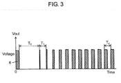
- Fig. 3 is a voltage waveform of output pulse Vout of the oscillation circuit in an embodiment of the present invention.
- Fig. 3 shows waveform of the output pulse Vout obtained by using oscillation circuit 5 shown in Fig. 1 and Fig. 2 .
- time 0 starting point
- motion command unit not shown
- amplifier 2 which is on standby by with electric power being supplied in advance.
- an energizing pulse is supplied from energizing pulse generator unit 3 to oscillator 1 and amplifier 2.
- Energizing pulse 6 is supplied by energizing pulse generator unit 3 and has a width of a half cycle of a frequency close to the resonant frequency (4MHz) of oscillator 1 in the case of Fig. 3 .
- energizing pulses are provided to oscillator 1 and amplifier 2 from energizing pulse generator 3 at such timing.
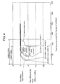
- Fig. 4 is a characteristic curve plotting periodic changes of the output pulse Vout of amplifier 2, in which the time difference until the energizing pulses finally stabilize (the period being 250ns because of use of a 4Hz oscillator) is plotted in the vertical axis as a function of time from the start of oscillation in the horizontal axis. Different characteristic curves are based on different energizing frequencies and wave numbers of the energizing pulses.
- wave number 1 indicates a case in which wave number 1 (a half cycle) was given at an energizing pulse frequency appropriate to the resonant frequency of oscillator 1, and the cycle of Vout pulse is stable at approximately 90 microseconds.
- wave number 1 indicates the case in which wave number 1 (half cycle) was given at an energizing pulse frequency shifted from the resonant frequency of oscillator 1, and it takes approximately 90 microseconds until the cycle of Vout pulse becomes stable.
- wave number 1 indicates a case in which wave number 1 (half a cycle) was given at an energizing pulse frequency shifted from the resonant frequency of oscillator 1, and it takes approximately 90 microseconds until the cycle of Vout pulse becomes stable.
- the resonance frequency 4 MHz of oscillator 1 3.5 MHz and 4.5 MHz are equivalent to -12.5% and +12.5%, respectively, and they represent the allowable frequency range of the energizing pulses. This is the key condition for attaining simple configuration in designing circuit configuration of energizing pulse generator 3 for making energizing pulses that are within the allowable frequency range.
- the 4 MHz oscillator can be a ring oscillator that uses delay of a device, or a CR oscillation circuit based on capacitor C and resistor R.
- energizing pulse generator unit 3 sets pulse frequency of energizing pulses using a capacitor and a resistor, or pulse width of the energizing pulses, and generates pulses (energizing pulses) of a frequency within a certain allowable frequency range including the resonant frequency.
- energizing pulse generator 3 can be designed with a simple circuit structure.
- energizing pulse generator 3 may set the pulse frequency of the energizing pulses or the pulse width of the energizing pulses using a ring oscillator. As a result, the construction of oscillation circuit 5 on a semiconductor device is made easy.
- switching unit 4 in such a manner that, in the initial period of driving (during the period of 1 cycle, half a cycle, or several cycles starting at the time an operation command was issued by the operation command unit) of driving the oscillator, the oscillator and the energizing pulse generator unit are connected, hot start can be realized with an extremely simple circuit structure without calling for temperature correction function.
- the circuit can be made simple without calling for external parts other than semiconductor IC as tolerance is large.
- a simple way of shortening the period from the start of driving of an oscillation circuit having an oscillator with the above mentioned resonant frequency until stable oscillation is reached uses the oscillator intermittently in order to reduce electric power consumption, and is effective as a vibration initiation means for advancing vibration of the oscillator.
- it can also be applied to ultrasonic flow meters to be used for measuring propagation time of ultrasonic waves in which pulses for each cycle are intermittently generated.
- the oscillation circuit of the present invention as the start of stable oscillation of an oscillator can be advanced, the oscillation circuit can be used for applications where intermittent operation of an oscillator is required for the purpose of reducing electric power consumption. For example, in an ultrasonic battery-driven flow meter, accurate measurement of flow rate is possible even when using an oscillator for measuring propagation time of ultrasonic waves for intermittent operation.
Landscapes
- Physics & Mathematics (AREA)
- Chemical & Material Sciences (AREA)
- Crystallography & Structural Chemistry (AREA)
- Electromagnetism (AREA)
- Fluid Mechanics (AREA)
- General Physics & Mathematics (AREA)
- Oscillators With Electromechanical Resonators (AREA)
- Inductance-Capacitance Distribution Constants And Capacitance-Resistance Oscillators (AREA)
Applications Claiming Priority (2)
| Application Number | Priority Date | Filing Date | Title |
|---|---|---|---|
| JP2008322155A JP2010147758A (ja) | 2008-12-18 | 2008-12-18 | 発振回路 |
| PCT/JP2009/006908 WO2010070892A1 (ja) | 2008-12-18 | 2009-12-16 | 発振回路 |
Publications (2)
| Publication Number | Publication Date |
|---|---|
| EP2369737A1 true EP2369737A1 (de) | 2011-09-28 |
| EP2369737A4 EP2369737A4 (de) | 2017-05-10 |
Family
ID=42268572
Family Applications (1)
| Application Number | Title | Priority Date | Filing Date |
|---|---|---|---|
| EP09833200.0A Withdrawn EP2369737A4 (de) | 2008-12-18 | 2009-12-16 | Oszillationsschaltung |
Country Status (5)
| Country | Link |
|---|---|
| US (1) | US8413523B2 (de) |
| EP (1) | EP2369737A4 (de) |
| JP (1) | JP2010147758A (de) |
| CN (1) | CN102257725B (de) |
| WO (1) | WO2010070892A1 (de) |
Cited By (1)
| Publication number | Priority date | Publication date | Assignee | Title |
|---|---|---|---|---|
| EP3311491A1 (de) * | 2015-06-22 | 2018-04-25 | Microchip Technology Incorporated | Periodischer kickstarter für einen kristalloszillator |
Families Citing this family (6)
| Publication number | Priority date | Publication date | Assignee | Title |
|---|---|---|---|---|
| US9161425B2 (en) * | 2011-08-17 | 2015-10-13 | Surefire, Llc | Lighting device control using variable inductor |
| EP2884658A1 (de) | 2013-12-16 | 2015-06-17 | Telefonaktiebolaget L M Ericsson (publ) | Oszillatorschaltung |
| US9246435B1 (en) | 2015-02-09 | 2016-01-26 | Qualcomm Incorporated | Method to pre-charge crystal oscillators for fast start-up |
| JP6488878B2 (ja) | 2015-05-18 | 2019-03-27 | 富士通株式会社 | 温度補償回路およびレーダ装置 |
| JP7149810B2 (ja) * | 2018-11-06 | 2022-10-07 | 株式会社日立ハイテク | 自動分析装置 |
| KR20230132223A (ko) | 2022-03-08 | 2023-09-15 | 도레이첨단소재 주식회사 | 불소기 함유 이형필름 및 이의 제조방법 |
Family Cites Families (17)
| Publication number | Priority date | Publication date | Assignee | Title |
|---|---|---|---|---|
| US4584676A (en) * | 1982-03-15 | 1986-04-22 | Measurement Systems, Inc. | Method of and apparatus for pipe length measurement |
| CH672187A5 (de) * | 1986-10-23 | 1989-10-31 | Landis & Gyr Gmbh | |
| JPS63113309U (de) * | 1987-01-16 | 1988-07-21 | ||
| JPS63187412U (de) * | 1987-05-22 | 1988-11-30 | ||
| JPS644102A (en) * | 1987-06-25 | 1989-01-09 | Nec Corp | Crystal oscillation circuit |
| JPH0575343A (ja) * | 1991-09-17 | 1993-03-26 | Mitsubishi Electric Corp | クロツク信号出力回路 |
| JPH0895539A (ja) * | 1994-09-28 | 1996-04-12 | Nec Corp | プレゼンテーション支援装置 |
| CN1178009A (zh) * | 1996-01-25 | 1998-04-01 | 株式会社爱德万测试 | 延迟时间测定方法及延迟时间测定用脉冲发生装置 |
| JPH09270639A (ja) * | 1996-03-29 | 1997-10-14 | Kinseki Ltd | 発振回路 |
| JPH11284438A (ja) * | 1998-03-27 | 1999-10-15 | Kinseki Ltd | 圧電発振器 |
| JP3446602B2 (ja) * | 1998-04-16 | 2003-09-16 | セイコーエプソン株式会社 | 圧電発振器、発振器調整システムおよび発振器調整方法 |
| US6229402B1 (en) * | 1998-05-28 | 2001-05-08 | Canon Kabushiki Kaisha | Driving circuit for vibration type actuator apparatus |
| JP2002016437A (ja) * | 2000-06-28 | 2002-01-18 | Nec Microsystems Ltd | 圧電発振器 |
| JP2003032039A (ja) * | 2001-07-16 | 2003-01-31 | Toyo Commun Equip Co Ltd | 圧電発振回路 |
| US6819195B1 (en) | 2003-03-07 | 2004-11-16 | Ami Semiconductor, Inc. | Stimulated quick start oscillator |
| US8175636B2 (en) | 2006-09-29 | 2012-05-08 | Polycom Inc. | Desktop phone with interchangeable wireless handset |
| CN101583853B (zh) * | 2006-12-27 | 2012-01-04 | 松下电器产业株式会社 | 超声波流量计 |
-
2008
- 2008-12-18 JP JP2008322155A patent/JP2010147758A/ja active Pending
-
2009
- 2009-12-16 CN CN200980151245.1A patent/CN102257725B/zh not_active Expired - Fee Related
- 2009-12-16 EP EP09833200.0A patent/EP2369737A4/de not_active Withdrawn
- 2009-12-16 WO PCT/JP2009/006908 patent/WO2010070892A1/ja not_active Ceased
- 2009-12-16 US US13/132,556 patent/US8413523B2/en not_active Expired - Fee Related
Cited By (1)
| Publication number | Priority date | Publication date | Assignee | Title |
|---|---|---|---|---|
| EP3311491A1 (de) * | 2015-06-22 | 2018-04-25 | Microchip Technology Incorporated | Periodischer kickstarter für einen kristalloszillator |
Also Published As
| Publication number | Publication date |
|---|---|
| WO2010070892A1 (ja) | 2010-06-24 |
| US8413523B2 (en) | 2013-04-09 |
| CN102257725A (zh) | 2011-11-23 |
| US20110226067A1 (en) | 2011-09-22 |
| EP2369737A4 (de) | 2017-05-10 |
| JP2010147758A (ja) | 2010-07-01 |
| CN102257725B (zh) | 2014-05-21 |
Similar Documents
| Publication | Publication Date | Title |
|---|---|---|
| US8413523B2 (en) | Oscillation circuit | |
| KR101113772B1 (ko) | 초음파 유량계 | |
| US7482888B1 (en) | Fast startup resonant element oscillator | |
| CN105527192B (zh) | 用于测量流体密度的方法 | |
| US6442704B1 (en) | Ring oscillator clock frequency measuring method, ring oscillator clock frequency measuring circuit, and microcomputer | |
| JPH10221140A (ja) | 超音波測定装置のパラメータを自動設定する方法及び流量測定用超音波測定装置 | |
| JP3288830B2 (ja) | 発振用集積回路 | |
| SU1566231A1 (ru) | Ультразвуковой термометр | |
| JP3689982B2 (ja) | 超音波流速計 | |
| US5295172A (en) | Engine life counter | |
| US11897539B2 (en) | Circuit device, physical quantity measurement device, electronic apparatus, and vehicle | |
| JPS62101103A (ja) | 間欠動作温度補償型圧電発古器 | |
| KR100746476B1 (ko) | 초음파 진동자 구동 회로 | |
| JP2003315124A (ja) | 超音波流量計 | |
| SU382059A1 (ru) | Преобразователь интервалов времен-и | |
| JPH03231504A (ja) | 圧電発振回路 | |
| SU913164A1 (ru) | Вибрационный вискозиметр 1 | |
| JPH01204509A (ja) | 超音波発振器 | |
| JPS61722A (ja) | 超音波伝播時間測定装置 | |
| JPH0361129B2 (de) | ||
| CN114062192A (zh) | 一种选频增益的变换电路及其工作方法 | |
| JPH05323054A (ja) | 微小時間計測装置 | |
| KR970011864A (ko) | 수정진동자 센서시스템 | |
| JP2007150405A (ja) | Fsk変調器 | |
| Roubicek et al. | Digital oscillator circuit using synchronous pulse driving |
Legal Events
| Date | Code | Title | Description |
|---|---|---|---|
| PUAI | Public reference made under article 153(3) epc to a published international application that has entered the european phase |
Free format text: ORIGINAL CODE: 0009012 |
|
| 17P | Request for examination filed |
Effective date: 20110525 |
|
| AK | Designated contracting states |
Kind code of ref document: A1 Designated state(s): AT BE BG CH CY CZ DE DK EE ES FI FR GB GR HR HU IE IS IT LI LT LU LV MC MK MT NL NO PL PT RO SE SI SK SM TR |
|
| DAX | Request for extension of the european patent (deleted) | ||
| RA4 | Supplementary search report drawn up and despatched (corrected) |
Effective date: 20170407 |
|
| RIC1 | Information provided on ipc code assigned before grant |
Ipc: H03K 3/03 20060101ALI20170403BHEP Ipc: H03B 5/06 20060101ALI20170403BHEP Ipc: H03K 3/02 20060101ALI20170403BHEP Ipc: H03K 3/014 20060101ALI20170403BHEP Ipc: H03B 5/32 20060101AFI20170403BHEP Ipc: G01F 1/66 20060101ALI20170403BHEP Ipc: H03B 5/20 20060101ALI20170403BHEP Ipc: H03B 5/02 20060101ALI20170403BHEP Ipc: H03B 5/30 20060101ALI20170403BHEP |
|
| STAA | Information on the status of an ep patent application or granted ep patent |
Free format text: STATUS: REQUEST FOR EXAMINATION WAS MADE |
|
| STAA | Information on the status of an ep patent application or granted ep patent |
Free format text: STATUS: THE APPLICATION IS DEEMED TO BE WITHDRAWN |
|
| 18D | Application deemed to be withdrawn |
Effective date: 20171107 |