EP2368710A1 - Method for changing printing plates in a printing press with multiple printing units - Google Patents
Method for changing printing plates in a printing press with multiple printing units Download PDFInfo
- Publication number
- EP2368710A1 EP2368710A1 EP11155520A EP11155520A EP2368710A1 EP 2368710 A1 EP2368710 A1 EP 2368710A1 EP 11155520 A EP11155520 A EP 11155520A EP 11155520 A EP11155520 A EP 11155520A EP 2368710 A1 EP2368710 A1 EP 2368710A1
- Authority
- EP
- European Patent Office
- Prior art keywords
- plate
- printing
- cylinder
- printing unit
- plates
- Prior art date
- Legal status (The legal status is an assumption and is not a legal conclusion. Google has not performed a legal analysis and makes no representation as to the accuracy of the status listed.)
- Granted
Links
- 238000007639 printing Methods 0.000 title claims abstract description 177
- 238000000034 method Methods 0.000 title claims abstract description 30
- 230000002093 peripheral effect Effects 0.000 claims description 15
- 230000001360 synchronised effect Effects 0.000 claims description 4
- 230000002950 deficient Effects 0.000 claims description 3
- 230000008878 coupling Effects 0.000 description 3
- 238000010168 coupling process Methods 0.000 description 3
- 238000005859 coupling reaction Methods 0.000 description 3
- 238000003780 insertion Methods 0.000 description 2
- 230000037431 insertion Effects 0.000 description 2
- 238000006243 chemical reaction Methods 0.000 description 1
- 238000010276 construction Methods 0.000 description 1
- 230000008030 elimination Effects 0.000 description 1
- 238000003379 elimination reaction Methods 0.000 description 1
- 238000010409 ironing Methods 0.000 description 1
- 230000007257 malfunction Effects 0.000 description 1
- 239000000463 material Substances 0.000 description 1
- 238000007645 offset printing Methods 0.000 description 1
- 238000000926 separation method Methods 0.000 description 1
- 239000000758 substrate Substances 0.000 description 1
- 230000001629 suppression Effects 0.000 description 1
- 238000005406 washing Methods 0.000 description 1
Images

Classifications
-
- B—PERFORMING OPERATIONS; TRANSPORTING
- B41—PRINTING; LINING MACHINES; TYPEWRITERS; STAMPS
- B41F—PRINTING MACHINES OR PRESSES
- B41F27/00—Devices for attaching printing elements or formes to supports
- B41F27/12—Devices for attaching printing elements or formes to supports for attaching flexible printing formes
- B41F27/1206—Feeding to or removing from the forme cylinder
-
- B—PERFORMING OPERATIONS; TRANSPORTING
- B41—PRINTING; LINING MACHINES; TYPEWRITERS; STAMPS
- B41F—PRINTING MACHINES OR PRESSES
- B41F13/00—Common details of rotary presses or machines
- B41F13/08—Cylinders
- B41F13/24—Cylinder-tripping devices; Cylinder-impression adjustments
-
- B—PERFORMING OPERATIONS; TRANSPORTING
- B41—PRINTING; LINING MACHINES; TYPEWRITERS; STAMPS
- B41F—PRINTING MACHINES OR PRESSES
- B41F33/00—Indicating, counting, warning, control or safety devices
- B41F33/04—Tripping devices or stop-motions
- B41F33/12—Tripping devices or stop-motions for starting or stopping the machine as a whole
-
- B—PERFORMING OPERATIONS; TRANSPORTING
- B41—PRINTING; LINING MACHINES; TYPEWRITERS; STAMPS
- B41F—PRINTING MACHINES OR PRESSES
- B41F33/00—Indicating, counting, warning, control or safety devices
- B41F33/04—Tripping devices or stop-motions
- B41F33/14—Automatic control of tripping devices by feelers, photoelectric devices, pneumatic devices, or other detectors
-
- B—PERFORMING OPERATIONS; TRANSPORTING
- B41—PRINTING; LINING MACHINES; TYPEWRITERS; STAMPS
- B41P—INDEXING SCHEME RELATING TO PRINTING, LINING MACHINES, TYPEWRITERS, AND TO STAMPS
- B41P2227/00—Mounting or handling printing plates; Forming printing surfaces in situ
- B41P2227/60—Devices for transferring printing plates
- B41P2227/62—Devices for introducing printing plates
-
- B—PERFORMING OPERATIONS; TRANSPORTING
- B41—PRINTING; LINING MACHINES; TYPEWRITERS; STAMPS
- B41P—INDEXING SCHEME RELATING TO PRINTING, LINING MACHINES, TYPEWRITERS, AND TO STAMPS
- B41P2227/00—Mounting or handling printing plates; Forming printing surfaces in situ
- B41P2227/60—Devices for transferring printing plates
- B41P2227/63—Devices for removing printing plates
Definitions
- the present invention relates to a method for changing printing plates in rotary printing machines with multiple printing units. These may be sheet or web presses.
- Disturbances can now occur in the course of a plate changing process in that, for example, the printing plate is tilted in a printing unit as it is being conveyed out, the electromechanically actuated clamping strip does not open, the sensors for detecting the plate edge or the plate end report errors, etc. Therefore, operating modes have also already been developed. to complete the plate changing process as effectively as possible in such a disturbance. For this the beats EP 1 348 551 B1 before, after detecting the fault, disengage the plate cylinder in the faulty printing unit once from the drive and completely complete the change process for the other printing units, before then the fault is eliminated then the plate is changed in the faulty printing unit.
- the respective blanket cylinder is moved at a slightly higher peripheral speed than the associated plate cylinder. This has the consequence that the pressure plate, if it comes during the ejection movement with the blanket cylinder in contact, is not compressed, but at best "pulled straight" by the slightly higher peripheral speed of the blanket. In this way, she always safely finds her way back to the holding position on the protection of the printing unit.
- the same measure can also be taken if, before or after the elimination of the disturbance, the plate cylinders move the printing plates out of the no or no longer disturbed printing units, as well in plate change processes in which the removal is always carried out by the plate cylinder in the parked and uncoupled from the main drive of the machine state.
- the plate cylinders are disengaged in the non-disturbed printing units, the respective blanket cylinder in these printing units with a slightly higher speed than the plate cylinders are moved while continuing the ejecting operation and at the same time as described in claim 6 and the plate cylinder of the defective printing unit is disengaged and there the plate cylinder is moved to the position in which the disorder can be eliminated, for example, the position in which Screws of the plate clamping rail can be opened manually, or moves the plate cylinder of the faulty printing unit in a reference position.
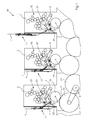
- the FIG. 1 shows a Bogenoffsetrotationsdruckmaschine 30 with multiple printing units in a row construction, of which three printing units 1, 2, 3 are shown.
- Each of the printing units 1, 2, 3 has an inking unit 25, which transfers the ink to a spanned in printing operation on a plate cylinder 23 printing plate with the printed image.
- the printed image is transferred via a blanket cylinder 22 to a substrate 31, which is printed in the nip between blanket cylinder 22 and impression cylinder 26.
- the printing materials 31 are moved by means of transport cylinders 24.
- the impression cylinder 26 and transport cylinder 24 and the blanket cylinder 22 are mechanically connected to each other via a gear train and are driven by a main drive motor 5.
- the plate cylinder 23 in the printing units 1, 2, 3 driven by the here schematically drawn couplings 29 between the plate cylinders 23 and the blanket cylinders 22 are closed. If a print job change is pending, so new plates 6 must be mounted with the new color separations on the plate cylinders 23 and the old printing plates 7 are removed.
- the printing units 1, 2, 3 each have a plate changer 17 on the left side, which accommodates the old printing plate 7 and provides the new printing plate 6.
- the plate cylinders 23 can be disengaged and driven independently of the other cylinders 22, 24, 26 by means of their own drive motor 4 (auxiliary drive).
- FIG. 1 are the three printing units 1, 2, 3 in different positions during the plate change.
- printing unit 3 the plate trailing edge of the old printing plate 7 is just released, so that the old printing plate 7 can be conveyed out.
- printing unit 2 the old printing plate 7 was pushed by the backward plate cylinder 23 out in the disc changer 17.
- the old printing plate 7 has been completely pushed out of the printing unit 1 and in the disc changer 17 in a position in which the new plate can be clamped.
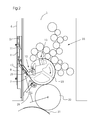
- FIG. 2 is fragmentary, the printing unit 3 shown.
- the plate changer 17 has a lower plate guide element 8 and an upper plate guide element 9.
- a pivotable guide element 10 which is intended to remove the old pressure plate 7 via rollers from the plate cylinder 23.
- the plate changer 17 itself is mechanically stored so that it can be easily lifted and lowered again by the operating personnel by gas pressure springs or other aids.
- the disc changer 17 also carries a sensor 27, with the correct removal of the old plate 7 can be determined.
- On the outside of the disk changer 17 are guide elements with rollers in which the new pressure plate 6 is mounted receptive.
- the guide element 10 is pivoted toward the plate cylinder 23, so that the old pressure plate 7 on the rollers of the guide element 10 out can slide.
- the plate clamping device is opened at the trailing edge 12 on the plate cylinder 23, so that the old pressure plate 7 solves due to their rigidity from the plate cylinder 23 and can slide on the rollers of the pivotable guide element 10 out.
- the feeding out of the old pressure plate 7 is usually done when employed on the plate cylinder 23 blanket cylinder 22, so that the old pressure plate 7 is conveyed in the gap between the blanket cylinder 22 and plate cylinder 23 in the direction of the pivotable guide element 10.
- On the pivotable guide element 10, a further sensor 28 is mounted on the pivotable guide element 10.
- the machine control is informed whether the old pressure plate 7 has actually detached from the plate cylinder 23 and is not tilted for any reason.
- blanket cylinder 22 and plate cylinder 23 are mechanically coupled together and are driven by the continuous gear train on the main drive motor 5.
- the plate cylinder 23 moves in the direction of arrow, so that the old printing plate 7 is required in the disc changer 17.
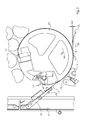
- FIG. 3 shows an enlargement of the area around the plate cylinder 23 in the printing unit 3.
- FIG. 3 is to recognize the open plate clamping device 12 for the plate trailing edge, which allows the feeding out of the old printing plate 7.
- the plate clamping device 13 for the front edge on the plate cylinder 23 remains closed until the old pressure plate 7 has passed the gap between blanket cylinder 22 and plate cylinder 23.
- a pressing element 16 can be seen, which is later required when clamping the new printing plate 6.
- the old pressure plate 7 has been conveyed out of the plate cylinder 23, so that only the plate clamping device for the front edge 13 has to be opened.
- This end position of the pushed out old pressure plate 7 can also be detected by the sensor 27.
- the control computer opens the mechanical clutch 29 between plate cylinder 23 and blanket cylinder 22 and disconnects the two cylinders from each other.
- the clutch 29 can be opened already when the clamping device 12 the Blanket cylinder 22 has happened.
- the plate cylinder 23 is driven only via its associated separate drive motor 4.
- the plate cylinder 23 is then driven independently of the other cylinders 22, 24, 26 in the gear train.
- This plate clamping device 11 is designed so that the old pressure plate 7 can be pushed only in one direction upwards, so that the old pressure plate 7 can not slip back again. This reliably prevents unintentional slipping back in the direction of the plate cylinder 23.
- This plate clamping device 11 consists of a pinch roller 11.1, a clamping surface 11.2 and a guide track 11.3.
- the pinch roller 11.1 When feeding out the old pressure plate 7, the pinch roller 11.1 is pushed along the guideway 11.3 upwards. By its own weight or additional support in the form of a spring force, the roller 11.3 clamps the old pressure plate 7 relative to the clamping surface 11.2, so that slipping back is reliably prevented. As a result, the old pressure plate 7 can only move upwards.
- the control of the printing press changes to a mode for rectifying this fault and, once, stops the main drive 5 of the machine.
- the faulty printing unit 3 goes to "pressure from”, ie the blanket cylinder 22 is turned off by the plate cylinder 23, ie shifted by not shown pneumatic actuated eccentric by ⁇ Z of about 0.5 millimeters in the dot-dash line position ( Fig. 3 ).
- the coupling 29 opens and thus interrupts the power flow between the plate cylinder 23 and the main drive 5 in the printing unit third
- the fault may be, for example, that the clamping rail of the plate clamping device 12 has not opened for the trailing edge of the pressure plate 7, which detected by the sensor 28 and reported by a corresponding signal of the control of the machine.
- the plate cylinder 23 is moved by the drive motor 4 of its auxiliary drive in the position in which the screws of the clamping rail can be opened manually. This is done by the operator and thus suppresses the printing unit.
- the motor 4 of the auxiliary drive rotates the coupled plate cylinder 23 in the currently suppressed printing unit until the end of the plate 7 has reached the sensor 28.
- the positioning movement of the plate cylinder takes place in the forward direction, while the blanket cylinder 22 either stands still or rotates backwards. In this way, it is ensured that the loose trailing edge of the plate 7 can nowhere abut in the printing unit and can thereby bend.
- the main drive 5 rotates in a position in which the printing units 1 and 2 are synchronous to the position occupied by the plate cylinder 23 in the currently suppressed printing unit 3. There, the clutch 29 between plate cylinder 23 and main drive 5 is still open.
- the plate cylinder 23 is now rotated by the drive motor 4 of its auxiliary drive backwards, at the same time the main drive 5 rotates the machine and thus the blanket cylinder 22 in the printing unit 1 also backwards, but with a slightly increased speed.
- the difference ⁇ V between the peripheral speed V PL of the plate cylinder 23 and the peripheral speed V GZ of the blanket cylinder 22 is between 0.5 and 10% of the amount of the speed.
- the plate 7 is then ejected in the printing unit 1 in the disc changer 17 and the drive 4 stops for the currently suppressed printing unit 3 and the operator can remove the ejected plate.
- the operator can create the side mounted on the disc changer 17 new printing plate 6 in all printing on the register pins in the disc clamping device 13 for the leading edge of the plate 6 or the system can be done in an alternative variant by an automatic feed of the plate.
- the new printing plates 6 can be retracted synchronously in all printing units together.
- all the plate cylinder as described above by opening the mechanical clutches 29 separated from the other cylinders 22, 24, 26 in the gear train and also the Beiwolf between the plate cylinders 23 and the blanket cylinders 22 in the non-disturbed printing units 1 and 2 in the position "pressure from "open. If the new pressure plate 6 is correctly applied, the plate clamping device is closed at the leading edge 13 and the control computer triggers the disc tray. In this case, all the plate cylinder 23 rotate in the printing units 1, 2 and 3 driven by the motor 4 of their auxiliary drives slowly forward, because the new printing plates 6 on the "ironing" rollers 15 are pressed to their respective plate cylinder 23.
- the trailing edge of the printing plates is pushed by means of the pressing member 16 in the plate clamping device for the trailing edge 12 so that the plate clamping device 12 can close and the plate is securely locked at the trailing edge.
- the engagement of the plate cylinder 23 in the mechanical gear train is then made automatically by the control computer of the printing press 30. So then the plate changing process is done.
- the undisturbed printing units 1 and 2 terminate their ejection of the old printing plate 7 in such a way that disengages the plate cylinder in the faulty printing unit, and the other printing their ejection in the coupled state only continue when the disturbance in faulty printing unit is manually removed.
- other processes are possible. So it may be useful if, when a fault occurs, for. B. again in the printing unit 3, once all printing units are turned off and go to "pressure off" and are separated via the couplings 29 from the main drive 5 and the gear train of the machine. Then all non-faulty printing units, z. B. continue their ejection by the plate cylinder 23 are moved backwards by the motors 4 of their auxiliary drives.
- the machine also rotates the blanket cylinders 22 backwards, again at a slightly higher peripheral speed, to avoid bulging of the pressure plates 7 as described above in accidental contact with the blanket cylinder. Only then, when all the printing plates are inserted into the non-disturbed printing units 1 and 2 in the respective disc changer 17, stop both the main drive 5 and the motors 4 of the auxiliary drives and the faulty printing unit 3 is then manually suppressed by the operator and can, after its pressure plate is removed, make the plate feeder synchronized with the other non-disturbed printing units.
- the plate cylinder 23 rotates backwards with entklemmter trailing edge, at the same time the blanket cylinder 22 is rotated at a slightly higher peripheral speed also backwards.
Landscapes
- Engineering & Computer Science (AREA)
- Mechanical Engineering (AREA)
- Inking, Control Or Cleaning Of Printing Machines (AREA)
- Supply, Installation And Extraction Of Printed Sheets Or Plates (AREA)
Abstract
Description
Die vorliegende Erfindung betrifft ein Verfahren zum Wechseln von Druckplatten in Rotationsdruckmaschinen mit mehreren Druckwerken. Hierbei kann es sich um Bogen-oder Rollenrotationsmaschinen handeln.The present invention relates to a method for changing printing plates in rotary printing machines with multiple printing units. These may be sheet or web presses.
Es sind bereits eine ganze Reihe unterschiedlicher voll- und halbautomatischer Verfahren bekannt, nach denen die Druckplatten von Offsetdruckmaschinen gewechselt werden. Bei Druckmaschinen, in denen sowohl die Plattenzylinder als auch die Gummituchzylinder der Druckwerke immer getriebemäßig mit dem Hauptantrieb der Druckmaschine verbunden sind, werden die Platten nach dem Öffnen der Spannschienen wegen den unterschiedlichen Phasenlagen der Plattenzylinder relativ zum Maschinenwinkel in den einzelnen Druckwerken sukzessive nacheinander aus dem Druckwerk herausgefördert, nach dem Herausfördern entnommen und die neuen Platten wieder sukzessive in die Druckwerke hineingefördert. In den letzten Jahren sind allerdings auch Druckmaschinen bekannt geworden, bei denen die Plattenzylinder eigene Antriebe besitzen, von denen sie unabhängig vom Maschinenantrieb und damit auch relativ zum Gummituchzylinder verdreht werden können, gegebenenfalls bei Umrüst- bzw. Einrichtvorgängen an der Maschinen, nachdem der jeweilige Plattenzylinder durch eine Kupplung vom Hauptantrieb der Maschine abgekuppelt wurde. Eine solche Druckmaschine ist beispielsweise in der
Nun können im Zuge eines Plattenwechselvorganges Störungen dadurch auftreten, dass sich beispielsweise die Druckplatte in einem Druckwerk beim Herausfördern verkantet, die elektromechanisch betätigte Spannleiste nicht öffnet, die Sensoren zur Erkennung der Plattenkante bzw. des Plattenendes Fehler melden etc. Deshalb wurden bereits auch Betriebsmodi entwickelt, um den Plattenwechselvorgang bei einer solchen Störung möglichst zeiteffektiv abzuschließen. Hierzu schlägt die
Wie man leicht einsieht ist der Gesamtzeitbedarf bei diesem Verfahren nicht minimal, da der Plattenwechsel für das gestörte Druckwerk separat durchgeführt wird und auch nicht teilweise mit dem Wechselvorgang für die übrigen ungestörten Druckwerke zusammenfällt. Es ist allerdings z. B. aus der
Probleme treten auch dann auf, wenn der ausgekuppelte Plattenzylinder mit der darauf befindlichen Platte zum Zwecke des Herausförderns aus dem Druckwerk rückwärts gedreht wird, während der z. B. getriebemäßig mit dem Hauptantrieb der Maschine gekoppelte Plattenzylinder still steht oder eine entgegengesetzte Bewegung ausführt. Denn wenn die aus der Spannleiste gelöste Platte beim Herausfördern aufgrund des geringen Abstands zum Gummituchzylinder mit diesem in Kontakt gerät, kann sich die Platte verbiegen und dann mit mehr oder weniger Wahrscheinlichkeit, abhängig von den räumlichen Verhältnissen im Druckwerk, dem Vorhandensein spezieller Führungen etc. den Weg zurück in die Entnahmeposition am Schutz des Druckwerks verfehlen, dabei womöglich geknickt werden etc. Es ist deshalb die Aufgabe der vorliegenden Erfindung, bei einem Plattenwechselverfahren der eingangs genannten Art diese so zu gestalten, dass die Platten in den Betriebsarten, bei denen das Herausfördern der Platten aus dem Druckwerk durch den separat angetriebenen, ausgekuppelten Plattenzylinder erfolgt, also beispielsweise bei einer Störung, möglichst sicher vonstatten geht. Diese Aufgabe wird mit den im Anspruch 1 angegebenen Merkmalen gelöst.Problems also occur when the disengaged plate cylinder with the plate thereon for the purpose of conveying out of the printing unit backwards is rotated while the z. B. geared to the main drive of the machine coupled plate cylinder stands still or performs an opposite movement. Because if the disc released from the clamping plate when conveying out due to the small distance to the blanket cylinder with this in contact, the plate may bend and then with more or less probability, depending on the spatial conditions in the printing unit, the presence of special guides, etc. the It is therefore the object of the present invention, in a plate changing method of the type mentioned above to make them so that the plates in the operating modes in which the conveying out of the Plates from the printing unit by the separately driven, disengaged plate cylinder takes place, so for example in case of failure, as safe as possible. This object is achieved with the features specified in claim 1.
Gemäß der Erfindung wird beim Herausfördern einer oder mehrerer Druckplatten durch den ausgekuppelten Plattenzylinder der jeweilige Gummituchzylinder mit einer etwas höheren Umfangsgeschwindigkeit als der zugehörige Plattenzylinder bewegt. Das hat zur Folge, dass die Druckplatte, wenn sie denn während der Auswurfbewegung mit dem Gummituchzylinder in Berührung kommt, nicht gestaucht wird, sondern durch die etwas höhere Umfangsgeschwindigkeit des Gummituches allenfalls "gerade gezogen" wird. Auf diese Weise findet sie stets sicher ihren Weg zurück in die Halteposition am Schutz des Druckwerkes. Wenn nun also beispielsweise im Modus zum Abarbeiten einer Störung der Plattenzylinder im gestörten Druckwerk die Platte nach dem Beseitigen der Störung aus dem Druckwerk heraus befördert, nachdem der Plattenwechsel für die nicht gestörten Druckwerke bereits komplett abgeschlossen ist und keine Notwendigkeit bestünde, den Maschinenantrieb mit allen davon angetriebenen Gummituchzylindern zu bewegen, würde man zweckmäßig nach dem erfindungsgemäßen Verfahren dennoch gleichzeitig den Maschinenantrieb einschalten, um die Gummituchzylinder mit einer geringfügig höheren Umfangsgeschwindigkeit tangential in die gleiche Richtung drehen lassen, in die die Platte abgefördert wird. Die gleiche Maßnahme kann zweckmäßig natürlich auch getroffen werden, wenn vor oder nach dem Beseitigen der Störung die Plattenzylinder die Druckplatten in den nicht oder nicht mehr gestörten Druckwerken herausbewegen sowie bei Plattenwechselverfahren, bei denen das Herausbefördern immer durch den Plattenzylinder im abgestellten und vom Hauptantrieb der Maschine abgekuppelten Zustand erfolgt.According to the invention, when one or more printing plates are fed out through the disengaged plate cylinder, the respective blanket cylinder is moved at a slightly higher peripheral speed than the associated plate cylinder. This has the consequence that the pressure plate, if it comes during the ejection movement with the blanket cylinder in contact, is not compressed, but at best "pulled straight" by the slightly higher peripheral speed of the blanket. In this way, she always safely finds her way back to the holding position on the protection of the printing unit. So now if, for example, in the mode for processing a fault, the plate cylinder in the faulty printing unit, the plate after eliminating the disturbance from the printing unit out after the plate change for the undisturbed printing units is already complete and there is no need, the machine drive with all of them To move driven blanket cylinders, you would expediently turn on the machine drive according to the method of the invention at the same time to allow the blanket cylinder rotate tangentially in the same direction with a slightly higher peripheral speed, in which the plate is conveyed away. Of course, the same measure can also be taken if, before or after the elimination of the disturbance, the plate cylinders move the printing plates out of the no or no longer disturbed printing units, as well in plate change processes in which the removal is always carried out by the plate cylinder in the parked and uncoupled from the main drive of the machine state.
Besonders schnell ist das erfindungsgemäße Verfahren zum Wechseln von Druckplatten auch im Störungsfalle, wenn wie in Anspruch 4 vorgesehen beim Auftreten einer Störung in einem Druckwerk die Plattenzylinder in den nicht gestörten Druckwerken ausgekuppelt werden, wobei die jeweiligen Gummituchzylinder in diesen Druckwerken mit einer etwas höheren Geschwindigkeit als die Plattenzylinder bewegt werden, während diese den Auswurfvorgang fortsetzen und gleichzeitig wie in Anspruch 6 beschrieben auch der Plattenzylinder des gestörten Druckwerks ausgekuppelt wird und dort der Plattenzylinder in die Position gefahren wird, in der die Störung beseitigt werden kann, beispielsweise die Position, in der die Schrauben der Plattenspannschiene manuell geöffnet werden können, oder der Plattenzylinder des gestörten Druckwerks in eine Referenzposition fährt. Generell ist es vorteilhaft, wenn die Störung beseitigt wird, bevor in den nicht gestörten Druckwerken neue Druckplatten eingespannt werden. In dem Falle können nämlich nach dem Auswurf der Platte in dem gestörten Druckwerk in allen Druckwerken der Maschine die Platten zeitgleich und synchron eingezogen werden. Weitere Vorteile der Erfindung ergeben sich aus der nachfolgenden Beschreibung von Ausführungsbeispielen anhand der
Die
In
Die Abbildung in
In
Liegt jedoch in einem Druckwerk, beispielsweise im Druckwerk 3, eine Störung vor, dann wechselt die Steuerung der Druckmaschine in einen Modus zur Behebung dieser Störung und setzt erst einmal den Hauptantrieb 5 der Maschine still. Anschließend geht das störungsbehaftete Druckwerk 3 auf "Druck ab", d. h. der Gummituchzylinder 22 wird vom Plattenzylinder 23 abgestellt, d. h. über nicht dargestellte pneumatisch betätigte Exzenter um ΔZ von ca. 0,5 Millimeter in die strichpunktiert gezeichnete Stellung verschoben (
Die Störung kann beispielsweise darin liegen, dass die Spannschiene der Plattenklemmeinrichtung 12 für die Hinterkante der Druckplatte 7 nicht geöffnet hat, was von dem Sensor 28 erkannt und durch ein entsprechendes Signal der Steuerung der Maschine gemeldet wurde. In diesem Falle wird der Plattenzylinder 23 von dem Antriebsmotor 4 seines Hilfsantriebs in die Position gefahren, in der die Schrauben der Spannschiene manuell geöffnet werden können. Dies wird von der Bedienperson erledigt und somit das Druckwerk entstört.The fault may be, for example, that the clamping rail of the
Anschließend drückt der Bediener die Taste für das Weiterlaufen des Antriebs und die nichtstörungsbehafteten Druckwerke, z. B. 2 und 3, setzen den Auswurf der alten Druckplatte 7 wie im vorhergehenden beschrieben fort. Während dessen dreht der Motor 4 des Hilfsantriebs den angekuppelten Plattenzylinder 23 im gerade entstörten Druckwerk bis das Ende der Platte 7 den Sensor 28 erreicht hat.Subsequently, the operator presses the button for the continued operation of the drive and the non-malfunctioning printing units, for. B. 2 and 3, continue the ejection of the
Die Positionierbewegung des Plattenzylinders erfolgt in Vorwärtsrichtung, während der Gummituchzylinder 22 entweder still steht oder rückwärts dreht. Auf diese Weise ist sichergestellt, dass die lose Hinterkante der Platte 7 im Druckwerk nirgends anstoßen kann und sich dabei verbiegen kann. Nachdem nun die Platten in den nicht gestörten Druckwerken 2 und 3 ausgespannt sind, dreht der Hauptantrieb 5 in eine Position, in der die Druckwerke 1 und 2 synchron zur Position sind, die der Plattenzylinder 23 im gerade entstörten Druckwerk 3 einnimmt. Dort ist die Kupplung 29 zwischen Plattenzylinder 23 und Hauptantrieb 5 nach wie vor offen. Um jetzt die Platte 7 im Druckwerk 1 auszuwerfen, wird der Plattenzylinder 23 nunmehr von dem Antriebsmotor 4 seines Hilfsantriebes rückwärts gedreht, gleichzeitig dreht der Hauptantrieb 5 die Maschine und damit auch den Gummituchzylinder 22 im Druckwerk 1 ebenfalls rückwärts, jedoch mit einer etwas erhöhten Geschwindigkeit. Die Differenz δV zwischen der Umfangsgeschwindigkeit VPL des Plattenzylinders 23 und der Umfangsgeschwindigkeit VGZ des Gummituchzylinders 22 liegt zwischen 0,5 und 10 % des Betrages der Geschwindigkeit. Auf diese Weise ist sichergestellt, dass sich die Druckplatte 7, deren Hinterkante ja gelöst ist, nicht durch einen zufälligen Kontakt mit der Oberfläche des Gummituchs auf dem Gummituchzylinder 22 ausbaucht oder verbiegt, denn die etwas höhere Umfangsgeschwindigkeit des Gummituchzylinders 22 übt in dem Falle einen Zug auf die Platte 7 aus, die ja durch die Spannschiene 13 mit ihrer Vorderkante noch eingespannt ist.The positioning movement of the plate cylinder takes place in the forward direction, while the
Wenn die Platte 7 im Druckwerk 1 dann in den Plattenwechsler 17 ausgeschoben ist stoppt auch der Antrieb 4 für das gerade entstörte Druckwerk 3 und der Bediener kann die ausgeschobene Platte entfernen. Nun kann das Bedienpersonal die seitlich am Plattenwechsler 17 angebrachte neue Druckplatte 6 in allen Druckwerken an die Registerstifte in der Plattenklemmeinrichtung 13 für die Vorderkante der Platte 6 anlegen oder die Anlage kann in einer alternativen Variante durch eine automatische Zuführung der Platte erfolgen.When the
Anschließend können in allen Druckwerken gemeinsam jeweils die neuen Druckplatten 6 synchron eingezogen werden. Hierzu werden alle Plattenzylinder wie vorstehend beschrieben durch Öffnen der mechanischen Kupplungen 29 von den anderen Zylindern 22, 24, 26 im Zahnräderzug abgetrennt und auch die Beistellung zwischen den Plattenzylindern 23 und den Gummituchzylindern 22 in den nicht gestörten Druckwerken 1 und 2 in die Stellung "Druck ab" geöffnet. Wenn die neue Druckplatte 6 jeweils korrekt anliegt, wird die Plattenklemmeinrichtung an der Vorderkante 13 geschlossen und der Steuerungsrechner löst den Platteneinzug aus. Dabei drehen jetzt alle Plattenzylinder 23 in den Druckwerken 1, 2 und 3 angetrieben vom Motor 4 ihrer Hilfsantriebe langsam vorwärts, weil die neuen Druckplatten 6 über die "Aufbügel"walzen 15 an ihren jeweiligen Plattenzylinder 23 gedrückt werden. Nach komplettem Einzug der neuen Druckplatten 6 wird die Hinterkante der Druckplatten mittels des Andrückelements 16 in die Plattenklemmeinrichtung für die Hinterkante 12 geschoben, so dass die Plattenklemmeinrichtung 12 schließen kann und die Platte jeweils sicher an der Hinterkante verriegelt ist. Das Einkuppeln der Plattenzylinder 23 in den mechanischen Räderzug wird dann vom Steuerungsrechner der Druckmaschine 30 automatisch vorgenommen. Damit ist dann der Plattenwechselvorgang erledigt.Subsequently, the
Im vorliegenden Ausführungsbeispiel wurde beschrieben, dass die nicht gestörten Druckwerke 1 und 2 erst ihren Auswurf der alten Druckplatte 7 in der Weise beenden, dass der Plattenzylinder im gestörten Druckwerk auskuppelt, und die anderen Druckwerke ihren Auswurf im eingekoppelten Zustand erst fortsetzen, wenn die Störung im gestörten Druckwerk manuell beseitigt ist. Hier sind jedoch auch andere Abläufe möglich. So kann es zweckmäßig sein, wenn beim Auftreten einer Störung, z. B. auch wieder im Druckwerk 3, erst einmal alle Druckwerke abgestellt werden und auf "Druck ab" gehen und über die Kupplungen 29 vom Hauptantrieb 5 bzw. dem Räderzug der Maschine getrennt werden. Sodann können alle nicht störungsbehafteten Druckwerke, z. B. ihren Auswurf fortsetzen, indem die Plattenzylinder 23 durch die Motoren 4 ihrer Hilfsantriebe rückwärts bewegt werden. Währenddessen dreht die Maschine die Gummituchzylinder 22 ebenfalls rückwärts und zwar auch wieder mit einer etwas höheren Umfangsgeschwindigkeit, um ein Ausbauchen der Druckplatten 7 wie vorstehend beschrieben bei zufälligem Kontakt mit dem Gummituchzylinder zu vermeiden. Erst dann, wenn so alle Druckplatten in den nicht gestörten Druckwerken 1 und 2 in die jeweiligen Plattenwechsler 17 eingeschoben sind, stoppen sowohl der Hauptantrieb 5 als auch die Motoren 4 der Hilfsantriebe und das gestörte Druckwerk 3 wird anschließend von der Bedienperson manuell entstört und kann, nachdem seine Druckplatte entfernt ist, den Platteneinzug synchron mit den anderen nicht gestörten Druckwerken vornehmen.In the present embodiment, it was described that the
Als weitere Alternative ist es auch möglich, in den nicht gestörten Druckwerken den Plattenwechselvorgang komplett mit dem Einzug der neuen Platten vorzunehmen, bevor die manuelle Entstörung in dem gestörten Druckwerk erfolgt.As a further alternative, it is also possible to carry out the plate changing operation in the undisturbed printing units completely with the insertion of the new plates, before the manual suppression in the faulty printing unit.
In allen Fällen aber wird dann, wenn in einem Druckwerk der Plattenzylinder 23 bei entklemmter Hinterkante rückwärts dreht, gleichzeitig der Gummituchzylinder 22 mit etwas erhöhter Umfangsgeschwindigkeit ebenfalls rückwärts gedreht.In all cases, however, when in a printing unit, the
- 11
- erstes Druckwerkfirst printing unit
- 22
- zweites Druckwerksecond printing unit
- 33
- drittes Druckwerkthird printing unit
- 44
- Antriebsmotoren (Hilfsantrieb)Drive motors (auxiliary drive)
- 55
- HauptantriebsmotorMain drive motor
- 66
- neue Druckplattenew printing plate
- 77
- alte Druckplatteold printing plate
- 88th
- unteres Plattenführungselementlower plate guide element
- 99
- oberes Plattenführungselementupper plate guide element
- 1010
- schwenkbares Leitelementswiveling guide element
- 1111
- PlattenklemmeinrichtungDisc clamper
- 11.111.1
- Klemmrollepinch roller
- 11.211.2
- Klemmflächeclamping surface
- 11.311.3
- Führungsbahnguideway
- 1212
- Plattenklemmeinrichtung HinterkantePlate clamping device trailing edge
- 1313
- Plattenklemmeinrichtung VorderkantePlate clamping device leading edge
- 1414
- Schutzeinrichtungguard
- 1515
- AufbügelwalzeAufbügelwalze
- 1616
- Andrückelementpressing element
- 1717
- Plattenwechslerrecord changer
- 2222
- GummituchzylinderBlanket cylinder
- 2323
- Plattenzylinderplate cylinder
- 2424
- Transportzylindertransport cylinder
- 2525
- Farbwerkinking
- 2626
- GegendruckzylinderImpression cylinder
- 2727
- Sensorsensor
- 2828
- Plattensensor HinterkantePlate sensor trailing edge
- 2929
- Kupplungclutch
- 3030
- Druckmaschinepress
- 3131
- Bogenbow
Claims (12)
dadurch gekennzeichnet,
dass während des Plattenwechselvorgangs zumindest in einer Betriebsart beim Herausfördern einer oder mehrerer Druckplatten (7) aus dem Druckwerk (3) der jeweilige Gummituchzylinder (22) mit einer etwas höheren Umfangsgeschwindigkeit (VGZ) als der zugehörige Plattenzylinder (23) bewegt wird.Method for changing printing plates (6, 7) in rotary printing machines having a plurality of printing units, in which the plate cylinders (23) have their own drive (4) via which they are independent of the associated blanket cylinder (22) in the respective printing unit (1, 2, 3) are drivable,
characterized,
in that, during the plate changing operation, the respective blanket cylinder (22) is moved at a slightly higher peripheral speed (V GZ) than the associated plate cylinder (23) when one or more printing plates (7) are fed out of the printing unit (3).
wobei es sich bei der Betriebsart um den Modus zum Abarbeiten einer Störung handelt und zumindest der Gummituchzylinder (22) des Druckwerks (3), in dem die Störung vorliegt oder vorgelegen hat, mit der höheren Umfangsgeschwindigkeit (VGZ) gedreht wird.Method according to claim 1,
wherein the mode is the mode for dealing with a disturbance and at least the blanket cylinder (22) of the printing unit (3) in which the disturbance exists or has been present is rotated at the higher peripheral speed (V GZ ).
wobei es sich bei der Betriebsart um den Modus zum Abarbeiten einer Störung handelt und mehrere mechanisch miteinander gekoppelte Gummituchzylinder (22) gleichzeitig mit einer etwas höheren Umfangsgeschwindigkeit (VGZ) als die zugehörigen Plattenzylinder (23) bewegt werden.Method according to claim 1,
wherein the mode is the mode for dealing with a disturbance and a plurality of mechanically coupled blanket cylinders (22) are simultaneously moved at a slightly higher peripheral speed (V GZ ) than the associated plate cylinders (23).
wobei es sich bei der Betriebsart um eine Störung handelt und nach dem Auftreten der Störung das Herausfördern der Platten in den nicht gestörten Druckwerken (1, 2) fortgesetzt wird, wobei die jeweiligen Gummituchzylinder (22) dieser Druckwerke mit der etwas höheren Geschwindigkeit (VGZ) bewegt werden als die zugehörigen Plattenzylinder (23), anschließend die Störung in dem gestörten Druckwerk (3) beseitigt und dort die Platte (7) herausgefördert wird, und anschließend der Platteneinzug für alle Druckwerke (1, 2, 3) synchron vorgenommen wird bzw. gleichzeitig erfolgt.Method according to one of claims 1 to 3,
wherein the mode is a disorder and after the occurrence of the disturbance, the feeding out of the plates in the non-disturbed printing units (1, 2) is continued, wherein the respective blanket cylinder (22) of these printing units with the slightly higher speed (V GZ ) are moved as the associated plate cylinder (23), then eliminates the disturbance in the disturbed printing unit (3) and there the plate (7) is conveyed out, and then the plate feeder for all printing units (1, 2, 3) is made synchronous or at the same time.
wobei es sich bei der Betriebsart um eine Störung handelt und nach dem Auftreten der Störung erst einmal der Plattenwechselvorgang in den nicht gestörten Druckwerken komplett abgeschlossen wird, wobei dort neue Druckplatten (6) in die Druckwerke (1, 2) gefordert und auf den Plattenzylindern (23) befestigt werden, und anschließend die Störung in dem gestörten Druckwerk (23) beseitigt wird, wobei im Zuge des Herausförderns der Druckplatte (7) in dem gestörten Druckwerk (3) der Gummituchzylinder (22) mit etwas höherer Geschwindigkeit (VGZ) bewegt wird als der Plattenzylinder (23).Method according to one of claims 1 to 3,
wherein it is a fault in the mode and after the occurrence of the disturbance once the plate change process in the non-disturbed printing units is completely completed, where there new printing plates (6) in the printing units (1, 2) required and on the plate cylinders ( 23) are fixed, and then the disturbance in the faulty printing unit (23) is eliminated, wherein in the course of feeding out the pressure plate (7) in the disturbed printing unit (3) of the blanket cylinder (22) moves at a slightly higher speed (V GZ ) is called the plate cylinder (23).
wobei im Zuge des Abarbeitens der Störung der Plattenzylinder (23) des gestörten Druckwerks (3) ausgekuppelt wird und in die Position gefahren wird, in der die Befestigungsmittel (12) zugänglich sind, mit der die Platte (7) auf dem Zylinder (23) gespannt ist, und anschließend die Befestigungsmittel (12) manuell gelöst werden.Method according to one of claims 2 to 5,
wherein in the course of the completion of the fault, the plate cylinder (23) of the defective printing unit (3) is disengaged and moved to the position in which the fastening means (12) are accessible, with which the plate (7) on the cylinder (23) is tensioned, and then the fastening means (12) are released manually.
wobei im Zuge des Abarbeitens der Störung der Plattenzylinder (23) des gestörten Druckwerks ausgekuppelt wird und in eine Referenzposition gedreht wird, während gleichzeitig die Platten in den nicht gestörten Druckwerken (1,2) herausgefördert werden und danach bei weiterhin ausgekuppeltem Plattenzylinder (23) im gestörten Druckwerk die Plattenzylinder (23) der anderen Druckwerke (1, 2) in eine Position gedreht werden, die mit der Referenzposition des Plattenzylinders (23) im gestörten Druckwerk (3) synchronisiert ist.Method according to one of claims 2 to 6,
wherein in the course of the completion of the disturbance of the plate cylinder (23) of the defective printing unit is disengaged and is rotated to a reference position, while the plates in the undisturbed printing units (1,2) are conveyed out and then with still disengaged plate cylinder (23) in Disturbed printing unit, the plate cylinder (23) of the other printing units (1, 2) are rotated to a position which is synchronized with the reference position of the plate cylinder (23) in the disturbed printing unit (3).
wobei anschließend die Druckplatte (7) im gestörten Druckwerk (3) herausgefördert wird, während gleichzeitig die mit dem Maschinenantrieb (15) verbundenen Gummituchzylinder (22) aller Druckwerke (1, 2, 3) mit etwas höherer Umfangsgeschwindigkeit (VGZ) rückwärts gedreht werden.Method according to claim 7,
wherein subsequently the pressure plate (7) in the disturbed printing unit (3) is conveyed out, while at the same time with the machine drive (15) connected blanket cylinder (22) of all printing units (1, 2, 3) with a slightly higher peripheral speed (V GZ ) are rotated backwards ,
wobei nach dem Herausfördern der Druckplatten (23) in den nicht gestörten Druckwerken (1,2), dem Beseitigen der Störung im gestörten Druckwerk (3) und dem Herausfördern der Platte (7) aus dem gestörten Druckwerk (3) in alle Druckwerke neue Platten (6) zugeführt werden, wobei im Zuge des Hineinförderns der neuen Platten (6) die Plattenzylinder (23) aller Druckwerke (1, 2, 3) ausgekuppelt sind und die neuen Platten synchron in die jeweiligen Druckwerke hineinbefördert werden, indem die den Plattenzylindern zugeordneten Hilfsantriebe (4) diese Plattenzylinder (23) alle gleichzeitig drehen (bewegen).Method according to one of claims 6 to 8,
wherein after the conveying out of the printing plates (23) in the undisturbed printing units (1,2), eliminating the disturbance in the disturbed printing unit (3) and the conveying out of the plate (7) from the disturbed printing unit (3) in all printing units new plates (6) are fed, wherein in the course of driving in the new plates (6), the plate cylinder (23) of all printing units (1, 2, 3) are disengaged and the new plates are conveyed synchronously in the respective printing units by the plate cylinders associated Auxiliary drives (4) rotate (move) these plate cylinders (23) all at the same time.
wobei jedes Druckwerk (1-3) einen Plattenzylinder (23) und einen Gummizylinder (22) enthält, der mit dem Maschinenantrieb (5) kuppelbar ist, während der Plattenzylinder (23) einen eigenen Antrieb (4) besitzt, über den er unabhängig vom zugehörigen Gummituchzylinder (22) antreibbar ist, sowie mit einer Steuerung, von der die Antriebe für die Gummituchzylinder und die Plattenzylinder entsprechend unterschiedlicher Betriebsarten bzw. Modi ansteuerbar sind,
dadurch gekennzeichnet,
dass das Steuerprogramm den oder die jeweiligen Gummituchzylinder zumindest in einer Betriebsart mit einer etwas höheren Umfangsgeschwindigkeit (VGZ) als einen zugehörigen Plattenzylinder (23) bewegt.Printing machine with several printing units,
wherein each printing unit (1-3) comprises a plate cylinder (23) and a blanket cylinder (22) which is coupled to the machine drive (5), while the plate cylinder (23) has its own drive (4), over which it independently associated blanket cylinder (22) is drivable, as well as with a control of which the drives for the blanket cylinder and the plate cylinder according to different operating modes or modes can be controlled,
characterized,
in that the control program moves the blanket cylinder (s), at least in an operating mode, at a slightly higher peripheral speed (V GZ ) than an associated plate cylinder (23).
dadurch gekennzeichnet,
dass die Steuerung in der Betriebsart Druckplattenwechsel mindestens beim Eingang einer Fehlermeldung für das Herausfördern einer oder mehrerer Druckplatten (7) aus dem Druckwerk (3) die Antriebe (4 und 5) von Plattenzylinder (23) und Gummituchzylinder (22) in mindestens einem Druckwerk so steuert, dass der Gummituchzylinder (22) mit einer etwas höheren Umfangsgeschwindigkeit (VGZ) als der zugehörige Plattenzylinder (22) dreht.Control for rotary printing machines having a plurality of printing units (1 - 3), in which the plate cylinders (23) have their own drive (4) via which the plate cylinders (23) can be driven independently of the associated blanket cylinder (22) in the printing units,
characterized,
that the control in the printing plate change mode at least upon receipt of an error message for feeding out one or more printing plates (7) from the printing unit (3) the drives (4 and 5) of plate cylinder (23) and blanket cylinder (22) in at least one printing unit so controls that the blanket cylinder (22) rotates at a slightly higher peripheral speed (V GZ ) than the associated plate cylinder (22).
Applications Claiming Priority (1)
| Application Number | Priority Date | Filing Date | Title |
|---|---|---|---|
| DE102010012280A DE102010012280A1 (en) | 2010-03-22 | 2010-03-22 | Method for changing printing plates in rotary presses with multiple printing units |
Publications (2)
| Publication Number | Publication Date |
|---|---|
| EP2368710A1 true EP2368710A1 (en) | 2011-09-28 |
| EP2368710B1 EP2368710B1 (en) | 2014-04-09 |
Family
ID=43836598
Family Applications (1)
| Application Number | Title | Priority Date | Filing Date |
|---|---|---|---|
| EP20110155520 Active EP2368710B1 (en) | 2010-03-22 | 2011-02-23 | Method for changing printing plates in a printing press with multiple printing units |
Country Status (5)
| Country | Link |
|---|---|
| US (1) | US9061487B2 (en) |
| EP (1) | EP2368710B1 (en) |
| JP (1) | JP5904713B2 (en) |
| CN (1) | CN102211449B (en) |
| DE (1) | DE102010012280A1 (en) |
Cited By (1)
| Publication number | Priority date | Publication date | Assignee | Title |
|---|---|---|---|---|
| WO2014101992A1 (en) * | 2012-12-28 | 2014-07-03 | Bobst Lyon | Printing module for printing from negatives onto plate elements, and conversion machine including such a printing module |
Families Citing this family (9)
| Publication number | Priority date | Publication date | Assignee | Title |
|---|---|---|---|---|
| EP2771742B1 (en) * | 2011-10-25 | 2016-05-25 | Hewlett-Packard Indigo B.V. | Replacement system for a image transfer blanket and method thereof |
| JP6116224B2 (en) * | 2012-02-16 | 2017-04-19 | リョービMhiグラフィックテクノロジー株式会社 | Plate cylinder phase switching device for printing press |
| JP5999752B2 (en) * | 2012-02-21 | 2016-09-28 | 株式会社ミヤコシ | Variable printing machine |
| DE102013012708B4 (en) * | 2012-09-10 | 2022-04-21 | Heidelberger Druckmaschinen Intellectual Property Ag & Co. Kg | Register adjustment during set-up processes on printing presses |
| JP2014226859A (en) * | 2013-05-23 | 2014-12-08 | 株式会社秀峰 | Printing method |
| DE102016206225A1 (en) * | 2015-05-22 | 2016-11-24 | Heidelberger Druckmaschinen Ag | Printing machine with a disc changer |
| DE102016207018A1 (en) * | 2015-05-22 | 2016-11-24 | Heidelberger Druckmaschinen Ag | Plate fastening method and printing machine for carrying out |
| DE102017209487A1 (en) * | 2017-06-06 | 2018-12-06 | Koenig & Bauer Ag | Method for operating a sheet-fed printing machine with multiple printing units |
| DE102018220320A1 (en) * | 2018-01-23 | 2019-07-25 | Heidelberger Druckmaschinen Ag | Method for controlling plate clamping in a printing machine |
Citations (6)
| Publication number | Priority date | Publication date | Assignee | Title |
|---|---|---|---|---|
| DE19636703A1 (en) | 1996-09-10 | 1998-03-12 | Roland Man Druckmasch | Device for controlling an automatic printing plate change |
| WO2002024454A1 (en) * | 2000-09-20 | 2002-03-28 | Koenig & Bauer Aktiengesellschaft | Printing unit |
| WO2006018105A2 (en) | 2004-08-13 | 2006-02-23 | Man Roland Druckmaschinen Ag | Method for controlling a machine for processing sheet material |
| DE102008030438A1 (en) | 2007-07-13 | 2009-01-22 | Heidelberger Druckmaschinen Ag | Improved plate change in sheetfed offset presses |
| EP2036726A2 (en) * | 2007-09-15 | 2009-03-18 | manroland AG | Method for operating a sheet fed printing press |
| EP1348551B1 (en) | 2002-03-28 | 2009-05-27 | Komori Corporation | Plate handling method and apparatus for printing press |
Family Cites Families (7)
| Publication number | Priority date | Publication date | Assignee | Title |
|---|---|---|---|---|
| JPS5926265A (en) * | 1982-08-04 | 1984-02-10 | Komori Printing Mach Co Ltd | Safety device for cylinder press machine |
| DE3940796A1 (en) * | 1989-12-09 | 1991-06-13 | Koenig & Bauer Ag | METHOD AND DEVICE FOR AUTOMATICALLY CHANGING A PRINT PLATE |
| DE19640649A1 (en) * | 1996-10-02 | 1998-04-16 | Roland Man Druckmasch | Drive for a sheet printing machine |
| US6125757A (en) * | 1998-10-19 | 2000-10-03 | Heidelberger Druckmaschinen Ag | Method and apparatus for performing a flying printing plate change |
| JP2004508984A (en) * | 2000-09-20 | 2004-03-25 | ケーニツヒ ウント バウエル アクチエンゲゼルシヤフト | Printing unit |
| DE10046370B4 (en) * | 2000-09-20 | 2005-02-03 | Koenig & Bauer Ag | printing unit |
| JP4702916B2 (en) * | 2001-03-05 | 2011-06-15 | 株式会社ミヤコシ | Rotary printing press |
-
2010
- 2010-03-22 DE DE102010012280A patent/DE102010012280A1/en not_active Withdrawn
-
2011
- 2011-02-23 EP EP20110155520 patent/EP2368710B1/en active Active
- 2011-03-18 JP JP2011060187A patent/JP5904713B2/en not_active Expired - Fee Related
- 2011-03-22 CN CN201110071456.3A patent/CN102211449B/en active Active
- 2011-03-22 US US13/053,699 patent/US9061487B2/en not_active Expired - Fee Related
Patent Citations (6)
| Publication number | Priority date | Publication date | Assignee | Title |
|---|---|---|---|---|
| DE19636703A1 (en) | 1996-09-10 | 1998-03-12 | Roland Man Druckmasch | Device for controlling an automatic printing plate change |
| WO2002024454A1 (en) * | 2000-09-20 | 2002-03-28 | Koenig & Bauer Aktiengesellschaft | Printing unit |
| EP1348551B1 (en) | 2002-03-28 | 2009-05-27 | Komori Corporation | Plate handling method and apparatus for printing press |
| WO2006018105A2 (en) | 2004-08-13 | 2006-02-23 | Man Roland Druckmaschinen Ag | Method for controlling a machine for processing sheet material |
| DE102008030438A1 (en) | 2007-07-13 | 2009-01-22 | Heidelberger Druckmaschinen Ag | Improved plate change in sheetfed offset presses |
| EP2036726A2 (en) * | 2007-09-15 | 2009-03-18 | manroland AG | Method for operating a sheet fed printing press |
Cited By (4)
| Publication number | Priority date | Publication date | Assignee | Title |
|---|---|---|---|---|
| WO2014101992A1 (en) * | 2012-12-28 | 2014-07-03 | Bobst Lyon | Printing module for printing from negatives onto plate elements, and conversion machine including such a printing module |
| FR3000429A1 (en) * | 2012-12-28 | 2014-07-04 | Bobst Lyon | PRINTING MODULE FOR PRINTING FROM SHEETS ON PLATE ELEMENTS AND PROCESSING MACHINE COMPRISING SUCH A PRINTING MODULE |
| CN104903109A (en) * | 2012-12-28 | 2015-09-09 | 鲍勃斯脱里昂公司 | Printing module for printing from negatives onto plate elements, and conversion machine including such a printing module |
| US9975325B2 (en) | 2012-12-28 | 2018-05-22 | Bobst Lyon | Printing unit for printing plate elements from printing plates and converting machine comprising such a printing unit |
Also Published As
| Publication number | Publication date |
|---|---|
| CN102211449A (en) | 2011-10-12 |
| CN102211449B (en) | 2015-03-11 |
| EP2368710B1 (en) | 2014-04-09 |
| JP2011194892A (en) | 2011-10-06 |
| DE102010012280A1 (en) | 2011-09-22 |
| JP5904713B2 (en) | 2016-04-20 |
| US9061487B2 (en) | 2015-06-23 |
| US20110226146A1 (en) | 2011-09-22 |
Similar Documents
| Publication | Publication Date | Title |
|---|---|---|
| EP2368710B1 (en) | Method for changing printing plates in a printing press with multiple printing units | |
| DE102008030438B4 (en) | Improved plate change in sheetfed offset presses | |
| EP0933206B1 (en) | Methods and devices for automatically feeding and/or removing printing plates to/from a plate cylinder of a printing machine | |
| DE69619901T2 (en) | Automatic paper feeder | |
| DE69331898T2 (en) | Sheet conveying apparatus | |
| DE102012014806A1 (en) | Method for exchanging printing plate in plate cylinder of printing machine, involves opening clamping device for leading edge of printing plate, and removing printing plate by rollers without stopping reverse rotation of plate cylinder | |
| DE3876362T2 (en) | APPARATUS FOR PAPER TRANSPORT IN A PRINTER. | |
| DE4439623C2 (en) | Process for the automatic feeding of printing plates | |
| DE69006481T2 (en) | Printing machine with movable inking unit. | |
| DE102007040694A1 (en) | Method for changing over operating procedure e.g. for letter quality printing, involves holding control roller in position spaced away from control cam | |
| DE69303916T2 (en) | Device for changing printing plates in a printing machine | |
| DE102016000358A1 (en) | Cylinder lifting / lowering device for a printing machine | |
| EP1070583B1 (en) | Method and device for the printing plate change. | |
| DE102008005797A1 (en) | Extension arm for sheet-processing machine, particularly sheet-fed printing machine, has rotary leading edge gripper system that carries sheets on leading edge from sheet guide cylinder, mounted upstream to leading edge gripper system | |
| DE3316580C1 (en) | Device for monitoring the correct paper inlet in typewriters and similar machines | |
| DE102004006942A1 (en) | Method for automatic print master changing in offset printing press has the master roller clutch disengaged and the roller driven by a variable speed drive roller | |
| DE102008005798A1 (en) | Printer has device for transporting pressure plates, where printer has multiple printing units, where printing units are arranged in printer extending along plate transport system | |
| DE102013202317B4 (en) | Method and device for switching a plate cylinder phase of a printing machine | |
| DE102014210109A1 (en) | Method for uninterrupted stack change on a sheet-processing machine and delivery | |
| EP2036726B1 (en) | Method for operating a sheet fed printing press | |
| DE69417352T3 (en) | Pressure switching device for a sheet-fed printing machine with a turning device | |
| EP2050568A2 (en) | Method and device for exchanging a printing plate on a processing machine | |
| DE310813C (en) | ||
| DE10222002B4 (en) | Method and device for changing printing plates | |
| DE10054512B4 (en) | Phase difference detecting means in a printing press |
Legal Events
| Date | Code | Title | Description |
|---|---|---|---|
| PUAI | Public reference made under article 153(3) epc to a published international application that has entered the european phase |
Free format text: ORIGINAL CODE: 0009012 |
|
| AK | Designated contracting states |
Kind code of ref document: A1 Designated state(s): AL AT BE BG CH CY CZ DE DK EE ES FI FR GB GR HR HU IE IS IT LI LT LU LV MC MK MT NL NO PL PT RO RS SE SI SK SM TR |
|
| AX | Request for extension of the european patent |
Extension state: BA ME |
|
| 17P | Request for examination filed |
Effective date: 20120328 |
|
| GRAP | Despatch of communication of intention to grant a patent |
Free format text: ORIGINAL CODE: EPIDOSNIGR1 |
|
| INTG | Intention to grant announced |
Effective date: 20131105 |
|
| RIN1 | Information on inventor provided before grant (corrected) |
Inventor name: GREIVE, MARTIN Inventor name: KOERNER, JOCHEN Inventor name: KNABE, ALEXANDER Inventor name: TEUBERT, JAN |
|
| GRAS | Grant fee paid |
Free format text: ORIGINAL CODE: EPIDOSNIGR3 |
|
| GRAA | (expected) grant |
Free format text: ORIGINAL CODE: 0009210 |
|
| AK | Designated contracting states |
Kind code of ref document: B1 Designated state(s): AL AT BE BG CH CY CZ DE DK EE ES FI FR GB GR HR HU IE IS IT LI LT LU LV MC MK MT NL NO PL PT RO RS SE SI SK SM TR |
|
| REG | Reference to a national code |
Ref country code: GB Ref legal event code: FG4D Free format text: NOT ENGLISH |
|
| REG | Reference to a national code |
Ref country code: AT Ref legal event code: REF Ref document number: 661115 Country of ref document: AT Kind code of ref document: T Effective date: 20140415 Ref country code: CH Ref legal event code: EP |
|
| REG | Reference to a national code |
Ref country code: DE Ref legal event code: R096 Ref document number: 502011002654 Country of ref document: DE Effective date: 20140515 |
|
| REG | Reference to a national code |
Ref country code: IE Ref legal event code: FG4D Free format text: LANGUAGE OF EP DOCUMENT: GERMAN |
|
| REG | Reference to a national code |
Ref country code: NL Ref legal event code: VDEP Effective date: 20140409 |
|
| REG | Reference to a national code |
Ref country code: LT Ref legal event code: MG4D |
|
| PG25 | Lapsed in a contracting state [announced via postgrant information from national office to epo] |
Ref country code: GR Free format text: LAPSE BECAUSE OF FAILURE TO SUBMIT A TRANSLATION OF THE DESCRIPTION OR TO PAY THE FEE WITHIN THE PRESCRIBED TIME-LIMIT Effective date: 20140710 Ref country code: FI Free format text: LAPSE BECAUSE OF FAILURE TO SUBMIT A TRANSLATION OF THE DESCRIPTION OR TO PAY THE FEE WITHIN THE PRESCRIBED TIME-LIMIT Effective date: 20140409 Ref country code: LT Free format text: LAPSE BECAUSE OF FAILURE TO SUBMIT A TRANSLATION OF THE DESCRIPTION OR TO PAY THE FEE WITHIN THE PRESCRIBED TIME-LIMIT Effective date: 20140409 Ref country code: NO Free format text: LAPSE BECAUSE OF FAILURE TO SUBMIT A TRANSLATION OF THE DESCRIPTION OR TO PAY THE FEE WITHIN THE PRESCRIBED TIME-LIMIT Effective date: 20140709 Ref country code: NL Free format text: LAPSE BECAUSE OF FAILURE TO SUBMIT A TRANSLATION OF THE DESCRIPTION OR TO PAY THE FEE WITHIN THE PRESCRIBED TIME-LIMIT Effective date: 20140409 Ref country code: IS Free format text: LAPSE BECAUSE OF FAILURE TO SUBMIT A TRANSLATION OF THE DESCRIPTION OR TO PAY THE FEE WITHIN THE PRESCRIBED TIME-LIMIT Effective date: 20140809 Ref country code: BG Free format text: LAPSE BECAUSE OF FAILURE TO SUBMIT A TRANSLATION OF THE DESCRIPTION OR TO PAY THE FEE WITHIN THE PRESCRIBED TIME-LIMIT Effective date: 20140709 |
|
| PG25 | Lapsed in a contracting state [announced via postgrant information from national office to epo] |
Ref country code: RS Free format text: LAPSE BECAUSE OF FAILURE TO SUBMIT A TRANSLATION OF THE DESCRIPTION OR TO PAY THE FEE WITHIN THE PRESCRIBED TIME-LIMIT Effective date: 20140409 Ref country code: SE Free format text: LAPSE BECAUSE OF FAILURE TO SUBMIT A TRANSLATION OF THE DESCRIPTION OR TO PAY THE FEE WITHIN THE PRESCRIBED TIME-LIMIT Effective date: 20140409 Ref country code: ES Free format text: LAPSE BECAUSE OF FAILURE TO SUBMIT A TRANSLATION OF THE DESCRIPTION OR TO PAY THE FEE WITHIN THE PRESCRIBED TIME-LIMIT Effective date: 20140409 Ref country code: PL Free format text: LAPSE BECAUSE OF FAILURE TO SUBMIT A TRANSLATION OF THE DESCRIPTION OR TO PAY THE FEE WITHIN THE PRESCRIBED TIME-LIMIT Effective date: 20140409 Ref country code: LV Free format text: LAPSE BECAUSE OF FAILURE TO SUBMIT A TRANSLATION OF THE DESCRIPTION OR TO PAY THE FEE WITHIN THE PRESCRIBED TIME-LIMIT Effective date: 20140409 Ref country code: HR Free format text: LAPSE BECAUSE OF FAILURE TO SUBMIT A TRANSLATION OF THE DESCRIPTION OR TO PAY THE FEE WITHIN THE PRESCRIBED TIME-LIMIT Effective date: 20140409 |
|
| PG25 | Lapsed in a contracting state [announced via postgrant information from national office to epo] |
Ref country code: PT Free format text: LAPSE BECAUSE OF FAILURE TO SUBMIT A TRANSLATION OF THE DESCRIPTION OR TO PAY THE FEE WITHIN THE PRESCRIBED TIME-LIMIT Effective date: 20140811 |
|
| REG | Reference to a national code |
Ref country code: DE Ref legal event code: R097 Ref document number: 502011002654 Country of ref document: DE |
|
| PG25 | Lapsed in a contracting state [announced via postgrant information from national office to epo] |
Ref country code: RO Free format text: LAPSE BECAUSE OF FAILURE TO SUBMIT A TRANSLATION OF THE DESCRIPTION OR TO PAY THE FEE WITHIN THE PRESCRIBED TIME-LIMIT Effective date: 20140409 Ref country code: CZ Free format text: LAPSE BECAUSE OF FAILURE TO SUBMIT A TRANSLATION OF THE DESCRIPTION OR TO PAY THE FEE WITHIN THE PRESCRIBED TIME-LIMIT Effective date: 20140409 Ref country code: EE Free format text: LAPSE BECAUSE OF FAILURE TO SUBMIT A TRANSLATION OF THE DESCRIPTION OR TO PAY THE FEE WITHIN THE PRESCRIBED TIME-LIMIT Effective date: 20140409 Ref country code: SK Free format text: LAPSE BECAUSE OF FAILURE TO SUBMIT A TRANSLATION OF THE DESCRIPTION OR TO PAY THE FEE WITHIN THE PRESCRIBED TIME-LIMIT Effective date: 20140409 Ref country code: DK Free format text: LAPSE BECAUSE OF FAILURE TO SUBMIT A TRANSLATION OF THE DESCRIPTION OR TO PAY THE FEE WITHIN THE PRESCRIBED TIME-LIMIT Effective date: 20140409 |
|
| PLBE | No opposition filed within time limit |
Free format text: ORIGINAL CODE: 0009261 |
|
| STAA | Information on the status of an ep patent application or granted ep patent |
Free format text: STATUS: NO OPPOSITION FILED WITHIN TIME LIMIT |
|
| 26N | No opposition filed |
Effective date: 20150112 |
|
| PG25 | Lapsed in a contracting state [announced via postgrant information from national office to epo] |
Ref country code: IT Free format text: LAPSE BECAUSE OF FAILURE TO SUBMIT A TRANSLATION OF THE DESCRIPTION OR TO PAY THE FEE WITHIN THE PRESCRIBED TIME-LIMIT Effective date: 20140409 |
|
| REG | Reference to a national code |
Ref country code: DE Ref legal event code: R097 Ref document number: 502011002654 Country of ref document: DE Effective date: 20150112 |
|
| PG25 | Lapsed in a contracting state [announced via postgrant information from national office to epo] |
Ref country code: BE Free format text: LAPSE BECAUSE OF NON-PAYMENT OF DUE FEES Effective date: 20150228 |
|
| PG25 | Lapsed in a contracting state [announced via postgrant information from national office to epo] |
Ref country code: SI Free format text: LAPSE BECAUSE OF FAILURE TO SUBMIT A TRANSLATION OF THE DESCRIPTION OR TO PAY THE FEE WITHIN THE PRESCRIBED TIME-LIMIT Effective date: 20140409 |
|
| PG25 | Lapsed in a contracting state [announced via postgrant information from national office to epo] |
Ref country code: LU Free format text: LAPSE BECAUSE OF FAILURE TO SUBMIT A TRANSLATION OF THE DESCRIPTION OR TO PAY THE FEE WITHIN THE PRESCRIBED TIME-LIMIT Effective date: 20150223 |
|
| REG | Reference to a national code |
Ref country code: CH Ref legal event code: PL |
|
| PG25 | Lapsed in a contracting state [announced via postgrant information from national office to epo] |
Ref country code: LI Free format text: LAPSE BECAUSE OF NON-PAYMENT OF DUE FEES Effective date: 20150228 Ref country code: MC Free format text: LAPSE BECAUSE OF FAILURE TO SUBMIT A TRANSLATION OF THE DESCRIPTION OR TO PAY THE FEE WITHIN THE PRESCRIBED TIME-LIMIT Effective date: 20140409 Ref country code: CH Free format text: LAPSE BECAUSE OF NON-PAYMENT OF DUE FEES Effective date: 20150228 |
|
| REG | Reference to a national code |
Ref country code: IE Ref legal event code: MM4A |
|
| PG25 | Lapsed in a contracting state [announced via postgrant information from national office to epo] |
Ref country code: IE Free format text: LAPSE BECAUSE OF NON-PAYMENT OF DUE FEES Effective date: 20150223 |
|
| REG | Reference to a national code |
Ref country code: FR Ref legal event code: PLFP Year of fee payment: 6 |
|
| PG25 | Lapsed in a contracting state [announced via postgrant information from national office to epo] |
Ref country code: MT Free format text: LAPSE BECAUSE OF FAILURE TO SUBMIT A TRANSLATION OF THE DESCRIPTION OR TO PAY THE FEE WITHIN THE PRESCRIBED TIME-LIMIT Effective date: 20140409 |
|
| REG | Reference to a national code |
Ref country code: FR Ref legal event code: PLFP Year of fee payment: 7 |
|
| REG | Reference to a national code |
Ref country code: AT Ref legal event code: MM01 Ref document number: 661115 Country of ref document: AT Kind code of ref document: T Effective date: 20160223 |
|
| PG25 | Lapsed in a contracting state [announced via postgrant information from national office to epo] |
Ref country code: HU Free format text: LAPSE BECAUSE OF FAILURE TO SUBMIT A TRANSLATION OF THE DESCRIPTION OR TO PAY THE FEE WITHIN THE PRESCRIBED TIME-LIMIT; INVALID AB INITIO Effective date: 20110223 Ref country code: SM Free format text: LAPSE BECAUSE OF FAILURE TO SUBMIT A TRANSLATION OF THE DESCRIPTION OR TO PAY THE FEE WITHIN THE PRESCRIBED TIME-LIMIT Effective date: 20140409 Ref country code: AT Free format text: LAPSE BECAUSE OF NON-PAYMENT OF DUE FEES Effective date: 20160223 |
|
| PG25 | Lapsed in a contracting state [announced via postgrant information from national office to epo] |
Ref country code: CY Free format text: LAPSE BECAUSE OF FAILURE TO SUBMIT A TRANSLATION OF THE DESCRIPTION OR TO PAY THE FEE WITHIN THE PRESCRIBED TIME-LIMIT Effective date: 20140409 |
|
| PG25 | Lapsed in a contracting state [announced via postgrant information from national office to epo] |
Ref country code: TR Free format text: LAPSE BECAUSE OF FAILURE TO SUBMIT A TRANSLATION OF THE DESCRIPTION OR TO PAY THE FEE WITHIN THE PRESCRIBED TIME-LIMIT Effective date: 20140409 |
|
| REG | Reference to a national code |
Ref country code: FR Ref legal event code: PLFP Year of fee payment: 8 |
|
| PG25 | Lapsed in a contracting state [announced via postgrant information from national office to epo] |
Ref country code: MK Free format text: LAPSE BECAUSE OF FAILURE TO SUBMIT A TRANSLATION OF THE DESCRIPTION OR TO PAY THE FEE WITHIN THE PRESCRIBED TIME-LIMIT Effective date: 20140409 |
|
| PG25 | Lapsed in a contracting state [announced via postgrant information from national office to epo] |
Ref country code: AL Free format text: LAPSE BECAUSE OF FAILURE TO SUBMIT A TRANSLATION OF THE DESCRIPTION OR TO PAY THE FEE WITHIN THE PRESCRIBED TIME-LIMIT Effective date: 20140409 |
|
| PGFP | Annual fee paid to national office [announced via postgrant information from national office to epo] |
Ref country code: GB Payment date: 20190225 Year of fee payment: 9 |
|
| GBPC | Gb: european patent ceased through non-payment of renewal fee |
Effective date: 20200223 |
|
| PG25 | Lapsed in a contracting state [announced via postgrant information from national office to epo] |
Ref country code: GB Free format text: LAPSE BECAUSE OF NON-PAYMENT OF DUE FEES Effective date: 20200223 |
|
| P01 | Opt-out of the competence of the unified patent court (upc) registered |
Effective date: 20230426 |
|
| PGFP | Annual fee paid to national office [announced via postgrant information from national office to epo] |
Ref country code: DE Payment date: 20240229 Year of fee payment: 14 |
|
| PGFP | Annual fee paid to national office [announced via postgrant information from national office to epo] |
Ref country code: FR Payment date: 20240227 Year of fee payment: 14 |