EP2368308B1 - Machine électrique à courant de refroidissement axial et déplacé radialement, et procédé correspondant - Google Patents
Machine électrique à courant de refroidissement axial et déplacé radialement, et procédé correspondant Download PDFInfo
- Publication number
- EP2368308B1 EP2368308B1 EP09771521.3A EP09771521A EP2368308B1 EP 2368308 B1 EP2368308 B1 EP 2368308B1 EP 09771521 A EP09771521 A EP 09771521A EP 2368308 B1 EP2368308 B1 EP 2368308B1
- Authority
- EP
- European Patent Office
- Prior art keywords
- cooling
- rotor
- radial
- slot
- stream
- Prior art date
- Legal status (The legal status is an assumption and is not a legal conclusion. Google has not performed a legal analysis and makes no representation as to the accuracy of the status listed.)
- Active
Links
- 238000001816 cooling Methods 0.000 title claims description 154
- 238000000034 method Methods 0.000 title claims description 4
- 125000006850 spacer group Chemical group 0.000 claims description 14
- 238000004804 winding Methods 0.000 description 9
- 239000002826 coolant Substances 0.000 description 6
- 238000004382 potting Methods 0.000 description 5
- 230000008901 benefit Effects 0.000 description 3
- 238000005260 corrosion Methods 0.000 description 3
- 230000007797 corrosion Effects 0.000 description 3
- 230000000694 effects Effects 0.000 description 2
- 230000001360 synchronised effect Effects 0.000 description 2
- 238000009423 ventilation Methods 0.000 description 2
- 238000010521 absorption reaction Methods 0.000 description 1
- 238000004026 adhesive bonding Methods 0.000 description 1
- 230000004323 axial length Effects 0.000 description 1
- 238000005266 casting Methods 0.000 description 1
- 238000004891 communication Methods 0.000 description 1
- 150000001875 compounds Chemical class 0.000 description 1
- 230000017525 heat dissipation Effects 0.000 description 1
- 238000003780 insertion Methods 0.000 description 1
- 230000037431 insertion Effects 0.000 description 1
- 238000009434 installation Methods 0.000 description 1
- 238000003475 lamination Methods 0.000 description 1
- 238000004806 packaging method and process Methods 0.000 description 1
Images
Classifications
-
- H—ELECTRICITY
- H02—GENERATION; CONVERSION OR DISTRIBUTION OF ELECTRIC POWER
- H02K—DYNAMO-ELECTRIC MACHINES
- H02K1/00—Details of the magnetic circuit
- H02K1/06—Details of the magnetic circuit characterised by the shape, form or construction
- H02K1/22—Rotating parts of the magnetic circuit
- H02K1/32—Rotating parts of the magnetic circuit with channels or ducts for flow of cooling medium
-
- H—ELECTRICITY
- H02—GENERATION; CONVERSION OR DISTRIBUTION OF ELECTRIC POWER
- H02K—DYNAMO-ELECTRIC MACHINES
- H02K9/00—Arrangements for cooling or ventilating
- H02K9/14—Arrangements for cooling or ventilating wherein gaseous cooling medium circulates between the machine casing and a surrounding mantle
- H02K9/18—Arrangements for cooling or ventilating wherein gaseous cooling medium circulates between the machine casing and a surrounding mantle wherein the external part of the closed circuit comprises a heat exchanger structurally associated with the machine casing
Definitions
- the present invention relates to an electric machine having a rotor having a single radial cooling slot and axially extending cooling channels opening into its radial cooling slot. Moreover, the present invention relates to a method for cooling an electric machine with a rotor by cooling the rotor with a cooling flow, which is introduced axially into the rotor.
- the object of the present invention is to be able to make the heat dissipation of a rotor of an electric machine uniform despite simple installation.
- a corresponding cooling method for a rotor of an electrical machine to be specified.
- the invention provides a method according to claim 6.
- the cooling flow according to the invention is brought in the rotor from a radial height to another radial height.
- a radial section one could also speak of a change in the coolant levels in the rotor. This proves to be particularly advantageous if the rotor is heated differently at different radial heights. It can be redirected within the rotor, a cooling flow that has taken up little heat, targeted to a radial position, which must be very effectively cooled.
- the spacer has a plurality of discs, each having passage openings, wherein the passage openings of the discs are arranged so that they are the first Redirect cooling flow in radial direction.
- the discs of the spacer thus receive an additional function in addition to providing a radial cooling slot: they redirect a cooling flow radially.
- a second cooling stream is introduced into one of the axially extending cooling channels and directed radially outward by the spacer .
- the first cooling flow if it is deflected to the radial position of the second cooling flow, can now assume its cooling tasks in a second sub-packet, ie in another axial region of the rotor.
- the first cooling channels are arranged in a smaller radial height in the rotor , as the second cooling channels.
- the first cooling flow first flows near the shaft where it absorbs little heat. After a certain axial travel, the first cooling stream can then unfold high cooling effect when it is deflected into the second cooling channels.
- the rotor can be energized with permanent magnets. These only lead to relatively small losses in the rotor, so that it is sufficient to divide the rotor into two sub-packages and to provide only a single cooling air slot in the middle of the rotor. This makes it easier to produce a permanent magnet excited rotor. Otherwise, if the rotor is equipped with short-circuit bars, also several sub-packages can be provided, the cooling flow can then be performed by more than two different levels in the rotor.
- a partial package (containing the first cooling channels) can be offset in the circumferential direction in relation to a partial package containing the second cooling channels. This serves to reduce the torque ripple of the rotor and can be easily realized by a plurality of discs of the spacer, since the offset usually has to be very low. Therefore, the function of the spacer, namely the radial deflection, is also not affected by the offset.
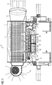
- FIG. 1 shows a generator 1 with a radiator 2.
- the radiator 2 has a fan 3 for sucking cooling air, which he blows in a heat exchanger 4.
- the air flows from there through an outlet 5 to the outside.
- an external cooling circuit is defined.
- the heat exchanger 4 cools through the outer cooling circuit 6 an inner, closed cooling circuit 7.
- the internal cooling circuit 7 is driven by a shaft fan 8, which is mounted on the B side of the shaft 9 of the generator 1.
- the inner cooling circuit flows through the heat exchanger starting from the fan 8 and penetrates on the A side (drive side) of the generator in the winding head space. There it flows around the winding head 10 and the winding circuit 31 and then flows through the rotor 11 and the stator 12, as will be explained in more detail below. Finally, the coolant (in particular air) flows through the winding head space on the B side (non-drive side) of the generator and again reaches the shaft fan 8.
- the rotor 11 has a laminated core 13, on whose end faces pressure rings 14 and 15 are mounted. In its axial direction, the rotor 11 is bisected by a radial cooling slot 16. This cooling slot 16 is formed here by a spacer with the discs 29.
- the rotor 11 also has axially extending cooling channels whose axial centers are located on two coaxial cylinders.
- the radial distance of the central axis of a cooling channel from the axis of the shaft 9 is referred to as the radial height of the cooling channel.
- the rotor 11 thus has a (third) cooling channel 17 and radially below, ie at a smaller radial height, a first axial cooling channel 18.
- On the right side of the radial cooling slot 16, which divides the rotor centrally, located in the Radial underneath is again in the same radial height as the second cooling channel 18, a fourth cooling channel 20.
- permanent magnets 21 are arranged in specially provided pockets distributed around the circumference. These are inserted from both end faces into the rotor and also shed from both end faces. Since the rotor 11 has only a central radial cooling slot 16, the insertion of the magnets and the casting is correspondingly easy to accomplish.
- the stator 12 has as a winding support a laminated core 22 which is traversed by numerous radially extending cooling slots 23.
- axially extending cooling fins 24 are integrally formed on the laminated core 22.
- the Cooling ribs 24 protrude in a star shape from the stator 12 and can be welded to the laminated core.
- each individual plate of the laminated core 22 has radially projecting extensions, so that the cooling fins 24 result in the packaging of the individual plates.
- a stator cooling flow 25 thus runs along the stator jacket exclusively in the axial direction.
- the axial cooling fins 24 of the stator are effectively cooled.
- At the B-side end of this first cooling flow 25 is still used to cool the winding head.
- a first cooling flow 28 is provided, which flows A-side into the first cooling channels 18 through the pressure plate 14.
- the radial cooling slot 16 of the rotor 11 is a spacer.
- three discs 29 are used as spacers.
- the discs 29 are formed differently and have recesses 30 in staggered positions.
- the first cooling flow 28 is combined with a second and third cooling flow 26, 25 in the front side space of the generator 1 in front of the wave fan 8.
- the first cooling flow 28 is thus in the first part of the rotor (left side in the FIG) through the cooler area (near the shaft) of the rotor. He hardly absorbs heat.
- On the right side of the rotor it is then led upwards and serves there for the effective cooling of the right rotor part.
- the left Half of the rotor part is, as explained above, primarily cooled by the second cooling flow 26.
- the second cooling flow 26 through the rotor is fed by a coolant or cooling air which has already cooled the winding head 10 and the winding circuit 31 in the A-side winding head space.
- This second cooling stream 26 penetrates through the A-side thrust washer 14 in the third cooling channel 17 of the rotor 11.
- the second coolant stream 26 is directed radially outward. It is distributed axially in the entire air gap 27 between the rotor 11 and stator 12. From there it is, since the pressure plates 14 and 15 have a slightly larger diameter than the rotor laminated core including the permanent magnets 21, urged radially outwardly through the cooling slots 23 of the stator.
- the second cooling or air flow 26 connects to the third cooling flow 25.
- the second cooling flow 26 thus ensures cooling of the in FIG. 1 shown left rotor part and the inner part of the stator over its entire axial length.
- the second cooling flow 26 thus has a substantially Z-shaped course. It flows first axially, then radially and finally again axially. Thus, sufficient cooling of the stator 12 can take place together with the linear stator cooling current, even if the rotor has only one radial cooling slot 16 and no plurality of such radial slots.
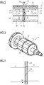
- FIG. 2 is the section of the rotor 11 with the cooling slot 16 of FIG. 1 shown enlarged.
- the rotor is divided axially by the cooling slot 16 into two sub-packages T1 and T2.
- the radial cooling slot 16 is formed by the discs 29, which serve as spacers between the two sub-packets T1 and T2. From the enlarged view of FIG. 2 It can be seen that the discs 29 have recesses or openings 30, so that a cooling flow can pass through the respective disc 29.
- the first cooling flow 28 passes through the cooling slot 16 or the discs 29 through openings 30 of one of the first cooling channels 18 in one of the second cooling channels 19. The center of each opening 30 therefore increases in the cooling flow direction from one disc to the next in the radial direction.
- the first cooling channel 18 is in flow communication with the second cooling channel 19.
- the discs 29 have further recesses 32, which allow the second cooling flow 26, which penetrates through the third cooling channels 17 in the rotor, to flow radially outward.
- the right-hand disk 29 facing the second cooling channel 19 seals the second cooling channel 19 with respect to the third cooling channel 17, so that the second cooling stream 26, which as a rule is already clearly heated when the cooling slot 16 is reached, does not penetrate into the second cooling channel 19.
- the first cooling flow 28 guided in the first sub-packet T1 can now cool the second sub-packet T2 in the region of the permanent magnets 21, because of the radial level change. in the outer area of the rotor.
- the flow directions of each cooling flow are naturally also conceivable in the opposite direction.
- FIG. 3 shows the rotor according to the invention in addition in a perspective view. So is, as already related to FIG. 1 has been explained, on the shaft 9 in addition to the sub-packets T1 and T2 of the rotor 11 on the B side of the shaft fan 8.
- the sub-packets T1 and T2 are separated by the radial cooling slot 16 from each other. From it, the second cooling stream 26 penetrates to the outside.
- the sub-packages T1 and T2 are offset from each other in the circumferential direction . In FIG. 4 this offset V is shown enlarged. By the offset V in the circumferential direction, the torque ripple of the rotor 11 is reduced. Nevertheless, the recesses 32 of the discs 29 ensure a sufficient radial cooling slot.
- the invention makes it possible with two or more sub-packages of a permanent-magnet-excited Runner to ensure ventilation. It is also possible to supply the rotor over the entire length with almost unused cooling air by using different cooling levels or levels. In addition, there are numerous other benefits. On the one hand, easy potting is possible because of the easy accessibility of the pockets of the permanent magnets. This results in a secure fixation of the magnets and a high-quality protection against corrosion. Furthermore, the rotor pressure plates 29, which separate the sub-packages of the rotor from each other, can be used for ventilation of the stator, since they have fan effect. Optionally, the cogging torque can be lowered according to the described structure by offsetting the partial packages. An additional advantage results from the fact that the laminations of the two sub-packages can be identical.
Landscapes
- Engineering & Computer Science (AREA)
- Power Engineering (AREA)
- Iron Core Of Rotating Electric Machines (AREA)
- Motor Or Generator Cooling System (AREA)
- Permanent Field Magnets Of Synchronous Machinery (AREA)
Claims (6)
- Machine électrique, comprenant- un rotor (11), qui a une fente (16) radiale de refroidissement unique, dans laquelle- le rotor (11) a des canaux de refroidissement, qui s'étendent axialement et qui débouchent dans sa fente (16) radiale de refroidissement, dans laquelle- des premiers canaux (18) de refroidissement, parmi les canaux de refroidissement s'étendant axialement, s'étendent, par leur axe central, à un niveau radial, par rapport à l'axe du rotor (11), plus bas que des deuxièmes canaux (19) de refroidissement, parmi les canaux de refroidissement s'étendant axialement et- dans la fente (16) radiale de refroidissement est disposée une entretoise, par laquelle un premier courant (28) de refroidissement peut être envoyé d'un premier canal (18) de refroidissement à un deuxième canal (19) de refroidissementcaractérisée en ce que- la fente (16) de refroidissement sépare le rotor (11) au milieu et- un deuxième courant (26) de refroidissement peut être introduit dans l'un des canaux de refroidissement s'étendant axialement et être dévié vers l'extérieur radialement par l'entretoise, les troisièmes canaux (17) de refroidissement se trouvant au même niveau radial que les deuxièmes canaux (19) de refroidissement.
- Machine électrique suivant la revendication 1, dans laquelle l'entretoise a plusieurs disques (29), qui ont chacun des ouvertures (30) de traversée et dans laquelle les ouvertures (30) de traversée des disques (29) sont telles qu'elles dévient le premier courant (28) de refroidissement dans la direction radiale.
- Machine électrique suivant l'une des revendications précédentes, dans laquelle le rotor (11) est excité par des aimants (21) permanents.
- Machine électrique suivant l'une des revendications 1 à 3, dans laquelle le rotor (11) a des barreaux de court-circuit.
- Machine électrique suivant l'une des revendications précédentes, dans laquelle un sous-paquet (T1), contenant les premiers canaux (18) de refroidissement, est décalé dans la direction périphérique par rapport à un sous-paquet (T2) contenant les deuxièmes canaux (19) de refroidissement.
- Procédé de refroidissement d'une machine électrique, ayant un rotor (11), par refroidissement du rotor par un premier courant (28) de refroidissement, qui est envoyé axialement dans le rotor (11), dans lequel- le premier courant (28) de refroidissement a, à l'entrée dans le rotor, dans la direction du flux, une ligne médiane, qui se trouve à un premier niveau radial par rapport à l'axe du rotor,- on dévie le premier courant (28) de refroidissement, au milieu du rotor dans une fente (16) radiale de refroidissement unique, par sa ligne médiane, à un deuxième niveau radial, plus haut que le premier niveau radial et- on envoie un deuxième courant (26) de refroidissement axialement dans le rotor (11) au deuxième niveau radial et on l'envoie vers l'extérieur radialement au milieu du rotor.
Applications Claiming Priority (2)
| Application Number | Priority Date | Filing Date | Title |
|---|---|---|---|
| DE102008064498A DE102008064498A1 (de) | 2008-12-23 | 2008-12-23 | Elektrische Maschine mit radial versetztem Kühlstrom und Kühlverfahren |
| PCT/EP2009/065717 WO2010072496A2 (fr) | 2008-12-23 | 2009-11-24 | Machine électrique à courant de refroidissement déplacé radialement, et procédé de refroidissement |
Publications (2)
| Publication Number | Publication Date |
|---|---|
| EP2368308A2 EP2368308A2 (fr) | 2011-09-28 |
| EP2368308B1 true EP2368308B1 (fr) | 2018-11-14 |
Family
ID=41785881
Family Applications (1)
| Application Number | Title | Priority Date | Filing Date |
|---|---|---|---|
| EP09771521.3A Active EP2368308B1 (fr) | 2008-12-23 | 2009-11-24 | Machine électrique à courant de refroidissement axial et déplacé radialement, et procédé correspondant |
Country Status (7)
| Country | Link |
|---|---|
| US (1) | US8686607B2 (fr) |
| EP (1) | EP2368308B1 (fr) |
| CN (1) | CN102265484B (fr) |
| DE (1) | DE102008064498A1 (fr) |
| ES (1) | ES2711321T3 (fr) |
| RU (1) | RU2516234C2 (fr) |
| WO (1) | WO2010072496A2 (fr) |
Families Citing this family (24)
| Publication number | Priority date | Publication date | Assignee | Title |
|---|---|---|---|---|
| DK2508749T3 (da) | 2011-04-04 | 2013-12-16 | Siemens Ag | Fremgangsmåde til montering af en elektrisk maskine |
| CN102185420A (zh) * | 2011-05-13 | 2011-09-14 | 东方电气(乐山)新能源设备有限公司 | 2mw风力发电机冷却系统 |
| US9476428B2 (en) * | 2011-06-01 | 2016-10-25 | R & D Dynamics Corporation | Ultra high pressure turbomachine for waste heat recovery |
| US9013075B2 (en) * | 2012-09-13 | 2015-04-21 | Siemens Industry, Inc. | Induction motors including vent spacers, rotor core assemblies including vent spacers, and methods of operating same |
| EP2941814B1 (fr) | 2013-02-15 | 2016-12-14 | Siemens Aktiengesellschaft | Machine electrique d'un stator sectorielle avec un bobinage à deux couches |
| DE102013002704A1 (de) | 2013-02-16 | 2014-08-21 | Audi Ag | Drehstabsystem für eine Fahrzeugachse eines zweispurigen Fahrzeuges |
| DE102013203911B3 (de) * | 2013-03-07 | 2014-08-28 | Siemens Aktiengesellschaft | 1Elektrische Maschine mit Frischluftkühlung der Abluftseite |
| JP5913160B2 (ja) * | 2013-03-11 | 2016-04-27 | トヨタ自動車株式会社 | 回転電機のロータ、および、回転電機 |
| CN103986280B (zh) * | 2014-03-21 | 2017-02-22 | 祁同刚 | 微通道式电机热模块冷却器 |
| KR101863481B1 (ko) | 2014-03-27 | 2018-05-31 | 프리펠 테크놀로지스, 엘엘씨 | 횡방향 수냉식 로터 및 스테이터를 구비하는 인덕션 로터 |
| US11255612B2 (en) | 2014-07-25 | 2022-02-22 | Enure, Inc. | Wound strip machine |
| US10756583B2 (en) | 2014-07-25 | 2020-08-25 | Enure, Inc. | Wound strip machine |
| DE112015003443T5 (de) | 2014-07-25 | 2017-04-06 | Prippell Technologies, Llc | Fluidgekühlte gewundene Streifenstruktur |
| EP3007328A1 (fr) | 2014-10-08 | 2016-04-13 | Siemens Aktiengesellschaft | Pièce active d'une machine électrique |
| DE112016000531T5 (de) | 2015-01-30 | 2017-11-02 | Prippell Technologies, Llc | Stator einer elektrischen Maschine mit flüssigkeitsgekühlten Zinken |
| EP3082202A1 (fr) | 2015-04-17 | 2016-10-19 | Siemens Aktiengesellschaft | Corps de bague de collecteur pour un rotor d'une machine dynamoélectrique tournante à excitation électrique |
| US10439350B2 (en) | 2015-05-29 | 2019-10-08 | Siemens Aktiengesellschaft | Arrangement for guiding and/or holding electrically conductive sliding contact elements |
| EP3142231A1 (fr) | 2015-09-08 | 2017-03-15 | ABB Technology AG | Générateur d'énergie électrique |
| EP3273078A1 (fr) * | 2016-07-19 | 2018-01-24 | Siemens Aktiengesellschaft | Palier magnetique actif et procede de refroidissement d'un palier magnetique actif |
| CN106451866B (zh) | 2016-12-05 | 2019-05-10 | 北京金风科创风电设备有限公司 | 电机转子支架以及电机 |
| JP2019149884A (ja) * | 2018-02-27 | 2019-09-05 | 本田技研工業株式会社 | 回転電機のロータ、及び、回転電機 |
| US11258322B2 (en) * | 2018-12-20 | 2022-02-22 | Teco-Westinghouse Motor Company | High speed induction machine |
| CN112713676B (zh) * | 2020-11-17 | 2021-12-10 | 北京交通大学 | 一种牵引电机轴向变截面定子通风孔的优化方法 |
| DE102021101937A1 (de) | 2021-01-28 | 2022-07-28 | Rolls-Royce Deutschland Ltd & Co Kg | Elektrische Maschine und Verfahren zur Reinigung eines Luftspalts in einer elektrischen Maschine |
Family Cites Families (16)
| Publication number | Priority date | Publication date | Assignee | Title |
|---|---|---|---|---|
| US3684906A (en) * | 1971-03-26 | 1972-08-15 | Gen Electric | Castable rotor having radially venting laminations |
| US3864906A (en) * | 1973-06-22 | 1975-02-11 | Vickers Ruwolt Pty Ltd | Chain link |
| US4301386A (en) * | 1977-08-12 | 1981-11-17 | General Electric Co. | Rotor laminae assembly for a cast rotor dynamoelectric machine |
| US4395816A (en) * | 1980-06-09 | 1983-08-02 | General Electric Co. | Method of making dynamoelectric machine rotor having cast conductors and radial coolant ducts |
| JPS58215954A (ja) * | 1982-06-07 | 1983-12-15 | Mitsubishi Electric Corp | 回転電機の回転子 |
| SU1718340A1 (ru) * | 1989-11-09 | 1992-03-07 | Е.В.Останькович, Д.Е.Почуйко и О.А.Чибалин | Электрическа машина |
| DE59700762D1 (de) * | 1996-04-17 | 1999-12-30 | Siemens Ag | Rotorwicklung für eine elektrische maschine |
| DE29913314U1 (de) * | 1999-04-30 | 1999-10-07 | Loher AG, 94099 Ruhstorf | Elektrische Maschine |
| JP2001086679A (ja) * | 1999-09-17 | 2001-03-30 | Hitachi Ltd | 回転電機 |
| DE10052427A1 (de) * | 2000-10-23 | 2002-05-02 | Alstom Switzerland Ltd | Schnelllaufende elektrische Maschine |
| DE10107298C1 (de) * | 2001-02-16 | 2002-07-04 | Krebs & Aulich Gmbh | Geschlossene elektrische Maschine mit Oberflächenkühlung |
| JP2003274618A (ja) * | 2002-03-14 | 2003-09-26 | Tma Electric Corp | 永久磁石回転子およびその製造方法 |
| RU2258295C2 (ru) * | 2003-05-05 | 2005-08-10 | Открытое Акционерное Общество "Силовые Машины - Зтл, Лмз, Электросила, Энергомашэкспорт" (Оао "Силовые Машины") | Способ газового охлаждения электрической машины и электрическая машина |
| DE10335038A1 (de) * | 2003-08-01 | 2005-03-10 | Siemens Ag | Elektrische Maschine mit Läuferkühlung und entsprechendes Kühlungsverfahren |
| JP4311182B2 (ja) * | 2003-12-08 | 2009-08-12 | 日産自動車株式会社 | 回転電機の回転子 |
| JP2008228523A (ja) * | 2007-03-15 | 2008-09-25 | Toyota Industries Corp | 回転電機およびその回転子 |
-
2008
- 2008-12-23 DE DE102008064498A patent/DE102008064498A1/de not_active Withdrawn
-
2009
- 2009-11-24 EP EP09771521.3A patent/EP2368308B1/fr active Active
- 2009-11-24 ES ES09771521T patent/ES2711321T3/es active Active
- 2009-11-24 RU RU2011130899/07A patent/RU2516234C2/ru not_active IP Right Cessation
- 2009-11-24 US US13/141,484 patent/US8686607B2/en active Active
- 2009-11-24 CN CN200980152270.1A patent/CN102265484B/zh active Active
- 2009-11-24 WO PCT/EP2009/065717 patent/WO2010072496A2/fr active Application Filing
Non-Patent Citations (1)
| Title |
|---|
| None * |
Also Published As
| Publication number | Publication date |
|---|---|
| WO2010072496A2 (fr) | 2010-07-01 |
| CN102265484B (zh) | 2015-09-23 |
| CN102265484A (zh) | 2011-11-30 |
| RU2011130899A (ru) | 2013-01-27 |
| WO2010072496A3 (fr) | 2011-02-03 |
| US8686607B2 (en) | 2014-04-01 |
| US20110254391A1 (en) | 2011-10-20 |
| ES2711321T3 (es) | 2019-05-03 |
| EP2368308A2 (fr) | 2011-09-28 |
| RU2516234C2 (ru) | 2014-05-20 |
| DE102008064498A1 (de) | 2010-07-01 |
Similar Documents
| Publication | Publication Date | Title |
|---|---|---|
| EP2368308B1 (fr) | Machine électrique à courant de refroidissement axial et déplacé radialement, et procédé correspondant | |
| DE102008064495B3 (de) | Elektrische Maschine mit mehreren Kühlströmen und Kühlverfahren | |
| EP0155405B1 (fr) | Dispositif pour le refroidissement indirect par gaz des enroulements statoriques et/ou pour le refroidissement direct par gaz de paquets de tôles feuilletées d'une machine dynamo-électrique en particulier turbogénérateurs à refroidissement à gaz | |
| EP3574567A1 (fr) | Machine synchrone à réluctance | |
| EP1552594A1 (fr) | Moteur synchrone a aimants permanents | |
| EP2104975A1 (fr) | Induit à aimants permanents présentant des fentes de refroidissement radiales et procédé de réalisation correspondant | |
| WO2005109610A1 (fr) | Unite modulaire stator | |
| WO2017032543A1 (fr) | Machine synchrone à réluctance | |
| EP2076956B1 (fr) | Système de refroidissement pour machines électriques tournantes à haut degré d'utilisation | |
| DE202011001558U1 (de) | Elektrische Maschine | |
| DE19919040C2 (de) | Synchronmaschine oder Asychronmaschine für große Windenergieanlagen | |
| EP1241772A1 (fr) | Machine électrique rotative refroidie par air | |
| EP1610446B1 (fr) | Moteur à courant continu sans balai | |
| EP1204193B1 (fr) | Système de refroidissement d'une machine électrique tournante à faible inertie | |
| DE10020705A1 (de) | Elektrische Maschine | |
| EP3813237B1 (fr) | Module de bobine pour une machine électrique | |
| DE102020122523A1 (de) | Gekühlter Rotor einer elektrischen Maschine | |
| DE10033799A1 (de) | Transversalflussmaschine | |
| DE10225221B4 (de) | Belüftung eines Ringmotors für eine Rohrmühle | |
| EP1032113A1 (fr) | Dispositif de refroidissement pour une machine électrique, notamment pour une machine à champ tournant | |
| WO1999046846A1 (fr) | Systeme de ventilation pour bobinage d'excitation de grandes machines a pole saillant | |
| EP4084288B1 (fr) | Module de bobine pour une machine électrique | |
| EP0903833A1 (fr) | Machine électrique avec rotor à cage d'écureil | |
| EP2230746B1 (fr) | Système de refroidissement d`un stator d`une machine électrique tournante sans carcasse | |
| WO2023046332A1 (fr) | Rotor pour une machine électrique tournante, machine électrique tournante, entraînement de capsule et embarcation nautique |
Legal Events
| Date | Code | Title | Description |
|---|---|---|---|
| PUAI | Public reference made under article 153(3) epc to a published international application that has entered the european phase |
Free format text: ORIGINAL CODE: 0009012 |
|
| 17P | Request for examination filed |
Effective date: 20110608 |
|
| AK | Designated contracting states |
Kind code of ref document: A2 Designated state(s): AT BE BG CH CY CZ DE DK EE ES FI FR GB GR HR HU IE IS IT LI LT LU LV MC MK MT NL NO PL PT RO SE SI SK SM TR |
|
| DAX | Request for extension of the european patent (deleted) | ||
| RAP1 | Party data changed (applicant data changed or rights of an application transferred) |
Owner name: SIEMENS AKTIENGESELLSCHAFT |
|
| RAP1 | Party data changed (applicant data changed or rights of an application transferred) |
Owner name: SIEMENS AKTIENGESELLSCHAFT |
|
| GRAP | Despatch of communication of intention to grant a patent |
Free format text: ORIGINAL CODE: EPIDOSNIGR1 |
|
| INTG | Intention to grant announced |
Effective date: 20180718 |
|
| GRAS | Grant fee paid |
Free format text: ORIGINAL CODE: EPIDOSNIGR3 |
|
| GRAA | (expected) grant |
Free format text: ORIGINAL CODE: 0009210 |
|
| AK | Designated contracting states |
Kind code of ref document: B1 Designated state(s): AT BE BG CH CY CZ DE DK EE ES FI FR GB GR HR HU IE IS IT LI LT LU LV MC MK MT NL NO PL PT RO SE SI SK SM TR |
|
| REG | Reference to a national code |
Ref country code: GB Ref legal event code: FG4D Free format text: NOT ENGLISH |
|
| REG | Reference to a national code |
Ref country code: CH Ref legal event code: EP Ref country code: AT Ref legal event code: REF Ref document number: 1065992 Country of ref document: AT Kind code of ref document: T Effective date: 20181115 |
|
| REG | Reference to a national code |
Ref country code: DE Ref legal event code: R096 Ref document number: 502009015456 Country of ref document: DE |
|
| REG | Reference to a national code |
Ref country code: IE Ref legal event code: FG4D Free format text: LANGUAGE OF EP DOCUMENT: GERMAN |
|
| REG | Reference to a national code |
Ref country code: NL Ref legal event code: MP Effective date: 20181114 |
|
| REG | Reference to a national code |
Ref country code: LT Ref legal event code: MG4D |
|
| PG25 | Lapsed in a contracting state [announced via postgrant information from national office to epo] |
Ref country code: LV Free format text: LAPSE BECAUSE OF FAILURE TO SUBMIT A TRANSLATION OF THE DESCRIPTION OR TO PAY THE FEE WITHIN THE PRESCRIBED TIME-LIMIT Effective date: 20181114 Ref country code: HR Free format text: LAPSE BECAUSE OF FAILURE TO SUBMIT A TRANSLATION OF THE DESCRIPTION OR TO PAY THE FEE WITHIN THE PRESCRIBED TIME-LIMIT Effective date: 20181114 Ref country code: BG Free format text: LAPSE BECAUSE OF FAILURE TO SUBMIT A TRANSLATION OF THE DESCRIPTION OR TO PAY THE FEE WITHIN THE PRESCRIBED TIME-LIMIT Effective date: 20190214 Ref country code: NO Free format text: LAPSE BECAUSE OF FAILURE TO SUBMIT A TRANSLATION OF THE DESCRIPTION OR TO PAY THE FEE WITHIN THE PRESCRIBED TIME-LIMIT Effective date: 20190214 Ref country code: IS Free format text: LAPSE BECAUSE OF FAILURE TO SUBMIT A TRANSLATION OF THE DESCRIPTION OR TO PAY THE FEE WITHIN THE PRESCRIBED TIME-LIMIT Effective date: 20190314 Ref country code: LT Free format text: LAPSE BECAUSE OF FAILURE TO SUBMIT A TRANSLATION OF THE DESCRIPTION OR TO PAY THE FEE WITHIN THE PRESCRIBED TIME-LIMIT Effective date: 20181114 Ref country code: FI Free format text: LAPSE BECAUSE OF FAILURE TO SUBMIT A TRANSLATION OF THE DESCRIPTION OR TO PAY THE FEE WITHIN THE PRESCRIBED TIME-LIMIT Effective date: 20181114 |
|
| REG | Reference to a national code |
Ref country code: ES Ref legal event code: FG2A Ref document number: 2711321 Country of ref document: ES Kind code of ref document: T3 Effective date: 20190503 |
|
| PG25 | Lapsed in a contracting state [announced via postgrant information from national office to epo] |
Ref country code: SE Free format text: LAPSE BECAUSE OF FAILURE TO SUBMIT A TRANSLATION OF THE DESCRIPTION OR TO PAY THE FEE WITHIN THE PRESCRIBED TIME-LIMIT Effective date: 20181114 Ref country code: NL Free format text: LAPSE BECAUSE OF FAILURE TO SUBMIT A TRANSLATION OF THE DESCRIPTION OR TO PAY THE FEE WITHIN THE PRESCRIBED TIME-LIMIT Effective date: 20181114 Ref country code: PT Free format text: LAPSE BECAUSE OF FAILURE TO SUBMIT A TRANSLATION OF THE DESCRIPTION OR TO PAY THE FEE WITHIN THE PRESCRIBED TIME-LIMIT Effective date: 20190314 Ref country code: GR Free format text: LAPSE BECAUSE OF FAILURE TO SUBMIT A TRANSLATION OF THE DESCRIPTION OR TO PAY THE FEE WITHIN THE PRESCRIBED TIME-LIMIT Effective date: 20190215 |
|
| REG | Reference to a national code |
Ref country code: CH Ref legal event code: PL |
|
| PG25 | Lapsed in a contracting state [announced via postgrant information from national office to epo] |
Ref country code: DK Free format text: LAPSE BECAUSE OF FAILURE TO SUBMIT A TRANSLATION OF THE DESCRIPTION OR TO PAY THE FEE WITHIN THE PRESCRIBED TIME-LIMIT Effective date: 20181114 Ref country code: CZ Free format text: LAPSE BECAUSE OF FAILURE TO SUBMIT A TRANSLATION OF THE DESCRIPTION OR TO PAY THE FEE WITHIN THE PRESCRIBED TIME-LIMIT Effective date: 20181114 Ref country code: IT Free format text: LAPSE BECAUSE OF FAILURE TO SUBMIT A TRANSLATION OF THE DESCRIPTION OR TO PAY THE FEE WITHIN THE PRESCRIBED TIME-LIMIT Effective date: 20181114 Ref country code: LU Free format text: LAPSE BECAUSE OF NON-PAYMENT OF DUE FEES Effective date: 20181124 Ref country code: PL Free format text: LAPSE BECAUSE OF FAILURE TO SUBMIT A TRANSLATION OF THE DESCRIPTION OR TO PAY THE FEE WITHIN THE PRESCRIBED TIME-LIMIT Effective date: 20181114 |
|
| REG | Reference to a national code |
Ref country code: DE Ref legal event code: R097 Ref document number: 502009015456 Country of ref document: DE |
|
| REG | Reference to a national code |
Ref country code: BE Ref legal event code: MM Effective date: 20181130 |
|
| REG | Reference to a national code |
Ref country code: IE Ref legal event code: MM4A |
|
| PG25 | Lapsed in a contracting state [announced via postgrant information from national office to epo] |
Ref country code: SK Free format text: LAPSE BECAUSE OF FAILURE TO SUBMIT A TRANSLATION OF THE DESCRIPTION OR TO PAY THE FEE WITHIN THE PRESCRIBED TIME-LIMIT Effective date: 20181114 Ref country code: RO Free format text: LAPSE BECAUSE OF FAILURE TO SUBMIT A TRANSLATION OF THE DESCRIPTION OR TO PAY THE FEE WITHIN THE PRESCRIBED TIME-LIMIT Effective date: 20181114 Ref country code: LI Free format text: LAPSE BECAUSE OF NON-PAYMENT OF DUE FEES Effective date: 20181130 Ref country code: CH Free format text: LAPSE BECAUSE OF NON-PAYMENT OF DUE FEES Effective date: 20181130 Ref country code: MC Free format text: LAPSE BECAUSE OF FAILURE TO SUBMIT A TRANSLATION OF THE DESCRIPTION OR TO PAY THE FEE WITHIN THE PRESCRIBED TIME-LIMIT Effective date: 20181114 Ref country code: EE Free format text: LAPSE BECAUSE OF FAILURE TO SUBMIT A TRANSLATION OF THE DESCRIPTION OR TO PAY THE FEE WITHIN THE PRESCRIBED TIME-LIMIT Effective date: 20181114 Ref country code: SM Free format text: LAPSE BECAUSE OF FAILURE TO SUBMIT A TRANSLATION OF THE DESCRIPTION OR TO PAY THE FEE WITHIN THE PRESCRIBED TIME-LIMIT Effective date: 20181114 |
|
| PLBE | No opposition filed within time limit |
Free format text: ORIGINAL CODE: 0009261 |
|
| STAA | Information on the status of an ep patent application or granted ep patent |
Free format text: STATUS: NO OPPOSITION FILED WITHIN TIME LIMIT |
|
| 26N | No opposition filed |
Effective date: 20190815 |
|
| PG25 | Lapsed in a contracting state [announced via postgrant information from national office to epo] |
Ref country code: IE Free format text: LAPSE BECAUSE OF NON-PAYMENT OF DUE FEES Effective date: 20181124 Ref country code: SI Free format text: LAPSE BECAUSE OF FAILURE TO SUBMIT A TRANSLATION OF THE DESCRIPTION OR TO PAY THE FEE WITHIN THE PRESCRIBED TIME-LIMIT Effective date: 20181114 Ref country code: FR Free format text: LAPSE BECAUSE OF NON-PAYMENT OF DUE FEES Effective date: 20190114 |
|
| PG25 | Lapsed in a contracting state [announced via postgrant information from national office to epo] |
Ref country code: BE Free format text: LAPSE BECAUSE OF NON-PAYMENT OF DUE FEES Effective date: 20181130 |
|
| REG | Reference to a national code |
Ref country code: AT Ref legal event code: MM01 Ref document number: 1065992 Country of ref document: AT Kind code of ref document: T Effective date: 20181124 |
|
| PG25 | Lapsed in a contracting state [announced via postgrant information from national office to epo] |
Ref country code: MT Free format text: LAPSE BECAUSE OF FAILURE TO SUBMIT A TRANSLATION OF THE DESCRIPTION OR TO PAY THE FEE WITHIN THE PRESCRIBED TIME-LIMIT Effective date: 20181114 Ref country code: AT Free format text: LAPSE BECAUSE OF NON-PAYMENT OF DUE FEES Effective date: 20181124 |
|
| PG25 | Lapsed in a contracting state [announced via postgrant information from national office to epo] |
Ref country code: TR Free format text: LAPSE BECAUSE OF FAILURE TO SUBMIT A TRANSLATION OF THE DESCRIPTION OR TO PAY THE FEE WITHIN THE PRESCRIBED TIME-LIMIT Effective date: 20181114 |
|
| PG25 | Lapsed in a contracting state [announced via postgrant information from national office to epo] |
Ref country code: HU Free format text: LAPSE BECAUSE OF FAILURE TO SUBMIT A TRANSLATION OF THE DESCRIPTION OR TO PAY THE FEE WITHIN THE PRESCRIBED TIME-LIMIT; INVALID AB INITIO Effective date: 20091124 Ref country code: MK Free format text: LAPSE BECAUSE OF NON-PAYMENT OF DUE FEES Effective date: 20181114 Ref country code: CY Free format text: LAPSE BECAUSE OF FAILURE TO SUBMIT A TRANSLATION OF THE DESCRIPTION OR TO PAY THE FEE WITHIN THE PRESCRIBED TIME-LIMIT Effective date: 20181114 |
|
| REG | Reference to a national code |
Ref country code: DE Ref legal event code: R081 Ref document number: 502009015456 Country of ref document: DE Owner name: FLENDER GMBH, DE Free format text: FORMER OWNER: SIEMENS AKTIENGESELLSCHAFT, 80333 MUENCHEN, DE |
|
| REG | Reference to a national code |
Ref country code: GB Ref legal event code: 732E Free format text: REGISTERED BETWEEN 20201210 AND 20201216 |
|
| REG | Reference to a national code |
Ref country code: ES Ref legal event code: PC2A Owner name: FLENDER GMBH Effective date: 20210223 |
|
| REG | Reference to a national code |
Ref country code: DE Ref legal event code: R082 Ref document number: 502009015456 Country of ref document: DE Representative=s name: MICHALSKI HUETTERMANN & PARTNER PATENTANWAELTE, DE |
|
| PGFP | Annual fee paid to national office [announced via postgrant information from national office to epo] |
Ref country code: GB Payment date: 20221125 Year of fee payment: 14 |
|
| PGFP | Annual fee paid to national office [announced via postgrant information from national office to epo] |
Ref country code: ES Payment date: 20230125 Year of fee payment: 14 |
|
| PGFP | Annual fee paid to national office [announced via postgrant information from national office to epo] |
Ref country code: DE Payment date: 20231127 Year of fee payment: 15 |
|
| GBPC | Gb: european patent ceased through non-payment of renewal fee |
Effective date: 20231124 |