EP2365249B1 - Procédé d'installation d'un conduit de cheminée pour une installation de chauffage dans une cheminée à gaz d'échappement et kit de montage - Google Patents
Procédé d'installation d'un conduit de cheminée pour une installation de chauffage dans une cheminée à gaz d'échappement et kit de montage Download PDFInfo
- Publication number
- EP2365249B1 EP2365249B1 EP20100002366 EP10002366A EP2365249B1 EP 2365249 B1 EP2365249 B1 EP 2365249B1 EP 20100002366 EP20100002366 EP 20100002366 EP 10002366 A EP10002366 A EP 10002366A EP 2365249 B1 EP2365249 B1 EP 2365249B1
- Authority
- EP
- European Patent Office
- Prior art keywords
- chimney
- pipe
- waste gas
- connection
- chimney pipe
- Prior art date
- Legal status (The legal status is an assumption and is not a legal conclusion. Google has not performed a legal analysis and makes no representation as to the accuracy of the status listed.)
- Active
Links
- 238000010438 heat treatment Methods 0.000 title claims description 46
- 238000000034 method Methods 0.000 title claims description 29
- 239000002912 waste gas Substances 0.000 title claims 17
- 238000009434 installation Methods 0.000 claims description 15
- 229920003023 plastic Polymers 0.000 claims description 14
- 239000004033 plastic Substances 0.000 claims description 14
- 239000002184 metal Substances 0.000 claims description 10
- 239000000463 material Substances 0.000 claims description 5
- 238000003780 insertion Methods 0.000 claims description 2
- 230000037431 insertion Effects 0.000 claims description 2
- 239000007789 gas Substances 0.000 description 20
- 230000001681 protective effect Effects 0.000 description 17
- 239000000725 suspension Substances 0.000 description 5
- 239000002033 PVDF binder Substances 0.000 description 3
- UGFAIRIUMAVXCW-UHFFFAOYSA-N Carbon monoxide Chemical compound [O+]#[C-] UGFAIRIUMAVXCW-UHFFFAOYSA-N 0.000 description 2
- 238000013459 approach Methods 0.000 description 2
- 230000005494 condensation Effects 0.000 description 2
- 238000009833 condensation Methods 0.000 description 2
- 239000003546 flue gas Substances 0.000 description 2
- 239000006260 foam Substances 0.000 description 2
- 229920002981 polyvinylidene fluoride Polymers 0.000 description 2
- 238000012360 testing method Methods 0.000 description 2
- 229910000831 Steel Inorganic materials 0.000 description 1
- 230000009471 action Effects 0.000 description 1
- 239000011449 brick Substances 0.000 description 1
- 230000008878 coupling Effects 0.000 description 1
- 238000010168 coupling process Methods 0.000 description 1
- 238000005859 coupling reaction Methods 0.000 description 1
- 230000007423 decrease Effects 0.000 description 1
- 238000013461 design Methods 0.000 description 1
- 238000011161 development Methods 0.000 description 1
- 230000018109 developmental process Effects 0.000 description 1
- 239000013013 elastic material Substances 0.000 description 1
- 239000003517 fume Substances 0.000 description 1
- 238000007689 inspection Methods 0.000 description 1
- 239000000696 magnetic material Substances 0.000 description 1
- 230000008569 process Effects 0.000 description 1
- 230000007480 spreading Effects 0.000 description 1
- 229910001220 stainless steel Inorganic materials 0.000 description 1
- 239000010935 stainless steel Substances 0.000 description 1
- 239000010959 steel Substances 0.000 description 1
- 239000002918 waste heat Substances 0.000 description 1
Images

Classifications
-
- F—MECHANICAL ENGINEERING; LIGHTING; HEATING; WEAPONS; BLASTING
- F23—COMBUSTION APPARATUS; COMBUSTION PROCESSES
- F23J—REMOVAL OR TREATMENT OF COMBUSTION PRODUCTS OR COMBUSTION RESIDUES; FLUES
- F23J11/00—Devices for conducting smoke or fumes, e.g. flues
- F23J11/12—Smoke conduit systems for factories or large buildings
-
- F—MECHANICAL ENGINEERING; LIGHTING; HEATING; WEAPONS; BLASTING
- F23—COMBUSTION APPARATUS; COMBUSTION PROCESSES
- F23J—REMOVAL OR TREATMENT OF COMBUSTION PRODUCTS OR COMBUSTION RESIDUES; FLUES
- F23J2211/00—Flue gas duct systems
- F23J2211/40—Chimney with internal flue pipe system
Definitions
- the invention relates to a method for installing a chimney pipe for a heating system in an exhaust stack.
- a method is for example from FR 2 818 965 known.
- multi-storey buildings for example residential buildings
- have an exhaust stack which serves for the discharge or discharge of the exhaust gases of a variety of heating systems.
- the heating systems can be installed in particular in apartments or residential units on different floors and be coupled via connection points with the exhaust stack such that the exhaust gases are introduced into the exhaust stack via the connection points.
- the present invention seeks to develop a method for installing a chimney pipe for a heating system in an exhaust stack, which allows a simple, subsequent installation of a chimney pipe in an existing flue without this essential structural changes in the exhaust stack or high investment costs are required or the operation of older, conventional heating systems is disturbed.
- This object is achieved by a method having the features of claim 1.
- the at least one auxiliary means comprises a first part which is introduced from the side of the connection region into the exhaust gas chimney, from the chimney end a second part of the first auxiliary means into the exhaust gas Is introduced exhaust stack and that the two ends in the exhaust stack contact each other, such that between the two parts made a mechanical load-bearing connection becomes.
- the first part has at least one flexible part, in particular in the form of an extension rod and at least on the side at which the connection is made with the second part, a first magnetically effective Having area in the form of a metal plate and that the second part on the side facing the first part has a second magnetically active area, such that attract the two magnetically active areas.
- the two respective end portions of the first and second parts can be positioned relative to one another in a relatively simple manner, since in the presence of a certain magnetic attraction the two parts approach and contact one another.
- the handling of the two parts of the first auxiliary element is facilitated if the first part is in the form of an extension rod, if the second part has at least one flexible element in the form of a cord or a band, if the end of the cord inserted into the fume hood or the band is provided with a ballast or the band tightening ballast element, and when the ballast element or the ballast element facing the end has a magnetic element.
- the required length for the chimney pipe can be determined when a tape measure is used as a band and, if the required length of the chimney pipe is determined after establishing the connection between the chimney end and the connection area by means of the tape measure.
- the read Value of the tape measure an additional length is added as a security, so that any existing bends or bends, which are bridged by the tape measure on the shortest path, can be easily bridged by the chimney pipe having a certain diameter also.
- the method additionally comprises attaching at least one adapter plate to the side of the chimney end and attaching the chimney pipe to the adapter plate.
- the chimney pipe is at least partially flexible.
- the area of the protective element can be bridged or passed through relatively easily.
- the chimney pipe consists at least partially of plastic, in particular of PVDF.
- the invention also advantageously comprises in addition the method step of checking the tightness of the chimney pipe after its installation between the chimney end and the connection point.
- This will damage any damage that may occur during installation of the chimney pipe, e.g. could be detected by contact or by contact with sharp edges or the like, reliably detected and thus prevents commissioning.
- the check is carried out by means of a positive pressure source, wherein the two ends of the chimney pipe are closed and the chimney pipe is exposed to an overpressure. If damage has been set in the wall of the chimney pipe during assembly or installation of the chimney pipe, such damage can be easily detected or noticed by a drop in pressure.
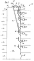
- each of the connection regions 27 is assigned a protective element 30.
- the perpendicular to the plane of the Fig. 1 over the entire exhaust duct 20 extending protective element 30 is preferably designed as a rampart, has a wall portion 31 which extends approximately parallel to the wall 26 of the exhaust duct 20 and extends from the respective floor 11 to 16 on the floor 11 to 16 also upwards ,
- protective element 30 is an increased fire safety in conventional heating systems 19 causes or achieved.
- An exhaust gas fireplace 1 described so far with the protective elements 30 is referred to in France as a so-called "shunt fireplace".
- a chimney end 34 in particular the outlet of the exhaust chimney 1 is referred to the environment.
- the respective ends 33 of the three chimney pipes 25 are arranged in receptacles 35, 36 of an adapter plate 37a, 37b made of steel or plastic, the receptacles 35, 36 being designed in particular as through-holes. Further, the two adapter plates 37a, 37b placed on the chimney end 34 and preferably connected to the chimney end 34 fixed.
- two adapter plates 37a, 37b are provided which cover a total of only a portion of the opening cross-section of the exhaust duct 20, so over the non-covered by the adapter plates 37a, 37b cross-section the exhaust gas chimney 20, the exhaust gases of the (conventional) heating systems 21 can be discharged to the environment.
- each of the chimney pipes 25 is assigned to a special adapter plate 37a, 37b.
- a special adapter plate 37a, 37b it is provided that between one and three adapter plates 37a, 37b, 37c are provided.
- each of the adapter plates 37a, 37b, 37c serves to accommodate a maximum of two chimney tubes 25.
- the case is shown in which all six floors 11 to 16 are equipped with (more modern) heating systems 22.
- all three adapter plates 37a, 37b and 37c are used. It is essential here that the adapter plate 37a, which has the smallest distance to the wall 26 of the exhaust shaft 20, the two (upper) floors 15 and 16, the (middle) adapter plate 37b the two (middle) floors 13 and 14 and the farthest from the wall 26 remote adapter plate 37 c is assigned to the two (lower) floors 11 and 12.
- the corresponding adapter plate 37a to 37c used or installed.
- the available cross section of the exhaust duct 20 is optimally utilized for the guidance of the chimney pipes 25 and, in the case of a mixed operation with heating systems 21 and 22, the exhaust ducting of the heating systems 21 is optimized.
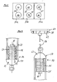
- the mounting kit 40 which allows a first aid 41 to provide a connection between the fireplace end 34 and the corresponding terminal portion 27.
- the first aid 41 has for this purpose a measuring tape 42, at one end of a ballast weight 43 is arranged.
- the mounting set 40 comprises a second part designed as a sheet metal plate 44 with rollers 45 and a flexible extension bar 46 with a length of about 3m, which manually (together with the metal plate 44) can be passed through the connection portion 27, wherein it As a result of its flexible extension rod 46 the shape of the protective element 30 adapts or this can happen by the sheet metal plate 44, for example, at the Wall 26 of the exhaust duct 20 or rolls along the opposite wall of the exhaust duct 20 along.
- a magnetic element 47 is additionally arranged on the end of the measuring tape 42 facing the ballast weight 43.
- the ballast weight 43 itself consists of magnetic material.
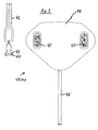
- connection between the chimney end 34 and the connection region 27 takes place according to the Fig. 5 in that the end of the measuring tape 42 assigned to the ballast weight 43 passes through the receptacle 35 and the measuring tape 42 is lowered in the direction of the protective element 30 of the floor 16.
- the metal plate 44 was spent in the direction of the end of the fireplace 34 via the connection area 27 of the floor 16.
- a mechanical connection between the magnetic element 47 or the measuring tape 42 and the metal plate 44 takes place due to the magnetic attraction.
- the sheet metal plate 44 can be pulled down with the end of the measuring tape 42 in the region of the connection region 27, so that the measuring tape 42 together with the ballast weight 43 passes through the connection region 27.
- the value for the length of the connection between the connection region 27 and the chimney end 34 or the adapter plate 37a assigned to the floor 16 is now read off at the chimney end 34 on the measuring tape 42, whereby the required length for the chimney pipe 25 can be determined.
- this determined value can be added an additional length, so as to ensure in each case a sufficient length of the chimney pipe 25 and to facilitate the subsequent assembly of the ends 32, 33 of the chimney pipe 25.
- the adapter element 52 which also serves to check the tightness of the chimney pipe 25, has a protective cone 53 and a cylindrically shaped receiving and expanding section 54.
- the diameter of the receiving and expanding portion 54 is preferably adjustable with the interposition of a 6-8 cm long foam tube 56 by means of a wedge 55, so that the with its inner circumference on the receiving and spreading portion 54 deferred until the cone 53 end 32 of the chimney pipe 25th mechanically fixed and sealed with the chimney pipe 25 is connectable.
- the chimney pipe 25 is preferably made of plastic, here in particular at least partially made of PVDF (polyvinylidene fluoride). In particular, it has at least one partial area, which is designed to be flexible, such that it can easily pass through the protective element 30 in the exhaust shaft 20. Preferably, the chimney pipe 25 is flexible over its entire length (flexible tube).
- PVDF polyvinylidene fluoride
- the chimney pipe 25 can be provided with fastening elements which make it possible to fix the chimney pipe 25 to the connection region 27.
- the other end 33 of the chimney pipe 25 may be located within the exhaust duct 20, being secured by the securing plate.
- the end 32 can be drawn relatively far into the connection region 27, in order to facilitate the assembly of the fastening elements (not shown) for the end 32 of the chimney pipe 25, without the chimney pipe 25 having to be specially extended for this purpose.
- the end 33 of the chimney pipe 25 is pulled upwards by the receptacle 35 and the cable 59 is connected to a spring balance 65, wherein previously the suspension ring 38 has been pushed onto the outer circumference of the chimney pipe 25.
- the second adapter element 57 may also be connected directly to the spring balance 65 become. Then, a defined tensile force is exerted on the second adapter element 57 by means of the spring balance 65.
- the chimney pipe 25 between the connection region 27 and the chimney end 34 or the adapter plate 37 a is stretched or its length minimized ( Figure 7 ). This is done in particular with regard to any elongation of the chimney pipe 25 during operation of the heating systems 21, 22 as a result of thermal expansion.
Landscapes
- Engineering & Computer Science (AREA)
- Architecture (AREA)
- Mechanical Engineering (AREA)
- General Engineering & Computer Science (AREA)
- Chimneys And Flues (AREA)
Claims (14)
- Procédé d'installation d'un conduit de cheminée (25) pour une installation de chauffage (22) dans une cheminée de gaz d'échappement (1), la cheminée de gaz d'échappement (1) présentant un conduit de gaz d'échappement (20) avec une extrémité supérieure de cheminée (34) disposée en liaison fonctionnelle avec l'environnement d'un bâtiment (10) et une région de raccordement (27), qui est disposée dans une paroi (26) de la cheminée de gaz d'échappement (1), le conduit de cheminée (25) étant disposé au moins entre l'extrémité de la cheminée (34) et la région de raccordement (27), et l'installation du conduit de cheminée (25) comprenant les étapes suivantes :- fabrication d'une liaison entre l'extrémité de la cheminée (34) et la région de raccordement (27) au moyen d'au moins un moyen auxiliaire (41, 51),- liaison de l'au moins un moyen auxiliaire (41, 51) au conduit de cheminée (25) du côté de l'extrémité de la cheminée (34) ou de la région de raccordement (27),- introduction du conduit de cheminée (25) dans la cheminée de gaz d'échappement (1) au moyen de l'au moins un moyen auxiliaire (41, 51), et- liaison de l'extrémité respective (32, 33) du conduit de cheminée (25) dans la région de l'extrémité de la cheminée (34) à la cheminée de gaz d'échappement (1) ou à la région de raccordement (27),caractérisé en ce que
l'au moins un moyen auxiliaire (41) comprend une première partie (44), qui est introduite depuis le côté de la région de raccordement (27) dans la cheminée de gaz d'échappement (1), en ce qu'une deuxième partie (42) du premier moyen auxiliaire (41) est introduite dans la cheminée de gaz d'échappement (1) depuis l'extrémité de la cheminée (34), et en ce que les deux extrémités des parties (42, 44) dans la cheminée de gaz d'échappement (1) sont en contact l'une avec l'autre de telle sorte qu'entre les deux parties (42, 44) soit établie une liaison pouvant être sollicitée mécaniquement. - Procédé selon la revendication 1,
caractérisé en ce que
la première partie (44) est reliée à un élément flexible (46) et présente, au moins du côté sur lequel la liaison avec la deuxième partie (42) est établie, une première région magnétiquement active et en ce que la deuxième partie (42) présente, sur le côté tourné vers la première partie (44), une deuxième région magnétiquement active (47) de telle sorte que les deux régions magnétiquement actives (44, 47) s'attirent. - Procédé selon les revendications 1 ou 2,
caractérisé en ce que
la première partie (44) est réalisée sous forme de plaque de tôle, en ce que la deuxième partie présente au moins un élément flexible en forme de cordon ou de bande (42), en ce que l'extrémité du cordon ou de la bande (42) introduite dans la cheminée d'aspiration (1) est pourvue d'un poids de ballast (43) tendant le cordon ou la bande (42) et en ce que le poids de ballast (43) ou l'extrémité de la plaque de tôle (44) tournée vers le poids de ballast (43) présente un élément magnétique (47). - Procédé selon la revendication 3,
caractérisé en ce que
l'on utilise comme bande un mètre-ruban (42) et en ce que la longueur requise du conduit de cheminée (25) après l'établissement de la liaison entre l'extrémité de la cheminée (34) et la région de raccordement (27) est déterminée au moyen du mètre-ruban (42). - Procédé selon l'une quelconque des revendications 1 à 4,
caractérisé en ce que
le procédé comprend en outre l'application d'au moins une plaque d'adaptateur (37a, 37b, 37c) sur le côté de l'extrémité de la cheminée (34) et la fixation du conduit de cheminée (25) sur l'une des plaques d'adaptateur (37a, 37b, 37c). - Procédé selon l'une quelconque des revendications 1 à 5,
caractérisé en ce
qu'après l'établissement de la liaison entre l'extrémité de la cheminée (34) et la région de raccordement (27) au moyen de l'au moins un premier moyen auxiliaire (41), l'au moins un premier moyen auxiliaire (41) est remplacé par un deuxième moyen auxiliaire, en particulier sous forme de cordon en plastique (51), le cordon en plastique (51) présentant une telle solidité qu'il porte sans destruction au moins le poids du conduit de cheminée (25). - Procédé selon l'une quelconque des revendications 1 à 6,
caractérisé en ce que
le conduit de cheminée (25) est introduit dans la cheminée de gaz d'échappement (1) depuis le côté de l'extrémité de la cheminée (34), en ce que l'extrémité (32) du conduit de cheminée (25) tournée vers la région de raccordement (27) est reliée à un premier élément d'adaptateur (52) et en ce qu'après la liaison de l'extrémité (32) du conduit de cheminée (25) à la région de raccordement (27), l'extrémité (33) du conduit de cheminée (25) associée à l'extrémité de cheminée (34) est reliée au moins indirectement à l'extrémité de la cheminée (34). - Procédé selon la revendication 7,
caractérisé en ce que
le conduit de cheminée (25) est réalisé de manière au moins partiellement flexible. - Procédé selon les revendications 7 ou 8,
caractérisé en ce que
le conduit de cheminée (25) se compose au moins en partie de plastique, en particulier de PVDF (fluorure de polyvinylidène). - Procédé selon l'une quelconque des revendications 7 à 9,
caractérisé en ce que
le conduit de cheminée (25) est exposé à une contrainte de traction avant la liaison à l'extrémité de la cheminée (34), et en ce que la liaison du conduit de cheminée (25) à l'extrémité de la cheminée (34) a lieu sous contrainte de traction. - Procédé selon l'une quelconque des revendications 1 à 10,
caractérisé en ce que
le procédé comprend en outre l'étape de procédé de contrôle de l'étanchéité du conduit de cheminée (25) après son montage entre l'extrémité de la cheminée (34) et le point de raccordement (27). - Procédé selon la revendication 11,
caractérisé en ce que
le contrôle a lieu au moyen d'une source de surpression (68), les deux extrémités (32, 33) du conduit de cheminée (25) étant fermées et le conduit de cheminée (25) étant exposé à une surpression. - Procédé selon l'une quelconque des revendications 5 à 12,
caractérisé en ce que
lors de l'installation de plusieurs conduits de cheminée (25), les extrémités (33) des conduits de cheminée (25) tournées vers l'extrémité de la cheminée (34) sont associées à chaque fois à des logements spéciaux (35, 36) dans l'élément d'adaptateur (37a, 37b, 37c). - Ensemble de montage (40) pour l'utilisation dans un procédé d'installation d'un conduit de cheminée (25) pour une installation de chauffage (22) dans une cheminée de gaz d'échappement (1) selon l'une quelconque des revendications 1 à 13, dans lequel l'ensemble de montage (40) comprend au moins un premier moyen auxiliaire (41) pour établir une liaison entre l'extrémité de la cheminée (34) et la région de raccordement (27) ainsi que pour l'introduction du conduit de cheminée dans la cheminée de gaz d'échappement, des moyens de fixation d'une extrémité (32) du conduit de cheminée (25) à la région de raccordement (27) et des moyens pour la liaison au moins indirecte de l'autre extrémité (33) du conduit de cheminée (25) à l'extrémité de la cheminée (34),
caractérisé en ce que
l'au moins un moyen auxiliaire (41) comprend une première partie (44), qui est introduite depuis le côté de la région de raccordement (27) dans la cheminée de gaz d'échappement (1), en ce qu'une deuxième partie (42) du premier moyen auxiliaire (41) est introduite dans la cheminée de gaz d'échappement (1) depuis l'extrémité de la cheminée (34), et en ce que les deux extrémités des parties (42, 44) dans la cheminée de gaz d'échappement (1) sont en contact l'une avec l'autre de telle sorte qu'entre les deux parties (42, 44) soit établie une liaison pouvant être sollicitée mécaniquement.
Priority Applications (1)
| Application Number | Priority Date | Filing Date | Title |
|---|---|---|---|
| EP20100002366 EP2365249B1 (fr) | 2010-03-08 | 2010-03-08 | Procédé d'installation d'un conduit de cheminée pour une installation de chauffage dans une cheminée à gaz d'échappement et kit de montage |
Applications Claiming Priority (1)
| Application Number | Priority Date | Filing Date | Title |
|---|---|---|---|
| EP20100002366 EP2365249B1 (fr) | 2010-03-08 | 2010-03-08 | Procédé d'installation d'un conduit de cheminée pour une installation de chauffage dans une cheminée à gaz d'échappement et kit de montage |
Publications (2)
| Publication Number | Publication Date |
|---|---|
| EP2365249A1 EP2365249A1 (fr) | 2011-09-14 |
| EP2365249B1 true EP2365249B1 (fr) | 2013-05-29 |
Family
ID=42312840
Family Applications (1)
| Application Number | Title | Priority Date | Filing Date |
|---|---|---|---|
| EP20100002366 Active EP2365249B1 (fr) | 2010-03-08 | 2010-03-08 | Procédé d'installation d'un conduit de cheminée pour une installation de chauffage dans une cheminée à gaz d'échappement et kit de montage |
Country Status (1)
| Country | Link |
|---|---|
| EP (1) | EP2365249B1 (fr) |
Cited By (1)
| Publication number | Priority date | Publication date | Assignee | Title |
|---|---|---|---|---|
| EP3839343A1 (fr) | 2019-12-19 | 2021-06-23 | Societe Exploitation Tolerie Emaillerie Nantaise | Ensemble en kit de conduit collectif a double flux |
Families Citing this family (2)
| Publication number | Priority date | Publication date | Assignee | Title |
|---|---|---|---|---|
| DE102012112236B4 (de) | 2012-12-13 | 2024-10-24 | Technaflon Kaminsysteme AG | Verfahren zur Installation eines Kaminrohrs für eine Heizungsanlage in einem Abgaskamin und Hilfsmittel zum Durchführen des Verfahrens |
| GB2524740A (en) * | 2014-03-31 | 2015-10-07 | Michael Davy Wadge | Device and method relating to the installation of a liner in a chimney or flue |
Family Cites Families (4)
| Publication number | Priority date | Publication date | Assignee | Title |
|---|---|---|---|---|
| IT1042501B (it) * | 1977-08-11 | 1980-01-30 | Marinni Battista S P A Impresa | Cimini e sud matoro li costruzione |
| US6029655A (en) * | 1998-04-27 | 2000-02-29 | Hussong Manufacturing Co., Inc. | Modular gas fireplace insert |
| DE29815970U1 (de) * | 1998-09-08 | 1999-03-18 | Technaflon AG, Tägerwilen | Kaminrohr |
| FR2818965B1 (fr) * | 2001-01-04 | 2003-05-30 | Michel Gautier | Appareil pour le gainage interieur de conduits |
-
2010
- 2010-03-08 EP EP20100002366 patent/EP2365249B1/fr active Active
Cited By (1)
| Publication number | Priority date | Publication date | Assignee | Title |
|---|---|---|---|---|
| EP3839343A1 (fr) | 2019-12-19 | 2021-06-23 | Societe Exploitation Tolerie Emaillerie Nantaise | Ensemble en kit de conduit collectif a double flux |
Also Published As
| Publication number | Publication date |
|---|---|
| EP2365249A1 (fr) | 2011-09-14 |
Similar Documents
| Publication | Publication Date | Title |
|---|---|---|
| EP2365249B1 (fr) | Procédé d'installation d'un conduit de cheminée pour une installation de chauffage dans une cheminée à gaz d'échappement et kit de montage | |
| EP0437260A1 (fr) | Chemise en céramique pour intérieur de cheminée. | |
| EP2365248B1 (fr) | Cheminée de fumées pour installations de chauffage et tuyau de cheminée pour une telle cheminée | |
| DE102012112852B4 (de) | Rohrbogen zur Abgasführung in Heizungsanlagen | |
| EP0443223B1 (fr) | Section tubulaire pour conduite tubulaire à plusieurs parties | |
| BE1021800B1 (de) | Verfahren zur installation eines kaminrohrs für eine heizungsanlage in einem abgaskamin und hilfsmittel zum durchführen des verfahrens | |
| DE202015002187U1 (de) | Stütze und Klemmteile zum Montieren von Bauelementen, insbesondere im Trockenbau und für die Überkopfmontage | |
| AT522944B1 (de) | Dichtungsanordnung und Rohranordnung | |
| EP2607786B1 (fr) | Agencement avec un coude de tube pour transport de gaz d'échappement dans des installations de chauffage | |
| EP0289783B1 (fr) | Système de montage pour l'installation d'un système de tuyaux pour gaz de combustion dans une cheminée | |
| DE102011054617A1 (de) | Vorrichtung zum zeitweiligen Befestigen einer Rohreinheit | |
| DE102017207053B4 (de) | Abgasrohr sowie Verfahren zum Ablängen eines Abgasrohres | |
| EP0344151B1 (fr) | Moyen pour commander a distance l'introduction d'un revetement pour la reparation des conduites | |
| AT505255B1 (de) | Schornstein | |
| DE102007026729A1 (de) | Vorrichtung zur Durchführung einer Rohrleitung oder dergleichen durch ein Dach | |
| EP0668463A1 (fr) | Dispositif d'espacement | |
| DE10254397B4 (de) | Universalschlauchkupplung | |
| DE19839920A1 (de) | Vorrichtung zur Brandabschottung einer Rohrleitung | |
| DE19939398A1 (de) | Muffenrohranordnung für eine Abgasleitung und Zentriervorrichtung hierfür | |
| DE10115676B4 (de) | Verfahren und Vorrichtung zum nachträglichen Einbau eines Gasströmungswächters in eine Hausanschlußleitung | |
| DE20014625U1 (de) | Vorrichtung zur Prüfung von Rohrleitungen | |
| DE4014964A1 (de) | Verfahren zum einbau von formstuecken in das rauchrohr eines kamins | |
| DE1683736C (de) | Schornstein oder Luftschacht | |
| DE202020106329U1 (de) | Fallrohrprovisorium | |
| EP1431659A1 (fr) | Connection pour tuyaux possédant une extremité à diamètre non cylindrique mais continu |
Legal Events
| Date | Code | Title | Description |
|---|---|---|---|
| PUAI | Public reference made under article 153(3) epc to a published international application that has entered the european phase |
Free format text: ORIGINAL CODE: 0009012 |
|
| AK | Designated contracting states |
Kind code of ref document: A1 Designated state(s): AT BE BG CH CY CZ DE DK EE ES FI FR GB GR HR HU IE IS IT LI LT LU LV MC MK MT NL NO PL PT RO SE SI SK SM TR |
|
| AX | Request for extension of the european patent |
Extension state: AL BA ME RS |
|
| 17P | Request for examination filed |
Effective date: 20120314 |
|
| GRAP | Despatch of communication of intention to grant a patent |
Free format text: ORIGINAL CODE: EPIDOSNIGR1 |
|
| GRAS | Grant fee paid |
Free format text: ORIGINAL CODE: EPIDOSNIGR3 |
|
| GRAA | (expected) grant |
Free format text: ORIGINAL CODE: 0009210 |
|
| AK | Designated contracting states |
Kind code of ref document: B1 Designated state(s): AT BE BG CH CY CZ DE DK EE ES FI FR GB GR HR HU IE IS IT LI LT LU LV MC MK MT NL NO PL PT RO SE SI SK SM TR |
|
| REG | Reference to a national code |
Ref country code: GB Ref legal event code: FG4D Free format text: NOT ENGLISH |
|
| REG | Reference to a national code |
Ref country code: CH Ref legal event code: EP |
|
| REG | Reference to a national code |
Ref country code: AT Ref legal event code: REF Ref document number: 614653 Country of ref document: AT Kind code of ref document: T Effective date: 20130615 |
|
| REG | Reference to a national code |
Ref country code: IE Ref legal event code: FG4D Free format text: LANGUAGE OF EP DOCUMENT: GERMAN |
|
| REG | Reference to a national code |
Ref country code: DE Ref legal event code: R096 Ref document number: 502010003395 Country of ref document: DE Effective date: 20130725 |
|
| REG | Reference to a national code |
Ref country code: LT Ref legal event code: MG4D |
|
| PG25 | Lapsed in a contracting state [announced via postgrant information from national office to epo] |
Ref country code: SI Free format text: LAPSE BECAUSE OF FAILURE TO SUBMIT A TRANSLATION OF THE DESCRIPTION OR TO PAY THE FEE WITHIN THE PRESCRIBED TIME-LIMIT Effective date: 20130529 Ref country code: SE Free format text: LAPSE BECAUSE OF FAILURE TO SUBMIT A TRANSLATION OF THE DESCRIPTION OR TO PAY THE FEE WITHIN THE PRESCRIBED TIME-LIMIT Effective date: 20130529 Ref country code: IS Free format text: LAPSE BECAUSE OF FAILURE TO SUBMIT A TRANSLATION OF THE DESCRIPTION OR TO PAY THE FEE WITHIN THE PRESCRIBED TIME-LIMIT Effective date: 20130929 Ref country code: PT Free format text: LAPSE BECAUSE OF FAILURE TO SUBMIT A TRANSLATION OF THE DESCRIPTION OR TO PAY THE FEE WITHIN THE PRESCRIBED TIME-LIMIT Effective date: 20130930 Ref country code: NO Free format text: LAPSE BECAUSE OF FAILURE TO SUBMIT A TRANSLATION OF THE DESCRIPTION OR TO PAY THE FEE WITHIN THE PRESCRIBED TIME-LIMIT Effective date: 20130829 Ref country code: FI Free format text: LAPSE BECAUSE OF FAILURE TO SUBMIT A TRANSLATION OF THE DESCRIPTION OR TO PAY THE FEE WITHIN THE PRESCRIBED TIME-LIMIT Effective date: 20130529 Ref country code: GR Free format text: LAPSE BECAUSE OF FAILURE TO SUBMIT A TRANSLATION OF THE DESCRIPTION OR TO PAY THE FEE WITHIN THE PRESCRIBED TIME-LIMIT Effective date: 20130830 Ref country code: LT Free format text: LAPSE BECAUSE OF FAILURE TO SUBMIT A TRANSLATION OF THE DESCRIPTION OR TO PAY THE FEE WITHIN THE PRESCRIBED TIME-LIMIT Effective date: 20130529 Ref country code: ES Free format text: LAPSE BECAUSE OF FAILURE TO SUBMIT A TRANSLATION OF THE DESCRIPTION OR TO PAY THE FEE WITHIN THE PRESCRIBED TIME-LIMIT Effective date: 20130909 |
|
| REG | Reference to a national code |
Ref country code: NL Ref legal event code: VDEP Effective date: 20130529 |
|
| PG25 | Lapsed in a contracting state [announced via postgrant information from national office to epo] |
Ref country code: PL Free format text: LAPSE BECAUSE OF FAILURE TO SUBMIT A TRANSLATION OF THE DESCRIPTION OR TO PAY THE FEE WITHIN THE PRESCRIBED TIME-LIMIT Effective date: 20130529 Ref country code: BG Free format text: LAPSE BECAUSE OF FAILURE TO SUBMIT A TRANSLATION OF THE DESCRIPTION OR TO PAY THE FEE WITHIN THE PRESCRIBED TIME-LIMIT Effective date: 20130829 Ref country code: HR Free format text: LAPSE BECAUSE OF FAILURE TO SUBMIT A TRANSLATION OF THE DESCRIPTION OR TO PAY THE FEE WITHIN THE PRESCRIBED TIME-LIMIT Effective date: 20130529 |
|
| PG25 | Lapsed in a contracting state [announced via postgrant information from national office to epo] |
Ref country code: LV Free format text: LAPSE BECAUSE OF FAILURE TO SUBMIT A TRANSLATION OF THE DESCRIPTION OR TO PAY THE FEE WITHIN THE PRESCRIBED TIME-LIMIT Effective date: 20130529 |
|
| PG25 | Lapsed in a contracting state [announced via postgrant information from national office to epo] |
Ref country code: DK Free format text: LAPSE BECAUSE OF FAILURE TO SUBMIT A TRANSLATION OF THE DESCRIPTION OR TO PAY THE FEE WITHIN THE PRESCRIBED TIME-LIMIT Effective date: 20130529 Ref country code: EE Free format text: LAPSE BECAUSE OF FAILURE TO SUBMIT A TRANSLATION OF THE DESCRIPTION OR TO PAY THE FEE WITHIN THE PRESCRIBED TIME-LIMIT Effective date: 20130529 Ref country code: CZ Free format text: LAPSE BECAUSE OF FAILURE TO SUBMIT A TRANSLATION OF THE DESCRIPTION OR TO PAY THE FEE WITHIN THE PRESCRIBED TIME-LIMIT Effective date: 20130529 Ref country code: SK Free format text: LAPSE BECAUSE OF FAILURE TO SUBMIT A TRANSLATION OF THE DESCRIPTION OR TO PAY THE FEE WITHIN THE PRESCRIBED TIME-LIMIT Effective date: 20130529 |
|
| PG25 | Lapsed in a contracting state [announced via postgrant information from national office to epo] |
Ref country code: RO Free format text: LAPSE BECAUSE OF FAILURE TO SUBMIT A TRANSLATION OF THE DESCRIPTION OR TO PAY THE FEE WITHIN THE PRESCRIBED TIME-LIMIT Effective date: 20130529 Ref country code: IT Free format text: LAPSE BECAUSE OF FAILURE TO SUBMIT A TRANSLATION OF THE DESCRIPTION OR TO PAY THE FEE WITHIN THE PRESCRIBED TIME-LIMIT Effective date: 20130529 Ref country code: NL Free format text: LAPSE BECAUSE OF FAILURE TO SUBMIT A TRANSLATION OF THE DESCRIPTION OR TO PAY THE FEE WITHIN THE PRESCRIBED TIME-LIMIT Effective date: 20130529 |
|
| PLBE | No opposition filed within time limit |
Free format text: ORIGINAL CODE: 0009261 |
|
| STAA | Information on the status of an ep patent application or granted ep patent |
Free format text: STATUS: NO OPPOSITION FILED WITHIN TIME LIMIT |
|
| 26N | No opposition filed |
Effective date: 20140303 |
|
| REG | Reference to a national code |
Ref country code: DE Ref legal event code: R097 Ref document number: 502010003395 Country of ref document: DE Effective date: 20140303 |
|
| PGFP | Annual fee paid to national office [announced via postgrant information from national office to epo] |
Ref country code: CH Payment date: 20140410 Year of fee payment: 5 |
|
| REG | Reference to a national code |
Ref country code: DE Ref legal event code: R119 Ref document number: 502010003395 Country of ref document: DE |
|
| PG25 | Lapsed in a contracting state [announced via postgrant information from national office to epo] |
Ref country code: LU Free format text: LAPSE BECAUSE OF FAILURE TO SUBMIT A TRANSLATION OF THE DESCRIPTION OR TO PAY THE FEE WITHIN THE PRESCRIBED TIME-LIMIT Effective date: 20140308 |
|
| GBPC | Gb: european patent ceased through non-payment of renewal fee |
Effective date: 20140308 |
|
| REG | Reference to a national code |
Ref country code: IE Ref legal event code: MM4A |
|
| REG | Reference to a national code |
Ref country code: DE Ref legal event code: R119 Ref document number: 502010003395 Country of ref document: DE Effective date: 20141001 |
|
| PG25 | Lapsed in a contracting state [announced via postgrant information from national office to epo] |
Ref country code: IE Free format text: LAPSE BECAUSE OF NON-PAYMENT OF DUE FEES Effective date: 20140308 Ref country code: DE Free format text: LAPSE BECAUSE OF NON-PAYMENT OF DUE FEES Effective date: 20141001 Ref country code: GB Free format text: LAPSE BECAUSE OF NON-PAYMENT OF DUE FEES Effective date: 20140308 |
|
| REG | Reference to a national code |
Ref country code: CH Ref legal event code: PL |
|
| PG25 | Lapsed in a contracting state [announced via postgrant information from national office to epo] |
Ref country code: CH Free format text: LAPSE BECAUSE OF NON-PAYMENT OF DUE FEES Effective date: 20150331 Ref country code: LI Free format text: LAPSE BECAUSE OF NON-PAYMENT OF DUE FEES Effective date: 20150331 |
|
| PG25 | Lapsed in a contracting state [announced via postgrant information from national office to epo] |
Ref country code: MT Free format text: LAPSE BECAUSE OF FAILURE TO SUBMIT A TRANSLATION OF THE DESCRIPTION OR TO PAY THE FEE WITHIN THE PRESCRIBED TIME-LIMIT Effective date: 20130529 |
|
| REG | Reference to a national code |
Ref country code: FR Ref legal event code: PLFP Year of fee payment: 7 |
|
| PG25 | Lapsed in a contracting state [announced via postgrant information from national office to epo] |
Ref country code: SM Free format text: LAPSE BECAUSE OF FAILURE TO SUBMIT A TRANSLATION OF THE DESCRIPTION OR TO PAY THE FEE WITHIN THE PRESCRIBED TIME-LIMIT Effective date: 20130529 |
|
| REG | Reference to a national code |
Ref country code: AT Ref legal event code: MM01 Ref document number: 614653 Country of ref document: AT Kind code of ref document: T Effective date: 20150308 |
|
| PG25 | Lapsed in a contracting state [announced via postgrant information from national office to epo] |
Ref country code: MC Free format text: LAPSE BECAUSE OF FAILURE TO SUBMIT A TRANSLATION OF THE DESCRIPTION OR TO PAY THE FEE WITHIN THE PRESCRIBED TIME-LIMIT Effective date: 20130529 |
|
| PG25 | Lapsed in a contracting state [announced via postgrant information from national office to epo] |
Ref country code: CY Free format text: LAPSE BECAUSE OF FAILURE TO SUBMIT A TRANSLATION OF THE DESCRIPTION OR TO PAY THE FEE WITHIN THE PRESCRIBED TIME-LIMIT Effective date: 20130529 |
|
| PG25 | Lapsed in a contracting state [announced via postgrant information from national office to epo] |
Ref country code: TR Free format text: LAPSE BECAUSE OF FAILURE TO SUBMIT A TRANSLATION OF THE DESCRIPTION OR TO PAY THE FEE WITHIN THE PRESCRIBED TIME-LIMIT Effective date: 20130529 Ref country code: HU Free format text: LAPSE BECAUSE OF FAILURE TO SUBMIT A TRANSLATION OF THE DESCRIPTION OR TO PAY THE FEE WITHIN THE PRESCRIBED TIME-LIMIT; INVALID AB INITIO Effective date: 20100308 |
|
| PG25 | Lapsed in a contracting state [announced via postgrant information from national office to epo] |
Ref country code: AT Free format text: LAPSE BECAUSE OF NON-PAYMENT OF DUE FEES Effective date: 20150308 |
|
| REG | Reference to a national code |
Ref country code: FR Ref legal event code: PLFP Year of fee payment: 8 |
|
| PG25 | Lapsed in a contracting state [announced via postgrant information from national office to epo] |
Ref country code: BE Free format text: LAPSE BECAUSE OF NON-PAYMENT OF DUE FEES Effective date: 20140331 |
|
| PG25 | Lapsed in a contracting state [announced via postgrant information from national office to epo] |
Ref country code: MK Free format text: LAPSE BECAUSE OF FAILURE TO SUBMIT A TRANSLATION OF THE DESCRIPTION OR TO PAY THE FEE WITHIN THE PRESCRIBED TIME-LIMIT Effective date: 20130529 |
|
| REG | Reference to a national code |
Ref country code: FR Ref legal event code: PLFP Year of fee payment: 9 |
|
| REG | Reference to a national code |
Ref country code: FR Ref legal event code: TP Owner name: AGNES MARGARETE WUNSCH, CH Effective date: 20180806 |
|
| PGFP | Annual fee paid to national office [announced via postgrant information from national office to epo] |
Ref country code: FR Payment date: 20250324 Year of fee payment: 16 |