EP2363666B1 - Two-stage cooling system - Google Patents
Two-stage cooling system Download PDFInfo
- Publication number
- EP2363666B1 EP2363666B1 EP11165731.8A EP11165731A EP2363666B1 EP 2363666 B1 EP2363666 B1 EP 2363666B1 EP 11165731 A EP11165731 A EP 11165731A EP 2363666 B1 EP2363666 B1 EP 2363666B1
- Authority
- EP
- European Patent Office
- Prior art keywords
- cooling system
- hot pipe
- hot
- enclosure
- pipe
- Prior art date
- Legal status (The legal status is an assumption and is not a legal conclusion. Google has not performed a legal analysis and makes no representation as to the accuracy of the status listed.)
- Active
Links
Images


Classifications
-
- F—MECHANICAL ENGINEERING; LIGHTING; HEATING; WEAPONS; BLASTING
- F25—REFRIGERATION OR COOLING; COMBINED HEATING AND REFRIGERATION SYSTEMS; HEAT PUMP SYSTEMS; MANUFACTURE OR STORAGE OF ICE; LIQUEFACTION SOLIDIFICATION OF GASES
- F25B—REFRIGERATION MACHINES, PLANTS OR SYSTEMS; COMBINED HEATING AND REFRIGERATION SYSTEMS; HEAT PUMP SYSTEMS
- F25B9/00—Compression machines, plants or systems, in which the refrigerant is air or other gas of low boiling point
- F25B9/02—Compression machines, plants or systems, in which the refrigerant is air or other gas of low boiling point using Joule-Thompson effect; using vortex effect
- F25B9/04—Compression machines, plants or systems, in which the refrigerant is air or other gas of low boiling point using Joule-Thompson effect; using vortex effect using vortex effect
-
- F—MECHANICAL ENGINEERING; LIGHTING; HEATING; WEAPONS; BLASTING
- F25—REFRIGERATION OR COOLING; COMBINED HEATING AND REFRIGERATION SYSTEMS; HEAT PUMP SYSTEMS; MANUFACTURE OR STORAGE OF ICE; LIQUEFACTION SOLIDIFICATION OF GASES
- F25B—REFRIGERATION MACHINES, PLANTS OR SYSTEMS; COMBINED HEATING AND REFRIGERATION SYSTEMS; HEAT PUMP SYSTEMS
- F25B2500/00—Problems to be solved
- F25B2500/12—Sound
Definitions
- the present invention relates generally to a two-stage cooling system configured to cool the interior of an enclosure.
- enclosures whether they are sealed, substantially sealed, or unsealed to their surrounding environment are cooled.
- the enclosures house various components that may be adversely affected by temperatures elevated above room or ambient temperature.
- heat buildup within the enclosures can damage the components and/or cause safety hazards, for example, fires.
- Many of these enclosures, particularly those that are substantially or completely sealed, are not easily ventilated.
- U.S. Patent No. 3,654,768 entitled “Vortex Tube Cooling System” (the “'768 patent”) discloses a cooling system particularly adapted for various types of enclosures, including sealed, substantially sealed, and unsealed enclosures.
- the system disclosed in the '768 patent is a vortex tube cooling system that includes a mechanical thermostat operable to actuate a valve that controls the flow of compressed air to the vortex tube, which, in turn, controls the temperature inside the enclosure.
- the embodiments described in the '768 patent provide a relatively small, thermostatically controlled cooling system that is easy to install and requires relatively low maintenance, when compared to conventional "Freon type” air conditioners.
- the systems disclosed in the '768 patent provide a cooling system that produces high noise levels. In particular, the noise created by the high velocity spinning air within a vortex tube may be objectionable to some. Such noise may annoy, irritate, or even cause discomfort to, an operator of the enclosure, or those in close proximity to the enclosure.
- Previous attempts at minimizing noises produced by the vortex tube include attaching mufflers to the hot and cold ends of the vortex tube.
- the mufflers do not substantially reduce the noise levels a significant amount.
- U.S. Patent No. 7,461,513 entitled “Cooling System” (the “513 patent”) discloses a compact cooling system that is easy to install and produces low noise levels.
- the system disclosed in the '513 patent has a single cooling device, which results in a limited cooling capacity of the system.
- U.S. Patent No. 5,010,736 entitled “Cooling System for Enclosures” (the “736 patent”) discloses a two-stage enclosure cooler.
- the system disclosed in the '36 patent empioys two different types of cooling.
- the first stage of cooling is a simple air-to-air heat exchange and the second stage is a vortex tube cooler.
- the first stage heat exchanger operates continuously, never shutting off. Because its first stage cooler is a heat exchanger (and not an 'active' cooling device), temperatures inside the enclosure used when the system may never be cooled below the ambient temperature conditions.
- US6,990,817B1 discloses a cooling system according to the preamble of claim 1, comprising a plurality of vortex tubes and a manifold for distributing chilled air.
- the present invention provides a two stage cooling system according to claim 1.
- a first thermostat may be operatively attached to the first vortex tube and extend outwardly from the cabinet.
- a second thermostat may be operatively attached to the second vortex tube and extend outwardly from the cabinet.
- the first and second thermostats may each be configured to be positioned within the interior of the enclosure. Because each of the vortex cooling devices inside the cabinet is controlled by a separate mechanical thermostat, they can be adjusted so that only one cooler operates when the heat load (temperature in the enclosure) is low; and then, if and when the heat load rises, the second vortex cooling device is activated. This allows for reduced compressed air consumption during periods of low heat load.
- One or more porous plastic tubes may be connected to an outlet of the first hot pipe and an outlet of the second hot pipe. Exhaust gas from the first hot pipe and the second hot pipe may be routed to the one or more porous plastic tubes and pass through the porous plastic tube or tubes.
- a dampening sleeve is secured around at least a portion of each of the first and second hot pipes.
- the dampening sleeves may be formed of rubber and act to absorb, dampen, or otherwise reduce noise produced by the respective vortex tube.
- the cabinet may include a base integrally formed with a rear wall and lateral walls.
- An upper wall may be integrally formed with the rear wall and the lateral walls, together defining the venting chamber.
- a cover may be placed over the venting chamber, and at least one dampening sheet may line at least a portion of the base, the rear wall, the lateral walls, and/or the upper wall.
- the dampening sheet is configured to dampen noise produced by the first and second vortex tubes.
- flexible dampening rods may be disposed within the vending chamber to further dampen noise produced by the vortex tubes.
- FIGURE 1 illustrates a front perspective interior view of a two-stage cooling system according to an embodiment of the present invention.
- FIGURE 2 illustrates a front perspective interior view of a two-stage cooling system according to another embodiment of the present invention.
- FIGURE 3 illustrates a rear perspective view of a two-stage cooling system according to an embodiment of the present invention.
- FIGURE 4 illustrates a bottom perspective view of a two-stage cooling system according to an embodiment of the present invention.
- FIGURE 5 illustrates a cross-sectional view of a two-stage cooling system taken along line 5-5 in FIGURE 2 , with the compressed air piping removed for clarity.
- FIGURE 6 illustrates a cross-sectional view of a two-stage cooling system taken along line 6-6 in FIGURE 2 .
- FIGURE 7 illustrates a front perspective view of two vortex cooling devices connected through compressed air piping.
- FIGURE 8 illustrates the vortex cooling devices of FIGURE 7 with a baffle at the top of the devices.
- FIGURE 9 illustrates the vortex cooling devices of FIGURE 8 with a hot exhaust muffler attached to the devices.
- FIGURE 10 illustrates the vortex cooling devices of FIGURE 9 installed in a cabinet.
- FIGURE 11 illustrates a rear perspective view of a two-stage cooling system including a shroud over a rear venting wall according to an embodiment of the present invention.
- FIGURE 12 illustrates an internal view of a shroud according to an embodiment of the present invention.
- FIGURE 13 illustrates a front perspective view of a two-stage cooling system connected to a compressed air filter according to an embodiment of the present invention.
- FIGURE 14 illustrates a front perspective interior view of a two-stage cooling system with flexible dampening members according to an embodiment of the present invention.
- FIGURE 15 illustrates a front elevational view of a two-stage cooling system connected to an enclosure according to an embodiment of the present invention.
- FIGURE 16 illustrates a lateral elevational view of a two-stage cooling system connected to an enclosure according to an embodiment of the present invention.
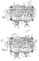
- FIG. 1 illustrates a front perspective interior view of a two-stage cooling system 10 according to an embodiment of the present invention.
- the cooling system 10 includes a cabinet 12, which may be formed of polycarbonate, that includes a base 14 integrally formed with lateral walls 16, and a rear wall 18.
- the lateral walls 16 and rear wall 18 are, in turn, integrally formed with an upper wall 20.
- the base 14, the lateral walls 16, the rear wall 18, and the upper wall 20 define a venting chamber 22 therebetween.
- a removable front cover (not shown in FIG. 1 ) is secured to edges of the base 14, lateral walls 16, and upper wall 20 to enclose the venting chamber 22.
- a gas inlet passage 24 is formed through one of the lateral walls 16.
- the gas inlet passage 24 is configured to receive and retain a gas delivery tube, pipe, duct, or the like 26 of a gas (such as air) compression system (not shown in FIG. 1 ).
- the gas inlet passage 24 may securely retain the gas delivery pipe 26 through a threadable or compression type connection.
- the gas inlet passage 24 is connected to the first and second main heat conduction housings 28 and 29, described below.
- venting hole 27 is formed through the rear wall 18.
- the venting hole 27 allows gas, such as air, within the venting chamber 22 to pass out of the cooling system 10.
- a first cylindrical main heat conduction housing 28 may be securely retained within a hole (not shown) formed in the base 14 through a variety of connections.
- the first cylindrical main housing 28 may be threadably secured within the hole, or the first cylindrical main housing 28 may be bonded to the base 14.
- the first main heat conduction housing 28 extends into the venting chamber 22 and supports a first vortex tube 30 that includes a first hot tube, pipe, duct or the like 32, and first cool gas delivery pipe 40 extending through the base 14 of the cabinet 12.
- the first main heat conduction housing 28 also supports two upwardly extending vent tubes, pipes, ducts, or the like 34 and 36.
- a first thermostat 38 and the first cool gas delivery pipe 40 extend from the first main heat conduction housing 28 through the base 14.
- the first hot pipe 32 may be one end of the first vortex tube 30, while the first cool gas delivery pipe 40 may be the opposite end of the first vortex tube 30.
- a second cylindrical main heat conduction housing 29 may be securely retained within a hole (not shown) formed in the base 14 through a variety of connections.
- the second cylindrical main housing 29 may be threadably secured within the hole, or the second cylindrical main housing 29 may be bonded to the base 14.
- the second main heat conduction housing 29 extends into the venting chamber 22 and supports a second vortex tube 31 that includes a second hot tube, pipe, duct or the like 33, and second cool gas delivery pipe 41 extending through the base 14 of the cabinet 12.
- the second main heat conduction housing 29 also supports two upwardly extending vent tubes, pipes, ducts, or the like 35 and 37.
- a second thermostat 39 and the second cool gas delivery pipe 41 extend from the second main heat conduction housing 29 through the base 14.
- the second hot pipe 33 may be one end of the second vortex tube 31, while the second cool gas delivery pipe 41 may be the opposite end of the second vortex tube 31.
- the first cylindrical main heat conduction housing 28 is connected to the second cylindrical main heat conduction housing 29 with compressed air piping 95; the compressed air inlet piping 95 is in fluid communication with the gas inlet passage 24.
- the first and second main heat conduction housings 28 and 29 are each operable to produce cool gas, such as air, that is delivered out of the cooling system 10 via the first and second cool gas delivery pipes 40 and 41, respectively.
- the first and second thermostats 38 and 39 are each configured to detect temperatures within an enclosure (not shown).
- the first and second main heat conduction housings 28 and 29 operate to produce cool air based on temperature readings of the respective first and second thermostats 38 and 39 that is delivered through the respective first and second cool gas delivery pipes 40 and 41.
- first and second main heat conduction housings 28 and 29 are controlled by separate first and second thermostats 38 and 39, the first and second main heat conduction housings 28 and 29 can be adjusted so that only the first main heat conduction housing 28 operates when the heat load, or temperature in the enclosure, is low. If or when the heat load rises, the second main heat conduction housing 29 is activated. Alternatively, the first and second main heat conduction housings 28 and 29 can be adjusted so that only the second main heat conduction housing 29 operates when the heat load is low, and the first main heat conduction housing 28 can be activated when the heat load rises.
- This two-stage cooling system 10 allows for reduced compressed air consumption during periods of low heat load. The following scenario is an example of how the two-stage cooling system 10 may operate:
- the two-stage cooling system 10 is particularly well-suited for cooling electrical enclosures. Whereas a single-stage cooling system may be capable of producing up to 2500 BTUH of cooling, the two-stage cooling system 10, with two cooling devices inside the main heat conduction housings 28 and 29, has a much greater cooling capacity of 5000 BTUH, for example.
- the first (and potentially second) main heat conduction housings 28 (and 29) also produce heated gas, such as air, within the venting chamber 22.
- heated gas such as air
- the heated gas is vented through the venting hole 27.
- a one-way check valve 96 when only the first stage of cooling is activated, it is possible that hot exhaust from the first-stage cooler, or first vortex tube 30, may flow back through the hot exhaust of the second-stage cooler, or second vortex tube 31, and into the enclosure, thereby reducing or defeating the cooling effect of the first-stage cooler, or first vortex tube 30.
- the one-way check valve 96 at the hot end of the second-stage vortex tube 31 prevents such backflow.
- FIG. 2 illustrates the two-stage cooling system 10 with two one-way check valves 96 at the hot end of the second-stage vortex tube 31.
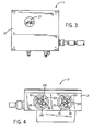
- FIG. 3 illustrates a rear perspective view of the two-stage cooling system 10.
- the venting hole 27 provides a passage for gas within the venting chamber 22 (shown in FIG. 1 ) to pass out of the cooling system 10.
- FIG. 4 illustrates a bottom perspective view of the two-stage cooling system 10.
- the first and second main heat conduction housings 28 and 29 are secured within the base 14.
- the first and second thermostats 38 and 39 and the first and second cool gas delivery pipes 40 and 41 of the respective first and second vortex tubes 30 and 31 extend downwardly from the main heat conduction housings 28 and 29.
- a vent hole 100 is formed through the first main heat conduction housing 28 and is in fluid communication with the vent pipe 34 (shown in FIG. 1 ).
- a vent hole 101 is formed through the second main heat conduction housing 29 and is in fluid communication with the vent pipe 35 (shown in FIG. 1 ).
- a vent hole 102 is also formed through the first main conduction housing 28 and is in fluid communication with the vent pipe 36 (shown in FIG. 1 ).
- a vent hole 103 is also formed through the second main conduction housing 29 and is in fluid communication with the vent pipe 37 (shown in FIG. 1 ).
- the vent holes 100 and 102 allow gas, such as air, to pass into the vent pipes 34 and 36, into the hot area of the venting chamber 22 (shown in FIG. 1 ), and eventually out of the cooling system 10 via the venting hole 27 (shown in FIGS. 1 and 2 ).
- the vent holes 101 and 103 also allow gas, such as air, to pass into the vent pipes 35 and 37, into the hot area of the venting chamber 22, and eventually out of the cooling system 10 via the venting hole 27.
- a first bleed air hole 104 may also be formed through the first main heat conduction housing 28 and is configured to allow gas to pass from the first main heat conduction housing 28 out of the cooling system 10 into an enclosure.
- a second bleed air hole 105 may also be formed through the second main heat conduction housing 29 and is configured to allow gas to pass from the second main heat conduction housing 29 out of the cooling system 10 into the enclosure.
- the bleed air holes 104 and 105 may be used to maintain a pressure differential between an interior of an enclosure and its outside environment to keep the enclosure interior clean.
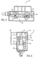
- FIG. 5 illustrates a top perspective interior view of the two-stage cooling system 10 in which a porous plastic tube 50 is connected to an outlet of the hot end of the first vortex tube 30 and an outlet of the hot end of the second vortex tube 31.
- the porous plastic tube 50 may be secured within the venting chamber 22.
- the hot exhaust air expelled from each vortex tube 30 and 31 can be routed through a common porous plastic tube muffler 50 or the exhaust can be routed through separate mufflers 50. Because the tubing 50 is porous, hot exhaust gases may pass therethrough and out of the vent opening 27.
- FIG. 6 illustrates a side perspective interior view of the two-stage cooling system 10 in which a first dampening sleeve 42 is disposed over the first hot pipe 32.
- a second dampening sleeve 43 is similarly disposed over the second hot pipe 33.
- the hot pipes 32 and 33 of the vortex tubes 30 and 31, respectively, are enclosed inside of the respective dampening sleeves 42 and 43, which may be an elastomeric or rubber hose that surrounds a substantial portion of the respective hot pipes 32 and 33.
- the dampening sleeves 42 and 43 may reduce noise produced within and/or by the vortex tubes 30 and 31 by dampening high frequency vibrations and resulting noise from the hot pipes 32 and 33. In any event, it has been found that disposing the dampening sleeves 42 and 43 around the hot pipes 32 and 33 dampens, or otherwise reduces, the amount of noise produced by the vortex tubes 30 and 31.
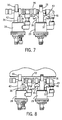
- FIG. 7 illustrates a front perspective view of the two vortex cooling devices 30 and 31 connected through compressed air piping 95, with the remainder of the system removed for clarity.
- a hollow, flexible, open-ended tube 44 is secured to the vent pipe 35
- a hollow, flexible, open-ended tube 46 is secured to the vent pipe 37.
- the tubes 44 and 46 may be vinyl tubes. Gas from the vent pipes 35 and 37 is passed into the tubes 44 and 46, respectively, and out into the cool area of the venting chamber 22 through the open ends of the tubes 44 and 46.
- similar hollow, flexible, open-ended tubes may be secured to the vent pipes 34 and/or 36.
- a baffle 52 may be disposed within the cabinet 12 to segregate the venting chamber 22 into a hot exhaust portion and a cool exhaust portion.
- FIG. 8 illustrates a suitable positioning of the baffle 52 with respect to the two vortex cooling devices 30 and 31.
- FIG. 9 illustrates a suitable arrangement of the baffle 52 between the porous plastic tube muffler 50 and the two vortex cooling devices 30 and 31. As further illustrated in FIG. 6 , this arrangement allows the venting hole 27 to be divided into a hot exhaust portion and a cool exhaust portion.
- the baffle 52 may be plastic, rubber, vinyl, or the like, and serves to segregate the venting chamber 22 into two separate areas--a hot exhaust area 54 and a cool air exhaust area 56. As such, hot and cool gases within the venting chamber 22 are separated from one another.
- the baffle 52 ensures that hot and cool air flows within the venting chamber 22 are separate from one another so that the pressure created by the hot exhaust gas does not overpower the vented cool air.
- FIG. 10 illustrates the two vortex cooling devices 30 and 31 in place inside the cabinet 12.
- An open cell foam sheet 60 lines the rear wall 1 of the cabinet 12 within the venting chamber 22. Additionally, open cell foam may also line the base 14, lateral walls 16, and upper wall 20 of the cabinet 12 within the venting chamber 22. Further, sheets of open cell foam may also line an interior surface of a cover (not shown) of the cabinet 12. The open cell foam sheet 60, and any other cell foam within the venting cabinet 22, further dampens noise produced by the cooling system 10, while also allowing exhaust gas to flow through.
- open cell foam sheets may line outer surfaces of the cabinet 12 in addition to, or in lieu of, interior surfaces of the cabinet 12 within the venting chamber 22.
- the sheet 60 may be another dampening material, such as rubber, plastic, or the like.
- a shroud 64 is mounted over the outside of the rear wall 18 and may cover a substantial portion of the rear wall 18.
- An exhaust path is defined between an interior of the shroud 64 and an outer surface of the rear wall 18.
- exhaust gases may pass out of the venting chamber 22 through the venting hole 27.
- the exhaust gases are then directed by the shroud 64 through an exhaust outlet 68 at the bottom of the shroud 64.
- relatively cooler exhaust gases that pass from the vent pipes 35 and 37 out through the flexible tubes 44 and 46, respectively, may pass through the venting hole 27 and out of the cooling system 10 through the exhaust outlet 68.
- hot exhaust gas that passes from the hot pipes 32 and 33 through the porous plastic tubing 50 may pass through the pores of the plastic tubing 50, and out of the cooling system 10 through the venting hole 27. The hot exhaust gas may then pass out of the cooling system 10 through the exhaust outlet 68.
- FIG. 12 illustrates an internal view of the shroud 64.
- the shroud 64 includes lateral walls 106 having mounting flanges or edges 108, a top wall 110, having a mounting flange or edge 112, and a cover 114.
- the lateral walls 106, the top wall 110, and the cover 114 define an exhaust chamber 116.
- the shroud 64 is configured to mount to the rear of the cabinet 12 (shown, for example, in FIGS. 6 and 11 ). For example, the shroud 64 is mounted so that mounting flanges 108 and 112 abut the rear wall of the cabinet 12.
- a series of baffles 118 are positioned within the exhaust chamber 116.
- An exhaust outlet 68 is formed through the lower portion of the shroud 64, proximate a lower baffle 118.
- the baffles 118 are configured to prevent moisture from infiltrating the shroud 64. While four baffles 118 are shown, more or less baffles than those shown may be used with the shroud 64.
- FIG. 13 illustrates a front perspective view of the two-stage cooling system 10 connected to a compressed gas filter 70.
- the compressed gas filter 70 filters compressed gas, such as air, to the main heat conduction housings 28 and 29 through a delivery pipe 72.
- delivery pipe 72 is sealingly secured to a corresponding inlet pipe 74 that connects to the main heat conduction housings 28 and 29.
- the delivery pipe 72 and the inlet pipe 74 may be sealingly secured to one another, through, for example, a sealed threadable interface, proximate the gas inlet passage 24.
- compressed gas such as air
- compressed gas may pass from the gas filter 70, through the delivery pipe 72 and into the inlet pipe 74, which, in turn provides a fluid path through the compressed air piping 95 and into the main heat conduction housings 28 and 29.
- the compressed gas passes into the vortex tubes 30 and/or 31, when the thermostats 38 and/or 39 call for cooling, including the hot pipes 32 and 33 and the cool gas delivery pipes 40 and 41, thereby producing cool gas that is passed through the cool gas delivery pipes 40 and 41.
- the two-stage cooling system 10 may produce cooled gas through compressed air being supplied to the vortex tube or vortex tubes.
- the inlet pipe 74 which delivers compressed air into the cooling system 10, is within the cool exhaust portion of the cabinet 12 to ensure that the hot exhaust air from the pipe 50 is not in close proximity to the compressed air being delivered to the cooling system 10 through the inlet pipe 74.
- FIG. 14 illustrates a front perspective interior view of the cooling system with a plurality of flexible dampening members 76.
- the flexible dampening members 76 may be flexible open cell foam rods. Each rod may have a diameter of approximately two inches. As shown in FIG. 14 , two flexible dampening members 76 are folded and compressed into the hot exhaust area 54 of the venting chamber 22, while more dampening members 76 are folded and compressed into the cool air area 56. Additional dampening members 76 may be positioned within the venting chamber 22. Overall, the open cell foam, whether in the form of flexible rod-like dampening members 76, or sheets (such as open cell foam sheet 60 shown in FIG. 10 ) may occupy a substantial portion of the venting chamber 22.
- open cell foam may occupy approximately 90% of the space within the venting chamber 22.
- the dampening members 76 provide additional noise damping within the cooling system 10, while at the same time, allowing exhaust gas to flow therethrough.
- the dampening members 76 may be formed of porous rubber, plastic, or the like.
- FIGS. 15 and 16 illustrate a front elevational view and a lateral elevational view, respectively, of the two-stage cooling system 10 connected to an enclosure 80.
- the cabinet 12 mounts to the top of the enclosure 80 such that the base 14 is supported by a top surface 82 of the enclosure 80.
- Two knockout holes 84 and 85 are formed through the top surface 82 of the enclosure 80, and a lower portion of each of the main heat conduction housings 28 and 29 is sealingly secured within the respective knockout hole 84 and 85.
- the thermostats 38 and 39 and the cool gas delivery pipes 40 and 41 extend into an interior chamber 86 of the enclosure 80.
- the vent holes 100, 101, 102, and 103 (shown in FIG. 4 ), and the bleed air holes 104 and 105 are also exposed to the interior chamber 86.
- Gas such as air
- the main heat conduction housings 28 and 29 then produce cool gas through the vortex tubes (which include the hot pipes and the cool gas delivery pipes).
- a distal end of each of the cool gas delivery pipes 40 and 41 is connected to one end of a flexible tube 88 and 89 which provides a fluid path from the cool gas delivery pipe 40 and 41 to a muffler 90 and 91, respectively.
- Sealed tubes 92 and 93 (which may also be a vinyl tube) having a plurality of passages 94 and 95 are connected to an opposite end of the respective muffler 90 and 91.
- cool gas may be delivered to the sealed tubes 92 and 93 through the path defined from the cool gas delivery pipes 40 and 41, the flexible tubes 88 and 89, and the mufflers 90 and 91.
- the cool gas then passes into the interior chamber 86 of the enclosure 80 to cool internal components.
- the gas may then be vented back into the cooling system 10 through the vent holes 100, 101, 102, and 103 (shown in FIG. 4 ), and out of the cooling system 10, as described above.
- exhaust and vented gases pass out of the cooling system 10 through the exhaust outlet 68 located at a lower end of the shroud 64.
- the sealed tubes 92 and 93 may be open-ended tubes without passages formed therethrough. In this case, the cold gas may pass through the open end of each tube.
- a cover 62 is secured over a front of the cabinet 12.
- the dampening sleeves 42 and 43 positioned around the hot pipes 32 and 33, the porous plastic tube 50, the dampening sheets 60, dampening members 76 and cold air mufflers 90 and 91 all serve to dampen, diminish, absorb, or otherwise reduce noise created by the operation of the vortex tubes 30 and 31 (including the hot pipes 32 and 33).
- the two-stage cooling system 10 produces less noise than many prior vortex tube cooling devices.
- the two-stage cooling system 10 is also capable of continually pressurizing and purging the enclosure 80, even when the vortex tubes 30 and 31 are deactivated.
- One benefit that the compressed air driven vortex tube cooling system 10 has over conventional "Freon type" air conditioners is that the cooling system 10 blows the cooling air into the enclosure 80 under a slight positive pressure.
- the pressure within the enclosure 80 is slightly higher than the air pressure outside of the enclosure 80.
- the pressure differential between the outside of the enclosure 80 and the interior of the enclosure 80 serves to ensure that contaminants do not infiltrate into the enclosure 80.
- a source of compressed air (such as that supplied through the compressed gas filter 70) is connected to the bleed air holes 104 and 105 formed through the bottoms of the main heat conduction housings 28 and 29.
- the bleed air holes 104 and 105 are in fluid communication with the compressed gas supply port.
- the ends of the bleed air holes 104 and 105 may each threadably retain a removable set screw to plug the hole if pressurization of the enclosure 80 is not desired.
- the bleed air holes 104 and 105 may be in fluid communication with a compressed air supply, thereby allowing air to be continually blown into the enclosure 80, without operation of the main heat conduction housings 28 and 29.
- the enclosure 80 may remain clean even when the vortex tubes 30 and 31 are not operating.
- embodiments of the present invention provide a compact cooling system that is easy to install, has substantial cooling capacity, and produces low noise levels.
- Embodiments of the present invention provide a cooling system that allows for reduced compressed air consumption during periods of low heat load. Additionally, embodiments of the present invention provide a vortex tube cooling system that may maintain a clean enclosure interior through air pressure differentials even when the cooling system is not operating in a cooling mode.
Landscapes
- Engineering & Computer Science (AREA)
- Physics & Mathematics (AREA)
- Mechanical Engineering (AREA)
- Thermal Sciences (AREA)
- General Engineering & Computer Science (AREA)
- Cooling Or The Like Of Electrical Apparatus (AREA)
- Heat-Exchange Devices With Radiators And Conduit Assemblies (AREA)
- Pipe Accessories (AREA)
Applications Claiming Priority (3)
| Application Number | Priority Date | Filing Date | Title |
|---|---|---|---|
| US3852808P | 2008-03-21 | 2008-03-21 | |
| US12/407,759 US8402773B2 (en) | 2008-03-21 | 2009-03-19 | Two-stage cooling system |
| EP09723056.9A EP2276982B1 (en) | 2008-03-21 | 2009-03-20 | Two-stage cooling system |
Related Parent Applications (2)
| Application Number | Title | Priority Date | Filing Date |
|---|---|---|---|
| EP09723056.9 Division | 2009-03-20 | ||
| EP09723056.9A Division-Into EP2276982B1 (en) | 2008-03-21 | 2009-03-20 | Two-stage cooling system |
Publications (2)
| Publication Number | Publication Date |
|---|---|
| EP2363666A1 EP2363666A1 (en) | 2011-09-07 |
| EP2363666B1 true EP2363666B1 (en) | 2013-06-05 |
Family
ID=41087545
Family Applications (2)
| Application Number | Title | Priority Date | Filing Date |
|---|---|---|---|
| EP11165731.8A Active EP2363666B1 (en) | 2008-03-21 | 2009-03-20 | Two-stage cooling system |
| EP09723056.9A Active EP2276982B1 (en) | 2008-03-21 | 2009-03-20 | Two-stage cooling system |
Family Applications After (1)
| Application Number | Title | Priority Date | Filing Date |
|---|---|---|---|
| EP09723056.9A Active EP2276982B1 (en) | 2008-03-21 | 2009-03-20 | Two-stage cooling system |
Country Status (4)
| Country | Link |
|---|---|
| US (1) | US8402773B2 (enExample) |
| EP (2) | EP2363666B1 (enExample) |
| JP (1) | JP5580286B2 (enExample) |
| WO (1) | WO2009117636A2 (enExample) |
Families Citing this family (10)
| Publication number | Priority date | Publication date | Assignee | Title |
|---|---|---|---|---|
| US8716981B2 (en) * | 2011-11-11 | 2014-05-06 | Lg Chem, Ltd. | System and method for cooling and cycling a battery pack |
| US9593862B2 (en) * | 2013-08-06 | 2017-03-14 | General Electric Company | Air disruption system for an enclosure |
| JP6053709B2 (ja) * | 2014-02-27 | 2016-12-27 | 三菱電機ビルテクノサービス株式会社 | エレベータシステム |
| EP3169945A1 (en) | 2014-07-15 | 2017-05-24 | Tofas Turk Otomobil Fabrikasi Anonim Sirketi | Cascade cold water generation system and method |
| KR20170098545A (ko) * | 2016-02-22 | 2017-08-30 | 엘에스산전 주식회사 | 전력변환장치용 냉각 장치 |
| US10427538B2 (en) | 2017-04-05 | 2019-10-01 | Ford Global Technologies, Llc | Vehicle thermal management system with vortex tube |
| US10358046B2 (en) | 2017-04-05 | 2019-07-23 | Ford Global Technologies, Llc | Vehicle thermal management system with vortex tube |
| CN110486978B (zh) * | 2019-08-29 | 2021-08-24 | 上海理工大学 | 阵列圆柱群型多级叠层微通道节流换热制冷器 |
| CN110486979B (zh) * | 2019-08-29 | 2021-08-24 | 上海理工大学 | 多级单侧预冷的叠层交错微通道节流换热制冷器 |
| DE102023205419A1 (de) * | 2023-06-12 | 2024-12-12 | Siemens Aktiengesellschaft | Kühlsystem für eine elektrische Schaltanlage |
Family Cites Families (15)
| Publication number | Priority date | Publication date | Assignee | Title |
|---|---|---|---|---|
| US2896849A (en) * | 1955-05-05 | 1959-07-28 | Argentieri Peter | Air conditioning apparatus having controlled volume and temperature air flow |
| US3654768A (en) * | 1970-06-16 | 1972-04-11 | Vortec Corp | Vortex tube cooling system |
| US4019986A (en) * | 1973-06-11 | 1977-04-26 | William Alan Burris | Portable water purifier |
| JPS60200057A (ja) * | 1984-03-23 | 1985-10-09 | 株式会社ジヤンテツク | 冷凍サイクル装置 |
| US5010736A (en) | 1990-04-16 | 1991-04-30 | Vortec Corporation | Cooling system for enclosures |
| JPH05231733A (ja) * | 1991-12-25 | 1993-09-07 | Naoji Isshiki | 脈動流ボルテックスチューブ冷凍機 |
| US5335854A (en) * | 1992-12-11 | 1994-08-09 | Ransburg Corporation | Electrically insulated pressure feed paint reservoir |
| JPH08233383A (ja) * | 1995-02-28 | 1996-09-13 | Hisamoto Suzuki | 冷却装置 |
| JPH08316673A (ja) * | 1995-05-17 | 1996-11-29 | Fujitsu Ltd | 冷却構造 |
| JPH10141792A (ja) * | 1996-11-13 | 1998-05-29 | Daikin Ind Ltd | ボルテックス管冷凍機 |
| US5987696A (en) * | 1996-12-24 | 1999-11-23 | Wang; Kevin W. | Carpet cleaning machine |
| US6868938B2 (en) * | 2001-09-07 | 2005-03-22 | Bombardier Recreational Products Inc. | Noise-reducing engine enclosure |
| US6990817B1 (en) | 2003-12-16 | 2006-01-31 | Sun Microsystems, Inc. | Method and apparatus for cooling electronic equipment within an enclosure |
| US7461513B2 (en) | 2006-03-08 | 2008-12-09 | Illinois Tool Works Inc. | Cooling system |
| US7751188B1 (en) * | 2007-06-29 | 2010-07-06 | Emc Corporation | Method and system for providing cooling of components in a data storage system |
-
2009
- 2009-03-19 US US12/407,759 patent/US8402773B2/en active Active
- 2009-03-20 WO PCT/US2009/037765 patent/WO2009117636A2/en not_active Ceased
- 2009-03-20 EP EP11165731.8A patent/EP2363666B1/en active Active
- 2009-03-20 JP JP2011500971A patent/JP5580286B2/ja active Active
- 2009-03-20 EP EP09723056.9A patent/EP2276982B1/en active Active
Also Published As
| Publication number | Publication date |
|---|---|
| EP2363666A1 (en) | 2011-09-07 |
| JP2011515645A (ja) | 2011-05-19 |
| EP2276982A2 (en) | 2011-01-26 |
| EP2276982B1 (en) | 2014-09-03 |
| WO2009117636A3 (en) | 2009-12-10 |
| US20090235672A1 (en) | 2009-09-24 |
| WO2009117636A2 (en) | 2009-09-24 |
| JP5580286B2 (ja) | 2014-08-27 |
| US8402773B2 (en) | 2013-03-26 |
Similar Documents
| Publication | Publication Date | Title |
|---|---|---|
| EP2363666B1 (en) | Two-stage cooling system | |
| CN212987397U (zh) | 厨房空气调节系统 | |
| CN1329638C (zh) | 压缩机围罩 | |
| EP1266548A2 (en) | Method and apparatus for cooling electronic enclosures | |
| JPH08506405A (ja) | 油圧装置 | |
| CN101876464A (zh) | 窗式空调器 | |
| AU2008291678A1 (en) | Improvements in air intakes for water heaters | |
| JP2011515645A5 (enExample) | ||
| US7658183B1 (en) | Engine air intake and fuel chilling system and method | |
| US11661941B2 (en) | Sound control for a heating, ventilation, and air conditioning unit | |
| US7461513B2 (en) | Cooling system | |
| JP5838295B2 (ja) | ヒートポンプ温水暖房装置 | |
| CN102400887B (zh) | 低温泵及过滤器装置 | |
| JP4580878B2 (ja) | 空気圧装置ステーション及び空気圧装置の収納ボックス | |
| CN212457165U (zh) | 顶部嵌入式空气调节设备 | |
| JP5119558B2 (ja) | 空気圧装置ステーション及び空気圧装置の収納ボックス | |
| CN114060931A (zh) | 顶部嵌入式空气调节设备 | |
| KR100469783B1 (ko) | 에어컨의 산소 공급 장치 | |
| CN220424944U (zh) | 一种制氧机 | |
| KR100768159B1 (ko) | 패키지 에어컨에서 송풍팬 모터의 방진구조 | |
| CN212106383U (zh) | 一种气泵降噪装置 | |
| KR102892914B1 (ko) | 차량용 무시동 냉난방 장치 | |
| CN217004736U (zh) | 厨房空气调节系统 | |
| CN221122567U (zh) | 制冷系统和冰箱 | |
| CN217182729U (zh) | 远程控制柜和分散控制系统 |
Legal Events
| Date | Code | Title | Description |
|---|---|---|---|
| PUAI | Public reference made under article 153(3) epc to a published international application that has entered the european phase |
Free format text: ORIGINAL CODE: 0009012 |
|
| AC | Divisional application: reference to earlier application |
Ref document number: 2276982 Country of ref document: EP Kind code of ref document: P |
|
| AK | Designated contracting states |
Kind code of ref document: A1 Designated state(s): AT BE BG CH CY CZ DE DK EE ES FI FR GB GR HR HU IE IS IT LI LT LU LV MC MK MT NL NO PL PT RO SE SI SK TR |
|
| 17P | Request for examination filed |
Effective date: 20120307 |
|
| GRAP | Despatch of communication of intention to grant a patent |
Free format text: ORIGINAL CODE: EPIDOSNIGR1 |
|
| GRAS | Grant fee paid |
Free format text: ORIGINAL CODE: EPIDOSNIGR3 |
|
| GRAA | (expected) grant |
Free format text: ORIGINAL CODE: 0009210 |
|
| AC | Divisional application: reference to earlier application |
Ref document number: 2276982 Country of ref document: EP Kind code of ref document: P |
|
| AK | Designated contracting states |
Kind code of ref document: B1 Designated state(s): AT BE BG CH CY CZ DE DK EE ES FI FR GB GR HR HU IE IS IT LI LT LU LV MC MK MT NL NO PL PT RO SE SI SK TR |
|
| REG | Reference to a national code |
Ref country code: GB Ref legal event code: FG4D |
|
| REG | Reference to a national code |
Ref country code: CH Ref legal event code: EP |
|
| REG | Reference to a national code |
Ref country code: AT Ref legal event code: REF Ref document number: 615892 Country of ref document: AT Kind code of ref document: T Effective date: 20130615 |
|
| REG | Reference to a national code |
Ref country code: IE Ref legal event code: FG4D |
|
| REG | Reference to a national code |
Ref country code: DE Ref legal event code: R096 Ref document number: 602009016330 Country of ref document: DE Effective date: 20130801 |
|
| REG | Reference to a national code |
Ref country code: AT Ref legal event code: MK05 Ref document number: 615892 Country of ref document: AT Kind code of ref document: T Effective date: 20130605 |
|
| PG25 | Lapsed in a contracting state [announced via postgrant information from national office to epo] |
Ref country code: NO Free format text: LAPSE BECAUSE OF FAILURE TO SUBMIT A TRANSLATION OF THE DESCRIPTION OR TO PAY THE FEE WITHIN THE PRESCRIBED TIME-LIMIT Effective date: 20130905 Ref country code: SE Free format text: LAPSE BECAUSE OF FAILURE TO SUBMIT A TRANSLATION OF THE DESCRIPTION OR TO PAY THE FEE WITHIN THE PRESCRIBED TIME-LIMIT Effective date: 20130605 Ref country code: SI Free format text: LAPSE BECAUSE OF FAILURE TO SUBMIT A TRANSLATION OF THE DESCRIPTION OR TO PAY THE FEE WITHIN THE PRESCRIBED TIME-LIMIT Effective date: 20130605 Ref country code: AT Free format text: LAPSE BECAUSE OF FAILURE TO SUBMIT A TRANSLATION OF THE DESCRIPTION OR TO PAY THE FEE WITHIN THE PRESCRIBED TIME-LIMIT Effective date: 20130605 Ref country code: ES Free format text: LAPSE BECAUSE OF FAILURE TO SUBMIT A TRANSLATION OF THE DESCRIPTION OR TO PAY THE FEE WITHIN THE PRESCRIBED TIME-LIMIT Effective date: 20130916 Ref country code: FI Free format text: LAPSE BECAUSE OF FAILURE TO SUBMIT A TRANSLATION OF THE DESCRIPTION OR TO PAY THE FEE WITHIN THE PRESCRIBED TIME-LIMIT Effective date: 20130605 Ref country code: GR Free format text: LAPSE BECAUSE OF FAILURE TO SUBMIT A TRANSLATION OF THE DESCRIPTION OR TO PAY THE FEE WITHIN THE PRESCRIBED TIME-LIMIT Effective date: 20130906 Ref country code: LT Free format text: LAPSE BECAUSE OF FAILURE TO SUBMIT A TRANSLATION OF THE DESCRIPTION OR TO PAY THE FEE WITHIN THE PRESCRIBED TIME-LIMIT Effective date: 20130605 |
|
| REG | Reference to a national code |
Ref country code: NL Ref legal event code: VDEP Effective date: 20130605 |
|
| REG | Reference to a national code |
Ref country code: LT Ref legal event code: MG4D |
|
| PG25 | Lapsed in a contracting state [announced via postgrant information from national office to epo] |
Ref country code: HR Free format text: LAPSE BECAUSE OF FAILURE TO SUBMIT A TRANSLATION OF THE DESCRIPTION OR TO PAY THE FEE WITHIN THE PRESCRIBED TIME-LIMIT Effective date: 20130605 Ref country code: BG Free format text: LAPSE BECAUSE OF FAILURE TO SUBMIT A TRANSLATION OF THE DESCRIPTION OR TO PAY THE FEE WITHIN THE PRESCRIBED TIME-LIMIT Effective date: 20130905 |
|
| PG25 | Lapsed in a contracting state [announced via postgrant information from national office to epo] |
Ref country code: LV Free format text: LAPSE BECAUSE OF FAILURE TO SUBMIT A TRANSLATION OF THE DESCRIPTION OR TO PAY THE FEE WITHIN THE PRESCRIBED TIME-LIMIT Effective date: 20130605 |
|
| PG25 | Lapsed in a contracting state [announced via postgrant information from national office to epo] |
Ref country code: BE Free format text: LAPSE BECAUSE OF FAILURE TO SUBMIT A TRANSLATION OF THE DESCRIPTION OR TO PAY THE FEE WITHIN THE PRESCRIBED TIME-LIMIT Effective date: 20130605 Ref country code: PT Free format text: LAPSE BECAUSE OF FAILURE TO SUBMIT A TRANSLATION OF THE DESCRIPTION OR TO PAY THE FEE WITHIN THE PRESCRIBED TIME-LIMIT Effective date: 20131007 Ref country code: IS Free format text: LAPSE BECAUSE OF FAILURE TO SUBMIT A TRANSLATION OF THE DESCRIPTION OR TO PAY THE FEE WITHIN THE PRESCRIBED TIME-LIMIT Effective date: 20131005 Ref country code: SK Free format text: LAPSE BECAUSE OF FAILURE TO SUBMIT A TRANSLATION OF THE DESCRIPTION OR TO PAY THE FEE WITHIN THE PRESCRIBED TIME-LIMIT Effective date: 20130605 Ref country code: CZ Free format text: LAPSE BECAUSE OF FAILURE TO SUBMIT A TRANSLATION OF THE DESCRIPTION OR TO PAY THE FEE WITHIN THE PRESCRIBED TIME-LIMIT Effective date: 20130605 Ref country code: EE Free format text: LAPSE BECAUSE OF FAILURE TO SUBMIT A TRANSLATION OF THE DESCRIPTION OR TO PAY THE FEE WITHIN THE PRESCRIBED TIME-LIMIT Effective date: 20130605 |
|
| PG25 | Lapsed in a contracting state [announced via postgrant information from national office to epo] |
Ref country code: RO Free format text: LAPSE BECAUSE OF FAILURE TO SUBMIT A TRANSLATION OF THE DESCRIPTION OR TO PAY THE FEE WITHIN THE PRESCRIBED TIME-LIMIT Effective date: 20130605 Ref country code: NL Free format text: LAPSE BECAUSE OF FAILURE TO SUBMIT A TRANSLATION OF THE DESCRIPTION OR TO PAY THE FEE WITHIN THE PRESCRIBED TIME-LIMIT Effective date: 20130605 Ref country code: PL Free format text: LAPSE BECAUSE OF FAILURE TO SUBMIT A TRANSLATION OF THE DESCRIPTION OR TO PAY THE FEE WITHIN THE PRESCRIBED TIME-LIMIT Effective date: 20130605 |
|
| PLBE | No opposition filed within time limit |
Free format text: ORIGINAL CODE: 0009261 |
|
| STAA | Information on the status of an ep patent application or granted ep patent |
Free format text: STATUS: NO OPPOSITION FILED WITHIN TIME LIMIT |
|
| RAP2 | Party data changed (patent owner data changed or rights of a patent transferred) |
Owner name: ILLINOIS TOOL WORKS INC. |
|
| PG25 | Lapsed in a contracting state [announced via postgrant information from national office to epo] |
Ref country code: DK Free format text: LAPSE BECAUSE OF FAILURE TO SUBMIT A TRANSLATION OF THE DESCRIPTION OR TO PAY THE FEE WITHIN THE PRESCRIBED TIME-LIMIT Effective date: 20130605 |
|
| 26N | No opposition filed |
Effective date: 20140306 |
|
| PG25 | Lapsed in a contracting state [announced via postgrant information from national office to epo] |
Ref country code: IT Free format text: LAPSE BECAUSE OF FAILURE TO SUBMIT A TRANSLATION OF THE DESCRIPTION OR TO PAY THE FEE WITHIN THE PRESCRIBED TIME-LIMIT Effective date: 20130605 |
|
| REG | Reference to a national code |
Ref country code: DE Ref legal event code: R097 Ref document number: 602009016330 Country of ref document: DE Effective date: 20140306 |
|
| PG25 | Lapsed in a contracting state [announced via postgrant information from national office to epo] |
Ref country code: LU Free format text: LAPSE BECAUSE OF FAILURE TO SUBMIT A TRANSLATION OF THE DESCRIPTION OR TO PAY THE FEE WITHIN THE PRESCRIBED TIME-LIMIT Effective date: 20140320 |
|
| REG | Reference to a national code |
Ref country code: CH Ref legal event code: PL |
|
| GBPC | Gb: european patent ceased through non-payment of renewal fee |
Effective date: 20140320 |
|
| REG | Reference to a national code |
Ref country code: FR Ref legal event code: ST Effective date: 20141128 |
|
| REG | Reference to a national code |
Ref country code: IE Ref legal event code: MM4A |
|
| PG25 | Lapsed in a contracting state [announced via postgrant information from national office to epo] |
Ref country code: CH Free format text: LAPSE BECAUSE OF NON-PAYMENT OF DUE FEES Effective date: 20140331 Ref country code: FR Free format text: LAPSE BECAUSE OF NON-PAYMENT OF DUE FEES Effective date: 20140331 Ref country code: GB Free format text: LAPSE BECAUSE OF NON-PAYMENT OF DUE FEES Effective date: 20140320 Ref country code: IE Free format text: LAPSE BECAUSE OF NON-PAYMENT OF DUE FEES Effective date: 20140320 Ref country code: LI Free format text: LAPSE BECAUSE OF NON-PAYMENT OF DUE FEES Effective date: 20140331 |
|
| PG25 | Lapsed in a contracting state [announced via postgrant information from national office to epo] |
Ref country code: MT Free format text: LAPSE BECAUSE OF FAILURE TO SUBMIT A TRANSLATION OF THE DESCRIPTION OR TO PAY THE FEE WITHIN THE PRESCRIBED TIME-LIMIT Effective date: 20130605 |
|
| PG25 | Lapsed in a contracting state [announced via postgrant information from national office to epo] |
Ref country code: MC Free format text: LAPSE BECAUSE OF FAILURE TO SUBMIT A TRANSLATION OF THE DESCRIPTION OR TO PAY THE FEE WITHIN THE PRESCRIBED TIME-LIMIT Effective date: 20130605 |
|
| PG25 | Lapsed in a contracting state [announced via postgrant information from national office to epo] |
Ref country code: CY Free format text: LAPSE BECAUSE OF FAILURE TO SUBMIT A TRANSLATION OF THE DESCRIPTION OR TO PAY THE FEE WITHIN THE PRESCRIBED TIME-LIMIT Effective date: 20130605 |
|
| PG25 | Lapsed in a contracting state [announced via postgrant information from national office to epo] |
Ref country code: HU Free format text: LAPSE BECAUSE OF FAILURE TO SUBMIT A TRANSLATION OF THE DESCRIPTION OR TO PAY THE FEE WITHIN THE PRESCRIBED TIME-LIMIT; INVALID AB INITIO Effective date: 20090320 |
|
| PG25 | Lapsed in a contracting state [announced via postgrant information from national office to epo] |
Ref country code: MK Free format text: LAPSE BECAUSE OF FAILURE TO SUBMIT A TRANSLATION OF THE DESCRIPTION OR TO PAY THE FEE WITHIN THE PRESCRIBED TIME-LIMIT Effective date: 20130605 |
|
| P01 | Opt-out of the competence of the unified patent court (upc) registered |
Effective date: 20230606 |
|
| PGFP | Annual fee paid to national office [announced via postgrant information from national office to epo] |
Ref country code: DE Payment date: 20250327 Year of fee payment: 17 |
|
| PGFP | Annual fee paid to national office [announced via postgrant information from national office to epo] |
Ref country code: TR Payment date: 20250311 Year of fee payment: 17 |