EP2363301B1 - Stirnverzahnung für eine antreibbare Radnabe - Google Patents
Stirnverzahnung für eine antreibbare Radnabe Download PDFInfo
- Publication number
- EP2363301B1 EP2363301B1 EP11165259.0A EP11165259A EP2363301B1 EP 2363301 B1 EP2363301 B1 EP 2363301B1 EP 11165259 A EP11165259 A EP 11165259A EP 2363301 B1 EP2363301 B1 EP 2363301B1
- Authority
- EP
- European Patent Office
- Prior art keywords
- tooth
- toothing system
- spur toothing
- wheel hub
- teeth
- Prior art date
- Legal status (The legal status is an assumption and is not a legal conclusion. Google has not performed a legal analysis and makes no representation as to the accuracy of the status listed.)
- Revoked
Links
Images


Classifications
-
- B—PERFORMING OPERATIONS; TRANSPORTING
- B60—VEHICLES IN GENERAL
- B60B—VEHICLE WHEELS; CASTORS; AXLES FOR WHEELS OR CASTORS; INCREASING WHEEL ADHESION
- B60B27/00—Hubs
- B60B27/06—Hubs adapted to be fixed on axle
-
- F—MECHANICAL ENGINEERING; LIGHTING; HEATING; WEAPONS; BLASTING
- F16—ENGINEERING ELEMENTS AND UNITS; GENERAL MEASURES FOR PRODUCING AND MAINTAINING EFFECTIVE FUNCTIONING OF MACHINES OR INSTALLATIONS; THERMAL INSULATION IN GENERAL
- F16D—COUPLINGS FOR TRANSMITTING ROTATION; CLUTCHES; BRAKES
- F16D1/00—Couplings for rigidly connecting two coaxial shafts or other movable machine elements
- F16D1/06—Couplings for rigidly connecting two coaxial shafts or other movable machine elements for attachment of a member on a shaft or on a shaft-end
- F16D1/076—Couplings for rigidly connecting two coaxial shafts or other movable machine elements for attachment of a member on a shaft or on a shaft-end by clamping together two faces perpendicular to the axis of rotation, e.g. with bolted flanges
-
- B—PERFORMING OPERATIONS; TRANSPORTING
- B60—VEHICLES IN GENERAL
- B60B—VEHICLE WHEELS; CASTORS; AXLES FOR WHEELS OR CASTORS; INCREASING WHEEL ADHESION
- B60B27/00—Hubs
-
- B—PERFORMING OPERATIONS; TRANSPORTING
- B60—VEHICLES IN GENERAL
- B60B—VEHICLE WHEELS; CASTORS; AXLES FOR WHEELS OR CASTORS; INCREASING WHEEL ADHESION
- B60B27/00—Hubs
- B60B27/0005—Hubs with ball bearings
-
- B—PERFORMING OPERATIONS; TRANSPORTING
- B60—VEHICLES IN GENERAL
- B60B—VEHICLE WHEELS; CASTORS; AXLES FOR WHEELS OR CASTORS; INCREASING WHEEL ADHESION
- B60B27/00—Hubs
- B60B27/0015—Hubs for driven wheels
- B60B27/0021—Hubs for driven wheels characterised by torque transmission means from drive axle
- B60B27/0031—Hubs for driven wheels characterised by torque transmission means from drive axle of the axial type, e.g. front teeth
-
- B—PERFORMING OPERATIONS; TRANSPORTING
- B60—VEHICLES IN GENERAL
- B60B—VEHICLE WHEELS; CASTORS; AXLES FOR WHEELS OR CASTORS; INCREASING WHEEL ADHESION
- B60B27/00—Hubs
- B60B27/0078—Hubs characterised by the fixation of bearings
- B60B27/0084—Hubs characterised by the fixation of bearings caulking to fix inner race
-
- B—PERFORMING OPERATIONS; TRANSPORTING
- B60—VEHICLES IN GENERAL
- B60B—VEHICLE WHEELS; CASTORS; AXLES FOR WHEELS OR CASTORS; INCREASING WHEEL ADHESION
- B60B27/00—Hubs
- B60B27/0094—Hubs one or more of the bearing races are formed by the hub
-
- F—MECHANICAL ENGINEERING; LIGHTING; HEATING; WEAPONS; BLASTING
- F16—ENGINEERING ELEMENTS AND UNITS; GENERAL MEASURES FOR PRODUCING AND MAINTAINING EFFECTIVE FUNCTIONING OF MACHINES OR INSTALLATIONS; THERMAL INSULATION IN GENERAL
- F16C—SHAFTS; FLEXIBLE SHAFTS; ELEMENTS OR CRANKSHAFT MECHANISMS; ROTARY BODIES OTHER THAN GEARING ELEMENTS; BEARINGS
- F16C19/00—Bearings with rolling contact, for exclusively rotary movement
- F16C19/02—Bearings with rolling contact, for exclusively rotary movement with bearing balls essentially of the same size in one or more circular rows
- F16C19/14—Bearings with rolling contact, for exclusively rotary movement with bearing balls essentially of the same size in one or more circular rows for both radial and axial load
- F16C19/18—Bearings with rolling contact, for exclusively rotary movement with bearing balls essentially of the same size in one or more circular rows for both radial and axial load with two or more rows of balls
- F16C19/181—Bearings with rolling contact, for exclusively rotary movement with bearing balls essentially of the same size in one or more circular rows for both radial and axial load with two or more rows of balls with angular contact
- F16C19/183—Bearings with rolling contact, for exclusively rotary movement with bearing balls essentially of the same size in one or more circular rows for both radial and axial load with two or more rows of balls with angular contact with two rows at opposite angles
- F16C19/184—Bearings with rolling contact, for exclusively rotary movement with bearing balls essentially of the same size in one or more circular rows for both radial and axial load with two or more rows of balls with angular contact with two rows at opposite angles in O-arrangement
- F16C19/186—Bearings with rolling contact, for exclusively rotary movement with bearing balls essentially of the same size in one or more circular rows for both radial and axial load with two or more rows of balls with angular contact with two rows at opposite angles in O-arrangement with three raceways provided integrally on parts other than race rings, e.g. third generation hubs
-
- F—MECHANICAL ENGINEERING; LIGHTING; HEATING; WEAPONS; BLASTING
- F16—ENGINEERING ELEMENTS AND UNITS; GENERAL MEASURES FOR PRODUCING AND MAINTAINING EFFECTIVE FUNCTIONING OF MACHINES OR INSTALLATIONS; THERMAL INSULATION IN GENERAL
- F16C—SHAFTS; FLEXIBLE SHAFTS; ELEMENTS OR CRANKSHAFT MECHANISMS; ROTARY BODIES OTHER THAN GEARING ELEMENTS; BEARINGS
- F16C43/00—Assembling bearings
- F16C43/04—Assembling rolling-contact bearings
-
- F—MECHANICAL ENGINEERING; LIGHTING; HEATING; WEAPONS; BLASTING
- F16—ENGINEERING ELEMENTS AND UNITS; GENERAL MEASURES FOR PRODUCING AND MAINTAINING EFFECTIVE FUNCTIONING OF MACHINES OR INSTALLATIONS; THERMAL INSULATION IN GENERAL
- F16C—SHAFTS; FLEXIBLE SHAFTS; ELEMENTS OR CRANKSHAFT MECHANISMS; ROTARY BODIES OTHER THAN GEARING ELEMENTS; BEARINGS
- F16C2326/00—Articles relating to transporting
- F16C2326/01—Parts of vehicles in general
- F16C2326/02—Wheel hubs or castors
Definitions
- the invention relates to an end toothing of a ring gear extending in the circumferential direction about a rotation axis on a wheel bearing arrangement for a drivable hub, wherein the spur gear is provided for a backlash-free engagement in a counter toothing facing the spur gear teeth and the teeth of the spur gear teeth are wedge-shaped such that the geometric Lines of the spur toothing coincide centrally in a common point on the axis of rotation and thus extend the teeth in the radial direction on the axis of rotation.
- Such a spur gear is in DE 31 16 720 C1 described in more detail.
- the counter-toothing is usually formed on a bell or on a stump of the bell of a constant velocity joint.
- the assembly of the joint part to the hub is on the one hand due to the self-centering simple, on the other hand, however, requires a very high axial biasing force.
- the flanks of all teeth of the spur gear teeth are engaged with both flanks of all teeth of the counter teeth.
- the teeth are axially braced by means of one or more screw elements. Torques are transmitted to the wheel hub by the force - fit generated from surface pressure.
- connection of the joint part with a wheel hub is particularly advantageous when high torque from the drive to the wheel or u.U. should also be transmitted in the reverse moment flow.
- the commonly used pairings of internal and external gears are space-technically and thus exhausted in terms of strength, so that the spur gear is a safe and space-saving alternative to these.
- the rigid design for transmitting high torque to the wheel can then be detrimental if, in the event of overload, a breakage of the wheel hub in the worst case leads to the loss of the vehicle wheel.
- spur toothing is the DE 31 16 720 C1 view, which forms a sprocket with wedge-shaped teeth and play with a counter teeth engaged.
- wheel bearing units are known from the prior art, which has a front-toothed wheel hub ( US 4,047,770 ; US 6,146,022 ) or even an end-toothed Wälznietbund ( DE 36 36 243 A1 ) exhibit.
- the object of the invention is therefore to provide a spur toothing with the design of the aforementioned disadvantages are avoided.
- the invention is based on the finding that the size of the radii influences the height of the teeth of the spur toothing and thus the resistance of the toothing to stresses. Embodiments of the invention therefore provide that a quotient of the largest theoretical tooth height of the respective tooth and the head radius is at least the number five and at most the number nine: 5 ⁇ H th / R ⁇ 9 .
- the theoretical tooth height in the symmetry or division plane is the largest axial distance between a first cutting edge in the head plane and a second cutting edge in the foot plane of the tooth.
- two mutually facing geometric planes meet, through which at least the part of the flanks is described, which is in engagement with the counter-toothing. Accordingly, meet in the first cutting edge, the geometric planes of the flanks of a tooth, which include the double flank angle between the tooth head side.
- the geometric planes of two teeth which are opposite to each other on one tooth gap, meet adjacent teeth on the tooth base side.
- a quotient of the largest theoretical tooth height of the respective tooth and the root radius is at least the number seven and at most the number eleven: 7 ⁇ H th / r ⁇ 11th
- a quotient of the largest theoretical tooth height of the respective tooth and the theoretical tooth root width at least 0.9 and at most 1.3 0 . 9 ⁇ H th / B th ⁇ 1 . 3 .
- flanks provided for the engagement of the teeth of the spur toothing are each inclined with a flank angle greater than 20 ° and less than 30 °.
- the flank angle is in the case of a symmetrical toothing half of the tooth angle.
- the flanks are inclined with the flank angle to an imaginary and departing from the axis of rotation graduation plane.
- the dimensions and changes in the dimensions of serrations are limited to wheel bearings for reasons of space limitations.
- the pitch circle diameter (average circumference of the spur toothing about the axis of rotation) of the gearing is therefore generally enshrined within very narrow limits. Accordingly, the behavior of the teeth, for example, against loads from the drive torques are hardly or not influenced by changes in the pitch circle of the teeth.
- the geometry of the individual teeth of the toothing on the flank angle is influenced so that an optimum number of teeth can be set to a predetermined extent in terms of assembly and with respect to the loads of torques.
- the flank angle of the effective flanks without clearance in engagement with the counter-toothing is preferably 22.5 °.
- each tooth in the tooth root is designed so that the spur toothing transmits high torques in nominal operation, but yields at a pre- prescribed breaking moment.
- tooth spaces of the spur toothing are concave rounded at least between two each of the tooth gap opposite flanks (edge to edge) with at least one Sriradius - and that the tooth tip of the respective teeth of at least one flank other flank of a respective one of the teeth is rounded with at least one convex head radius. It is also envisaged that the head radius is always greater than the foot radius. Due to this, the tooth tip of the counter teeth does not contact the tooth gap of the spur gear teeth in the ground and the tooth tip of the spur gear teeth does not contact the tooth gap of the counter teeth in the ground. The play-free concern of the effective flanks is secured.
- the spur toothing and the counter toothing according to the invention can be identical. If the toothing is preferably introduced without cutting by forming with so-called topper tools, the same tool can be used for both toothings.
- a predetermined breaking point in the spur toothing is provided on the wheel hub bearing in the torque connection between the drive shaft and the wheel, which is arranged away from safety-relevant parts, for example, from the wheel bearing.
- the loaded by torques about the axis of rotation total cross-section of the material of the spur gear thus has a lower resistance to deformation, which leads to torque from overloading specifically for yielding deformation of the teeth.
- Each further loaded by the same torque and remote from the spur toothing cross-section of the material of the wheel hub has higher resistance moments.
- the total cross section is the sum of all simultaneously with the action of the respective total torque proportionately loaded by torques individual cross sections of the teeth, tooth roots and / or cross sections in the material of the hub at the transitions to the teeth. In case of overload is thus by destroying the meshing worst if the drive to the hub interrupted, but the wheel bearing remains intact.
- the pairing of the serrations is designed as a safety ratchet coupling.
- the wheel hub and the drive element are clamped by means of at least one bolt axially against bias against each other.
- the bolt has a total, or at any portion / cross section of its material, but in any case at a weakest point - at least of any cross-section - a lower resistance to deformation by loads from torques on, as any portion of the wheel bearing unit, which is loaded by the torques or by resulting from the torque forces.
- This measure is effective in particular in the cases in which the spur toothing or the mating due to the large Operanikmessers is designed so rigid that it is not suitable as a predetermined breaking point.
- a central bolt or a plurality of bolts arranged around the axis of rotation have an overall cross-section which is designed according to the size of the required breaking torque.
- On the teeth acting torques at overloads are implemented in the teeth due to the flank geometry according to the invention in axial forces that stretch the bolt axially far enough that the tooth flanks ascend each other and eventually separate from each other, so that the rotationally fixed connection is repealed.
- the bolt is axially at least elastically but also plastically yielding deformable so that this lower resistance to plastic and elastic deformation at least in the axial direction than a loaded simultaneously by the axial preload and the torques total cross-section of the teeth.
- the resistance is an axial force on the screw less than or equal to an axial release force at which the intermeshing teeth begin to disengage from each other against the biasing force.
- Resistance in this invention means the ability of a surface portion of the material to withstand bending (resistive, torsional, tensile, and compressive) loads.
- the loads are first introduced as a moment about the axis of rotation and then implemented on the teeth in axial and tangential force components.
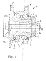
- FIG. 1 shows a wheel bearing assembly 1 with a hub 2, two rows of rolling elements 3 and a vehicle flange 4.
- the hub 2 has a flange 5 for attachment of a vehicle wheel, not shown, and is rotatably supported by the rolling elements 3 about the rotation axis 1a to the vehicle-fixed vehicle flange 4.
- On the hub 2 sits an inner ring 6 on which a number of rolling elements 3 runs.
- the inner ring 6 is held axially on the wheel hub 2 by means of a collar 7.
- the angular contact ball bearing assembly is biased by the collar 7.
- the collar 7 is einmaterialig formed with a hollow portion 8 of the hub 2 and folded from this radially outward.
- a spur gearing 9 is introduced by non-cutting, such as cold extrusion, embossing or rolling.
- the spur toothing is paired with a corresponding counter-toothing 10 on a drive element 11 not shown.
- the teeth 9 and 10 have the same number of teeth 13 to each other, are axially facing each other, play without play into each other and are clamped by means of a bolt 12 axially into each other and against each other.
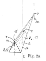
- Embodiments of the teeth 9 and 10 are in FIG. 2 . 2a and 3 shown in simplified form.
- FIG. 2 is the teeth 9, 10 shown in perspective, showing how the individual wedge-shaped tooth 13 head, foot and edge side by radially aligned geometric lines 14, 15, 16 is described, which meet in the intersection P.
- the intersection point P is the common point of intersection for all radially extending geometric lines of the ring gear.
- the tooth angle ⁇ , twice the tooth flank angle ⁇ is constant over the entire radial extent of each individual tooth 13.
- the tooth flank is described by a plane which is inclined by the flank angle ⁇ to the imaginary plane E.
- the plane E extends in the direction of decreasing distance A to two circumferentially adjacent tooth gaps 17. The distance becomes smaller with increasing approach to the axis of rotation.
- the plane E meets in P on the planes Z1, which describe the course of the tooth flanks 18, 19.
- the line 15 drops from the highest tooth height H outside P out. Accordingly, the tooth height H decreases from the outside with decreasing radial distance from the axis of rotation 1a.
- FIG. 3 shows the cross section through teeth 13 of the toothing at the point with the highest tooth height H.
- the tooth gaps 17 of the spur gear teeth 9 are almost completely filled by the teeth of the counter teeth 10 and the gaps of the counter teeth 10 almost completely through the teeth 13 of the spur gear teeth 9.
- the one of the respective teeth 13 common planes Z1 meet the head side in the cutting edge 20 to each other and are each inclined with ⁇ to E.
- the cut edges 20 are arranged with the same pitch T to each other.
- At the foot meet the levels Z1 in the cutting edge 21 to each other.
- the cutting edges 20 or 21 lie in the planes K and F, respectively.
- the theoretical head height H th between the radial head plane K and the radial foot plane F is dependent on ⁇ at a constant circumference U of the toothing 9.
- the vertical distance in the image and at the spur gearing 9 axial distance H is at unchanged height H th of the radii head radius R and root radius r dependent.
- R is greater than r (R> r).
- the backlash-free pairing of the teeth 9 and 10 is so secured, as in the tooth gaps 17 always a distance between the tooth head 22 and center 23 tooth gap 17 remains.
- Torques Md about the axis of rotation 1a cause in the toothing force components FR, FA and FU.
- FA is superimposed by a further Axialkraftkomponente, which are biased by the tension of the teeth of the by means of the bolt 12 against each other.
Landscapes
- Engineering & Computer Science (AREA)
- Mechanical Engineering (AREA)
- General Engineering & Computer Science (AREA)
- Gears, Cams (AREA)
- Rolling Contact Bearings (AREA)
- Mounting Of Bearings Or Others (AREA)
Applications Claiming Priority (2)
| Application Number | Priority Date | Filing Date | Title |
|---|---|---|---|
| DE102005009938A DE102005009938B4 (de) | 2005-03-04 | 2005-03-04 | Stirnverzahnung für eine antreibbare Radnabe |
| EP06706009A EP1853436B1 (de) | 2005-03-04 | 2006-02-24 | Stirnverzahnung für eine antreibbare radnabe |
Related Parent Applications (1)
| Application Number | Title | Priority Date | Filing Date |
|---|---|---|---|
| EP06706009.5 Division | 2006-02-24 |
Publications (2)
| Publication Number | Publication Date |
|---|---|
| EP2363301A1 EP2363301A1 (de) | 2011-09-07 |
| EP2363301B1 true EP2363301B1 (de) | 2013-06-19 |
Family
ID=36405961
Family Applications (2)
| Application Number | Title | Priority Date | Filing Date |
|---|---|---|---|
| EP06706009A Revoked EP1853436B1 (de) | 2005-03-04 | 2006-02-24 | Stirnverzahnung für eine antreibbare radnabe |
| EP11165259.0A Revoked EP2363301B1 (de) | 2005-03-04 | 2006-02-24 | Stirnverzahnung für eine antreibbare Radnabe |
Family Applications Before (1)
| Application Number | Title | Priority Date | Filing Date |
|---|---|---|---|
| EP06706009A Revoked EP1853436B1 (de) | 2005-03-04 | 2006-02-24 | Stirnverzahnung für eine antreibbare radnabe |
Country Status (8)
| Country | Link |
|---|---|
| US (1) | US8444322B2 (pt) |
| EP (2) | EP1853436B1 (pt) |
| JP (1) | JP2008536737A (pt) |
| KR (1) | KR101332449B1 (pt) |
| CN (1) | CN100558567C (pt) |
| BR (1) | BRPI0608094B1 (pt) |
| DE (1) | DE102005009938B4 (pt) |
| WO (1) | WO2006092119A1 (pt) |
Cited By (1)
| Publication number | Priority date | Publication date | Assignee | Title |
|---|---|---|---|---|
| CN112733297A (zh) * | 2021-01-13 | 2021-04-30 | 上海理工大学 | 用于分段式挤出螺杆连接的花键设计方法 |
Families Citing this family (48)
| Publication number | Priority date | Publication date | Assignee | Title |
|---|---|---|---|---|
| DE102005009938B4 (de) | 2005-03-04 | 2012-07-12 | Schaeffler Technologies Gmbh & Co. Kg | Stirnverzahnung für eine antreibbare Radnabe |
| DE102005054285B3 (de) | 2005-11-11 | 2007-05-31 | Gkn Driveline Deutschland Gmbh | Radnaben-Drehgelenk-Anordnung mit Stirnverzahnung und Radlagerung |
| DE102005054283B4 (de) * | 2005-11-11 | 2009-07-02 | Gkn Driveline Deutschland Gmbh | Radnaben-Drehgelenk-Anordnung mit Stirnverzahnung |
| JP5315624B2 (ja) * | 2007-03-29 | 2013-10-16 | 株式会社ジェイテクト | 車輪支持装置 |
| DE102007016427B4 (de) * | 2007-04-05 | 2010-11-25 | Schaeffler Technologies Gmbh & Co. Kg | Lageranordnung einer über ein Drehgelenk antreibbaren Radnabe eines Kraftfahrzeuges |
| EP2441594B1 (en) | 2007-10-03 | 2013-04-24 | JTEKT Corporation | Wheel support apparatus |
| JP5167903B2 (ja) * | 2008-03-28 | 2013-03-21 | 株式会社ジェイテクト | 車輪用軸受装置 |
| DE102007053728B4 (de) * | 2007-11-10 | 2011-12-22 | Schaeffler Technologies Gmbh & Co. Kg | Nabeneinheit zur Übertragung von Drehmomenten sowie eine Antriebseinheit mit der Nabeneinheit |
| JP5098748B2 (ja) * | 2008-03-28 | 2012-12-12 | 株式会社ジェイテクト | 車輪用軸受装置 |
| EP2105321B1 (en) | 2008-03-28 | 2013-03-20 | JTEKT Corporation | Wheel bearing assembly, and manufacturing method thereof |
| JP5261023B2 (ja) * | 2008-05-13 | 2013-08-14 | Ntn株式会社 | 車輪用軸受装置の加工方法 |
| DE102008030496B4 (de) | 2008-06-26 | 2022-12-08 | Schaeffler Technologies AG & Co. KG | Baugruppe mit Stirnverzahnung |
| US20110123264A1 (en) | 2009-11-25 | 2011-05-26 | Gm Global Technology Operations, Inc. | Conical Face Spline for Half-Shafts, Hub Bearings and the Like |
| JP2012045612A (ja) | 2010-08-30 | 2012-03-08 | Jtekt Corp | 車両用ハブユニットの製造方法 |
| JP5556509B2 (ja) | 2010-08-30 | 2014-07-23 | 株式会社ジェイテクト | 車両用ハブユニット |
| DE102010046601A1 (de) | 2010-09-25 | 2011-04-28 | Daimler Ag | Radlageranordnung eines Fahrzeugs |
| DE102011007110A1 (de) * | 2011-04-11 | 2012-10-11 | Bayerische Motoren Werke Aktiengesellschaft | Radlager-Baugruppe eines Fahrzeugs |
| JP5793931B2 (ja) * | 2011-04-21 | 2015-10-14 | 株式会社ジェイテクト | 車両用ハブユニットの加工具及び車両用ハブユニット |
| WO2012159779A1 (de) * | 2011-05-23 | 2012-11-29 | Schaeffler Technologies AG & Co. KG | Wälzlageranordnung mit formschluss unterstützendem verspannungsmittel |
| ITTO20110702A1 (it) * | 2011-07-29 | 2013-01-30 | Skf Ab | Metodo per la formatura di una dentatura frontale su un anello interno di un mozzo ruota |
| JP5870556B2 (ja) | 2011-08-31 | 2016-03-01 | 株式会社ジェイテクト | サイドフェーススプラインの形状測定方法 |
| JP5867121B2 (ja) * | 2012-02-02 | 2016-02-24 | 株式会社ジェイテクト | 車輪支持装置 |
| DE102012208169A1 (de) | 2012-05-16 | 2013-11-21 | Schaeffler Technologies AG & Co. KG | Wälzlagerteil sowie Verfahren zur Wärmebehandlung eines Wälzlagerteils |
| DE102012106440A1 (de) * | 2012-07-17 | 2014-01-23 | Neapco Europe Gmbh | Stirnverzahnung mit versetztem Konstruktionspunkt |
| DE102012214884B3 (de) * | 2012-08-22 | 2014-02-27 | Hirschvogel Umformtechnik Gmbh | Kupplungsanordnung und Kupplungselement |
| JP2014058232A (ja) * | 2012-09-18 | 2014-04-03 | Jtekt Corp | 車両用軸受装置 |
| JP5561338B2 (ja) * | 2012-10-17 | 2014-07-30 | 株式会社ジェイテクト | 車輪用軸受装置 |
| KR20150135236A (ko) * | 2013-01-25 | 2015-12-02 | 주식회사 일진글로벌 | 휠 베어링 및 이를 사용한 휠 베어링 조립체 |
| DE102013205904A1 (de) * | 2013-04-04 | 2014-10-09 | Schaeffler Technologies Gmbh & Co. Kg | Flanschanordnung, Fahrwerksaktuator und Verfahren zur Herstellung der Flanschanordnung |
| DE102013217753B3 (de) * | 2013-09-05 | 2014-12-18 | Hirschvogel Umformtechnik Gmbh | Kupplungselement, Kupplungsanordnung sowie Verfahren zur Herstellung eines Kupplungselements |
| DE102013219958A1 (de) * | 2013-10-01 | 2015-04-02 | Voith Patent Gmbh | Kupplungshälfte zum drehfesten Anschließen einer Welle |
| CN104314989B (zh) * | 2014-10-22 | 2017-07-21 | 德清德曼汽车零部件有限公司 | 轴承外圈半成品 |
| CN104373719A (zh) * | 2014-10-27 | 2015-02-25 | 德清德曼汽车零部件有限公司 | 车用粗车法兰盘 |
| DE102015211455B4 (de) | 2015-06-22 | 2022-11-24 | Ford Global Technologies, Llc | Radmodul für eine angetriebene Achse eines Kraftfahrzeugs |
| DE102015211456A1 (de) | 2015-06-22 | 2016-12-22 | Ford Global Technologies, Llc | Radmodul für eine angetriebene Achse eines Kraftfahrzeugs |
| DE202015103560U1 (de) | 2015-06-22 | 2015-07-23 | Ford Global Technologies, Llc | Radmodul für eine angetriebene Achse eines Kraftfahrzeugs |
| US10247245B2 (en) | 2015-11-10 | 2019-04-02 | Ford Global Technologies, Llc | Bevel facespline with line contact |
| US11009078B2 (en) * | 2018-04-24 | 2021-05-18 | Textron Innovations Inc. | Compressible driveshaft |
| US10830126B2 (en) | 2018-06-29 | 2020-11-10 | Schaeffler Technologies AG & Co. KG | Two-speed accessory drive pulley |
| EP3597948B1 (en) * | 2018-07-20 | 2022-01-26 | Hamilton Sundstrand Corporation | Axial shaft coupling |
| DE102018128745A1 (de) | 2018-11-15 | 2020-05-20 | ILJIN Bearing GmbH | Stirnverzahnung eines Maschinenelementes, Maschinenelement umfassend eine Stirnverzahnung sowie Verfahren zur Herstellung einer Stirnverzahnung einer Welle-Nabe-Verbindung |
| DE202019102438U1 (de) * | 2019-02-21 | 2020-05-25 | Liebherr-Components Biberach Gmbh | Fräsanordnung für eine Schlitzwandfräse |
| CN113059237B (zh) * | 2020-01-02 | 2024-01-19 | 北京智能大艾机器人科技有限公司 | 具有波形端面的花键及其制造方法 |
| DE102020133758A1 (de) | 2020-12-16 | 2022-06-23 | Schaeffler Technologies AG & Co. KG | Stirnverzahnung für Radlageranordnung |
| CN112923890B (zh) * | 2021-02-03 | 2023-06-06 | 浙江万向精工有限公司 | 一种花键齿形误差测量评价方法 |
| DE102021106451A1 (de) | 2021-03-17 | 2022-09-22 | Schaeffler Technologies AG & Co. KG | Stirnverzahnung für Radlageranordnung |
| CN113619330A (zh) * | 2021-09-24 | 2021-11-09 | 上海纳铁福传动系统有限公司 | 一种防启停异响的半轴 |
| CN116292606A (zh) * | 2023-03-23 | 2023-06-23 | 人本股份有限公司 | 具有端面齿的轴承装置 |
Family Cites Families (19)
| Publication number | Priority date | Publication date | Assignee | Title |
|---|---|---|---|---|
| DE440816C (de) | 1924-12-23 | 1927-02-16 | Albert Hirth Dr Ing | Wellenkupplung |
| GB824931A (en) | 1955-01-06 | 1959-12-09 | Zd Y V I | A permanent coupling between two rotatable members |
| NL176011C (nl) * | 1974-09-30 | 1985-02-01 | Skf Ind Trading & Dev | Lagereenheid. |
| FR2455209B2 (fr) | 1979-04-24 | 1986-07-25 | Glaenzer Spicer Sa | Roulement a deux rangees d'elements de roulement et dispositif de montage de roue de vehicule |
| EP0048101B1 (en) * | 1980-09-13 | 1985-02-20 | GKN Transmissions Limited | Bearing and universal joint assembly |
| DE3116720C1 (de) * | 1981-04-28 | 1982-10-28 | Loehr & Bromkamp Gmbh | Lagerungsanordnung einer ueber ein Gleichlaufdrehgelenk antreibbaren Radnabe |
| DE3219747A1 (de) * | 1982-05-26 | 1983-12-01 | Skf Kugellagerfabriken Gmbh, 8720 Schweinfurt | Formschluessige verbindung zwischen einer antriebswelle und einer waelzlagereinheit |
| NL8503359A (nl) * | 1985-12-05 | 1987-07-01 | Kuiken Nv | Kroonwieloverbrenging. |
| DE3636243A1 (de) * | 1986-10-24 | 1988-05-11 | Loehr & Bromkamp Gmbh | Radlager-(ny)leichlaufgelenk-einheit |
| NL9401735A (nl) * | 1994-10-19 | 1996-06-03 | Crown Gear Bv | Tandwieloverbrenging van een cilindrisch rondsel met een kroonwiel, het kroonwiel dat toegepast wordt in deze tandwieloverbrenging, een werkwijze volgens welke het kroonwiel gemaakt kan worden alsmede een gereedschap waarmee het kroonwiel gemaakt kan worden. |
| FR2738775B1 (fr) * | 1995-09-18 | 1997-12-05 | Guimbretiere Pierre | Moyeu de roue motrice pour vehicule automobile |
| DE19547096A1 (de) * | 1995-12-16 | 1997-06-19 | Audi Ag | Radlagerung |
| DE29616818U1 (de) | 1996-09-26 | 1998-01-29 | Weiss Wolfgang | Spielfreie Radbefestigung |
| DE19639729A1 (de) * | 1996-09-26 | 1998-04-16 | Weiss Wolfgang | Spielfreie Radbefestigung |
| DE19751855C1 (de) * | 1997-11-22 | 1999-04-29 | Gkn Automotive Ag | Verbindungsanordnung an einer Gelenkwelle |
| US6146022A (en) * | 1997-12-25 | 2000-11-14 | Ntn Corporation | Hub unit bearing for wheel |
| DE20020455U1 (de) | 2000-12-02 | 2001-02-15 | Hafner Walter | Kupplung für die Verbindung zweier koaxialer Wellen |
| DE102005009938B4 (de) | 2005-03-04 | 2012-07-12 | Schaeffler Technologies Gmbh & Co. Kg | Stirnverzahnung für eine antreibbare Radnabe |
| DE102005018126A1 (de) * | 2005-04-20 | 2006-10-26 | Schaeffler Kg | Radlagergelenkeinheit |
-
2005
- 2005-03-04 DE DE102005009938A patent/DE102005009938B4/de active Active
-
2006
- 2006-02-24 EP EP06706009A patent/EP1853436B1/de not_active Revoked
- 2006-02-24 WO PCT/DE2006/000340 patent/WO2006092119A1/de active Application Filing
- 2006-02-24 US US11/817,590 patent/US8444322B2/en active Active
- 2006-02-24 EP EP11165259.0A patent/EP2363301B1/de not_active Revoked
- 2006-02-24 CN CNB2006800071496A patent/CN100558567C/zh active Active
- 2006-02-24 BR BRPI0608094-4A patent/BRPI0608094B1/pt active IP Right Grant
- 2006-02-24 JP JP2008502234A patent/JP2008536737A/ja not_active Withdrawn
- 2006-02-24 KR KR1020077022497A patent/KR101332449B1/ko active IP Right Grant
Cited By (2)
| Publication number | Priority date | Publication date | Assignee | Title |
|---|---|---|---|---|
| CN112733297A (zh) * | 2021-01-13 | 2021-04-30 | 上海理工大学 | 用于分段式挤出螺杆连接的花键设计方法 |
| CN112733297B (zh) * | 2021-01-13 | 2022-07-19 | 上海理工大学 | 用于分段式挤出螺杆连接的花键设计方法 |
Also Published As
| Publication number | Publication date |
|---|---|
| EP2363301A1 (de) | 2011-09-07 |
| CN100558567C (zh) | 2009-11-11 |
| BRPI0608094B1 (pt) | 2020-03-31 |
| BRPI0608094A8 (pt) | 2016-08-16 |
| EP1853436A1 (de) | 2007-11-14 |
| WO2006092119A1 (de) | 2006-09-08 |
| BRPI0608094A2 (pt) | 2009-11-10 |
| CN101132934A (zh) | 2008-02-27 |
| KR20070114799A (ko) | 2007-12-04 |
| US8444322B2 (en) | 2013-05-21 |
| US20080175526A1 (en) | 2008-07-24 |
| EP1853436B1 (de) | 2011-09-14 |
| DE102005009938B4 (de) | 2012-07-12 |
| DE102005009938A1 (de) | 2006-09-07 |
| KR101332449B1 (ko) | 2013-11-25 |
| JP2008536737A (ja) | 2008-09-11 |
Similar Documents
| Publication | Publication Date | Title |
|---|---|---|
| EP2363301B1 (de) | Stirnverzahnung für eine antreibbare Radnabe | |
| EP1853437B1 (de) | Radlageranordnung mit stirnverzahnung | |
| EP1866553B1 (de) | Bund mit stirnseitigen zähnen für eine antreibbare radnabe | |
| EP1910100B1 (de) | Radlageranordnung mit stirnverzahnung | |
| WO2008122277A2 (de) | Radlageranordnung | |
| EP1945437A1 (de) | Mehrwellenextruder | |
| DD252862A5 (de) | Elastische wellenkupplung | |
| EP3385558B1 (de) | Lamellenkupplung | |
| EP1298353A2 (de) | Zahnradpaarung und deren Verwendung | |
| DE2755131A1 (de) | Kupplung zum starren verbinden zweier gleichachsiger und zum uebertragen von drehmoment geeigneter maschinenteile | |
| EP2646712B1 (de) | Zahnradgetriebe mit schrägverzahnung | |
| EP1178232B1 (de) | Flanschmitnehmer für ein Kardangelenk und Gelenkwelle | |
| EP3143294B1 (de) | Vorrichtung zum sichern eines spannelements gegen ungewolltes lösen | |
| EP0025901A2 (de) | Elastische Kupplung | |
| DE202005021961U1 (de) | Stirnverzahnung für eine antreibbare Radnabe | |
| DE102007040590A1 (de) | Kraftübertragungssystem | |
| DE102019130321B4 (de) | Radlagereinheit für ein Kraftfahrzeug sowie Verfahren zum Herstellen einer Radlagereinheit | |
| EP1188945B1 (de) | Steckbare, drehelastische Wellenkupplung | |
| EP3293407B1 (de) | Welle-nabe-verbindung | |
| DE102020124855A1 (de) | Welle mit richtungsabhängiger Belastbarkeit und Kraftfahrzeug | |
| EP1234990B1 (de) | Schalenkupplung zur drehfesten Verbindung von Wellen | |
| EP1683980B1 (de) | Flanschmitnehmer für ein Kardangelenk und Gelenkwelle | |
| WO2024110136A1 (de) | Planetengetriebe mit planetenträger und hohlrad | |
| EP2019222B1 (de) | Flexible Wellenkupplung mit Lamellenpaket und Formschlusselementen | |
| DE102023004266A1 (de) | Planetengetriebe mit Planetenträger und Hohlrad |
Legal Events
| Date | Code | Title | Description |
|---|---|---|---|
| PUAI | Public reference made under article 153(3) epc to a published international application that has entered the european phase |
Free format text: ORIGINAL CODE: 0009012 |
|
| 17P | Request for examination filed |
Effective date: 20110509 |
|
| AC | Divisional application: reference to earlier application |
Ref document number: 1853436 Country of ref document: EP Kind code of ref document: P |
|
| AK | Designated contracting states |
Kind code of ref document: A1 Designated state(s): FR GB IT |
|
| 17Q | First examination report despatched |
Effective date: 20110822 |
|
| RAP1 | Party data changed (applicant data changed or rights of an application transferred) |
Owner name: SCHAEFFLER TECHNOLOGIES AG & CO. KG |
|
| RIC1 | Information provided on ipc code assigned before grant |
Ipc: B60B 27/00 20060101AFI20120904BHEP Ipc: F16C 43/04 20060101ALI20120904BHEP Ipc: F16D 1/076 20060101ALI20120904BHEP |
|
| GRAP | Despatch of communication of intention to grant a patent |
Free format text: ORIGINAL CODE: EPIDOSNIGR1 |
|
| GRAS | Grant fee paid |
Free format text: ORIGINAL CODE: EPIDOSNIGR3 |
|
| GRAA | (expected) grant |
Free format text: ORIGINAL CODE: 0009210 |
|
| AC | Divisional application: reference to earlier application |
Ref document number: 1853436 Country of ref document: EP Kind code of ref document: P |
|
| AK | Designated contracting states |
Kind code of ref document: B1 Designated state(s): FR GB IT |
|
| REG | Reference to a national code |
Ref country code: GB Ref legal event code: FG4D Free format text: NOT ENGLISH |
|
| RAP2 | Party data changed (patent owner data changed or rights of a patent transferred) |
Owner name: SCHAEFFLER TECHNOLOGIES GMBH & CO. KG |
|
| PLBI | Opposition filed |
Free format text: ORIGINAL CODE: 0009260 |
|
| PLBI | Opposition filed |
Free format text: ORIGINAL CODE: 0009260 |
|
| 26 | Opposition filed |
Opponent name: SKF GMBH Effective date: 20140313 |
|
| 26 | Opposition filed |
Opponent name: UDO PREUSS Effective date: 20140318 |
|
| PLAX | Notice of opposition and request to file observation + time limit sent |
Free format text: ORIGINAL CODE: EPIDOSNOBS2 |
|
| PLBB | Reply of patent proprietor to notice(s) of opposition received |
Free format text: ORIGINAL CODE: EPIDOSNOBS3 |
|
| PLAF | Information modified related to communication of a notice of opposition and request to file observations + time limit |
Free format text: ORIGINAL CODE: EPIDOSCOBS2 |
|
| RAP2 | Party data changed (patent owner data changed or rights of a patent transferred) |
Owner name: SCHAEFFLER TECHNOLOGIES AG & CO. KG |
|
| RDAF | Communication despatched that patent is revoked |
Free format text: ORIGINAL CODE: EPIDOSNREV1 |
|
| REG | Reference to a national code |
Ref country code: FR Ref legal event code: PLFP Year of fee payment: 11 |
|
| PGFP | Annual fee paid to national office [announced via postgrant information from national office to epo] |
Ref country code: IT Payment date: 20160224 Year of fee payment: 11 |
|
| RDAG | Patent revoked |
Free format text: ORIGINAL CODE: 0009271 |
|
| STAA | Information on the status of an ep patent application or granted ep patent |
Free format text: STATUS: PATENT REVOKED |
|
| PGFP | Annual fee paid to national office [announced via postgrant information from national office to epo] |
Ref country code: FR Payment date: 20160229 Year of fee payment: 11 Ref country code: GB Payment date: 20160226 Year of fee payment: 11 |
|
| 27W | Patent revoked |
Effective date: 20151225 |
|
| GBPR | Gb: patent revoked under art. 102 of the ep convention designating the uk as contracting state |
Effective date: 20151225 |
|
| P01 | Opt-out of the competence of the unified patent court (upc) registered |
Effective date: 20230523 |