EP2363301B1 - Front cogging for a driven hub - Google Patents
Front cogging for a driven hub Download PDFInfo
- Publication number
- EP2363301B1 EP2363301B1 EP11165259.0A EP11165259A EP2363301B1 EP 2363301 B1 EP2363301 B1 EP 2363301B1 EP 11165259 A EP11165259 A EP 11165259A EP 2363301 B1 EP2363301 B1 EP 2363301B1
- Authority
- EP
- European Patent Office
- Prior art keywords
- tooth
- toothing system
- spur toothing
- wheel hub
- teeth
- Prior art date
- Legal status (The legal status is an assumption and is not a legal conclusion. Google has not performed a legal analysis and makes no representation as to the accuracy of the status listed.)
- Revoked
Links
Images


Classifications
-
- B—PERFORMING OPERATIONS; TRANSPORTING
- B60—VEHICLES IN GENERAL
- B60B—VEHICLE WHEELS; CASTORS; AXLES FOR WHEELS OR CASTORS; INCREASING WHEEL ADHESION
- B60B27/00—Hubs
- B60B27/06—Hubs adapted to be fixed on axle
-
- F—MECHANICAL ENGINEERING; LIGHTING; HEATING; WEAPONS; BLASTING
- F16—ENGINEERING ELEMENTS AND UNITS; GENERAL MEASURES FOR PRODUCING AND MAINTAINING EFFECTIVE FUNCTIONING OF MACHINES OR INSTALLATIONS; THERMAL INSULATION IN GENERAL
- F16D—COUPLINGS FOR TRANSMITTING ROTATION; CLUTCHES; BRAKES
- F16D1/00—Couplings for rigidly connecting two coaxial shafts or other movable machine elements
- F16D1/06—Couplings for rigidly connecting two coaxial shafts or other movable machine elements for attachment of a member on a shaft or on a shaft-end
- F16D1/076—Couplings for rigidly connecting two coaxial shafts or other movable machine elements for attachment of a member on a shaft or on a shaft-end by clamping together two faces perpendicular to the axis of rotation, e.g. with bolted flanges
-
- B—PERFORMING OPERATIONS; TRANSPORTING
- B60—VEHICLES IN GENERAL
- B60B—VEHICLE WHEELS; CASTORS; AXLES FOR WHEELS OR CASTORS; INCREASING WHEEL ADHESION
- B60B27/00—Hubs
-
- B—PERFORMING OPERATIONS; TRANSPORTING
- B60—VEHICLES IN GENERAL
- B60B—VEHICLE WHEELS; CASTORS; AXLES FOR WHEELS OR CASTORS; INCREASING WHEEL ADHESION
- B60B27/00—Hubs
- B60B27/0005—Hubs with ball bearings
-
- B—PERFORMING OPERATIONS; TRANSPORTING
- B60—VEHICLES IN GENERAL
- B60B—VEHICLE WHEELS; CASTORS; AXLES FOR WHEELS OR CASTORS; INCREASING WHEEL ADHESION
- B60B27/00—Hubs
- B60B27/0015—Hubs for driven wheels
- B60B27/0021—Hubs for driven wheels characterised by torque transmission means from drive axle
- B60B27/0031—Hubs for driven wheels characterised by torque transmission means from drive axle of the axial type, e.g. front teeth
-
- B—PERFORMING OPERATIONS; TRANSPORTING
- B60—VEHICLES IN GENERAL
- B60B—VEHICLE WHEELS; CASTORS; AXLES FOR WHEELS OR CASTORS; INCREASING WHEEL ADHESION
- B60B27/00—Hubs
- B60B27/0078—Hubs characterised by the fixation of bearings
- B60B27/0084—Hubs characterised by the fixation of bearings caulking to fix inner race
-
- B—PERFORMING OPERATIONS; TRANSPORTING
- B60—VEHICLES IN GENERAL
- B60B—VEHICLE WHEELS; CASTORS; AXLES FOR WHEELS OR CASTORS; INCREASING WHEEL ADHESION
- B60B27/00—Hubs
- B60B27/0094—Hubs one or more of the bearing races are formed by the hub
-
- F—MECHANICAL ENGINEERING; LIGHTING; HEATING; WEAPONS; BLASTING
- F16—ENGINEERING ELEMENTS AND UNITS; GENERAL MEASURES FOR PRODUCING AND MAINTAINING EFFECTIVE FUNCTIONING OF MACHINES OR INSTALLATIONS; THERMAL INSULATION IN GENERAL
- F16C—SHAFTS; FLEXIBLE SHAFTS; ELEMENTS OR CRANKSHAFT MECHANISMS; ROTARY BODIES OTHER THAN GEARING ELEMENTS; BEARINGS
- F16C19/00—Bearings with rolling contact, for exclusively rotary movement
- F16C19/02—Bearings with rolling contact, for exclusively rotary movement with bearing balls essentially of the same size in one or more circular rows
- F16C19/14—Bearings with rolling contact, for exclusively rotary movement with bearing balls essentially of the same size in one or more circular rows for both radial and axial load
- F16C19/18—Bearings with rolling contact, for exclusively rotary movement with bearing balls essentially of the same size in one or more circular rows for both radial and axial load with two or more rows of balls
- F16C19/181—Bearings with rolling contact, for exclusively rotary movement with bearing balls essentially of the same size in one or more circular rows for both radial and axial load with two or more rows of balls with angular contact
- F16C19/183—Bearings with rolling contact, for exclusively rotary movement with bearing balls essentially of the same size in one or more circular rows for both radial and axial load with two or more rows of balls with angular contact with two rows at opposite angles
- F16C19/184—Bearings with rolling contact, for exclusively rotary movement with bearing balls essentially of the same size in one or more circular rows for both radial and axial load with two or more rows of balls with angular contact with two rows at opposite angles in O-arrangement
- F16C19/186—Bearings with rolling contact, for exclusively rotary movement with bearing balls essentially of the same size in one or more circular rows for both radial and axial load with two or more rows of balls with angular contact with two rows at opposite angles in O-arrangement with three raceways provided integrally on parts other than race rings, e.g. third generation hubs
-
- F—MECHANICAL ENGINEERING; LIGHTING; HEATING; WEAPONS; BLASTING
- F16—ENGINEERING ELEMENTS AND UNITS; GENERAL MEASURES FOR PRODUCING AND MAINTAINING EFFECTIVE FUNCTIONING OF MACHINES OR INSTALLATIONS; THERMAL INSULATION IN GENERAL
- F16C—SHAFTS; FLEXIBLE SHAFTS; ELEMENTS OR CRANKSHAFT MECHANISMS; ROTARY BODIES OTHER THAN GEARING ELEMENTS; BEARINGS
- F16C43/00—Assembling bearings
- F16C43/04—Assembling rolling-contact bearings
-
- F—MECHANICAL ENGINEERING; LIGHTING; HEATING; WEAPONS; BLASTING
- F16—ENGINEERING ELEMENTS AND UNITS; GENERAL MEASURES FOR PRODUCING AND MAINTAINING EFFECTIVE FUNCTIONING OF MACHINES OR INSTALLATIONS; THERMAL INSULATION IN GENERAL
- F16C—SHAFTS; FLEXIBLE SHAFTS; ELEMENTS OR CRANKSHAFT MECHANISMS; ROTARY BODIES OTHER THAN GEARING ELEMENTS; BEARINGS
- F16C2326/00—Articles relating to transporting
- F16C2326/01—Parts of vehicles in general
- F16C2326/02—Wheel hubs or castors
Definitions
- the invention relates to an end toothing of a ring gear extending in the circumferential direction about a rotation axis on a wheel bearing arrangement for a drivable hub, wherein the spur gear is provided for a backlash-free engagement in a counter toothing facing the spur gear teeth and the teeth of the spur gear teeth are wedge-shaped such that the geometric Lines of the spur toothing coincide centrally in a common point on the axis of rotation and thus extend the teeth in the radial direction on the axis of rotation.
- Such a spur gear is in DE 31 16 720 C1 described in more detail.
- the counter-toothing is usually formed on a bell or on a stump of the bell of a constant velocity joint.
- the assembly of the joint part to the hub is on the one hand due to the self-centering simple, on the other hand, however, requires a very high axial biasing force.
- the flanks of all teeth of the spur gear teeth are engaged with both flanks of all teeth of the counter teeth.
- the teeth are axially braced by means of one or more screw elements. Torques are transmitted to the wheel hub by the force - fit generated from surface pressure.
- connection of the joint part with a wheel hub is particularly advantageous when high torque from the drive to the wheel or u.U. should also be transmitted in the reverse moment flow.
- the commonly used pairings of internal and external gears are space-technically and thus exhausted in terms of strength, so that the spur gear is a safe and space-saving alternative to these.
- the rigid design for transmitting high torque to the wheel can then be detrimental if, in the event of overload, a breakage of the wheel hub in the worst case leads to the loss of the vehicle wheel.
- spur toothing is the DE 31 16 720 C1 view, which forms a sprocket with wedge-shaped teeth and play with a counter teeth engaged.
- wheel bearing units are known from the prior art, which has a front-toothed wheel hub ( US 4,047,770 ; US 6,146,022 ) or even an end-toothed Wälznietbund ( DE 36 36 243 A1 ) exhibit.
- the object of the invention is therefore to provide a spur toothing with the design of the aforementioned disadvantages are avoided.
- the invention is based on the finding that the size of the radii influences the height of the teeth of the spur toothing and thus the resistance of the toothing to stresses. Embodiments of the invention therefore provide that a quotient of the largest theoretical tooth height of the respective tooth and the head radius is at least the number five and at most the number nine: 5 ⁇ H th / R ⁇ 9 .
- the theoretical tooth height in the symmetry or division plane is the largest axial distance between a first cutting edge in the head plane and a second cutting edge in the foot plane of the tooth.
- two mutually facing geometric planes meet, through which at least the part of the flanks is described, which is in engagement with the counter-toothing. Accordingly, meet in the first cutting edge, the geometric planes of the flanks of a tooth, which include the double flank angle between the tooth head side.
- the geometric planes of two teeth which are opposite to each other on one tooth gap, meet adjacent teeth on the tooth base side.
- a quotient of the largest theoretical tooth height of the respective tooth and the root radius is at least the number seven and at most the number eleven: 7 ⁇ H th / r ⁇ 11th
- a quotient of the largest theoretical tooth height of the respective tooth and the theoretical tooth root width at least 0.9 and at most 1.3 0 . 9 ⁇ H th / B th ⁇ 1 . 3 .
- flanks provided for the engagement of the teeth of the spur toothing are each inclined with a flank angle greater than 20 ° and less than 30 °.
- the flank angle is in the case of a symmetrical toothing half of the tooth angle.
- the flanks are inclined with the flank angle to an imaginary and departing from the axis of rotation graduation plane.
- the dimensions and changes in the dimensions of serrations are limited to wheel bearings for reasons of space limitations.
- the pitch circle diameter (average circumference of the spur toothing about the axis of rotation) of the gearing is therefore generally enshrined within very narrow limits. Accordingly, the behavior of the teeth, for example, against loads from the drive torques are hardly or not influenced by changes in the pitch circle of the teeth.
- the geometry of the individual teeth of the toothing on the flank angle is influenced so that an optimum number of teeth can be set to a predetermined extent in terms of assembly and with respect to the loads of torques.
- the flank angle of the effective flanks without clearance in engagement with the counter-toothing is preferably 22.5 °.
- each tooth in the tooth root is designed so that the spur toothing transmits high torques in nominal operation, but yields at a pre- prescribed breaking moment.
- tooth spaces of the spur toothing are concave rounded at least between two each of the tooth gap opposite flanks (edge to edge) with at least one Sriradius - and that the tooth tip of the respective teeth of at least one flank other flank of a respective one of the teeth is rounded with at least one convex head radius. It is also envisaged that the head radius is always greater than the foot radius. Due to this, the tooth tip of the counter teeth does not contact the tooth gap of the spur gear teeth in the ground and the tooth tip of the spur gear teeth does not contact the tooth gap of the counter teeth in the ground. The play-free concern of the effective flanks is secured.
- the spur toothing and the counter toothing according to the invention can be identical. If the toothing is preferably introduced without cutting by forming with so-called topper tools, the same tool can be used for both toothings.
- a predetermined breaking point in the spur toothing is provided on the wheel hub bearing in the torque connection between the drive shaft and the wheel, which is arranged away from safety-relevant parts, for example, from the wheel bearing.
- the loaded by torques about the axis of rotation total cross-section of the material of the spur gear thus has a lower resistance to deformation, which leads to torque from overloading specifically for yielding deformation of the teeth.
- Each further loaded by the same torque and remote from the spur toothing cross-section of the material of the wheel hub has higher resistance moments.
- the total cross section is the sum of all simultaneously with the action of the respective total torque proportionately loaded by torques individual cross sections of the teeth, tooth roots and / or cross sections in the material of the hub at the transitions to the teeth. In case of overload is thus by destroying the meshing worst if the drive to the hub interrupted, but the wheel bearing remains intact.
- the pairing of the serrations is designed as a safety ratchet coupling.
- the wheel hub and the drive element are clamped by means of at least one bolt axially against bias against each other.
- the bolt has a total, or at any portion / cross section of its material, but in any case at a weakest point - at least of any cross-section - a lower resistance to deformation by loads from torques on, as any portion of the wheel bearing unit, which is loaded by the torques or by resulting from the torque forces.
- This measure is effective in particular in the cases in which the spur toothing or the mating due to the large Operanikmessers is designed so rigid that it is not suitable as a predetermined breaking point.
- a central bolt or a plurality of bolts arranged around the axis of rotation have an overall cross-section which is designed according to the size of the required breaking torque.
- On the teeth acting torques at overloads are implemented in the teeth due to the flank geometry according to the invention in axial forces that stretch the bolt axially far enough that the tooth flanks ascend each other and eventually separate from each other, so that the rotationally fixed connection is repealed.
- the bolt is axially at least elastically but also plastically yielding deformable so that this lower resistance to plastic and elastic deformation at least in the axial direction than a loaded simultaneously by the axial preload and the torques total cross-section of the teeth.
- the resistance is an axial force on the screw less than or equal to an axial release force at which the intermeshing teeth begin to disengage from each other against the biasing force.
- Resistance in this invention means the ability of a surface portion of the material to withstand bending (resistive, torsional, tensile, and compressive) loads.
- the loads are first introduced as a moment about the axis of rotation and then implemented on the teeth in axial and tangential force components.
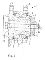
- FIG. 1 shows a wheel bearing assembly 1 with a hub 2, two rows of rolling elements 3 and a vehicle flange 4.
- the hub 2 has a flange 5 for attachment of a vehicle wheel, not shown, and is rotatably supported by the rolling elements 3 about the rotation axis 1a to the vehicle-fixed vehicle flange 4.
- On the hub 2 sits an inner ring 6 on which a number of rolling elements 3 runs.
- the inner ring 6 is held axially on the wheel hub 2 by means of a collar 7.
- the angular contact ball bearing assembly is biased by the collar 7.
- the collar 7 is einmaterialig formed with a hollow portion 8 of the hub 2 and folded from this radially outward.
- a spur gearing 9 is introduced by non-cutting, such as cold extrusion, embossing or rolling.
- the spur toothing is paired with a corresponding counter-toothing 10 on a drive element 11 not shown.
- the teeth 9 and 10 have the same number of teeth 13 to each other, are axially facing each other, play without play into each other and are clamped by means of a bolt 12 axially into each other and against each other.
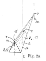
- Embodiments of the teeth 9 and 10 are in FIG. 2 . 2a and 3 shown in simplified form.
- FIG. 2 is the teeth 9, 10 shown in perspective, showing how the individual wedge-shaped tooth 13 head, foot and edge side by radially aligned geometric lines 14, 15, 16 is described, which meet in the intersection P.
- the intersection point P is the common point of intersection for all radially extending geometric lines of the ring gear.
- the tooth angle ⁇ , twice the tooth flank angle ⁇ is constant over the entire radial extent of each individual tooth 13.
- the tooth flank is described by a plane which is inclined by the flank angle ⁇ to the imaginary plane E.
- the plane E extends in the direction of decreasing distance A to two circumferentially adjacent tooth gaps 17. The distance becomes smaller with increasing approach to the axis of rotation.
- the plane E meets in P on the planes Z1, which describe the course of the tooth flanks 18, 19.
- the line 15 drops from the highest tooth height H outside P out. Accordingly, the tooth height H decreases from the outside with decreasing radial distance from the axis of rotation 1a.
- FIG. 3 shows the cross section through teeth 13 of the toothing at the point with the highest tooth height H.
- the tooth gaps 17 of the spur gear teeth 9 are almost completely filled by the teeth of the counter teeth 10 and the gaps of the counter teeth 10 almost completely through the teeth 13 of the spur gear teeth 9.
- the one of the respective teeth 13 common planes Z1 meet the head side in the cutting edge 20 to each other and are each inclined with ⁇ to E.
- the cut edges 20 are arranged with the same pitch T to each other.
- At the foot meet the levels Z1 in the cutting edge 21 to each other.
- the cutting edges 20 or 21 lie in the planes K and F, respectively.
- the theoretical head height H th between the radial head plane K and the radial foot plane F is dependent on ⁇ at a constant circumference U of the toothing 9.
- the vertical distance in the image and at the spur gearing 9 axial distance H is at unchanged height H th of the radii head radius R and root radius r dependent.
- R is greater than r (R> r).
- the backlash-free pairing of the teeth 9 and 10 is so secured, as in the tooth gaps 17 always a distance between the tooth head 22 and center 23 tooth gap 17 remains.
- Torques Md about the axis of rotation 1a cause in the toothing force components FR, FA and FU.
- FA is superimposed by a further Axialkraftkomponente, which are biased by the tension of the teeth of the by means of the bolt 12 against each other.
Landscapes
- Engineering & Computer Science (AREA)
- Mechanical Engineering (AREA)
- General Engineering & Computer Science (AREA)
- Gears, Cams (AREA)
- Rolling Contact Bearings (AREA)
- Mounting Of Bearings Or Others (AREA)
Description
Die Erfindung betrifft eine Stirnverzahnung eines in Umfangsrichtung um eine Rotationsachse verlaufenden Zahnkranzes an einer Radlageranordnung für eine antreibbare Radnabe, wobei die Stirnverzahnung für einen spielfreien Eingriff in eine der Stirnverzahnung zugewandte Gegenverzahnung vorgesehen ist und dabei die Zähne der Stirnverzahnung so keilförmig ausgebildet sind, dass die geometrischen Linien der Stirnverzahnung zentral in einem gemeinsamen Punkt auf der Rotationsachse zusammentreffen und sich die Zähne somit in radiale Richtung auf die Rotationsachse erstrecken.The invention relates to an end toothing of a ring gear extending in the circumferential direction about a rotation axis on a wheel bearing arrangement for a drivable hub, wherein the spur gear is provided for a backlash-free engagement in a counter toothing facing the spur gear teeth and the teeth of the spur gear teeth are wedge-shaped such that the geometric Lines of the spur toothing coincide centrally in a common point on the axis of rotation and thus extend the teeth in the radial direction on the axis of rotation.
Eine derartige Stirnverzahnung ist in
Bei der Montage des Antriebselementes in die Radnabenanordnung zentrieren sich das Antriebselement und die Radnabe bezüglich der Rotationsachse aufgrund der Geometrie der Hirth-Verzahnung zueinander. Eine hohe Rundlaufgenauigkeit an der Verbindung im Fahrbetrieb ist somit abgesichert.When mounting the drive element in the hub assembly, the drive element and the hub center with respect to the axis of rotation due to the geometry of the Hirth toothing to each other. A high concentricity at the connection while driving is thus ensured.
Die Montage des Gelenkteils zur Nabe gestaltet sich einerseits aufgrund der Selbstzentrierung einfach, bedarf andererseits jedoch einer sehr hohen axialen Vorspannkraft.The assembly of the joint part to the hub is on the one hand due to the self-centering simple, on the other hand, however, requires a very high axial biasing force.
Die Flanken aller Zähne der Stirnverzahnung stehen mit beiden Flanken aller Zähne der Gegenverzahnung im Eingriff. Die Verzahnungen sind mittels eines oder mehrerer Schraubelemente axial verspannt. Drehmomente werden durch den aus Flächenpressung erzeugten Kraft - Formschluss auf die Radnabe übertragen.The flanks of all teeth of the spur gear teeth are engaged with both flanks of all teeth of the counter teeth. The teeth are axially braced by means of one or more screw elements. Torques are transmitted to the wheel hub by the force - fit generated from surface pressure.
Die Verbindung des Gelenkteils mit einer Radnabe ist insbesondere dann von Vorteil, wenn hohe Momente vom Antrieb zum Rad oder u.U. auch im umgekehrten Momentenfluss übertragen werden sollen. Oft sind die üblicherweise eingesetzten Paarungen aus Innen- und Außenverzahnungen bauraumtechnisch und somit hinsichtlich der Festigkeit ausgereizt, so dass die Stirnverzahnung eine sichere und Bauraum sparende Alternative zu diesen ist. Die starre Auslegung zur Übertragung von hohen Drehmomenten zum Rad kann sich dann nachteilig auswirken, wenn im Falle von Überlast ein Bruch der Radnabe im ungünstigsten Fall zum Verlust des Fahrzeugrades führt.The connection of the joint part with a wheel hub is particularly advantageous when high torque from the drive to the wheel or u.U. should also be transmitted in the reverse moment flow. Often the commonly used pairings of internal and external gears are space-technically and thus exhausted in terms of strength, so that the spur gear is a safe and space-saving alternative to these. The rigid design for transmitting high torque to the wheel can then be detrimental if, in the event of overload, a breakage of the wheel hub in the worst case leads to the loss of the vehicle wheel.
Als gattungsbildend ist die Stirnverzahnung der
Ferner sind Radlagereinheiten aus dem Stand der Technik bekannt, die eine stirnverzahnte Radnabe (
Die Aufgabe der Erfindung ist es daher, eine Stirnverzahnung zu schaffen mit deren Gestaltung die zuvor genannten Nachteile vermieden werden.The object of the invention is therefore to provide a spur toothing with the design of the aforementioned disadvantages are avoided.
Erfindungsgemäß wird diese Aufgabe von einer Stirnverzahnung gemäß dem unabhängigen Anspruch 1 gelöst.According to the invention this object is achieved by a face gear according to the independent claim 1.
Der Erfindung liegt die Erkenntnis zugrunde, dass die Größe der Radien die Höhe der Zähne der Stirnverzahnung und damit den Widerstand der Verzahnung gegen Belastungen beeinflusst. Ausgestaltungen der Erfindung sehen deshalb vor, dass ein Quotient aus größter theoretischer Zahnhöhe des jeweiligen Zahnes und dem Kopfradius mindestens der Zahl Fünf und maximal der Zahl Neun ist: ![]()
![]()
Die theoretische Zahnhöhe ist in der Symmetrie oder Teilungsebene der größte axiale Abstand zwischen einer ersten Schnittkante in der Kopfebene und einer zweiten Schnittkante in der Fußebene des Zahnes. In den Schnittkanten treffen jeweils zwei einander zugewandte geometrische Ebenen aufeinander, durch die zumindest der Teil der Flanken beschrieben ist, der mit der Gegenverzahnung im Eingriff steht. Demnach treffen sich in der ersten Schnittkante die geometrischen Ebenen der Flanken eines Zahnes, die den doppelten Flankenwinkel zwischen sich einschließen zahnkopfseitig. In der zweiten Schnittkante treffen sich die geometrischen Ebenen von jeweils zwei an jeweils einer Zahnlücke gegenüberliegenden Flanken zueinander benachbarter Zähne zahnfußseitig.The theoretical tooth height in the symmetry or division plane is the largest axial distance between a first cutting edge in the head plane and a second cutting edge in the foot plane of the tooth. In the cutting edges in each case two mutually facing geometric planes meet, through which at least the part of the flanks is described, which is in engagement with the counter-toothing. Accordingly, meet in the first cutting edge, the geometric planes of the flanks of a tooth, which include the double flank angle between the tooth head side. In the second cutting edge, the geometric planes of two teeth, which are opposite to each other on one tooth gap, meet adjacent teeth on the tooth base side.
Gleichzeitig oder alternativ ist ein Quotient aus größter theoretischer Zahnhöhe des jeweiligen Zahnes und dem Fußradius mindestens der Zahl Sieben und maximal der Zahl Elf: ![]()
![]()
Gleichzeitig oder alternativ ist ein Quotient aus größter theoretischer Zahnhöhe des jeweiligen Zahnes und der theoretischen Zahnfußbreite mindestens dem Wert 0,9 und maximal dem Wert 1,3: ![]()
![]()
Die theoretische Zahnfußbreite ist jeweils der Abstand zwischen zwei zueinander benachbarten der zahnfußseitigen Schnittkanten.The theoretical Zahnfußbreite is in each case the distance between two mutually adjacent the zahnfußseitigen cut edges.
Vorteilhafterweise sind die für den Eingriff vorgesehenen Flanken der Zähne der Stirnverzahnung jeweils mit einem Flankenwinkel größer als 20° und kleiner als 30° geneigt. Der Flankenwinkel ist im Falle einer symmetrisch ausgebildeten Verzahnung die Hälfte des Zahnwinkels. Die Flanken sind mit dem Flankenwinkel zu einer gedachten und von der Rotationsachse abgehenden Teilungsebene geneigt.Advantageously, the flanks provided for the engagement of the teeth of the spur toothing are each inclined with a flank angle greater than 20 ° and less than 30 °. The flank angle is in the case of a symmetrical toothing half of the tooth angle. The flanks are inclined with the flank angle to an imaginary and departing from the axis of rotation graduation plane.
Den Abmessungen und Änderungen der Abmessungen von Stirnverzahnungen sind an Radlagerungen aus Bauraumgründen Grenzen gesetzt. Der Teilkreisdurchmesser (mittlerer Umfang der Stirnverzahnung um die Rotationsachse) der Verzahnung ist demnach in der Regel innerhalb sehr enger Grenzen festgeschrieben. Demnach kann das Verhalten der Verzahnung, beispielsweise gegen Belastungen aus den Antriebsdrehmomenten kaum oder nicht durch Änderungen des Teilkreises der Verzahnung beeinflusst werden. Mit der Erfindung wird die Geometrie der einzelnen Zähne der Verzahnung über den Flankenwinkel so beeinflusst, dass hinsichtlich Montage und hinsichtlich der Belastungen aus Drehmomenten eine optimale Anzahl von Zähnen auf vorgegebenem Umfang festgelegt werden kann. Der Flankenwinkel der spielfrei im Eingriff mit der Gegenverzahnung stehenden wirksamen Flanken beträgt vorzugsweise 22,5°. Durch diese Gestaltung sind die Vorspannkräfte bei der Montage wegen der relativ niedrigen Axialkraftkomponenten in der Verzahnung gering gehalten. Der Querschnitt jedes einzelnen Zahnes in der Zahnwurzel ist so ausgelegt, dass die Stirnverzahnung hohe Drehmomente im Nennbetrieb überträgt, jedoch bei einem vorgeschriebenen Bruchmoment nachgibt. The dimensions and changes in the dimensions of serrations are limited to wheel bearings for reasons of space limitations. The pitch circle diameter (average circumference of the spur toothing about the axis of rotation) of the gearing is therefore generally enshrined within very narrow limits. Accordingly, the behavior of the teeth, for example, against loads from the drive torques are hardly or not influenced by changes in the pitch circle of the teeth. With the invention, the geometry of the individual teeth of the toothing on the flank angle is influenced so that an optimum number of teeth can be set to a predetermined extent in terms of assembly and with respect to the loads of torques. The flank angle of the effective flanks without clearance in engagement with the counter-toothing is preferably 22.5 °. By this design, the biasing forces during assembly due to the relatively low Axialkraftkomponenten in the toothing are kept low. The cross section of each tooth in the tooth root is designed so that the spur toothing transmits high torques in nominal operation, but yields at a pre- prescribed breaking moment.
Mit einer Ausgestaltung der Erfindung ist vorgesehen, dass Zahnlücken der Stirnverzahnung zumindest zwischen jeweils zwei an der Zahnlücke einander gegenüberliegenden der Flanken (von Flanke zu Flanke) mit wenigstens einem Fußradius konkav verrundet sind - und dass der Zahnkopf des jeweiligen der Zähne zumindest von einer Flanke zur anderen Flanke eines jeweiligen der Zähne mit wenigstens einem konvexen Kopfradius verrundet ist. Es ist außerdem vorgesehen, dass der Kopfradius immer größer ist als der Fußradius. Aufgrund dessen berührt der Zahnkopf der Gegenverzahnung nicht die Zahnlücke der Stirnverzahnung im Grund und der Zahnkopf der Stirnverzahnung nicht die Zahnlücke der Gegenverzahnung im Grund. Das spielfreie Anliegen der wirksamen Flanken ist abgesichert. Die Stirnverzahnung und die Gegenverzahnung nach Erfindung können identisch ausgebildet sein. Wenn die Verzahnung vorzugsweise spanlos durch Umformen mit sog. Döpperwerkzeugen eingebracht wird, kann für beide Verzahnungen das gleiche Werkzeug verwendet werden.With one embodiment of the invention it is provided that tooth spaces of the spur toothing are concave rounded at least between two each of the tooth gap opposite flanks (edge to edge) with at least one Fußradius - and that the tooth tip of the respective teeth of at least one flank other flank of a respective one of the teeth is rounded with at least one convex head radius. It is also envisaged that the head radius is always greater than the foot radius. Due to this, the tooth tip of the counter teeth does not contact the tooth gap of the spur gear teeth in the ground and the tooth tip of the spur gear teeth does not contact the tooth gap of the counter teeth in the ground. The play-free concern of the effective flanks is secured. The spur toothing and the counter toothing according to the invention can be identical. If the toothing is preferably introduced without cutting by forming with so-called topper tools, the same tool can be used for both toothings.
Mit der erfindungsgemäßen Geometrie ist an der Radnabenlagerung in der Drehmomentenverbindung zwischen Gelenkwelle und Rad eine Sollbruchstelle in der Stirnverzahnung geschaffen, die weg von sicherheitsrelevanten Teilen, zum Beispiel vom Radlager entfernt, angeordnet ist. Der durch Drehmomente um die Rotationsachse belastete Gesamtquerschnitt des Materials der Stirnverzahnung weist dadurch einen geringeren Widerstand gegen Verformungen auf, der bei Drehmomenten aus Überlastungen gezielt zur nachgebenden Verformung der Verzahnung führt. Jeder weitere durch die gleichen Drehmomente belastete und von der Stirnverzahnung entfernte Querschnitt des Materials der Radnabe weist höhere Widerstandsmomente auf. Der Gesamtquerschnitt ist dabei die Summe aller zeitgleich mit dem Einwirken des jeweiligen Gesamtdrehmomentes anteilig durch Drehmomente belasteten Einzelquerschnitte der Zähne, Zahnwurzeln und/oder aus Querschnitten im Material der Radnabe an den Übergängen zu den Zähnen. Bei Überlastung wird somit durch Zerstören des Zahneingriffs schlimmstenfalls der Antrieb zur Radnabe unterbrochen, die Radlagerung jedoch bleibt intakt.With the geometry according to the invention, a predetermined breaking point in the spur toothing is provided on the wheel hub bearing in the torque connection between the drive shaft and the wheel, which is arranged away from safety-relevant parts, for example, from the wheel bearing. The loaded by torques about the axis of rotation total cross-section of the material of the spur gear thus has a lower resistance to deformation, which leads to torque from overloading specifically for yielding deformation of the teeth. Each further loaded by the same torque and remote from the spur toothing cross-section of the material of the wheel hub has higher resistance moments. The total cross section is the sum of all simultaneously with the action of the respective total torque proportionately loaded by torques individual cross sections of the teeth, tooth roots and / or cross sections in the material of the hub at the transitions to the teeth. In case of overload is thus by destroying the meshing worst if the drive to the hub interrupted, but the wheel bearing remains intact.
Alternativ ist die Paarung aus den Stimverzahnungen als eine Sicherheits-Ratschenkupplung ausgelegt. Die Radnabe und das Antriebselement sind mittels wenigstens eines Schraubbolzens axial mit Vorspannung gegeneinander verspannt. Der Schraubbolzen weist insgesamt, oder an jedem beliebigen Abschnitt/Querschnitt seines Materials, jedoch auf jeden Fall an einer schwächsten Stelle - wenigstens eines beliebigen Querschnittes - einen geringeren Widerstand gegen Verformung durch Belastungen aus Drehmomenten auf, als jeder beliebige Abschnitt der Radlagereinheit, der durch die Drehmomente bzw. durch aus den Drehmomenten resultierende Kräfte belastet ist. Diese Maßnahme greift insbesondere in den Fällen, in denen die Stirnverzahnung bzw. die Paarung aufgrund des großen Teilkreismessers so starr ausgebildet ist, dass diese nicht als Sollbruchstelle geeignet ist.Alternatively, the pairing of the serrations is designed as a safety ratchet coupling. The wheel hub and the drive element are clamped by means of at least one bolt axially against bias against each other. The bolt has a total, or at any portion / cross section of its material, but in any case at a weakest point - at least of any cross-section - a lower resistance to deformation by loads from torques on, as any portion of the wheel bearing unit, which is loaded by the torques or by resulting from the torque forces. This measure is effective in particular in the cases in which the spur toothing or the mating due to the large Teilkreismessers is designed so rigid that it is not suitable as a predetermined breaking point.
Ein zentraler Bolzen oder mehrere um die Rotationsachse angeordnete Bolzen weisen einen Gesamtquerschnitt auf, der nach der Größe des geforderten Bruchmoments ausgelegt ist. Auf die Verzahnung wirkende Drehmomente bei Überlastungen werden in der Verzahnung aufgrund der erfindungsgemäßen Flankengeometrie in Axialkräfte umgesetzt, die den Bolzen axial soweit dehnen, dass die Zahnflanken aneinander aufsteigen und sich schließlich voneinander lösen, so dass die drehfeste Verbindung aufgehoben ist. Der Schraubbolzen ist axial zumindest elastisch aber auch plastisch nachgebend so verformbar, dass dieser geringeren Widerstand gegen plastische und elastische Verformung zumindest in axiale Richtung aufweist als ein durch die axiale Vorspannung und die Drehmomente zeitgleich belasteter Gesamtquerschnitt der Verzahnung. Der Widerstand ist eine Axialkraft auf die Schraubverbindung kleiner gleich einer axialen Lösekraft, bei der die ineinander greifenden Verzahnungen beginnen sich entgegen der Vorspannkraft voneinander zu lösen.A central bolt or a plurality of bolts arranged around the axis of rotation have an overall cross-section which is designed according to the size of the required breaking torque. On the teeth acting torques at overloads are implemented in the teeth due to the flank geometry according to the invention in axial forces that stretch the bolt axially far enough that the tooth flanks ascend each other and eventually separate from each other, so that the rotationally fixed connection is repealed. The bolt is axially at least elastically but also plastically yielding deformable so that this lower resistance to plastic and elastic deformation at least in the axial direction than a loaded simultaneously by the axial preload and the torques total cross-section of the teeth. The resistance is an axial force on the screw less than or equal to an axial release force at which the intermeshing teeth begin to disengage from each other against the biasing force.
Es ist auch denkbar, an einer Stirnverzahnung eine Kombination aus Sollbruchstelle in der Stirnverzahnung und Dehnelement Bolzen zu verwirklichen.It is also conceivable to realize a combination of predetermined breaking point in the spur toothing and expansion element bolts on a spur toothing.
Unter Widerstand ist in dieser Erfindung das Vermögen eines Flächenabschnittes des Materials Belastungen aus Biegung (Widerstandsmoment, Torsion, Zug und Druck) zu widerstehen zu verstehen. Die Belastungen sind zunächst als Moment um die Rotationsachse eingeleitet und dann an der Verzahnung in Axial- und Tangentialkraftkomponenten umgesetzt.Resistance in this invention means the ability of a surface portion of the material to withstand bending (resistive, torsional, tensile, and compressive) loads. The loads are first introduced as a moment about the axis of rotation and then implemented on the teeth in axial and tangential force components.
In die in axiale Richtung gewandte Seite des Bordes 7 ist ein Ausführungsbeispiel einer erfindungsgemäßen Stirnverzahnung 9 spanlos durch umformen, wie Kaltfließpressen, Prägen oder Walzen eingebracht. Die Stirnverzahnung ist mit einer entsprechenden Gegenverzahnung 10 an einem nicht weiter dargestellten Antriebselement 11 gepaart. Die Verzahnungen 9 und 10 weisen zueinander die gleiche Anzahl an Zähnen 13 auf, sind einander axial zugewandt, greifen spielfrei ineinander und sind mittels eines Schraubbolzens 12 axial ineinander und gegeneinander verspannt.In the axially facing side of the rim 7, an embodiment of a spur gearing 9 according to the invention is introduced by non-cutting, such as cold extrusion, embossing or rolling. The spur toothing is paired with a
Ausführungsbeispiele der Verzahnungen 9 und 10 sind in
Wie insbesondere aus
- 11
- RadlageranordnungThe wheel bearing assembly
- 1a1a
- Rotationsachseaxis of rotation
- 22
- Radnabewheel hub
- 33
- Wälzkörperrolling elements
- 44
- Fahrzeugflanschvehicle flange
- 55
- Flanschflange
- 66
- Innenringinner ring
- 77
- BundFederation
- 88th
- Abschnittsection
- 99
- Stirnverzahnungspur gearing
- 1010
- Gegenverzahnungcounter teeth
- 1111
- Antriebselementdriving element
- 1212
- Schraubbolzenbolts
- 1313
- Zahntooth
- 1414
- geometrische Liniegeometric line
- 1515
- geometrische Liniegeometric line
- 1616
- geometrische Liniegeometric line
- 1717
- Zahnlückegap
- 1818
- Zahnflanketooth flank
- 1919
- Zahnflanketooth flank
- 2020
- Schnittkantecutting edge
- 2121
- Schnittkantecutting edge
- 2222
- Zahnkopfaddendum
- 2323
- Mittecenter
Claims (5)
- Spur toothing system (9) of a crown gear, which runs about a rotational axis (1a) in the circumferential direction, on a wheel bearing arrangement (1) for a drivable wheel hub (2), the spur toothing system (9) being in play-free engagement with a mating toothing system (10) which faces the spur toothing system (9), and the teeth (13) of the spur toothing system (9) being of wedge-shaped configuration here such that the geometric lines (14; 15; 16) of the spur toothing system (9) meet centrally at a common point on the rotational axis (1a), and the teeth (13) therefore extending radially towards the rotational axis (1a), characterized in that the theoretical tooth height in the pitch plane is the greatest axial spacing between a first sectional edge (20) and a second sectional edge (21), and two geometric planes which face one another intersecting in the sectional edges (20; 21), and each of the planes geometrically delimiting one of the flanks (18; 19) here, the geometric planes of the flanks (18; 19) of a tooth (13) intersecting on the tooth-tip side in the first sectional edge (20), and the geometric planes of in each case two flanks (18; 19), lying opposite one another at in each case one tooth gap (17), of mutually adjacent teeth (13) intersecting on the tooth-root side in the second sectional edge (21),- a first quotient of the greatest theoretical tooth height of the respective tooth (13) and the tip radius corresponding at least to the number five and at most to the number nine, and/or- a second quotient of the greatest theoretical tooth height of the respective tooth (13) and the root radius corresponding at least to the number seven and at most to the number eleven.
- Spur toothing system according to Claim 1, characterized in that the tooth tip of the respective tooth (13) is rounded with at least one convex tip radius from one flank (17) to the other flank (17), the tip radius being greater than the root radius.
- Spur toothing system according to Claim 1, characterized in that an overall cross section, loaded by torques about the rotational axis (1a), of the material of the spur toothing system (9) has a lower resistance to deformations as a consequence of the torques than every further arbitrary cross section, loaded by the same torques, of the material of the wheel hub (2), the overall cross section being the sum of all individual cross sections, loaded proportionately by torques, of the material of the spur toothing system (9), which material is formed integrally with the wheel hub (2).
- Spur toothing system (9) according to Claim 1, characterized in that the spur toothing system (9) is formed on a collar (7) of the wheel hub (2), by way of which at least one inner ring, seated on the wheel hub (2), for at least one row of rolling bodies is held at least axially on the wheel hub (2), the collar (7) being shaped radially to the outside from a hollow section of the wheel hub (2).
- Wheel bearing arrangement (1) having a spur toothing system (9) according to Claim 1, in which wheel bearing arrangement (1) the mating toothing system (10) is formed on a drive element which is clamped axially with the wheel hub (2), the wheel hub (2) and the drive element being clamped axially against one another with prestress by means of at least one threaded bolt (12), characterized in that at least one arbitrary expansion section of the axially clamped threaded bolt (12) has a lower resistance to deformation by way of torques on the spur toothing system (9) than every further arbitrary cross section, loaded by the same torques, of the material of the wheel hub (2).
Applications Claiming Priority (2)
| Application Number | Priority Date | Filing Date | Title |
|---|---|---|---|
| DE102005009938A DE102005009938B4 (en) | 2005-03-04 | 2005-03-04 | Spur toothing for a drivable hub |
| EP06706009A EP1853436B1 (en) | 2005-03-04 | 2006-02-24 | Face spline for a driven wheel hub |
Related Parent Applications (1)
| Application Number | Title | Priority Date | Filing Date |
|---|---|---|---|
| EP06706009.5 Division | 2006-02-24 |
Publications (2)
| Publication Number | Publication Date |
|---|---|
| EP2363301A1 EP2363301A1 (en) | 2011-09-07 |
| EP2363301B1 true EP2363301B1 (en) | 2013-06-19 |
Family
ID=36405961
Family Applications (2)
| Application Number | Title | Priority Date | Filing Date |
|---|---|---|---|
| EP11165259.0A Revoked EP2363301B1 (en) | 2005-03-04 | 2006-02-24 | Front cogging for a driven hub |
| EP06706009A Revoked EP1853436B1 (en) | 2005-03-04 | 2006-02-24 | Face spline for a driven wheel hub |
Family Applications After (1)
| Application Number | Title | Priority Date | Filing Date |
|---|---|---|---|
| EP06706009A Revoked EP1853436B1 (en) | 2005-03-04 | 2006-02-24 | Face spline for a driven wheel hub |
Country Status (8)
| Country | Link |
|---|---|
| US (1) | US8444322B2 (en) |
| EP (2) | EP2363301B1 (en) |
| JP (1) | JP2008536737A (en) |
| KR (1) | KR101332449B1 (en) |
| CN (1) | CN100558567C (en) |
| BR (1) | BRPI0608094B1 (en) |
| DE (1) | DE102005009938B4 (en) |
| WO (1) | WO2006092119A1 (en) |
Cited By (1)
| Publication number | Priority date | Publication date | Assignee | Title |
|---|---|---|---|---|
| CN112733297A (en) * | 2021-01-13 | 2021-04-30 | 上海理工大学 | Spline design method for sectional type extrusion screw rod connection |
Families Citing this family (48)
| Publication number | Priority date | Publication date | Assignee | Title |
|---|---|---|---|---|
| DE102005009938B4 (en) | 2005-03-04 | 2012-07-12 | Schaeffler Technologies Gmbh & Co. Kg | Spur toothing for a drivable hub |
| DE102005054283B4 (en) * | 2005-11-11 | 2009-07-02 | Gkn Driveline Deutschland Gmbh | Hub-swivel arrangement with spur toothing |
| DE102005054285B3 (en) * | 2005-11-11 | 2007-05-31 | Gkn Driveline Deutschland Gmbh | Hub-swivel arrangement with face gear and wheel bearing |
| JP5315624B2 (en) * | 2007-03-29 | 2013-10-16 | 株式会社ジェイテクト | Wheel support device |
| DE102007016427B4 (en) * | 2007-04-05 | 2010-11-25 | Schaeffler Technologies Gmbh & Co. Kg | Bearing arrangement of a driven via a rotary hub of a motor vehicle |
| DE602008002670D1 (en) | 2007-10-03 | 2010-11-04 | Jtekt Corp | wheel support |
| JP5167903B2 (en) * | 2008-03-28 | 2013-03-21 | 株式会社ジェイテクト | Wheel bearing device |
| DE102007053728B4 (en) * | 2007-11-10 | 2011-12-22 | Schaeffler Technologies Gmbh & Co. Kg | Hub unit for transmitting torque and a drive unit with the hub unit |
| EP2105321B1 (en) | 2008-03-28 | 2013-03-20 | JTEKT Corporation | Wheel bearing assembly, and manufacturing method thereof |
| JP5098748B2 (en) * | 2008-03-28 | 2012-12-12 | 株式会社ジェイテクト | Wheel bearing device |
| JP5261023B2 (en) * | 2008-05-13 | 2013-08-14 | Ntn株式会社 | Processing method for wheel bearing device |
| DE102008030496B4 (en) | 2008-06-26 | 2022-12-08 | Schaeffler Technologies AG & Co. KG | Face gear assembly |
| US20110123264A1 (en) * | 2009-11-25 | 2011-05-26 | Gm Global Technology Operations, Inc. | Conical Face Spline for Half-Shafts, Hub Bearings and the Like |
| JP5556509B2 (en) | 2010-08-30 | 2014-07-23 | 株式会社ジェイテクト | Hub unit for vehicles |
| JP2012045612A (en) | 2010-08-30 | 2012-03-08 | Jtekt Corp | Method of manufacturing vehicular hub unit |
| DE102010046601A1 (en) | 2010-09-25 | 2011-04-28 | Daimler Ag | Wheel bearing arrangement for supporting propelled wheels of vehicle, has side shaft outer joint, wheel hub arranged at wheel in rotatable manner and bearing ring arranged to vehicle |
| DE102011007110A1 (en) * | 2011-04-11 | 2012-10-11 | Bayerische Motoren Werke Aktiengesellschaft | Wheel bearing assembly of a vehicle |
| JP5793931B2 (en) * | 2011-04-21 | 2015-10-14 | 株式会社ジェイテクト | Processing tool for vehicle hub unit and vehicle hub unit |
| WO2012159779A1 (en) * | 2011-05-23 | 2012-11-29 | Schaeffler Technologies AG & Co. KG | Rolling bearing arrangement with clamping means which support a positive locking action |
| ITTO20110702A1 (en) * | 2011-07-29 | 2013-01-30 | Skf Ab | METHOD FOR FORMING A FRONT DENTAL ON AN INTERNAL RING OF A WHEEL HUB |
| JP5870556B2 (en) | 2011-08-31 | 2016-03-01 | 株式会社ジェイテクト | Side face spline shape measurement method |
| JP5867121B2 (en) | 2012-02-02 | 2016-02-24 | 株式会社ジェイテクト | Wheel support device |
| DE102012208169A1 (en) | 2012-05-16 | 2013-11-21 | Schaeffler Technologies AG & Co. KG | Rolling bearing part and method for heat treatment of a rolling bearing part |
| DE102012106440A1 (en) * | 2012-07-17 | 2014-01-23 | Neapco Europe Gmbh | Spur toothing with staggered construction point |
| DE102012214884B3 (en) * | 2012-08-22 | 2014-02-27 | Hirschvogel Umformtechnik Gmbh | Coupling arrangement and coupling element |
| JP2014058232A (en) * | 2012-09-18 | 2014-04-03 | Jtekt Corp | Bearing device for vehicle |
| JP5561338B2 (en) * | 2012-10-17 | 2014-07-30 | 株式会社ジェイテクト | Wheel bearing device |
| WO2014115914A1 (en) * | 2013-01-25 | 2014-07-31 | 주식회사 일진글로벌 | Wheel bearing and wheel bearing assembly using same |
| DE102013205904A1 (en) * | 2013-04-04 | 2014-10-09 | Schaeffler Technologies Gmbh & Co. Kg | Flange assembly, chassis actuator and method of making the flange assembly |
| DE102013217753B3 (en) * | 2013-09-05 | 2014-12-18 | Hirschvogel Umformtechnik Gmbh | Coupling element, coupling arrangement and method for producing a coupling element |
| DE102013219958A1 (en) * | 2013-10-01 | 2015-04-02 | Voith Patent Gmbh | Coupling half for non-rotatable connection of a shaft |
| CN104314989B (en) * | 2014-10-22 | 2017-07-21 | 德清德曼汽车零部件有限公司 | Bearing outer ring semi-finished product |
| CN104373719A (en) * | 2014-10-27 | 2015-02-25 | 德清德曼汽车零部件有限公司 | Automotive roughly-turned flange |
| DE102015211455B4 (en) | 2015-06-22 | 2022-11-24 | Ford Global Technologies, Llc | Wheel module for a driven axle of a motor vehicle |
| DE102015211456A1 (en) | 2015-06-22 | 2016-12-22 | Ford Global Technologies, Llc | Wheel module for a driven axle of a motor vehicle |
| DE202015103560U1 (en) | 2015-06-22 | 2015-07-23 | Ford Global Technologies, Llc | Wheel module for a driven axle of a motor vehicle |
| US10247245B2 (en) | 2015-11-10 | 2019-04-02 | Ford Global Technologies, Llc | Bevel facespline with line contact |
| US11009078B2 (en) * | 2018-04-24 | 2021-05-18 | Textron Innovations Inc. | Compressible driveshaft |
| US10830126B2 (en) | 2018-06-29 | 2020-11-10 | Schaeffler Technologies AG & Co. KG | Two-speed accessory drive pulley |
| EP3597948B1 (en) * | 2018-07-20 | 2022-01-26 | Hamilton Sundstrand Corporation | Axial shaft coupling |
| DE102018128745A1 (en) | 2018-11-15 | 2020-05-20 | ILJIN Bearing GmbH | Spur toothing of a machine element, machine element comprising a spur toothing and method for producing a spur toothing of a shaft-hub connection |
| DE202019102438U1 (en) * | 2019-02-21 | 2020-05-25 | Liebherr-Components Biberach Gmbh | Milling arrangement for a trench cutter |
| CN113059237B (en) * | 2020-01-02 | 2024-01-19 | 北京智能大艾机器人科技有限公司 | Spline with wave-shaped end face and manufacturing method thereof |
| DE102020133758A1 (en) | 2020-12-16 | 2022-06-23 | Schaeffler Technologies AG & Co. KG | Spur gearing for wheel bearing arrangement |
| CN112923890B (en) * | 2021-02-03 | 2023-06-06 | 浙江万向精工有限公司 | Spline tooth form error measurement and evaluation method |
| DE102021106451A1 (en) | 2021-03-17 | 2022-09-22 | Schaeffler Technologies AG & Co. KG | Spur gearing for wheel bearing arrangement |
| CN113619330A (en) * | 2021-09-24 | 2021-11-09 | 上海纳铁福传动系统有限公司 | Half shaft capable of preventing abnormal sound during starting and stopping |
| CN116292606A (en) * | 2023-03-23 | 2023-06-23 | 人本股份有限公司 | Bearing device with end teeth |
Family Cites Families (19)
| Publication number | Priority date | Publication date | Assignee | Title |
|---|---|---|---|---|
| DE440816C (en) | 1924-12-23 | 1927-02-16 | Albert Hirth Dr Ing | Shaft coupling |
| GB824931A (en) | 1955-01-06 | 1959-12-09 | Zd Y V I | A permanent coupling between two rotatable members |
| NL176011C (en) * | 1974-09-30 | 1985-02-01 | Skf Ind Trading & Dev | BEARING UNIT. |
| FR2455209B2 (en) | 1979-04-24 | 1986-07-25 | Glaenzer Spicer Sa | TWO-ROW BEARING OF BEARING ELEMENTS AND VEHICLE WHEEL MOUNTING DEVICE |
| ATE11894T1 (en) * | 1980-09-13 | 1985-03-15 | Gkn Transmissions Ltd | BEARING AND UNIVERSAL JOINT UNIT. |
| DE3116720C1 (en) * | 1981-04-28 | 1982-10-28 | Loehr & Bromkamp Gmbh | Bearing arrangement of a wheel hub which can be driven via a constant-velocity rotary joint |
| DE3219747A1 (en) * | 1982-05-26 | 1983-12-01 | Skf Kugellagerfabriken Gmbh, 8720 Schweinfurt | Positive connection between an input shaft and a rolling bearing unit |
| NL8503359A (en) * | 1985-12-05 | 1987-07-01 | Kuiken Nv | CROWN GEAR. |
| DE3636243A1 (en) * | 1986-10-24 | 1988-05-11 | Loehr & Bromkamp Gmbh | WHEEL BEARING (NY) SMOOTH JOINT UNIT |
| NL9401735A (en) * | 1994-10-19 | 1996-06-03 | Crown Gear Bv | Gear transmission of a cylindrical pinion with a crown wheel, the crown wheel used in this gear transmission, a method according to which the crown wheel can be made and a tool with which the crown wheel can be made. |
| FR2738775B1 (en) * | 1995-09-18 | 1997-12-05 | Guimbretiere Pierre | DRIVE WHEEL HUB FOR A MOTOR VEHICLE |
| DE19547096A1 (en) * | 1995-12-16 | 1997-06-19 | Audi Ag | Wheel bearing especially for motor vehicle with rotor element |
| DE19639729A1 (en) * | 1996-09-26 | 1998-04-16 | Weiss Wolfgang | Backlash-free wheel attachment |
| DE29616818U1 (en) | 1996-09-26 | 1998-01-29 | Weiss Wolfgang | Backlash-free wheel attachment |
| DE19751855C1 (en) * | 1997-11-22 | 1999-04-29 | Gkn Automotive Ag | Coupling for motor vehicle transmission |
| US6146022A (en) * | 1997-12-25 | 2000-11-14 | Ntn Corporation | Hub unit bearing for wheel |
| DE20020455U1 (en) | 2000-12-02 | 2001-02-15 | Hafner Walter | Coupling for connecting two coaxial shafts |
| DE102005009938B4 (en) | 2005-03-04 | 2012-07-12 | Schaeffler Technologies Gmbh & Co. Kg | Spur toothing for a drivable hub |
| DE102005018126A1 (en) * | 2005-04-20 | 2006-10-26 | Schaeffler Kg | Wheel bearing joint unit |
-
2005
- 2005-03-04 DE DE102005009938A patent/DE102005009938B4/en active Active
-
2006
- 2006-02-24 KR KR1020077022497A patent/KR101332449B1/en active IP Right Grant
- 2006-02-24 BR BRPI0608094-4A patent/BRPI0608094B1/en active IP Right Grant
- 2006-02-24 EP EP11165259.0A patent/EP2363301B1/en not_active Revoked
- 2006-02-24 EP EP06706009A patent/EP1853436B1/en not_active Revoked
- 2006-02-24 CN CNB2006800071496A patent/CN100558567C/en active Active
- 2006-02-24 JP JP2008502234A patent/JP2008536737A/en not_active Withdrawn
- 2006-02-24 WO PCT/DE2006/000340 patent/WO2006092119A1/en active Application Filing
- 2006-02-24 US US11/817,590 patent/US8444322B2/en active Active
Cited By (2)
| Publication number | Priority date | Publication date | Assignee | Title |
|---|---|---|---|---|
| CN112733297A (en) * | 2021-01-13 | 2021-04-30 | 上海理工大学 | Spline design method for sectional type extrusion screw rod connection |
| CN112733297B (en) * | 2021-01-13 | 2022-07-19 | 上海理工大学 | Spline design method for sectional type extrusion screw rod connection |
Also Published As
| Publication number | Publication date |
|---|---|
| EP1853436A1 (en) | 2007-11-14 |
| KR101332449B1 (en) | 2013-11-25 |
| DE102005009938B4 (en) | 2012-07-12 |
| EP1853436B1 (en) | 2011-09-14 |
| WO2006092119A1 (en) | 2006-09-08 |
| CN101132934A (en) | 2008-02-27 |
| US8444322B2 (en) | 2013-05-21 |
| BRPI0608094B1 (en) | 2020-03-31 |
| JP2008536737A (en) | 2008-09-11 |
| US20080175526A1 (en) | 2008-07-24 |
| CN100558567C (en) | 2009-11-11 |
| BRPI0608094A2 (en) | 2009-11-10 |
| BRPI0608094A8 (en) | 2016-08-16 |
| DE102005009938A1 (en) | 2006-09-07 |
| KR20070114799A (en) | 2007-12-04 |
| EP2363301A1 (en) | 2011-09-07 |
Similar Documents
| Publication | Publication Date | Title |
|---|---|---|
| EP2363301B1 (en) | Front cogging for a driven hub | |
| EP1853437B1 (en) | Wheel bearing arrangement with front toothing | |
| EP1866553B1 (en) | Collar having end-side teeth for a drivable wheel hub | |
| EP1910100B1 (en) | Wheel bearing arrangement having spur toothing | |
| EP1834102B1 (en) | Shaft/hub connection with a securing system | |
| WO2008122277A2 (en) | Wheel bearing assembly | |
| EP1945437A1 (en) | Multi-screw extruder | |
| DD252862A5 (en) | ELASTIC SHAFT COUPLING | |
| EP3385558B1 (en) | Multiple disc clutch | |
| EP1298353A2 (en) | Gear pair and use thereof | |
| DE2755131A1 (en) | COUPLING FOR RIGIDLY CONNECTING TWO EQUAL AXIS MACHINE PARTS SUITABLE FOR TRANSMISSION OF TORQUE | |
| EP2646712B1 (en) | Gear mechanism having helical toothing | |
| EP1178232B1 (en) | Driving flange for a cardan joint and articulated shaft | |
| EP3143294B1 (en) | Device for securing a tension element against unintentional release | |
| EP0025901A2 (en) | Elastic coupling | |
| DE202005021961U1 (en) | Spur toothing for a drivable hub | |
| DE102007040590A1 (en) | Torque limiter for rotating drive with integral shear connection | |
| DE102019130321B4 (en) | Wheel bearing unit for a motor vehicle and method for producing a wheel bearing unit | |
| EP1188945B1 (en) | Connectable flexible coupling | |
| EP3293407B1 (en) | Shaft-to-collar connection | |
| DE102020124855A1 (en) | Directional load shaft and motor vehicle | |
| EP1234990B1 (en) | Split muff coupling for rotatibly connecting shafts | |
| EP1683980B1 (en) | Driving flange for a cardan joint and articulated shaft | |
| EP2019222B1 (en) | Flexible shaft coupling with disk pack and form-fitting elements | |
| DE10358874B4 (en) | hub |
Legal Events
| Date | Code | Title | Description |
|---|---|---|---|
| PUAI | Public reference made under article 153(3) epc to a published international application that has entered the european phase |
Free format text: ORIGINAL CODE: 0009012 |
|
| 17P | Request for examination filed |
Effective date: 20110509 |
|
| AC | Divisional application: reference to earlier application |
Ref document number: 1853436 Country of ref document: EP Kind code of ref document: P |
|
| AK | Designated contracting states |
Kind code of ref document: A1 Designated state(s): FR GB IT |
|
| 17Q | First examination report despatched |
Effective date: 20110822 |
|
| RAP1 | Party data changed (applicant data changed or rights of an application transferred) |
Owner name: SCHAEFFLER TECHNOLOGIES AG & CO. KG |
|
| RIC1 | Information provided on ipc code assigned before grant |
Ipc: B60B 27/00 20060101AFI20120904BHEP Ipc: F16C 43/04 20060101ALI20120904BHEP Ipc: F16D 1/076 20060101ALI20120904BHEP |
|
| GRAP | Despatch of communication of intention to grant a patent |
Free format text: ORIGINAL CODE: EPIDOSNIGR1 |
|
| GRAS | Grant fee paid |
Free format text: ORIGINAL CODE: EPIDOSNIGR3 |
|
| GRAA | (expected) grant |
Free format text: ORIGINAL CODE: 0009210 |
|
| AC | Divisional application: reference to earlier application |
Ref document number: 1853436 Country of ref document: EP Kind code of ref document: P |
|
| AK | Designated contracting states |
Kind code of ref document: B1 Designated state(s): FR GB IT |
|
| REG | Reference to a national code |
Ref country code: GB Ref legal event code: FG4D Free format text: NOT ENGLISH |
|
| RAP2 | Party data changed (patent owner data changed or rights of a patent transferred) |
Owner name: SCHAEFFLER TECHNOLOGIES GMBH & CO. KG |
|
| PLBI | Opposition filed |
Free format text: ORIGINAL CODE: 0009260 |
|
| PLBI | Opposition filed |
Free format text: ORIGINAL CODE: 0009260 |
|
| 26 | Opposition filed |
Opponent name: SKF GMBH Effective date: 20140313 |
|
| 26 | Opposition filed |
Opponent name: UDO PREUSS Effective date: 20140318 |
|
| PLAX | Notice of opposition and request to file observation + time limit sent |
Free format text: ORIGINAL CODE: EPIDOSNOBS2 |
|
| PLBB | Reply of patent proprietor to notice(s) of opposition received |
Free format text: ORIGINAL CODE: EPIDOSNOBS3 |
|
| PLAF | Information modified related to communication of a notice of opposition and request to file observations + time limit |
Free format text: ORIGINAL CODE: EPIDOSCOBS2 |
|
| RAP2 | Party data changed (patent owner data changed or rights of a patent transferred) |
Owner name: SCHAEFFLER TECHNOLOGIES AG & CO. KG |
|
| RDAF | Communication despatched that patent is revoked |
Free format text: ORIGINAL CODE: EPIDOSNREV1 |
|
| REG | Reference to a national code |
Ref country code: FR Ref legal event code: PLFP Year of fee payment: 11 |
|
| PGFP | Annual fee paid to national office [announced via postgrant information from national office to epo] |
Ref country code: IT Payment date: 20160224 Year of fee payment: 11 |
|
| RDAG | Patent revoked |
Free format text: ORIGINAL CODE: 0009271 |
|
| STAA | Information on the status of an ep patent application or granted ep patent |
Free format text: STATUS: PATENT REVOKED |
|
| PGFP | Annual fee paid to national office [announced via postgrant information from national office to epo] |
Ref country code: FR Payment date: 20160229 Year of fee payment: 11 Ref country code: GB Payment date: 20160226 Year of fee payment: 11 |
|
| 27W | Patent revoked |
Effective date: 20151225 |
|
| GBPR | Gb: patent revoked under art. 102 of the ep convention designating the uk as contracting state |
Effective date: 20151225 |
|
| P01 | Opt-out of the competence of the unified patent court (upc) registered |
Effective date: 20230523 |