EP2019222B1 - Flexible Wellenkupplung mit Lamellenpaket und Formschlusselementen - Google Patents
Flexible Wellenkupplung mit Lamellenpaket und Formschlusselementen Download PDFInfo
- Publication number
- EP2019222B1 EP2019222B1 EP08104681A EP08104681A EP2019222B1 EP 2019222 B1 EP2019222 B1 EP 2019222B1 EP 08104681 A EP08104681 A EP 08104681A EP 08104681 A EP08104681 A EP 08104681A EP 2019222 B1 EP2019222 B1 EP 2019222B1
- Authority
- EP
- European Patent Office
- Prior art keywords
- hub
- shaft coupling
- shaft
- flange
- coupling according
- Prior art date
- Legal status (The legal status is an assumption and is not a legal conclusion. Google has not performed a legal analysis and makes no representation as to the accuracy of the status listed.)
- Active
Links
- 230000008878 coupling Effects 0.000 title claims abstract description 66
- 238000010168 coupling process Methods 0.000 title claims abstract description 66
- 238000005859 coupling reaction Methods 0.000 title claims abstract description 66
- 238000005553 drilling Methods 0.000 description 6
- 241000446313 Lamella Species 0.000 description 3
- 238000005452 bending Methods 0.000 description 2
- 230000002093 peripheral effect Effects 0.000 description 2
- 229910000831 Steel Inorganic materials 0.000 description 1
- 230000001419 dependent effect Effects 0.000 description 1
- 238000006073 displacement reaction Methods 0.000 description 1
- 239000012634 fragment Substances 0.000 description 1
- 230000005484 gravity Effects 0.000 description 1
- 238000003475 lamination Methods 0.000 description 1
- 238000004519 manufacturing process Methods 0.000 description 1
- 239000000463 material Substances 0.000 description 1
- 238000012986 modification Methods 0.000 description 1
- 230000004048 modification Effects 0.000 description 1
- 230000000717 retained effect Effects 0.000 description 1
- 239000010959 steel Substances 0.000 description 1
- 230000007704 transition Effects 0.000 description 1
Images


Classifications
-
- F—MECHANICAL ENGINEERING; LIGHTING; HEATING; WEAPONS; BLASTING
- F16—ENGINEERING ELEMENTS AND UNITS; GENERAL MEASURES FOR PRODUCING AND MAINTAINING EFFECTIVE FUNCTIONING OF MACHINES OR INSTALLATIONS; THERMAL INSULATION IN GENERAL
- F16D—COUPLINGS FOR TRANSMITTING ROTATION; CLUTCHES; BRAKES
- F16D3/00—Yielding couplings, i.e. with means permitting movement between the connected parts during the drive
- F16D3/50—Yielding couplings, i.e. with means permitting movement between the connected parts during the drive with the coupling parts connected by one or more intermediate members
- F16D3/78—Yielding couplings, i.e. with means permitting movement between the connected parts during the drive with the coupling parts connected by one or more intermediate members shaped as an elastic disc or flat ring, arranged perpendicular to the axis of the coupling parts, different sets of spots of the disc or ring being attached to each coupling part, e.g. Hardy couplings
- F16D3/79—Yielding couplings, i.e. with means permitting movement between the connected parts during the drive with the coupling parts connected by one or more intermediate members shaped as an elastic disc or flat ring, arranged perpendicular to the axis of the coupling parts, different sets of spots of the disc or ring being attached to each coupling part, e.g. Hardy couplings the disc or ring being metallic
Definitions
- the invention relates to a flexible shaft coupling with at least one hub and at least one connecting flange, wherein the at least one hub and the at least one connecting flange via a disk set, which is alternately fixed by means of circumferentially distributed clamping bolts attached to the flange and the hub, torsionally rigid and axial- and angularly connected to each other, and wherein the at least one hub has a tubular portion for receiving a shaft.
- the prior art includes flexible shaft couplings, both of which a coupling flange having coupling halves via a disk set, which is fixed by means of circumferentially distributed clamping bolts alternately attached to the two connecting flanges, torsionally rigid and axially and angularly movably connected to each other (see, eg DE 34 43 485 A1 and EP 0771960 ).
- Such couplings are used to transmit torque individually or in pairs connected in series. As a single clutch it allows an angular and axial offset and as a pair of couplings also a radial offset (parallel offset) of the waves to be connected.
- the disk set of such couplings sets composed of individual lamellae or lamellar rings. The lamellae or lamellar rings are subjected during the rotation of the connected shafts of an alternating, dependent on the size of the angular or radial displacement of the waves bending stress. Sometimes it comes at high speeds of the waves due to the high frequency alternating bending stress to a fin fracture.
- the hub flange and the sleeve flange are via a plate pack, the is mounted by means of circumferentially distributed clamping bolt alternately attached to the hub flange and the sleeve flange, torsionally rigid and axially and angularly movably connected.
- the present invention has for its object to provide a shaft coupling of the type mentioned above, which provides an optimized overload protection.
- the hub of the shaft coupling according to the invention has a plurality of wing-like hub flanges, which are integrally connected to the tubular portion of the hub and protrude radially outwardly thereof and are positively received in a corresponding number of recesses of the connection flange with play, wherein mutually facing flanks of the hub flanges and Recesses substantially planar stop surfaces comprise, define the contact surfaces and lie in planes that intersect the shaft carrying the hub.
- the hub flange and the connecting flange can be relatively large stop surfaces achieve contact surface that transmit the prevailing torque with a correspondingly low surface pressure between hub flange and flange in overloading the disk set or even a lamella.
- the radial extent of respective flat contact surface is preferably greater than / equal to the axial width of the hub flange.
- the substantially planarized abutment surfaces of the hub flanges lie in planes whose distance from the axis of rotation or longitudinal center axis of the shaft coupling is less than a quarter, preferably less than one fifth of the mean inner diameter of the shaft receiving tubular portion of the hub.
- a particularly preferred embodiment of the shaft coupling according to the invention is characterized in that the substantially flat stop surfaces are substantially in radial planes which intersect the longitudinal center axis or axis of rotation of the shaft coupling.
- the clearance between the abutment surfaces of the mutually facing flanks of hub flange and connecting flange is preferably in the range of 0.25 mm and 1.0 mm.
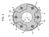
- the in the FIGS. 1 and 2 Shaft coupling shown is designed as a flexible all-steel shaft coupling. It has a first, drive-side hub 1 and a second, output-side hub 1 ', wherein the hubs 1, 1' in each case via an associated disk set 2 with a connecting flange 3.1 torsionally rigid and are connected axially and angularly movable.
- the connection flange 3.1 is an integral element of a sleeve-like section 3.2 and a second integral connection flange 3.3 having coupling element 3.
- Such coupling elements 3 are also referred to as D-flange.
- the two coupling elements (D-flanges) 3 are rotationally fixed to each other via the second connecting flanges 3.3 and an intermediate sleeve 18 by means of clamping bolts 4.
- the clamping bolts 4 are provided with collar nuts 5 hexagon-fitting screws. Due to the two pairs in a row connected plate packs 2 allows the shaft coupling according to Fig. 1 not only the compensation of an axial and angular offset, but also the compensation of a radial offset of the waves to be connected.
- the arranged between the coupling elements 3 intermediate sleeve 18 allows the radial mounting of the shaft coupling and bridges a greater distance between the waves to be connected.
- the Intermediate sleeve has for this purpose connection flanges 18.1, in which bore 19 are formed.
- the respective hub 1, 1 'of in Fig. 1 shaft coupling shown three evenly distributed over the circumference arranged wing-shaped hub flanges 1.1, which are integrally connected to the tubular hub portion 1.2 and projecting radially outwardly therefrom.
- the hubs 1, 1 'each have a conical seat surface 1.3 for producing a conical press connection with a correspondingly formed shaft.
- the shaft-hub connection can also be designed as keyway connection, cylindrical press connection or other customary shaft-hub connection.
- a conical press connection is preferred in the shaft coupling according to the invention.
- the hub 1, 1 'associated connection flange 3.1 has a number of hub flanges 1.1 corresponding number of recesses 3.4, in which the wing-shaped hub flanges 1.1 are recorded with a play S form fit.
- the clearance S between the respective circumferentially facing edge of the hub flange 1.1 and the connecting flange 3.1 each about 0.44 mm or about 0.25 °.
- the mutually facing flanks of the hub flanges 1.1 and recesses 3.4 have flat stop surfaces 6, which define contact surfaces and lie in radial planes which intersect the longitudinal central axis M of the shaft coupling. Short-term overload torques are absorbed by positive locking, ie by contact of the facing abutment surfaces 6. An overload of the lamellar plates or laminations of the plate pack 2 is thereby prevented.
- the respective hub flange 1.1 On the outer circumference, the respective hub flange 1.1 has an arcuate end face 1.4, which extends over approximately 46 ° of the circumference. The transition from the flat stop surface 6 to the circular arc-shaped end face 1.4 is rounded. Furthermore, it can be seen that the connection flange 3.1 is provided with an annular collar or sheath 3.5, which surrounds the disk set 2 with play and this projects beyond in the axial direction. In the event of a finned fracture, fragments which would be thrown off due to centrifugal force are retained by the jacket (collar) 3.5.
- the disk set 2 connected to the hub 1 is arranged on the drive side facing side of the hub flange 1.1, while the disk set 2, which is connected to the output side hub 1 ', on the output side facing side of the hub flange 1.1 is arranged.
- the center of gravity of the shaft coupling is thus relatively close to the shaft bearings. As a result, the amplitude of vibrations that usually occur due to imbalances in rotation of the overhanging waves is minimized.
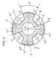
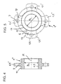
- the hub 1 '' according to the in the FIGS. 3 to 8 illustrated embodiment four evenly distributed over the circumference arranged hub flanges 1.1 'on.
- a corresponding number of recesses 3.4 ' are formed in the connecting flange 3.1' associated with the hub 1 ', in which the hub flanges 1.1' are positively received with play S.
- the clearance S between the abutment surfaces 6 defining the flat contact surfaces amounts to approximately 0, 35 mm or approx. 0.2 °.
- planar contact surfaces 6 of the wing-shaped hub flanges 1.1 lie in radial planes extending through the axis of rotation or longitudinal center axis M of the hub or shaft coupling. This is in Fig. 3 illustrated by a the center or the longitudinal center axis M intersecting straight line G.
- the bores 10 serve to fix the disk packs 2 when balancing the shaft coupling 2 for the transport of the shaft coupling.
- the flat contact surfaces 6 of the respective hub flange 1.1 ' include an angle ⁇ of about 44.8 °. Between the flat contact surfaces 6 and the cylindrical surface 11 of the hub 1 '' is a continuous, rounded throat region 12 is formed in each case. It can also be seen that the plane Contact surfaces 6 of the respective hub flange 1.1 'to the outer periphery of flat flank portions 13 connect, which are angled relative to the flat contact surfaces 6 and at the respective hub flange 1.1' parallel to each other. These rectilinear flank regions 13 then go rounded into the outer circular arc-shaped peripheral regions 1.4 of the respective hub flange 1.1 '.
- the recesses 3.4 'for the positive reception of the hub flanges 1.1' in the connection flange 3.1 ' have flared regions 14 in the region facing the flat flank regions 13 of the hub flanges 1.1' and flank regions 15 tapered in the region facing the rounded flank regions 12 of the hub flanges 1.1 '. This ensures that there is no contact between the hub 1 "and the connection flange 3.1 'in the fillet regions 12 and 14 during operation of the shaft coupling, even if the mutually facing flat stop surfaces (contact surfaces) 6 of FIG Hub flanges 1.1 'and the connecting flange 3.1' due to overloading of the plate package 2 touch.
- the embodiment of the invention is not limited to the embodiments described above. Rather, a variety of variants and modifications are possible that make use of the invention set forth in the claims even with fundamentally different design. So it is also within the scope of the invention, when the substantially planar stop surfaces. 6 the hub flanges 1.1, 1.1 'lie in radial planes which do not intersect the longitudinal center axis M or axis of rotation of the shaft coupling but lie in planes which intersect at least the shaft carrying the hub 1, 1', 1 "or lie in planes whose distance to the axis of rotation or longitudinal center axis M of the shaft coupling is less than a quarter, preferably less than one fifth of the inner diameter D i of the tubular portion of the hub 1, 1 ', 1''.
Landscapes
- Engineering & Computer Science (AREA)
- General Engineering & Computer Science (AREA)
- Mechanical Engineering (AREA)
- Mutual Connection Of Rods And Tubes (AREA)
- Mechanical Operated Clutches (AREA)
- Pivots And Pivotal Connections (AREA)
- Handcart (AREA)
- Clamps And Clips (AREA)
- Storage Of Web-Like Or Filamentary Materials (AREA)
- Packaging Of Annular Or Rod-Shaped Articles, Wearing Apparel, Cassettes, Or The Like (AREA)
Description
- Die Erfindung betrifft eine flexible Wellenkupplung mit mindestens einer Nabe und mindestens einem Anschlussflansch, wobei die mindestens eine Nabe und der mindestens eine Anschlussflansch über ein Lamellenpaket, das mittels umfangsmäßig verteilt angeordneter Spannbolzen wechselweise an dem Anschlussflansch und der Nabe befestigt ist, drehsteif und axial- sowie winkelbeweglich miteinander verbunden sind, und wobei die mindestens eine Nabe einen rohrförmigen Abschnitt zur Aufnahme einer Welle aufweist.
- Zum Stand der Technik gehören flexible Wellenkupplungen, deren beide jeweils einen Anschlussflansch aufweisende Kupplungshälften über ein Lamellenpaket, das mittels umfangsmäßig verteilt angeordneten Spannbolzen wechselweise an den beiden Anschlussflanschen befestigt ist, drehsteif und axial- und winkelbeweglich miteinander verbunden sind (siehe z.B.
DE 34 43 485 A1 undEP 0771960 ). - Solche Kupplungen werden zur Übertragung von Drehmomenten einzeln oder auch paarweise hintereinander geschaltet eingesetzt. Als Einzelkupplung lässt sie einen Winkel-und Axialversatz und als Kupplungspaar zudem einen Radialversatz (Parallelversatz) der zu verbindenden Wellen zu. Das Lamellenpaket solcher Kupplungen setzt sich aus einzelnen Lamellenlaschen oder aus Lamellenringen zusammen. Die Lamellenlaschen bzw. Lamellenringe sind während der Rotation der verbundenen Wellen einer wechselnden, von der Größe des Winkel- oder Radialversatzes der Wellen abhängigen Biegebeanspruchung unterworfen. Mitunter kommt es bei hohen Drehzahlen der Wellen infolge der mit hoher Frequenz wechselnden Biegebeanspruchung zu einem Lamellenbruch.
- Es sind verschiedene Maßnahmen bekannt, die geeignet sind, einen Lamellenbruch zu vermeiden. Diesbezüglich wurden spezielle Lamellenwerkstoffe sowie optimierte geometrische Formen für die Lamellen entwickelt. Häufig werden die Lamellenpakete derartiger Wellenkupplungen aber einfach überdimensioniert, um eine hohe Sicherheit gegen Lamellenbruch zu erzielen, was jedoch hinsichtlich der Herstellungskosten der Wellenkupplungen unbefriedigend ist.
- Auch wurden flexible Lamellenpaket-Wellenkupplungen entwickelt, die Formschlusselemente aufweisen, welche eine Überlastung des Lamellenpakets bzw. bei Lamellenbruch eine Unterbrechung der drehstarren Wellenverbindung verhindern. Eine solche Kupplung ist aus der
EP 0 191 552 A2 bekannt. Die Nabe der dort dargestellten Kupplung weist einen radial abstehenden Nabenflansch auf, der ähnlich einem gleichseitigen Dreieck ausgebildet ist, wobei die Ecken des im wesentlichen dreieckigen Nabenflansches stumpf abgeflacht sind. Der Nabenflansch ist in einer entsprechend ausgebildeten Ausnehmung eines Hülsenflansches formschlüssig aufgenommen. Der Nabenflansch und der Hülsenflansch sind über ein Lamellenpaket, das mittels umfangsmäßig verteilt angeordneten Spannbolzen wechselweise an dem Nabenflansch und dem Hülsenflansch befestigt ist, drehsteif und axial- und winkelbeweglich miteinander verbunden. - Der vorliegenden Erfindung liegt die Aufgabe zugrunde, eine Wellenkupplung der eingangs genannten Art bereitzustellen, die einen optimierten Überlastschutz bietet.
- Diese Aufgabe wird durch eine Wellenkupplung mit den Merkmalen des Anspruchs 1 gelöst.
- Die Nabe der erfindungsgemäßen Wellenkupplung weist mehrere flügelartig ausgebildete Nabenflansche auf, die einstückig mit dem rohrförmigen Abschnitt der Nabe verbunden sind und davon radial nach außen abstehen und in einer entsprechenden Anzahl von Ausnehmungen des Anschlussflansches mit Spiel formschlüssig aufgenommen sind, wobei einander zugewandte Flanken der Nabenflansche und Ausnehmungen im Wesentlichen eben ausgebildete Anschlagflächen umfassen, die Kontaktflächen definieren und in Ebenen liegen, welche die die Nabe tragende Welle schneiden.
- Durch die erfindungsgemäße Gestaltung des Nabenflansches und des Anschlussflansches lassen sich relativ große Anschlagflächen als Kontaktfläche erzielen, die bei Überlastung des Lamellenpakets oder gar einem Lamellenbruch das herrschende Drehmoment mit entsprechend geringer Flächenpressung zwischen Nabenflansch und Anschlussflansch übertragen. Die radiale Erstreckung der jeweiligen ebenen Kontaktfläche ist vorzugsweise größer/gleich der axialen Breite des Nabenflansches. Eine punktförmige oder stark konzentrierte Flächenpressung zwischen Nabenflansch und Anschlussflansch (Hülsenflansch), wie sie bei der aus der
EP 0 191 552 A2 bekannten Wellenkupplung im Falle einer Überlastung des Lamellenpakets oder eines Lamellenbruch auftritt, wird somit bei der erfindungsgemäßen Wellenkupplung vermieden. - Vorzugsweise liegen die im Wesentlichen eben ausgebildeten Anschlagflächen der Nabenflansche in Ebenen, deren Abstand zur Drehachse oder Längsmittelachse der Wellenkupplung weniger als ein Viertel, vorzugsweise weniger als ein Fünftel des mittleren Innendurchmessers des die Welle aufnehmenden rohrförmigen Abschnitts der Nabe beträgt.
- Eine besonders bevorzugte Ausgestaltung der erfindungsgemäßen Wellenkupplung ist dadurch gekennzeichnet, dass die im Wesentlichen eben ausgebildeten Anschlagflächen im Wesentlichen in Radialebenen liegen, welche die Längsmittelachse bzw. Drehachse der Wellenkupplung schneiden. Mit dieser Ausgestaltung lässt sich hinsichtlich des Überlastschutzes des Lamellenpakets außer einer relativ großen Kontaktfläche zugleich erreichen, dass die bei einem Kontakt der Flanken von Nabenflansch und Anschlussflansch zu übertragende Kraft im wesentlichen senkrecht auf die lastaufnehmende Flanke (Kontaktfläche) einwirkt. Ein materialverschleißender Schlupf zwischen den Kontaktflächen (Flanken) wird somit vermieden.
- Das Spiel zwischen den Anschlagflächen der einander zugewandten Flanken von Nabenflansch und Anschlussflansch liegt vorzugsweise im Bereich von 0,25 mm und 1,0 mm.
- Weitere bevorzugte und vorteilhafte Ausgestaltungen der erfindungsgemäßen Wellenkupplung sind in den Unteransprüchen angegeben.
- Nachfolgend wird die Erfindung anhand einer zwei Ausführungsbeispiele darstellenden Zeichnung näher erläutert. Es zeigen:
- Fig. 1
- eine Längsschnittansicht einer erfindungsgemäßen Wellenkupplung;
- Fig. 2
- eine Querschnittansicht der Wellenkupplung entlang der Schnittlinie A-A der
Fig. 1 ; - Fig. 3
- eine Querschnittansicht einer erfindungsgemäßen Wellenkupplung nach einem zweiten Ausführungs- beispiel;
- Fig. 4
- eine Längsschnittansicht der Nabe der Wellen- kupplung der
Fig. 3 ; - Fig. 5
- die Nabe der Wellenkupplung der
Fig. 3 in Quer- seitenansicht; - Fig. 6
- eine Querseitenansicht auf den Naben-Aufnahme- bereich des D-Flansches der Wellenkupplung der
Fig. 3 (ohne Nabe); - Fig. 7
- eine Längsschnittansicht des D-Flansches der
Fig. 6 ; und - Fig. 8
- eine Querseitenansicht des D-Flansches der
Fig. 6 auf die dem Naben-Aufnahmebereich gegenüberliegende Seite. - Die in den
Figuren 1 und2 dargestellte Wellenkupplung ist als flexible Ganzstahl-Wellenkupplung ausgebildet. Sie weist eine erste, antriebsseitige Nabe 1 und eine zweite, abtriebsseitige Nabe 1' auf, wobei die Naben 1, 1' jeweils über ein zugeordnetes Lamellenpaket 2 mit einem Anschlussflansch 3.1 drehstarr und axial- sowie winkelbeweglich verbunden sind. Der Anschlussflansch 3.1 ist integrales Element eines einen hülsenartigen Abschnitt 3.2 und einen zweiten integralen Anschlussflansch 3.3 aufweisenden Kupplungselements 3. Derartige Kupplungselemente 3 werden auch als D-Flansch bezeichnet. - Die beiden Kupplungselemente (D-Flansche) 3 sind über die zweiten Anschlussflansche 3.3 und eine Zwischenhülse 18 mittels Spannbolzen 4 drehstarr miteinander verbunden. Bei den Spannbolzen 4 handelt es sich um mit Bundmuttern 5 versehene Sechskant-Passschrauben. Aufgrund der beiden paarweise hintereinander geschalteten Lamellenpakete 2 ermöglicht die Wellenkupplung gemäß
Fig. 1 nicht nur den Ausgleich eines Axial- sowie Winkelversatzes, sondern zusätzlich auch den Ausgleich eines Radialversatzes der zu verbindenden Wellen. Die zwischen den Kupplungselementen 3 angeordnete Zwischenhülse 18 ermöglicht die radiale Montage der Wellenkupplung und überbrückt einen größeren Abstand zwischen den zu verbindenden Wellen. Die Zwischenhülse weist hierzu Anschlussflansche 18.1 auf, in denen Bohrung 19 ausgebildet sind. - Wie in
Fig. 2 gezeigt, weist die jeweilige Nabe 1, 1' der inFig. 1 dargestellten Wellenkupplung drei gleichmäßig über den Umfang verteilt angeordnete flügelförmige Nabenflansche 1.1 auf, die mit dem rohrförmigen Nabenabschnitt 1.2 einstückig verbunden sind und davon radial nach außen abstehen. Die Naben 1, 1' weisen jeweils eine Konussitzfläche 1.3 zur Herstellung einer konischen Pressverbindung mit einer entsprechend ausgebildeten Welle auf. Alternativ kann die Welle-Nabe-Verbindung auch als Passfederverbindung, zylindrische Pressverbindung oder sonstige übliche Welle-Nabe-Verbindung ausgeführt sein. Eine konische Pressverbindung ist bei der erfindungsgemäßen Wellenkupplung jedoch bevorzugt. - Der der Nabe 1, 1' zugeordnete Anschlussflansch 3.1 weist eine der Anzahl der Nabenflansche 1.1 entsprechende Anzahl von Ausnehmungen 3.4 auf, in denen die flügelförmigen Nabenflansche 1.1 mit Spiel S formschlüssig aufgenommen sind. In dem in
Fig. 2 dargestellten Ausführungsbeispiel beträgt das Spiel S zwischen der jeweiligen in Umfangsrichtung weisenden Flanke des Nabenflansches 1.1 und dem Anschlussflansch 3.1 jeweils etwa 0,44 mm bzw. etwa 0,25°. Die einander zugewandten Flanken der Nabenflansche 1.1 und Ausnehmungen 3.4 weisen eben ausgebildete Anschlagflächen 6 auf, die Kontaktflächen definieren und in Radialebenen liegen, welche die Längsmittelachse M der Wellenkupplung schneiden. Kurzfristige Überlastmomente werden durch Formschluss, d.h. durch Kontakt der einander zugewandten Anschlagflächen 6 aufgenommen. Eine Überlastung der Lamellenlaschen oder Lamellenringe des Lamellenpakets 2 wird hierdurch verhindert. - Am Außenumfang weist der jeweilige Nabenflansch 1.1 eine kreisbogenförmige Stirnfläche 1.4 auf, die sich über etwa 46° des Kreisumfangs erstreckt. Der Übergang von der ebenen Anschlagfläche 6 zu der kreisbogenförmigen Stirnfläche 1.4 ist abgerundet ausgebildet. Ferner ist zu erkennen, dass der Anschlussflansch 3.1 mit einem kreisringförmigen Kragen oder Mantel 3.5 versehen ist, der das Lamellenpaket 2 mit Spiel umgibt und dieses in axialer Richtung überragt. Bei einem eventuellen Lamellenbruch werden Bruchstücke, die aufgrund der Zentrifugalkraft weggeschleudert werden würden, durch den Mantel (Kragen) 3.5 zurückgehalten.
- Das mit der Nabe 1 verbundene Lamellenpaket 2 ist auf der der Antriebsseite zugewandten Seite des Nabenflansches 1.1 angeordnet, während das Lamellenpaket 2, welches mit der abtriebsseitigen Nabe 1' verbunden ist, auf der der Abtriebsseite zugewandten Seite des Nabenflansches 1.1 angeordnet ist. Der Schwerpunkt der Wellenkupplung liegt somit relativ nahe an den Wellenlagern. Hierdurch wird die Amplitude von Schwingungen, die bei Rotation der überhängenden Wellen üblicherweise aufgrund von Unwuchten auftreten, minimiert.
- Im Unterscheid zu dem Ausführungsbeispiel gemäß den
Figuren 1 und2 weist die Nabe 1'' gemäß dem in denFiguren 3 bis 8 dargestellten Ausführungsbeispiel vier gleichmäßig über den Umfang verteilt angeordnete Nabenflansche 1.1' auf. In dem der Nabe 1" zugeordneten Anschlussflansch 3.1' ist wiederum eine entsprechende Anzahl von Ausnehmungen 3.4' ausgebildet, in denen die Nabenflansche 1.1' mit Spiel S formschlüssig aufgenommen sind. Das Spiel S zwischen den ebene Kontaktflächen definierenden Anschlagflächen 6 beträgt hier ca. 0,35 mm bzw. ca. 0,2°. - Es ist zu erkennen, dass die ebenen Kontaktflächen 6 der flügelförmigen Nabenflansche 1.1' in durch die Drehachse bzw. Längsmittelachse M der Nabe bzw. Wellenkupplung verlaufenden Radialebenen liegen. Dies ist in
Fig. 3 anhand einer den Mittelpunkt bzw. die Längsmittelachse M schneidenden Geraden G verdeutlicht. - Mit 7 und 8 sind die der Befestigung der Spannbolzen 9 dienen Bohrungen der Nabe 1" bzw. des zugeordneten Anschlussflansches 3.1' bezeichnet. Die Bohrungen 10 dienen der Fixierung der Lamellenpakete 2 bei einer Auswuchtung der Wellenkupplung. Ferner dienen diese Bohrungen 10 der Fixierung der Lamellenpakete 2 für den Transport der Wellenkupplung.
- In dem in
Fig. 3 dargestellten Ausführungsbeispiel schließen die ebenen Kontaktflächen 6 des jeweiligen Nabenflansches 1.1' einen Winkel α von ca. 44,8° ein. Zwischen den ebenen Kontaktflächen 6 und der zylindrischen Mantelfläche 11 der Nabe 1'' ist jeweils ein stufenloser, gerundeter Kehlbereich 12 ausgebildet. Ferner ist zu erkennen, dass sich an die ebenen Kontaktflächen 6 des jeweiligen Nabenflansches 1.1' zum Außenumfang hin ebene Flankenbereiche 13 anschließen, die gegenüber den ebenen Kontaktflächen 6 abgewinkelt sind und an dem jeweiligen Nabenflansch 1.1' parallel zueinander verlaufen. Diese geradlinigen Flankenbereiche 13 gehen dann abgerundet in die äußeren kreisbogenförmigen Umfangsbereiche 1.4 des jeweiligen Nabenflansches 1.1' über. - Die Ausnehmungen 3.4' zur formschlüssigen Aufnahme der Nabenflansche 1.1' im Anschlussflansch 3.1' weisen dagegen in dem den ebenen Flankenbereichen 13 der Nabenflansche 1.1' zugewandten Bereich gerundete Kehlbereiche 14 und in dem den gerundeten Kehlbereichen 12 der Nabenflansche 1.1' zugewandten Bereich abgeschrägte Flankenbereiche 15 auf. Hierdurch ist sichergestellt, dass es in den Kehlbereichen 12 und 14 während des Betriebes der Wellenkupplung zu keinem Kontakt zwischen der Nabe 1" und dem Anschlussflansch 3.1' kommt, und zwar auch dann nicht, wenn sich die einander zugewandten ebenen Anschlagflächen (Kontaktflächen) 6 der Nabenflansche 1.1' und des Anschlussflansches 3.1' infolge einer Überlastung des Lamellenpakets 2 berühren.
- Die Ausführung der Erfindung ist nicht auf die vorstehend beschriebenen Ausführungsbeispiele beschränkt. Vielmehr sind eine Vielzahl von Varianten und Modifikationen möglich, die auch bei grundsätzlich abweichender Gestaltung von der in den Ansprüchen dargelegten Erfindung Gebrauch machen. So liegt es auch im Rahmen der Erfindung, wenn die im Wesentlichen eben ausgebildeten Anschlagflächen 6 der Nabenflansche 1.1, 1.1' in Radialebenen liegen, welche die Längsmittelachse M bzw. Drehachse der Wellenkupplung nicht schneiden, sondern in Ebenen liegen, welche zumindest die die Nabe 1, 1', 1" tragende Welle schneiden, oder in Ebenen liegen, deren Abstand zur Drehachse oder Längsmittelachse M der Wellenkupplung weniger als ein Viertel, vorzugsweise weniger als ein Fünftel des Innendurchmessers Di des rohrförmigen Abschnitts der Nabe 1, 1', 1'' beträgt.
-
- 1
- Nabe
- 1'
- Nabe
- 1"
- Nabe
- 1.1
- Nabenflansch
- 1.1'
- Nabenflansch
- 1.2
- rohrförmigen Nabenabschnitt
- 1.3
- Kegelsitzfläche der Nabe
- 1.4
- Stirnfläche/kreisbogenförmiger Umfangsbereich des Nabenflansches
- 2
- Lamellenpaket
- 3
- Kupplungselement (D-Flansch)
- 3'
- Kupplungselement (D-Flansch)
- 3.1
- (erster) Anschlussflansch
- 3.1'
- (erster) Anschlussflansch
- 3.2
- hülsenartiger Abschnitt des D-Flansches
- 3.3
- zweiter Anschlussflansch
- 3.4
- Ausnehmung
- 3.4'
- Ausnehmung
- 3.5
- Kragen (Mantel)
- 4
- Spannbolzen
- 5
- Bundmutter
- 6
- ebene Anschlagfläche (Kontaktfläche)
- 7
- Bohrung
- 8
- Bohrung
- 9
- Spannbolzen
- 10
- Bohrung
- 11
- Mantelfläche der Nabe
- 12
- Kehlbereich des Nabenflansches
- 13
- ebener Flankenbereich des Nabenflansches
- 14
- Kehlbereich der Anschlussflanschausnehmung
- 15
- abgeschrägter Flankenbereich des Anschlussflansches
- 16
- Bohrung
- 17
- Bohrung
- 18
- Zwischenhülse
- 18.1
- Anschlussflansch(e) der Zwischenhülse
- 19
- Bohrung
- Di
- Innendurchmesser
- G
- Gerade
- M
- Längsmittelachse (Drehachse)
- S
- Spiel
- α
- Winkel
Claims (12)
- Flexible Wellenkupplung mit mindestens einer Nabe und mindestens einem Anschlussflansch, wobei die mindestens eine Nabe (1, 1', 1") und der mindestens eine Anschlussflansch (3.1, 3.1') über ein Lamellenpaket (2), das mittels umfangsmäßig verteilt angeordneten Spannbolzen (9) wechselweise an dem Anschlussflansch (3.1, 3.1') und der Nabe (1, 1', 1") befestigt ist, drehsteif und axial- sowie winkelbeweglich miteinander verbunden sind, und wobei die mindestens eine Nabe (1, 1', 1") einen rohrförmigen Abschnitt (1.2) zur Aufnahme einer Welle aufweist, wobei
die Nabe mehrere flügelartig ausgebildete Nabenflansche (1.1, 1.1') aufweist, die einstückig mit dem rohrförmigen Abschnitt (1.2) verbunden sind und davon radial nach außen abstehen, wobei der Anschlussflansch eine entsprechende Anzahl von Ausnehmungen (3.4, 3.4') aufweist, in denen die Nabenflansche (1.1, 1.1') mit Spiel (S) formschlüssig aufgenommen sind, wobei einander zugewandte Flanken der Nabenflansche (1.1, 1.1') und Ausnehmungen (3.4, 3.4') im Wesentlichen eben ausgebildete Anschlagflächen (6) umfassen, die Kontaktflächen definieren, dadurch gekennzeichnet, dass die Kontaktflächen in Ebenen liegen, welche die die mindestens eine Nabe (1, 1', 1") tragende Welle schneiden. - Wellenkupplung nach Anspruch 1,
dadurch gekennzeichnet, dass die im Wesentlichen eben ausgebildeten Anschlagflächen (6) in Ebenen liegen, deren Abstand zur Drehachse oder Längsmittelachse (M) der Wellenkupplung weniger als ein Viertel, vorzugsweise weniger als ein Fünftel des Innendurchmessers (Di) des rohrförmigen Abschnitts (1.2) der Nabe (1, 1', 1") beträgt. - Wellenkupplung nach Anspruch 1,
dadurch gekennzeichnet, dass die im Wesentlichen eben ausgebildeten Anschlagflächen (6) im Wesentlichen in die Längsmittelachse (M) der Wellenkupplung schneidenden Radialebenen liegen. - Wellenkupplung nach einem der Ansprüche 1 bis 3,
dadurch gekennzeichnet, dass die radiale Erstreckung der jeweiligen Kontaktfläche prober/gleich der axialen Breite des Nabenflansches (1.1, 1.1') ist. - Wellenkupplung nach einem der Ansprüche 1 bis 4,
dadurch gekennzeichnet, dass die Nabe (1, 1') drei gleichmäßig über den Umfang verteilt angeordnete Nabenflansche (1.1) aufweist. - Wellenkupplung nach einem der Ansprüche 1 bis 4,
dadurch gekennzeichnet, dass die Nabe (1") vier gleichmäßig über den Umfang verteilt angeordnete Nabenflansche (1.1') aufweist. - Wellenkupplung nach einem der Ansprüche 1 bis 6,
dadurch gekennzeichnet, dass das Spiel (S) zwischen den Anschlagflächen (6) im Bereich von 0,25 mm und 1,0 mm liegt. - Wellenkupplung nach einem der Ansprüche 1 bis 7,
dadurch gekennzeichnet, dass diese eine erste, einer Antriebswelle zugeordnete Nabe (1) und eine zweite, einer Abtriebswelle zugeordnete Nabe (1') aufweist, wobei die beiden Naben jeweils über ein zugeordnetes Lamellenpaket (2) mit einem Anschlussflansch (3.1) drehstarr und axial- sowie winkelbeweglich verbunden sind, wobei die beiden Anschlussflansche (3.1) jeweils integrales Element eines einen zweiten integralen Anschlussflansch (3.3) und einen hülsenartigen Abschnitt (3.2) aufweisenden Kupplungselements (3) sind, und wobei die beiden Kupplungselemente (3) über eine zwischen den zweiten Anschlussflanschen (3.3) angeordnete Zwischenhülse (18) mittels Spannbolzen (4) drehstarr miteinander verbunden sind. - Wellenkupplung nach Anspruch 8,
dadurch gekennzeichnet, dass das jeweilige Lamellenpaket (2) auf der Seite des Nabenflansches (1.1, 1.1') angeordnet ist, die dem Wellenlager der die zugehörige Nabe (1, 1', 1") tragenden Welle zugewandt ist. - Wellenkupplung nach einem der Ansprüche 1 bis 9,
dadurch gekennzeichnet, dass die Nabe oder Naben (1, 1', 1") jeweils eine Konussitzfläche (1.3) zur Herstellung einer konischen Pressverbindung mit einer entsprechend ausgebildeten Welle aufweisen. - Wellenkupplung nach einem der Ansprüche 1 bis 9,
dadurch gekennzeichnet, dass die Nabe oder Naben (1) jeweils eine zylindrische Sitzfläche zur Herstellung einer zylindrischen Pressverbindung mit einer entsprechend ausgebildeten Welle aufweisen. - Wellenkupplung nach einem der Ansprüche 1 bis 9,
dadurch gekennzeichnet, dass die Nabe order Naben (1) mindestens eine Ausnehmung zur formschlüssigen Aufnahme einer Passfeder aufweist.
Applications Claiming Priority (1)
| Application Number | Priority Date | Filing Date | Title |
|---|---|---|---|
| DE102007035199A DE102007035199A1 (de) | 2007-07-25 | 2007-07-25 | Flexible Wellenkupplung mit Lamellenpaket und Formschlusselementen |
Publications (3)
| Publication Number | Publication Date |
|---|---|
| EP2019222A2 EP2019222A2 (de) | 2009-01-28 |
| EP2019222A3 EP2019222A3 (de) | 2009-06-03 |
| EP2019222B1 true EP2019222B1 (de) | 2011-02-23 |
Family
ID=39879095
Family Applications (1)
| Application Number | Title | Priority Date | Filing Date |
|---|---|---|---|
| EP08104681A Active EP2019222B1 (de) | 2007-07-25 | 2008-07-09 | Flexible Wellenkupplung mit Lamellenpaket und Formschlusselementen |
Country Status (4)
| Country | Link |
|---|---|
| EP (1) | EP2019222B1 (de) |
| AT (1) | ATE499536T1 (de) |
| DE (2) | DE102007035199A1 (de) |
| ES (1) | ES2361788T3 (de) |
Family Cites Families (5)
| Publication number | Priority date | Publication date | Assignee | Title |
|---|---|---|---|---|
| US3834182A (en) * | 1973-01-22 | 1974-09-10 | Riggers Mfg Co | Floating ring coupler |
| DE3443485A1 (de) | 1984-11-29 | 1986-06-05 | ATEC-Weiss KG, 4426 Vreden | Flexible ganzstahl-kupplung |
| EP0191552A3 (de) | 1985-01-17 | 1987-07-15 | Koppers Company, Inc. | Elastische Kupplung |
| CA2128982A1 (en) * | 1993-07-28 | 1995-01-29 | Sadatomo Kuribayashi | Shaft coupling |
| US7559845B2 (en) * | 2005-10-07 | 2009-07-14 | Rexnord Industries, Llc | Nested disc pack coupling |
-
2007
- 2007-07-25 DE DE102007035199A patent/DE102007035199A1/de not_active Withdrawn
-
2008
- 2008-07-09 EP EP08104681A patent/EP2019222B1/de active Active
- 2008-07-09 DE DE502008002651T patent/DE502008002651D1/de active Active
- 2008-07-09 ES ES08104681T patent/ES2361788T3/es active Active
- 2008-07-09 AT AT08104681T patent/ATE499536T1/de active
Also Published As
| Publication number | Publication date |
|---|---|
| ES2361788T3 (es) | 2011-06-22 |
| DE502008002651D1 (de) | 2011-04-07 |
| EP2019222A2 (de) | 2009-01-28 |
| DE102007035199A1 (de) | 2009-02-05 |
| EP2019222A3 (de) | 2009-06-03 |
| ATE499536T1 (de) | 2011-03-15 |
Similar Documents
| Publication | Publication Date | Title |
|---|---|---|
| EP2363301B1 (de) | Stirnverzahnung für eine antreibbare Radnabe | |
| DE19709950B4 (de) | Drehsteife, biegeelastische Wellenkupplung, insbesondere aus Ganzstahl | |
| DE3417555C2 (de) | ||
| DE2755131C2 (de) | Kupplung zum starren Verbinden zweier gleichachsiger und zum Übertragen von Drehmoment geeigneter Maschinenteile | |
| EP1178232B1 (de) | Flanschmitnehmer für ein Kardangelenk und Gelenkwelle | |
| DE3314322A1 (de) | Kreuzgelenk fuer eine gelenkwelle | |
| EP2019222B1 (de) | Flexible Wellenkupplung mit Lamellenpaket und Formschlusselementen | |
| DE2422639A1 (de) | Elastische kupplung | |
| DE102005024452B4 (de) | Differentialanordnung mit Montageöffnungen | |
| EP1723345B1 (de) | Kreuzgelenkanordnung | |
| EP1683980B1 (de) | Flanschmitnehmer für ein Kardangelenk und Gelenkwelle | |
| EP1234990B1 (de) | Schalenkupplung zur drehfesten Verbindung von Wellen | |
| EP3293407B1 (de) | Welle-nabe-verbindung | |
| DE2100052B2 (de) | Elastische Kupplung | |
| DE202019106972U1 (de) | Reibschlüssige Welle-Nabe-Verbindung | |
| EP1530685B1 (de) | Anschlusselement zur verbindung von gelenkspindeln mit anschlussaggregaten, insbesondere trefferhalterung mit konischer zentrierung | |
| DE102004017104A1 (de) | Kreuzgelenkanordnung | |
| DE202005021961U1 (de) | Stirnverzahnung für eine antreibbare Radnabe | |
| EP2230414B1 (de) | Feste, flexible Kupplung zur Drehmomentübertragung | |
| DE2604317C3 (de) | Flanschkupplung, insbesondere Zuglaschenkupplung | |
| WO2023179906A1 (de) | Passfeder für welle-nabe-verbindung und welle-nabe-verbindung | |
| EP2422941B1 (de) | Messerscheibe mit eckenloser, aber nicht kreisrunder Mittenausnehmung | |
| DE102022119297A1 (de) | Drehschwingungsdämpfersystem für einen Antriebsstrang sowie Antriebsstrang | |
| DE3312310C2 (de) | ||
| DE2363956C3 (de) | Elastische Wellenkupplung |
Legal Events
| Date | Code | Title | Description |
|---|---|---|---|
| PUAI | Public reference made under article 153(3) epc to a published international application that has entered the european phase |
Free format text: ORIGINAL CODE: 0009012 |
|
| AK | Designated contracting states |
Kind code of ref document: A2 Designated state(s): AT BE BG CH CY CZ DE DK EE ES FI FR GB GR HR HU IE IS IT LI LT LU LV MC MT NL NO PL PT RO SE SI SK TR |
|
| AX | Request for extension of the european patent |
Extension state: AL BA MK RS |
|
| PUAL | Search report despatched |
Free format text: ORIGINAL CODE: 0009013 |
|
| AK | Designated contracting states |
Kind code of ref document: A3 Designated state(s): AT BE BG CH CY CZ DE DK EE ES FI FR GB GR HR HU IE IS IT LI LT LU LV MC MT NL NO PL PT RO SE SI SK TR |
|
| AX | Request for extension of the european patent |
Extension state: AL BA MK RS |
|
| 17P | Request for examination filed |
Effective date: 20090713 |
|
| AKX | Designation fees paid |
Designated state(s): AT BE BG CH CY CZ DE DK EE ES FI FR GB GR HR HU IE IS IT LI LT LU LV MC MT NL NO PL PT RO SE SI SK TR |
|
| GRAP | Despatch of communication of intention to grant a patent |
Free format text: ORIGINAL CODE: EPIDOSNIGR1 |
|
| RIN1 | Information on inventor provided before grant (corrected) |
Inventor name: WEISS, RUDOLF Inventor name: MILLET, PATRICE DR. Inventor name: UHLEN, STEFAN |
|
| RAP1 | Party data changed (applicant data changed or rights of an application transferred) |
Owner name: SIEMENS AKTIENGESELLSCHAFT |
|
| GRAS | Grant fee paid |
Free format text: ORIGINAL CODE: EPIDOSNIGR3 |
|
| GRAA | (expected) grant |
Free format text: ORIGINAL CODE: 0009210 |
|
| AK | Designated contracting states |
Kind code of ref document: B1 Designated state(s): AT BE BG CH CY CZ DE DK EE ES FI FR GB GR HR HU IE IS IT LI LT LU LV MC MT NL NO PL PT RO SE SI SK TR |
|
| REG | Reference to a national code |
Ref country code: GB Ref legal event code: FG4D Free format text: NOT ENGLISH |
|
| REG | Reference to a national code |
Ref country code: CH Ref legal event code: EP |
|
| REG | Reference to a national code |
Ref country code: IE Ref legal event code: FG4D Free format text: LANGUAGE OF EP DOCUMENT: GERMAN |
|
| REF | Corresponds to: |
Ref document number: 502008002651 Country of ref document: DE Date of ref document: 20110407 Kind code of ref document: P |
|
| REG | Reference to a national code |
Ref country code: DE Ref legal event code: R096 Ref document number: 502008002651 Country of ref document: DE Effective date: 20110407 |
|
| REG | Reference to a national code |
Ref country code: NL Ref legal event code: VDEP Effective date: 20110223 Ref country code: ES Ref legal event code: FG2A Ref document number: 2361788 Country of ref document: ES Kind code of ref document: T3 Effective date: 20110622 |
|
| LTIE | Lt: invalidation of european patent or patent extension |
Effective date: 20110223 |
|
| PG25 | Lapsed in a contracting state [announced via postgrant information from national office to epo] |
Ref country code: LV Free format text: LAPSE BECAUSE OF FAILURE TO SUBMIT A TRANSLATION OF THE DESCRIPTION OR TO PAY THE FEE WITHIN THE PRESCRIBED TIME-LIMIT Effective date: 20110223 Ref country code: GR Free format text: LAPSE BECAUSE OF FAILURE TO SUBMIT A TRANSLATION OF THE DESCRIPTION OR TO PAY THE FEE WITHIN THE PRESCRIBED TIME-LIMIT Effective date: 20110524 Ref country code: HR Free format text: LAPSE BECAUSE OF FAILURE TO SUBMIT A TRANSLATION OF THE DESCRIPTION OR TO PAY THE FEE WITHIN THE PRESCRIBED TIME-LIMIT Effective date: 20110223 Ref country code: NO Free format text: LAPSE BECAUSE OF FAILURE TO SUBMIT A TRANSLATION OF THE DESCRIPTION OR TO PAY THE FEE WITHIN THE PRESCRIBED TIME-LIMIT Effective date: 20110523 Ref country code: LT Free format text: LAPSE BECAUSE OF FAILURE TO SUBMIT A TRANSLATION OF THE DESCRIPTION OR TO PAY THE FEE WITHIN THE PRESCRIBED TIME-LIMIT Effective date: 20110223 Ref country code: PT Free format text: LAPSE BECAUSE OF FAILURE TO SUBMIT A TRANSLATION OF THE DESCRIPTION OR TO PAY THE FEE WITHIN THE PRESCRIBED TIME-LIMIT Effective date: 20110623 Ref country code: SE Free format text: LAPSE BECAUSE OF FAILURE TO SUBMIT A TRANSLATION OF THE DESCRIPTION OR TO PAY THE FEE WITHIN THE PRESCRIBED TIME-LIMIT Effective date: 20110223 |
|
| PG25 | Lapsed in a contracting state [announced via postgrant information from national office to epo] |
Ref country code: SI Free format text: LAPSE BECAUSE OF FAILURE TO SUBMIT A TRANSLATION OF THE DESCRIPTION OR TO PAY THE FEE WITHIN THE PRESCRIBED TIME-LIMIT Effective date: 20110223 Ref country code: BG Free format text: LAPSE BECAUSE OF FAILURE TO SUBMIT A TRANSLATION OF THE DESCRIPTION OR TO PAY THE FEE WITHIN THE PRESCRIBED TIME-LIMIT Effective date: 20110523 Ref country code: FI Free format text: LAPSE BECAUSE OF FAILURE TO SUBMIT A TRANSLATION OF THE DESCRIPTION OR TO PAY THE FEE WITHIN THE PRESCRIBED TIME-LIMIT Effective date: 20110223 Ref country code: NL Free format text: LAPSE BECAUSE OF FAILURE TO SUBMIT A TRANSLATION OF THE DESCRIPTION OR TO PAY THE FEE WITHIN THE PRESCRIBED TIME-LIMIT Effective date: 20110223 Ref country code: CY Free format text: LAPSE BECAUSE OF FAILURE TO SUBMIT A TRANSLATION OF THE DESCRIPTION OR TO PAY THE FEE WITHIN THE PRESCRIBED TIME-LIMIT Effective date: 20110223 |
|
| REG | Reference to a national code |
Ref country code: IE Ref legal event code: FD4D |
|
| PG25 | Lapsed in a contracting state [announced via postgrant information from national office to epo] |
Ref country code: IE Free format text: LAPSE BECAUSE OF FAILURE TO SUBMIT A TRANSLATION OF THE DESCRIPTION OR TO PAY THE FEE WITHIN THE PRESCRIBED TIME-LIMIT Effective date: 20110223 Ref country code: DK Free format text: LAPSE BECAUSE OF FAILURE TO SUBMIT A TRANSLATION OF THE DESCRIPTION OR TO PAY THE FEE WITHIN THE PRESCRIBED TIME-LIMIT Effective date: 20110223 Ref country code: EE Free format text: LAPSE BECAUSE OF FAILURE TO SUBMIT A TRANSLATION OF THE DESCRIPTION OR TO PAY THE FEE WITHIN THE PRESCRIBED TIME-LIMIT Effective date: 20110223 |
|
| PG25 | Lapsed in a contracting state [announced via postgrant information from national office to epo] |
Ref country code: RO Free format text: LAPSE BECAUSE OF FAILURE TO SUBMIT A TRANSLATION OF THE DESCRIPTION OR TO PAY THE FEE WITHIN THE PRESCRIBED TIME-LIMIT Effective date: 20110223 Ref country code: SK Free format text: LAPSE BECAUSE OF FAILURE TO SUBMIT A TRANSLATION OF THE DESCRIPTION OR TO PAY THE FEE WITHIN THE PRESCRIBED TIME-LIMIT Effective date: 20110223 Ref country code: CZ Free format text: LAPSE BECAUSE OF FAILURE TO SUBMIT A TRANSLATION OF THE DESCRIPTION OR TO PAY THE FEE WITHIN THE PRESCRIBED TIME-LIMIT Effective date: 20110223 |
|
| PG25 | Lapsed in a contracting state [announced via postgrant information from national office to epo] |
Ref country code: MT Free format text: LAPSE BECAUSE OF FAILURE TO SUBMIT A TRANSLATION OF THE DESCRIPTION OR TO PAY THE FEE WITHIN THE PRESCRIBED TIME-LIMIT Effective date: 20110223 |
|
| PLBE | No opposition filed within time limit |
Free format text: ORIGINAL CODE: 0009261 |
|
| STAA | Information on the status of an ep patent application or granted ep patent |
Free format text: STATUS: NO OPPOSITION FILED WITHIN TIME LIMIT |
|
| BERE | Be: lapsed |
Owner name: SIEMENS A.G. Effective date: 20110731 |
|
| 26N | No opposition filed |
Effective date: 20111124 |
|
| PG25 | Lapsed in a contracting state [announced via postgrant information from national office to epo] |
Ref country code: PL Free format text: LAPSE BECAUSE OF FAILURE TO SUBMIT A TRANSLATION OF THE DESCRIPTION OR TO PAY THE FEE WITHIN THE PRESCRIBED TIME-LIMIT Effective date: 20110223 Ref country code: MC Free format text: LAPSE BECAUSE OF NON-PAYMENT OF DUE FEES Effective date: 20110731 |
|
| REG | Reference to a national code |
Ref country code: DE Ref legal event code: R097 Ref document number: 502008002651 Country of ref document: DE Effective date: 20111124 |
|
| PG25 | Lapsed in a contracting state [announced via postgrant information from national office to epo] |
Ref country code: BE Free format text: LAPSE BECAUSE OF NON-PAYMENT OF DUE FEES Effective date: 20110731 |
|
| REG | Reference to a national code |
Ref country code: CH Ref legal event code: PL |
|
| PG25 | Lapsed in a contracting state [announced via postgrant information from national office to epo] |
Ref country code: CH Free format text: LAPSE BECAUSE OF NON-PAYMENT OF DUE FEES Effective date: 20120731 Ref country code: LI Free format text: LAPSE BECAUSE OF NON-PAYMENT OF DUE FEES Effective date: 20120731 |
|
| PG25 | Lapsed in a contracting state [announced via postgrant information from national office to epo] |
Ref country code: LU Free format text: LAPSE BECAUSE OF NON-PAYMENT OF DUE FEES Effective date: 20110709 |
|
| PG25 | Lapsed in a contracting state [announced via postgrant information from national office to epo] |
Ref country code: IS Free format text: LAPSE BECAUSE OF FAILURE TO SUBMIT A TRANSLATION OF THE DESCRIPTION OR TO PAY THE FEE WITHIN THE PRESCRIBED TIME-LIMIT Effective date: 20110223 |
|
| PG25 | Lapsed in a contracting state [announced via postgrant information from national office to epo] |
Ref country code: TR Free format text: LAPSE BECAUSE OF FAILURE TO SUBMIT A TRANSLATION OF THE DESCRIPTION OR TO PAY THE FEE WITHIN THE PRESCRIBED TIME-LIMIT Effective date: 20110223 |
|
| PG25 | Lapsed in a contracting state [announced via postgrant information from national office to epo] |
Ref country code: HU Free format text: LAPSE BECAUSE OF FAILURE TO SUBMIT A TRANSLATION OF THE DESCRIPTION OR TO PAY THE FEE WITHIN THE PRESCRIBED TIME-LIMIT Effective date: 20110223 |
|
| REG | Reference to a national code |
Ref country code: AT Ref legal event code: MM01 Ref document number: 499536 Country of ref document: AT Kind code of ref document: T Effective date: 20130709 |
|
| PG25 | Lapsed in a contracting state [announced via postgrant information from national office to epo] |
Ref country code: AT Free format text: LAPSE BECAUSE OF NON-PAYMENT OF DUE FEES Effective date: 20130709 |
|
| REG | Reference to a national code |
Ref country code: FR Ref legal event code: PLFP Year of fee payment: 9 |
|
| REG | Reference to a national code |
Ref country code: FR Ref legal event code: PLFP Year of fee payment: 10 |
|
| REG | Reference to a national code |
Ref country code: DE Ref legal event code: R081 Ref document number: 502008002651 Country of ref document: DE Owner name: FLENDER GMBH, DE Free format text: FORMER OWNER: SIEMENS AKTIENGESELLSCHAFT, 80333 MUENCHEN, DE |
|
| REG | Reference to a national code |
Ref country code: ES Ref legal event code: PC2A Owner name: FLENDER GMBH Effective date: 20171219 |
|
| REG | Reference to a national code |
Ref country code: GB Ref legal event code: 732E Free format text: REGISTERED BETWEEN 20171207 AND 20171213 |
|
| REG | Reference to a national code |
Ref country code: FR Ref legal event code: TP Owner name: FLENDER GMBH, DE Effective date: 20180316 |
|
| REG | Reference to a national code |
Ref country code: FR Ref legal event code: PLFP Year of fee payment: 11 |
|
| REG | Reference to a national code |
Ref country code: DE Ref legal event code: R082 Ref document number: 502008002651 Country of ref document: DE Representative=s name: MICHALSKI HUETTERMANN & PARTNER PATENTANWAELTE, DE |
|
| PGFP | Annual fee paid to national office [announced via postgrant information from national office to epo] |
Ref country code: IT Payment date: 20220726 Year of fee payment: 15 Ref country code: GB Payment date: 20220721 Year of fee payment: 15 Ref country code: ES Payment date: 20220921 Year of fee payment: 15 |
|
| PGFP | Annual fee paid to national office [announced via postgrant information from national office to epo] |
Ref country code: FR Payment date: 20230725 Year of fee payment: 16 Ref country code: DE Payment date: 20230720 Year of fee payment: 16 |
|
| GBPC | Gb: european patent ceased through non-payment of renewal fee |
Effective date: 20230709 |
|
| PG25 | Lapsed in a contracting state [announced via postgrant information from national office to epo] |
Ref country code: GB Free format text: LAPSE BECAUSE OF NON-PAYMENT OF DUE FEES Effective date: 20230709 |