EP2362049A2 - Haushaltsgerät, insbesondere Garofen - Google Patents
Haushaltsgerät, insbesondere Garofen Download PDFInfo
- Publication number
- EP2362049A2 EP2362049A2 EP11152919A EP11152919A EP2362049A2 EP 2362049 A2 EP2362049 A2 EP 2362049A2 EP 11152919 A EP11152919 A EP 11152919A EP 11152919 A EP11152919 A EP 11152919A EP 2362049 A2 EP2362049 A2 EP 2362049A2
- Authority
- EP
- European Patent Office
- Prior art keywords
- hinge
- bearing
- hinge housing
- domestic appliance
- appliance according
- Prior art date
- Legal status (The legal status is an assumption and is not a legal conclusion. Google has not performed a legal analysis and makes no representation as to the accuracy of the status listed.)
- Granted
Links
- 238000010411 cooking Methods 0.000 title description 3
- 238000003780 insertion Methods 0.000 claims description 13
- 230000037431 insertion Effects 0.000 claims description 13
- 230000006835 compression Effects 0.000 description 4
- 238000007906 compression Methods 0.000 description 4
- 238000013016 damping Methods 0.000 description 2
- 230000015572 biosynthetic process Effects 0.000 description 1
- 230000000903 blocking effect Effects 0.000 description 1
- 238000004140 cleaning Methods 0.000 description 1
- 230000001419 dependent effect Effects 0.000 description 1
- 239000002184 metal Substances 0.000 description 1
- 230000000284 resting effect Effects 0.000 description 1
- 238000009420 retrofitting Methods 0.000 description 1
- 210000002105 tongue Anatomy 0.000 description 1
Images


Classifications
-
- E—FIXED CONSTRUCTIONS
- E05—LOCKS; KEYS; WINDOW OR DOOR FITTINGS; SAFES
- E05D—HINGES OR SUSPENSION DEVICES FOR DOORS, WINDOWS OR WINGS
- E05D7/00—Hinges or pivots of special construction
- E05D7/12—Hinges or pivots of special construction to allow easy detachment of the hinge from the wing or the frame
-
- F—MECHANICAL ENGINEERING; LIGHTING; HEATING; WEAPONS; BLASTING
- F24—HEATING; RANGES; VENTILATING
- F24C—DOMESTIC STOVES OR RANGES ; DETAILS OF DOMESTIC STOVES OR RANGES, OF GENERAL APPLICATION
- F24C15/00—Details
- F24C15/02—Doors specially adapted for stoves or ranges
- F24C15/023—Mounting of doors, e.g. hinges, counterbalancing
-
- E—FIXED CONSTRUCTIONS
- E05—LOCKS; KEYS; WINDOW OR DOOR FITTINGS; SAFES
- E05D—HINGES OR SUSPENSION DEVICES FOR DOORS, WINDOWS OR WINGS
- E05D7/00—Hinges or pivots of special construction
- E05D7/12—Hinges or pivots of special construction to allow easy detachment of the hinge from the wing or the frame
- E05D2007/128—Hinges or pivots of special construction to allow easy detachment of the hinge from the wing or the frame in a radial direction
-
- E—FIXED CONSTRUCTIONS
- E05—LOCKS; KEYS; WINDOW OR DOOR FITTINGS; SAFES
- E05F—DEVICES FOR MOVING WINGS INTO OPEN OR CLOSED POSITION; CHECKS FOR WINGS; WING FITTINGS NOT OTHERWISE PROVIDED FOR, CONCERNED WITH THE FUNCTIONING OF THE WING
- E05F1/00—Closers or openers for wings, not otherwise provided for in this subclass
- E05F1/08—Closers or openers for wings, not otherwise provided for in this subclass spring-actuated, e.g. for horizontally sliding wings
- E05F1/10—Closers or openers for wings, not otherwise provided for in this subclass spring-actuated, e.g. for horizontally sliding wings for swinging wings, e.g. counterbalance
- E05F1/12—Mechanisms in the shape of hinges or pivots, operated by springs
- E05F1/1246—Mechanisms in the shape of hinges or pivots, operated by springs with a coil spring perpendicular to the pivot axis
- E05F1/1269—Mechanisms in the shape of hinges or pivots, operated by springs with a coil spring perpendicular to the pivot axis with a traction spring
- E05F1/1276—Mechanisms in the shape of hinges or pivots, operated by springs with a coil spring perpendicular to the pivot axis with a traction spring for counterbalancing
-
- E—FIXED CONSTRUCTIONS
- E05—LOCKS; KEYS; WINDOW OR DOOR FITTINGS; SAFES
- E05Y—INDEXING SCHEME RELATING TO HINGES OR OTHER SUSPENSION DEVICES FOR DOORS, WINDOWS OR WINGS AND DEVICES FOR MOVING WINGS INTO OPEN OR CLOSED POSITION, CHECKS FOR WINGS AND WING FITTINGS NOT OTHERWISE PROVIDED FOR, CONCERNED WITH THE FUNCTIONING OF THE WING
- E05Y2600/00—Mounting or coupling arrangements for elements provided for in this subclass
- E05Y2600/50—Mounting methods; Positioning
- E05Y2600/52—Toolless
- E05Y2600/53—Snapping
-
- E—FIXED CONSTRUCTIONS
- E05—LOCKS; KEYS; WINDOW OR DOOR FITTINGS; SAFES
- E05Y—INDEXING SCHEME RELATING TO HINGES OR OTHER SUSPENSION DEVICES FOR DOORS, WINDOWS OR WINGS AND DEVICES FOR MOVING WINGS INTO OPEN OR CLOSED POSITION, CHECKS FOR WINGS AND WING FITTINGS NOT OTHERWISE PROVIDED FOR, CONCERNED WITH THE FUNCTIONING OF THE WING
- E05Y2800/00—Details, accessories and auxiliary operations not otherwise provided for
- E05Y2800/20—Combinations of elements
- E05Y2800/22—Combinations of elements of not identical elements of the same category, e.g. combinations of not identical springs
-
- E—FIXED CONSTRUCTIONS
- E05—LOCKS; KEYS; WINDOW OR DOOR FITTINGS; SAFES
- E05Y—INDEXING SCHEME RELATING TO HINGES OR OTHER SUSPENSION DEVICES FOR DOORS, WINDOWS OR WINGS AND DEVICES FOR MOVING WINGS INTO OPEN OR CLOSED POSITION, CHECKS FOR WINGS AND WING FITTINGS NOT OTHERWISE PROVIDED FOR, CONCERNED WITH THE FUNCTIONING OF THE WING
- E05Y2800/00—Details, accessories and auxiliary operations not otherwise provided for
- E05Y2800/26—Form, shape
-
- E—FIXED CONSTRUCTIONS
- E05—LOCKS; KEYS; WINDOW OR DOOR FITTINGS; SAFES
- E05Y—INDEXING SCHEME RELATING TO HINGES OR OTHER SUSPENSION DEVICES FOR DOORS, WINDOWS OR WINGS AND DEVICES FOR MOVING WINGS INTO OPEN OR CLOSED POSITION, CHECKS FOR WINGS AND WING FITTINGS NOT OTHERWISE PROVIDED FOR, CONCERNED WITH THE FUNCTIONING OF THE WING
- E05Y2900/00—Application of doors, windows, wings or fittings thereof
- E05Y2900/30—Application of doors, windows, wings or fittings thereof for domestic appliances
- E05Y2900/308—Application of doors, windows, wings or fittings thereof for domestic appliances for ovens
Definitions
- the present invention relates to a household appliance, in particular a cooking oven according to the preamble of patent claim 1.
- a door for closing the loading opening comprises at least two support elements, which are each connected via a connecting flange with the outer pane. Perpendicular to the outer pane extending inwardly from the connecting flange away disk holding parts, which each have receiving grooves for further door windows on the facing inner sides. The grooves are closed on one side, usually the bottom with a support part. At the side facing away from the mutually facing inner sides with the receiving grooves of the disc holding parts outer sides of a receiving channel is formed in each case. At the same height as the support members open the receiving channels in each case a rectangular receiving opening which is provided for receiving a second hinge part of a respective door hinge.
- the invention has for its object to provide a comparison with the prior art improved hinge device for a household appliance.
- the hinge housing in a, on the hinge device relative to the first component movably arranged, second component of the household appliance can be mounted without tools and / or disassembled.
- the first component is the door and the second component is the household appliance without a door or vice versa.
- the hinge housing can be inserted into a hinge bearing. By inserting or removing the hinge housing is mounted in a simple, obvious way, or disassembled.
- a resilient member holds the hinge housing in a working position within the hinge bearing. This allows a fixation of the inserted hinge housing within the hinge bearing as well as a tool-free removal of the hinge housing by overcoming a force applied by the elastic member to the hinge housing force.
- the elastic element is arranged such that it presses down the hinge housing with a defined force.
- the hinge housing is raised relative to the hinge bearing. As a result, when the door is opened, it raises the door itself and thus allows the realization of narrow gaps between the door and adjacent furniture.
- the elastic element in addition to the locking function has a reset function for the raised hinge housing.
- the elastic element is formed substantially as a leaf spring, it is inexpensive to produce and also easily adaptable to existing geometries.
- the leaf spring may still have a pocket-like bend at its end, over which it can be fastened by attaching to the hinge bearing.
- hinge bearing and the hinge housing have mutually corresponding fastening elements by which when mounting the hinge housing this with the hinge bearing via the elastic element releasably locked in a working position.
- the corresponding fastening elements are designed as a guide element arranged in the hinge housing and a gate arranged in the hinge bearing.
- the guide element is formed in the hinge housing as a bearing point of a movable in the direction of a counterbalance spring clamping lever.
- the guide element may be formed as an extended axis, which leads to a movement of the clamping lever. Since a guide of the clamping lever is usually necessary anyway, there is the saving of an extra part.
- the slide is designed such that it extends in the longitudinal direction of the hinge bearing and thereby has a plateau, which is arranged elevated relative to at least one of the end regions. Due to the elevated plateau and thus lower lying end portions of the backdrop, a locking function of the hinge housing within the hinge bearing results in a working position.
- the insertion forces and the removal forces of the hinge housing from the hinge bearing can be fixed by the formation of the plateau in its height and length with respect to the backdrop.
- the inside width of an insertion opening is increased accordingly.
- the clear width is increased counter to the direction of a force acting on the hinge housing by the elastic force. Presses the elastic element, for example, the hinge housing down, the clear width of the insertion opening is extended upward.
- the insertion opening has a widening parallel to a longitudinal extension of the guide element, which allows insertion of the guide element in the backdrop.
- the hinge housing and the hinge bearing each have at their end portions facing away from the door with each other corresponding elements which are positively in engagement with each other in a working position of the hinge housing.
- the element on the hinge bearing can be designed, for example, as a flap issued by the side wall, which engages in a corresponding notch of the hinge housing.
- the holder is a weight compensation spring designed as an extended bearing axis, which engages in corresponding openings on the hinge bearing, the engagement takes place shortly before reaching the working position of the hinge housing.
- Fig. 1 is a domestic appliance with a pivotally mounted on a hinge device door 2 shown in the both sides each have a sword 6 of the hinge device is mounted.
- the household appliance is limited to the outside by a body 8 having two side walls, a bottom, a ceiling, a rear wall and a flange 10.
- the swords 6 respectively penetrate through a receiving opening 4 in the flange 10 and are releasably held in the door 2.
- hinge housings 12 Within the body 8, substantially behind the flange 10, there are two identically formed hinge housings 12 (FIG. Fig. 2 ) arranged.
- the hinge housings 12 are arranged substantially horizontally in the body 8 in their longitudinal direction 1.
- the hinge housing 12 has side walls 14 in which a hinge axis 16 is fixed on the door side.
- the sword 6 is rotatably supported by the hinge axis 16 relative to the hinge housing 12.
- the hinge housing 12 is mounted within the body 8 in a hinge bearing 18.
- the hinge bearing 18 Towards the door 2, the hinge bearing 18 has an insertion opening 20 for the hinge housing 12.
- the insertion opening 20 has opposite the adjacent region of the hinge bearing 18 on a larger width b.
- the hinge housing 12 is the door side via the insertion opening 20 into the hinge bearing 18 and inserted into an end position with the hinge bearing 18.
- the rear portion of the hinge bearing 18 opposite openings 21 formed on the two side surfaces are arranged. These are arranged near a bottom 24 of the hinge bearing 18 and form a receptacle for the bearing axis 22. If the bearing shaft 22 with the openings 21 in engagement, then the hinge housing 12 is pivotally mounted in the hinge bearing 18.
- a guide member 26 is formed as a, parallel to the hinge axis 16 extending axis, which is slidably mounted in two oppositely disposed slots 28 of the side walls 14 of the hinge housing 12. The guide element 26 protrudes beyond the side walls 14 of the hinge housing 12 and is thereby supported in a slot 30 of the hinge bearing 18.
- the gate 30 has a middle plateau 32, which forms the largest distance of the link 30 to the bottom 24 of the hinge bearing 18.
- An elastic element 34 which is arranged above the insertion opening 20 on the hinge bearing 18, acts on the hinge housing 12 and presses this with a force F in the direction of the underside 24.
- the elastic element 34 is in the form of a double-tongued leaf spring.
- the hinge housing 12 is held with the door closed 2 on the bearing axis 22 and the elastic member 34 in its final position.
- the hinge housing 12 can be pulled out of the hinge bearing 18 against the spring force of the elastic element 34 on the door side. In this case, the guide member 26 slides from its end position over the plateau 32 and thereby deforms the elastic member 34.
- the link 30 guides the guide member 26, supported by the elastic member 34, again towards the bottom 24.
- the width b of the hinge bearing is larger, causing the guide member 26 slides out of the link 30, and the hinge housing 12 is thereby removed in the direction of the door 2.
- a damper 72 is attached via a locking element 74.
- the latching element 74 engages in a recess 78 of the hinge bearing 18 a. Locking element 74 and recess 78 are formed such that the damper 72 is mounted without tools.
- a receptacle 36 of the door 2 is shown, in which the sword 6 is mounted.
- a clamping lever 38 is spaced from the hinge axis 16 Spannhebellager 40 coupled to the sword 6.
- the tensioning lever 38 is coupled to a weight compensating spring 42. This forms a counterforce to the weight of the door 2, whereby a comfortable opening and closing of the door 2 is ensured.
- the weight compensation spring 42 is held in an adjusting lever 48 via a spring receptacle 46 designed as a hole.
- the adjusting lever 48 is rotatably mounted on the clamping lever 38 via an adjusting lever bearing 50.
- One end of the adjusting lever 48 projects out of the hinge housing 12 upwards and emerges between the two tongues of the elastic element 34.
- an adjusting element 52 is mounted via a clamping element 54.
- the tensioning element 54 is essentially designed as a nut into which a thread (not shown), which is formed on the adjusting element 52, engages.
- the clamping element 54 is rotatably mounted on the adjusting lever 48 in order to allow a pivoting movement of the adjusting element 52.
- the adjusting element 52 is connected with its door-side end to the clamping lever 38 such that the adjusting element 52 is rotatably mounted.
- the clamping lever bearing 40 runs in a circular movement about the hinge axis 16, wherein initially the clamping lever 38 is substantially raised.
- the adjustment element 52 designed as a screw is lifted on the door side via the floating bearing 56.
- the door side arranged screw drive (slot) of the adjusting element 52 is freely accessible by lifting a screwdriver, whereby a spring bias of the counterbalancing spring 42 is adjustable.
- a latch 58 is movably mounted on the sword 6 and forms a bearing for a movable lever 60. Latch 58 and lever 60 are folded out such that the lever 60 is supported when closing the door 2 on a roller 62 and thereby further closing the door 2 prevented.
- a pulling force of the counterbalancing spring 42 on the door 2 is thereby intercepted.
- the door 2 can be removed without tools in this state for cleaning purposes by the swords 6 are pulled out of their receptacles 36.
- the door 2 can be mounted again. If the door 2 is opened a little further, the lever 60 and the latch 58 are free and can be folded. The door 2 is now completely closed again.
- the roller 62 is attached to a bracket 64 which is rotatably mounted on the pivoting lever 66 on the clamping lever 38.
- the bracket 64 forms a bearing for a compression spring 68, which is held at its opposite end on the clamping lever 38.
- the sword 6 has near the hinge axis 16 on a contact contour 70, which is designed such that it stops at an opening angle ⁇ of about 25 °, the closing movement of the door 2 by resting against the roller 62. To further close the door 2 it is pressed against the spring force of the compression spring 68 further.
- the contact contour 70 is designed such that close to the closed position of the door 2 via the compression spring 68 an additional force in the direction of the closed position is exerted on the door 2.
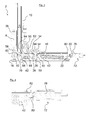
- Fig. 4 shows a detailed view of the arranged on the hinge bearing 18 damper 72.
- a plunger 76 is arranged, which is actuated by an angle 80 of a pusher member 82.
- the plunger 76 represents a commercially available, in particular from the furniture industry known damping element.
- a movement of a pivot lever 84 is transmitted via the pusher 82 to the plunger 76 of the damper 72.
- the guide member 26 of the pivot lever 84 is rotatably on the clamping lever 38 ( Fig. 3 ) stored. If the tensioning lever 38 moves in the direction of the damper 72 by closing the door, a blocking nose 88 causes a rotation of the pivoting lever 84, as a result of which the pushrod 76 is moved.
- the pivot lever 84 which corresponds at one end to the locking lug 88 and at the other end to the thrust element 82, a relative to the movement of the clamping lever 38 longer thrust movement of the thrust element 82 is achieved via the lever action.
- the locking nose 88 is formed by a issued from the hinge housing 12 sheet metal tabs. The position of the locking lug 88 is selected such that the plunger 76 moves from a door opening angle ⁇ of 30 ° and the door 2 is thereby damped.
- Fig. 6 shows an embodiment of the hinge housing 12, in which two keyhole-shaped openings 90 are formed, through which the thrust element 82 is mounted without tools with disassembled damper 72.
- the thrust element 82 has two angle-shaped holding elements 91, which correspond to the openings 90.
- this is Push element 82 can be inserted via contours arranged on the side walls 14 of the hinge housing 12 in accordance with a drawer guide.
Abstract
Description
- Die vorliegende Erfindung betrifft ein Haushaltsgerät, insbesondere einen Garofen gemäß dem Oberbegriff des Patentanspruchs 1.
- Aus der Druckschrift
DE103 60 386 ist ein gattungsgemäßer Garofen bekannt, bei dem eine Tür zum Verschließen der Beschickungsöffnung wenigstens zwei Trägerelemente umfasst, die jeweils über einen Verbindungsflansch mit der Außenscheibe verbunden sind. Senkrecht zur Außenscheibe nach innen erstrecken sich vom Verbindungsflansch weg Scheibenhalteteile, die an den einander zugewandten Innenseiten jeweils Aufnahmenuten für weitere Türscheiben aufweisen. Die Aufnahmenuten sind an einer Seite, in der Regel der Unterseite mit einem Abstützteil abgeschlossen. An den von den einander zugewandten Innenseiten mit den Aufnahmenuten der Scheibenhalteteile abgewandten Außenseiten ist jeweils ein Aufnahmekanal angeformt. Auf der gleichen Höhe wie die Abstützteile münden die Aufnahmekanäle in jeweils einer rechteckigen Aufnahmeöffnung, die zur Aufnahme eines zweiten Scharnierteils jeweils eines Türscharniers vorgesehen ist. - Der Erfindung liegt die Aufgabe zugrunde, eine gegenüber dem Stand der Technik verbesserte Scharniervorrichtung für ein Haushaltsgerät zu schaffen.
- Diese Aufgabe wird durch ein Haushaltsgerät mit den Merkmalen des Patentanspruchs 1 gelöst. Vorteilhafte Ausgestaltungen sind den Unteransprüchen einzeln oder in Kombination zu entnehmen.
- Gemäß dem kennzeichnenden Teil des Patentanspruches 1 ist das Scharniergehäuse in einer, über die Scharniervorrichtung relativ zur ersten Komponente beweglich angeordneten, zweiten Komponente des Haushaltsgerätes werkzeuglos montierbar und/oder demontierbar. Dabei ist insbesondere unter der ersten Komponente die Tür und unter der zweiten Komponente das Haushaltsgerät ohne Tür oder umgekehrt zu verstehen. Durch eine derartige, werkzeuglose Demontierbarkeit ist beispielsweise eine Grundlage zur einfachen Nachrüstung eines Dämpfers geschaffen.
- Bei einer bevorzugten Ausgestaltung ist das Scharniergehäuse in ein Scharnierelager einschiebbar. Durch Einschieben bzw. Herausziehen ist das Scharniergehäuse in einfacher, sinnfälliger Weise montierbar, bzw. demontierbar.
- Vorzugsweise hält ein elastisches Element das Scharniergehäuse in einer Arbeitsposition innerhalb des Scharnierlagers. Dies ermöglicht eine Fixierung des eingeschobenen Scharniergehäuses innerhalb des Scharnierlagers ebenso wie eine werkzeuglose Entnahme des Scharniergehäuses durch Überwinden einer durch das elastische Element auf das Scharniergehäuse aufgebrachten Kraft.
- Das elastische Element ist derart angeordnet, dass es das Scharniergehäuse mit einer definierten Kraft nach unten drückt. Bei einer vorteilhaften Weiterbildung der Scharniervorrichtung wird beim Öffnen der Tür das Scharniergehäuse gegenüber dem Scharnierlager angehoben. Dadurch wird beim Öffnen der Tür diese selbst angehoben und somit die Realisierung enger Spaltmaße zwischen der Tür und angrenzenden Möbeln ermöglicht. Bei einer derartigen Ausbildung hat das elastische Element zusätzlich zur Rastfunktion eine Rückstellfunktion für das angehobene Scharniergehäuse.
- Indem das elastische Element im Wesentlichen als Blattfeder ausgebildet ist, ist es kostengünstig herstellbar und zudem leicht an vorhandene Geometrien anpassbar. So kann die Blattfeder an ihrem Ende noch eine taschenartige Biegung aufweisen, über die sie durch Aufstecken am Scharnierlager befestigbar ist.
- Bevorzugt ist es, wenn das Scharnierlager und das Scharniergehäuse miteinander korrespondierende Befestigungselemente aufweisen, durch die beim Montieren des Scharniergehäuses dieses mit dem Scharnierlager über das elastische Element lösbar in einer Arbeitsposition verrastet.
- In einer vorteilhaften Ausgestaltung der Erfindung sind die korrespondierenden Befestigungselemente als ein im Scharniergehäuse angeordnetes Führungselement und eine im Scharnierlager angeordnete Kulisse ausgebildet. Dadurch wird das Scharniergehäuse beim Einschieben in das Scharnierlager beispielsweise angehoben, wodurch das elastische Element vorgespannt wird. Durch weiteres Einschieben wird über die Bewegung des Führungselementes in der Kulisse das Scharniergehäuse wieder abgesenkt. Das elastische Element entspannt sich und das Scharniergehäuse wird in einer durch die Kulissenform vorgegeben Arbeitsposition gehalten.
- Zur Vereinfachung ist das Führungselement im Scharniergehäuse als eine Lagerstelle eines in Richtung einer Gewichtsausgleichsfeder beweglichen Spannhebels ausgebildet. So kann das Führungselement als verlängerte Achse ausgebildet sein, die eine Bewegung des Spannhebels führt. Da eine Führung des Spannhebels üblicherweise ohnehin notwendig ist, ergibt sich die Einsparung eines extra Teiles.
- In einer weiteren Ausgestaltung wird vorgeschlagen, dass die Kulisse derart ausgebildet ist, dass sie sich in Längsrichtung des Scharnierlagers erstreckt und dabei ein Plateau aufweist, das gegenüber zumindest einem der Endbereiche erhöht angeordnet ist. Aufgrund des erhöht angeordneten Plateaus und den dadurch tiefer liegenden Endbereichen der Kulisse ergibt sich eine Rastfunktion des Scharniergehäuses innerhalb des Scharnierlagers in einer Arbeitsposition. Darüber hinaus sind durch die Ausbildung des Plateaus in seiner Höhe und Länge bezüglich der Kulisse die Einschubkräfte bzw. die Entnahmekräfte des Scharniergehäuses aus dem Scharnierlager festlegbar.
- Um eine durch das Führungselement verursachte Schwenkbewegung des Scharniergehäuses beim Einschieben in das Scharnierlager zu ermöglichen, ist die lichte Weite einer Einschuböffnung entsprechend vergrößert. Insbesondere ist die lichte Weite entgegen der Richtung einer vom elastischen Element auf das Scharniergehäuse wirkenden Kraft vergrößert. Drückt das elastische Element beispielsweise das Scharniergehäuse nach unten, so ist die lichte Weite der Einschuböffnung nach oben hin erweitert. Zudem weist die Einschuböffnung parallel zu einer Längserstreckung des Führungselementes eine Verbreiterung auf, die ein Einführen des Führungselementes in die Kulisse ermöglicht.
- Vorzugsweise weisen das Scharniergehäuse und das Scharnierlager jeweils an ihren der Tür abgewandten Endabschnitten miteinander korrespondierende Elemente auf, die in einer Arbeitsposition des Scharniergehäuses formschlüssig miteinander im Eingriff sind. Das Element am Scharnierlager kann beispielsweise als ein von der Seitenwand ausgestellter Lappen ausgebildet sein, der in eine entsprechende Ausklinkung des Scharniergehäuses eingreift. Alternativ ist die Halterung einer Gewichtsausgleichsfeder als verlängerte Lagerachse ausgebildet, die in korrespondierende Durchbrüche am Scharnierlager eingreift, wobei der Eingriff kurz vor Erreichen der Arbeitsstellung des Scharniergehäuses erfolgt.
- Weitere Merkmale und Vorteile der Erfindung ergeben sich aus der nachfolgenden Beschreibung eines Ausführungsbeispiels unter Bezugnahme auf die beigefügten Figuren. Es zeigen:
- Fig. 1
- ein Haushaltsgerät in einer räumlichen Darstellung;
- Fig. 2
- eine Scharniervorrichtung des Haushaltsgerätes mit einem in einem Scharnierlager montierten Scharniergehäuse;
- Fig. 3
- eine Schnittdarstellung entlang der Linie III - III durch die in
Fig. 2 gezeigte Scharniervorrichtung in einer Einbaulage im Haushaltsgerät; - Fig. 4
- eine Detaildarstellung aus
Fig. 3 ; - FIG. 5
- eine Detaildarstellung eines Schubelementes der Scharniervorrichtung und der an das Schubelement angreifenden Elemente in einer Schnittdarstellung und
- Fig. 6
- eine räumliche Darstellung des Scharniergehäuses.
- In
Fig. 1 ist ein Haushaltsgerät mit einer über eine Scharniervorrichtung schwenkbar gelagerten Tür 2 gezeigt, in der beidseitig jeweils ein Schwert 6 der Scharniervorrichtung gelagert ist. Das Haushaltsgerät ist nach außen durch einen Korpus 8 begrenzt, der zwei Seitenwände, einen Boden, eine Decke, eine Rückwand und einen Flansch 10 aufweist. Die Schwerter 6 tauchen jeweils durch eine Aufnahmeöffnung 4 im Flansch 10 durch und sind in der Tür 2 lösbar gehalten. - Innerhalb des Korpus 8, im Wesentlichen hinter dem Flansch 10, sind zwei identisch ausgebildete Scharniergehäuse 12 (
Fig. 2 ) angeordnet. Die Scharniergehäuse 12 sind in Ihrer Längsrichtung 1 im Wesentlichen waagrecht im Korpus 8 angeordnet. Das Scharniergehäuse 12 weist Seitenwände 14 auf, in denen türseitig eine Scharnierachse 16 befestigt ist. Das Schwert 6 ist durch die Scharnierachse 16 drehbar gegenüber dem Scharniergehäuse 12 gelagert. Das Scharniergehäuse 12 ist innerhalb des Korpus 8 in einem Scharnierlager 18 befestigt. In Richtung der Tür 2 weist das Scharnierlager 18 eine Einschuböffnung 20 für das Scharniergehäuse 12 auf. Die Einschuböffnung 20 weist gegenüber dem angrenzenden Bereich des Scharnierlagers 18 eine größere Breite b auf. Das Scharniergehäuse 12 ist türseitig über die Einschuböffnung 20 in das Scharnierlager 18 einschiebbar und verrastet in einer Endposition mit dem Scharnierlager 18. In einem der Einschuböffnung 20 gegenüberliegenden, hinteren Abschnitt des Scharnierlagers 18 sind gegenüberliegend an den beiden Seitenflächen ausgebildete Durchbrüche 21 angeordnet. Diese sind nahe einer Unterseite 24 des Scharnierlagers 18 angeordnet und bilden eine Aufnahme für die Lagerachse 22. Ist die Lagerachse 22 mit den Durchbrüchen 21 in Eingriff, dann ist dadurch das Scharniergehäuse 12 im Scharnierlager 18 schwenkbar gelagert. Ein Führungselement 26 ist als eine, parallel zur Scharnierachse 16 verlaufende Achse ausgebildet, die in zwei gegenüberliegend angeordneten Schlitzen 28 der Seitenwände 14 des Scharniergehäuses 12 verschiebbar gelagert ist. Das Führungselement 26 ragt über die Seitenwände 14 des Scharniergehäuses 12 hinaus und stützt sich dadurch in einer Kulisse 30 des Scharnierlagers 18 ab. Die Kulisse 30 weist mittig ein Plateau 32 auf, das den größten Abstand der Kulisse 30 zur Unterseite 24 des Scharnierlagers 18 bildet. Ein elastisches Element 34, das oberhalb der Einschuböffnung 20 am Scharnierlager 18 angeordnet ist, wirkt auf das Scharniergehäuse 12 und drückt dieses mit einer Kraft F in Richtung der Unterseite 24. Das elastische Element 34 ist in Form einer doppelzüngigen Blattfeder ausgebildet. Das Scharniergehäuse 12 ist bei geschlossener Tür 2 über die Lagerachse 22 und über das elastische Element 34 in seiner Endposition gehalten. Das Scharniergehäuse 12 ist entgegen der Federkraft des elastischen Elements 34 aus dem Scharnierlager 18 türseitig herausziehbar. Dabei gleitet das Führungselement 26 von seiner Endlage über das Plateau 32 und deformiert dabei das elastische Element 34. Nach dem Plateau 32 führt die Kulisse 30 das Führungselement 26, unterstützt durch das elastische Element 34, wieder in Richtung Unterseite 24. In diesem Abschnitt der Kulisse 30 ist die Breite b des Scharnierlagers größer, wodurch das Führungselement 26 aus der Kulisse 30 gleitet, und das Scharniergehäuse 12 dadurch in Richtung der Tür 2 entnehmbar ist. An einem der Tür 2 gegenüberliegenden Endbereich des Scharnierlagers 18 ist ein Dämpfer 72 über ein Rastelement 74 befestigt. Das Rastelement 74 greift in eine Aussparung 78 des Scharnierlagers 18 ein. Rastelement 74 und Aussparung 78 sind derart ausgebildet, dass der Dämpfer 72 werkzeuglos montierbar ist. - In
Fig. 3 ist eine Aufnahme 36 der Tür 2 dargestellt, in der das Schwert 6 gelagert ist. Ein Spannhebel 38 ist über ein von der Scharnierachse 16 beabstandetes Spannhebellager 40 an das Schwert 6 gekoppelt. Bei einer Schwenkbewegung der Tür 2 läuft das bei geschlossener Tür 2 rechts von der Scharnierachse 16 angeordnete Spannhebellager 40 in einer Kreisbewegung um die Scharnierachse 16. Der Spannhebel 38 ist mit einer Gewichtsausgleichsfeder 42 gekoppelt. Diese bildet eine Gegenkraft zum Gewicht der Tür 2, wodurch ein komfortables Öffnen und Schließen der Tür 2 gewährleistet ist. Die Gewichtsausgleichsfeder 42 ist über eine als Loch ausgebildete Federaufnahme 46 in einem Verstellhebel 48 gehalten. Der Verstellhebel 48 ist über ein Verstellhebellager 50 drehbar am Spannhebel 38 gelagert. Ein Ende des Verstellhebels 48 ragt aus dem Scharniergehäuse 12 nach oben heraus und taucht zwischen den beiden Zungen des elastischen Elements 34 durch. An diesem Ende ist ein Justierelement 52 über ein Spannelement 54 gelagert. Das Spannelement 54 ist im Wesentlichen als eine Mutter ausgebildet, in die ein am Justierelement 52 ausgeprägtes Gewinde (nicht gezeigt) eingreift. Das Spannelement 54 ist drehbar am Verstellhebel 48 gelagert, um eine Schwenkbewegung des Justierelementes 52 zu ermöglichen. Das als Schraube ausgebildete Justierelement 52 dient zum Einstellen einer Federvorspannung der Gewichtsausgleichsfeder 42. Über ein Loslager 56 ist das Justierelement 52 mit seinem türseitigen Ende an den Spannhebel 38 derart angebunden, dass das Justierelement 52 drehbar gelagert ist. Beim Öffnen der Tür 2 läuft das Spannhebellager 40 in einer Kreisbewegung um die Scharnierachse 16, wobei zunächst der Spannhebel 38 im Wesentlichen angehoben wird. Durch das Anheben des Spannhebels 38 wird über das Loslager 56 auch das als Schraube ausgebildete Justierelement 52 türseitig angehoben. Der türseitig angeordnete Schraubenantrieb (Schlitz) des Justierelements 52 ist durch das Anheben frei zugänglich für einen Schraubendreher, wodurch eine Federvorspannung der Gewichtsausgleichsfeder 42 einstellbar ist. Ein Riegel 58 ist beweglich am Schwert 6 gelagert und bildet eine Lagerstelle für einen beweglichen Hebel 60. Riegel 58 und Hebel 60 sind derart ausklappbar, dass sich der Hebel 60 beim Schließen der Tür 2 an einer Rolle 62 abstützt und dadurch ein weiteres Schließen der Tür 2 verhindert. Eine zuziehende Kraft der Gewichtsausgleichsfeder 42 auf die Tür 2 wird dadurch abgefangen. Die Tür 2 kann in diesem Zustand für Reinigungszwecke werkzeuglos entnommen werden, indem die Schwerter 6 aus ihren Aufnahmen 36 gezogen werden. Durch Einschieben der Schwerter 6 in die Aufnahmen 36 ist die Tür 2 wieder montierbar. Wird die Tür 2 etwas weiter geöffnet, werden der Hebel 60 und der Riegel 58 frei und sind einklappbar. Die Tür 2 ist jetzt wieder vollständig schließbar. Die Rolle 62 ist an einem Bügel 64 befestigt, der über den Drehpunkt 66 drehbar am Spannhebel 38 gelagert ist. Der Bügel 64 bildet eine Lagerstelle für eine Druckfeder 68, die mit ihrem gegenüberliegenden Ende am Spannhebel 38 gehalten ist. Das Schwert 6 weist nahe der Scharnierachse 16 eine Anlagekontur 70 auf, die derart ausgebildet ist, dass sie bei einem Öffnungswinkel α von ca. 25° die Schließbewegung der Tür 2 durch Anlage an der Rolle 62 stoppt. Zum weiteren Schließen der Tür 2 wird diese entgegen der Federkraft der Druckfeder 68 weiter zugedrückt. Die Anlagekontur 70 ist derart ausgebildet, dass nahe der Schließstellung der Tür 2 über die Druckfeder 68 eine zusätzliche Kraft in Richtung Schließstellung auf die Tür 2 ausübt wird. -
Fig. 4 zeigt eine Detaildarstellung des am Scharnierlager 18 angeordneten Dämpfers 72. Im Dämpfer 72 ist ein Stößel 76 angeordnet, der über einen Winkel 80 eines Schubelements 82 betätigt wird. Der Stößel 76 stellt ein handelsübliches, insbesondere aus der Möbelbranche bekanntes Dämpfungselement dar. - Gemäß
Fig. 5 wird eine Bewegung eines Schwenkhebels 84 über das Schubelement 82 auf den Stößel 76 des Dämpfers 72 übertragen. Durch das Führungselement 26 ist der Schwenkhebel 84 drehbar am Spannhebel 38 (Fig. 3 ) gelagert. Bewegt sich der Spannhebel 38 durch Schließen der Tür in Richtung Dämpfer 72, so bewirkt eine Sperrnase 88 eine Drehung des Schwenkhebels 84, wodurch der Stößel 76 bewegt wird. Durch den Schwenkhebel 84, der an einem Ende mit der Sperrnase 88 und am anderen Ende mit dem Schubelement 82 korrespondiert, wird über die Hebelwirkung eine gegenüber der Bewegung des Spannhebels 38 längere Schubbewegung des Schubelementes 82 erreicht. Dieses ist notwendig, da die Bewegungskomponente des Spannhebels 38 in Richtung Dämpfer 72 bei kleinem Öffnungswinkel α der Tür 2 für eine ausreichende Dämpfung zu gering ist. Die Sperrnase 88 ist durch einen aus dem Scharniergehäuse 12 ausgestellten Blechlappen gebildet. Die Position der Sperrnase 88 ist derart gewählt, dass sich der Stößel 76 ab einem Türöffnungswinkel α von 30° bewegt und die Tür 2 dadurch gedämpft wird. -
Fig. 6 zeigt eine Ausführungsform des Scharniergehäuses 12, in der zwei schlüssellochförmige Öffnungen 90 ausgebildet sind, durch die das Schubelement 82 bei demontiertem Dämpfer 72 werkzeuglos montierbar ist. Das Schubelement 82 weist zwei winkelförmig ausgebildete Halteelemente 91 auf, die mit den Öffnungen 90 korrespondieren. In einer alternativen Ausführungsform (nicht gezeigt) ist das Schubelement 82 über an den Seitenwänden 14 des Scharniergehäuses 12 angeordneten Konturen entsprechend einer Schubladenführung einschiebbar. -
- 2
- Tür
- 4
- Aufnahmeöffnung
- 6
- Schwert
- 8
- Korpus
- 10
- Flansch
- 12
- Scharniergehäuse
- 14
- Seitenwand
- 16
- Scharnierachse
- 18
- Scharnierlager
- 20
- Einschuböffnung
- 21
- Durchbruch
- 22
- Lagerachse
- 24
- Unterseite
- 26
- Führungselement
- 28
- Schlitz
- 30
- Kulisse
- 32
- Plateau
- 34
- elastisches Element
- 36
- Aufnahme
- 38
- Spannhebel
- 40
- Spannhebellager
- 42
- Gewichtsausgleichsfeder
- 46
- Federaufnahme
- 48
- Verstellhebel
- 50
- Verstellhebellager
- 52
- Justierelement
- 54
- Spannelement
- 56
- Loslager
- 58
- Riegel
- 60
- Hebel
- 62
- Rolle
- 64
- Bügel
- 66
- Drehpunkt
- 68
- Druckfeder
- 70
- Anlagekontur
- 72
- Dämpfer
- 74
- Rastelement
- 76
- Stößel
- 78
- Aussparung
- 80
- Winkel
- 82
- Schubelement
- 84
- Schwenkhebel
- 88
- Sperrnase
- 90
- Öffnung
- 91
- Halteelement
- α
- Öffnungswinkel
- b
- Breite
- F
- Kraft
- I
- Längsrichtung
Claims (11)
- Haushaltsgerät, insbesondere Garofen mit einer Scharniervorrichtung für eine Tür (2), mit einem Scharniergehäuse (12) und einem daran drehbar gelagerten Schwert (6), das in einer ersten Komponente des Haushaltsgerätes angeordnet ist, dadurch gekennzeichnet, dass das Scharniergehäuse (12) in einer, über die Scharniervorrichtung relativ zur ersten Komponente beweglich angeordneten, zweiten Komponente des Haushaltsgerätes werkzeuglos montierbar und/oder demontierbar ist.
- Haushaltsgerät nach Anspruch 1 dadurch gekennzeichnet, dass das Scharniergehäuse (12) in ein Scharnierlager (18) einschiebbar ist.
- Haushaltsgerät nach Anspruch 2 dadurch gekennzeichnet, dass ein elastisches Element (34) das Scharniergehäuse (12) in einer Arbeitsposition innerhalb des Scharnierlagers (18) hält.
- Haushaltsgerät nach Anspruch 3, dadurch gekennzeichnet, dass das elastische Element (34) derart angeordnet ist, dass es das Scharniergehäuse (12) mit einer Kraft (F) nach unten drückt.
- Haushaltsgerät nach Anspruch 3 oder 4, dadurch gekennzeichnet, dass das elastische Element (34) im Wesentlichen als Blattfeder ausgebildet ist.
- Haushaltsgerät nach einem der vorhergehenden Ansprüche 3 bis 5, dadurch gekennzeichnet, dass das Scharnierlager (18) und das Scharniergehäuse (12) miteinander korrespondierende Befestigungselemente aufweisen, die beim Montieren des Scharniergehäuses (12) dieses mit dem Scharnierlager (18) über das elastische Element (34) lösbar in einer Arbeitsposition verrasten.
- Haushaltsgerät nach Anspruch 6, dadurch gekennzeichnet, dass die korrespondierenden Befestigungselemente als ein im Scharniergehäuse (12) angeordnetes Führungselement (26) und eine im Scharnierlager (18) angeordnete Kulisse (30) ausgebildet sind.
- Haushaltsgerät nach Anspruch 7, dadurch gekennzeichnet, dass das Führungselement (26) im Scharniergehäuse (12) als eine Lagerstelle eines in Richtung einer Gewichtsausgleichsfeder (42) beweglichen Spannhebels (38) ausgebildet ist.
- Haushaltsgerät nach Anspruch 7 oder 8, dadurch gekennzeichnet, dass die Kulisse (30) derart ausgebildet ist, dass sie sich in Längsrichtung (I) des Scharnierlagers (18) erstreckt und dabei ein Plateau (32) aufweist, das gegenüber zumindest einem der Endbereiche erhöht angeordnet ist.
- Haushaltsgerät nach einem der vorhergehenden Ansprüche 7 bis 9, dadurch gekennzeichnet, dass die lichte Weite einer Einschuböffnung (20) derart vergrößert ist, dass eine durch das Führungselement (26) verursachte Schwenkbewegung des Scharniergehäuses (12) beim Einschieben in das Scharnierlager (18) ermöglicht ist.
- Haushaltsgerät nach einem der vorhergehenden Ansprüche 2 bis 10, dadurch gekennzeichnet, dass das Scharniergehäuse (12) und das Scharnierlager (18) jeweils an ihren der Tür (2) abgewandten Endabschnitten miteinander korrespondierende Elemente aufweisen, die in einer Arbeitsposition des Scharniergehäuses (12) formschlüssig miteinander im Eingriff sind.
Applications Claiming Priority (1)
| Application Number | Priority Date | Filing Date | Title |
|---|---|---|---|
| DE102010002100A DE102010002100A1 (de) | 2010-02-18 | 2010-02-18 | Haushaltsgerät, insbesondere Garofen |
Publications (3)
| Publication Number | Publication Date |
|---|---|
| EP2362049A2 true EP2362049A2 (de) | 2011-08-31 |
| EP2362049A3 EP2362049A3 (de) | 2014-06-25 |
| EP2362049B1 EP2362049B1 (de) | 2015-12-16 |
Family
ID=44009876
Family Applications (1)
| Application Number | Title | Priority Date | Filing Date |
|---|---|---|---|
| EP11152919.4A Active EP2362049B1 (de) | 2010-02-18 | 2011-02-01 | Haushaltsgerät, insbesondere Garofen |
Country Status (2)
| Country | Link |
|---|---|
| EP (1) | EP2362049B1 (de) |
| DE (1) | DE102010002100A1 (de) |
Families Citing this family (2)
| Publication number | Priority date | Publication date | Assignee | Title |
|---|---|---|---|---|
| DE102012214423B4 (de) * | 2012-08-14 | 2024-03-14 | BSH Hausgeräte GmbH | Geschirrspülmaschine mit einem über eine Gelenkanordnung schwenkbaren Türelement |
| DE102012214424B4 (de) * | 2012-08-14 | 2017-02-02 | BSH Hausgeräte GmbH | Geschirrspülmaschine mit wenigstens einer beidseitig gelagerten Schwenkachse für ihr Türelement |
Citations (1)
| Publication number | Priority date | Publication date | Assignee | Title |
|---|---|---|---|---|
| DE10360386A1 (de) | 2003-12-22 | 2005-07-14 | Electrolux Home Products Corporation N.V. | Tür zum Verschließen der Beschickungsöffnung eines Garraums eines Garofens, insbesondere eines Haushaltsgarofens |
Family Cites Families (4)
| Publication number | Priority date | Publication date | Assignee | Title |
|---|---|---|---|---|
| US2873737A (en) * | 1956-12-20 | 1959-02-17 | Gen Electric | Removable oven door structure |
| US3327701A (en) * | 1966-06-13 | 1967-06-27 | Moffats Ltd | Hinge mechanism |
| US3842542A (en) * | 1973-06-01 | 1974-10-22 | Gen Electric | Removable oven door hinge system |
| DE102007041909A1 (de) * | 2007-09-04 | 2009-03-05 | BSH Bosch und Siemens Hausgeräte GmbH | Scharniergehäuse für eine Hausgerätetür |
-
2010
- 2010-02-18 DE DE102010002100A patent/DE102010002100A1/de not_active Withdrawn
-
2011
- 2011-02-01 EP EP11152919.4A patent/EP2362049B1/de active Active
Patent Citations (1)
| Publication number | Priority date | Publication date | Assignee | Title |
|---|---|---|---|---|
| DE10360386A1 (de) | 2003-12-22 | 2005-07-14 | Electrolux Home Products Corporation N.V. | Tür zum Verschließen der Beschickungsöffnung eines Garraums eines Garofens, insbesondere eines Haushaltsgarofens |
Also Published As
| Publication number | Publication date |
|---|---|
| EP2362049A3 (de) | 2014-06-25 |
| DE102010002100A1 (de) | 2011-08-18 |
| EP2362049B1 (de) | 2015-12-16 |
Similar Documents
| Publication | Publication Date | Title |
|---|---|---|
| EP2362050A2 (de) | Scharniervorrichtung, Haushaltsgerät mit einer Tür und Verfahren zum Nachrüsten eines Dämpfers | |
| EP1743128B1 (de) | Haushaltsgerät mit verschwenkbarem anzeigeschirm | |
| EP2362044B1 (de) | Haushaltsgerät, insbesondere Garofen, sowie Verfahren zum Verschieben einer Tür | |
| EP2250929B1 (de) | Schrankteil mit herausziehbarem Ausziehteil | |
| DE60301799T2 (de) | Vorrichtung zum Anordnen und Auslieferung von Komponenten | |
| DE102012016938A1 (de) | Scharnier für ein Gerät | |
| EP2209411B1 (de) | Haushaltsgerät mit türgewichtsausgleichsvorrichtung | |
| DE202012002502U1 (de) | Vorrichtung zur Unterstützung und Erleichterung des Kipp-Öffnens und -Schließens für ein Fenster oder eine Tür | |
| EP2992156B1 (de) | Führungsanordnung einer schiebetür, schiebetür und möbel | |
| EP3658824B1 (de) | Gargerät mit versenkbarer tür, die eine spezifische haltefeder für eine lagerbuchse aufweist | |
| AT520766B1 (de) | Schubladenausziehführung | |
| EP2362049B1 (de) | Haushaltsgerät, insbesondere Garofen | |
| EP3838068A1 (de) | Schubladenausziehführung | |
| EP3758553B1 (de) | Möbel oder haushaltsgerät und verfahren zur montage einer funktionseinheit eines schubelements in einem möbel oder haushaltsgerät | |
| EP2168455B1 (de) | Führungsschiene einer Möbelauszugsführung | |
| DE102011109552B4 (de) | Beschlagsystem zum Führen einer Verschlussklappe eines Möbelstücks sowie ein Möbelstück mit diesem | |
| EP3086065B1 (de) | Haushaltskältegerät mit einem lagerwinkel mit plattenförmigem auflagedach | |
| DE102010016594A1 (de) | Auszugsführung für Möbel oder Haushaltsgeräte | |
| EP2362048B1 (de) | Haushaltsgerät, insbesondere Garofen | |
| DE60301773T9 (de) | Verfahren und Gerät für die Montage eines Haushaltgeräts in einem Schrank | |
| DE102011081582A1 (de) | Schienenauszugsvorrichtung für ein Hausgerät sowie Hausgerät mit einer Schienenauszugsvorrichtung | |
| EP2307646A1 (de) | Dämpfungseinrichtung für möbeltüren | |
| DE102021124934A1 (de) | Möbelkomponente und Verfahren | |
| DE102008061550A1 (de) | Dämpfungseinrichtung für Möbeltüren | |
| EP3091317B1 (de) | Haushaltskältegerät mit einer lagereinheit für eine tür, die ein federelement aufweist sowie verfahren zum bewegen einer tür |
Legal Events
| Date | Code | Title | Description |
|---|---|---|---|
| PUAI | Public reference made under article 153(3) epc to a published international application that has entered the european phase |
Free format text: ORIGINAL CODE: 0009012 |
|
| AK | Designated contracting states |
Kind code of ref document: A2 Designated state(s): AL AT BE BG CH CY CZ DE DK EE ES FI FR GB GR HR HU IE IS IT LI LT LU LV MC MK MT NL NO PL PT RO RS SE SI SK SM TR |
|
| AX | Request for extension of the european patent |
Extension state: BA ME |
|
| PUAL | Search report despatched |
Free format text: ORIGINAL CODE: 0009013 |
|
| AK | Designated contracting states |
Kind code of ref document: A3 Designated state(s): AL AT BE BG CH CY CZ DE DK EE ES FI FR GB GR HR HU IE IS IT LI LT LU LV MC MK MT NL NO PL PT RO RS SE SI SK SM TR |
|
| AX | Request for extension of the european patent |
Extension state: BA ME |
|
| RIC1 | Information provided on ipc code assigned before grant |
Ipc: E05D 7/12 20060101ALI20140516BHEP Ipc: F24C 15/02 20060101ALI20140516BHEP Ipc: E05F 1/12 20060101AFI20140516BHEP |
|
| 17P | Request for examination filed |
Effective date: 20150105 |
|
| RBV | Designated contracting states (corrected) |
Designated state(s): AL AT BE BG CH CY CZ DE DK EE ES FI FR GB GR HR HU IE IS IT LI LT LU LV MC MK MT NL NO PL PT RO RS SE SI SK SM TR |
|
| RAP1 | Party data changed (applicant data changed or rights of an application transferred) |
Owner name: BSH HAUSGERAETE GMBH |
|
| RIC1 | Information provided on ipc code assigned before grant |
Ipc: E05D 7/12 20060101ALI20150601BHEP Ipc: E05F 1/12 20060101AFI20150601BHEP Ipc: F24C 15/02 20060101ALI20150601BHEP |
|
| GRAP | Despatch of communication of intention to grant a patent |
Free format text: ORIGINAL CODE: EPIDOSNIGR1 |
|
| INTG | Intention to grant announced |
Effective date: 20150710 |
|
| GRAS | Grant fee paid |
Free format text: ORIGINAL CODE: EPIDOSNIGR3 |
|
| GRAA | (expected) grant |
Free format text: ORIGINAL CODE: 0009210 |
|
| AK | Designated contracting states |
Kind code of ref document: B1 Designated state(s): AL AT BE BG CH CY CZ DE DK EE ES FI FR GB GR HR HU IE IS IT LI LT LU LV MC MK MT NL NO PL PT RO RS SE SI SK SM TR |
|
| REG | Reference to a national code |
Ref country code: GB Ref legal event code: FG4D Free format text: NOT ENGLISH |
|
| REG | Reference to a national code |
Ref country code: CH Ref legal event code: EP |
|
| REG | Reference to a national code |
Ref country code: IE Ref legal event code: FG4D Free format text: LANGUAGE OF EP DOCUMENT: GERMAN |
|
| REG | Reference to a national code |
Ref country code: AT Ref legal event code: REF Ref document number: 765647 Country of ref document: AT Kind code of ref document: T Effective date: 20160115 |
|
| REG | Reference to a national code |
Ref country code: DE Ref legal event code: R096 Ref document number: 502011008495 Country of ref document: DE |
|
| REG | Reference to a national code |
Ref country code: NL Ref legal event code: MP Effective date: 20151216 |
|
| REG | Reference to a national code |
Ref country code: LT Ref legal event code: MG4D |
|
| PG25 | Lapsed in a contracting state [announced via postgrant information from national office to epo] |
Ref country code: LT Free format text: LAPSE BECAUSE OF FAILURE TO SUBMIT A TRANSLATION OF THE DESCRIPTION OR TO PAY THE FEE WITHIN THE PRESCRIBED TIME-LIMIT Effective date: 20151216 Ref country code: HR Free format text: LAPSE BECAUSE OF FAILURE TO SUBMIT A TRANSLATION OF THE DESCRIPTION OR TO PAY THE FEE WITHIN THE PRESCRIBED TIME-LIMIT Effective date: 20151216 Ref country code: NO Free format text: LAPSE BECAUSE OF FAILURE TO SUBMIT A TRANSLATION OF THE DESCRIPTION OR TO PAY THE FEE WITHIN THE PRESCRIBED TIME-LIMIT Effective date: 20160316 |
|
| PG25 | Lapsed in a contracting state [announced via postgrant information from national office to epo] |
Ref country code: RS Free format text: LAPSE BECAUSE OF FAILURE TO SUBMIT A TRANSLATION OF THE DESCRIPTION OR TO PAY THE FEE WITHIN THE PRESCRIBED TIME-LIMIT Effective date: 20151216 Ref country code: LV Free format text: LAPSE BECAUSE OF FAILURE TO SUBMIT A TRANSLATION OF THE DESCRIPTION OR TO PAY THE FEE WITHIN THE PRESCRIBED TIME-LIMIT Effective date: 20151216 Ref country code: NL Free format text: LAPSE BECAUSE OF FAILURE TO SUBMIT A TRANSLATION OF THE DESCRIPTION OR TO PAY THE FEE WITHIN THE PRESCRIBED TIME-LIMIT Effective date: 20151216 Ref country code: FI Free format text: LAPSE BECAUSE OF FAILURE TO SUBMIT A TRANSLATION OF THE DESCRIPTION OR TO PAY THE FEE WITHIN THE PRESCRIBED TIME-LIMIT Effective date: 20151216 Ref country code: SE Free format text: LAPSE BECAUSE OF FAILURE TO SUBMIT A TRANSLATION OF THE DESCRIPTION OR TO PAY THE FEE WITHIN THE PRESCRIBED TIME-LIMIT Effective date: 20151216 Ref country code: BE Free format text: LAPSE BECAUSE OF NON-PAYMENT OF DUE FEES Effective date: 20160229 Ref country code: GR Free format text: LAPSE BECAUSE OF FAILURE TO SUBMIT A TRANSLATION OF THE DESCRIPTION OR TO PAY THE FEE WITHIN THE PRESCRIBED TIME-LIMIT Effective date: 20160317 |
|
| PG25 | Lapsed in a contracting state [announced via postgrant information from national office to epo] |
Ref country code: IT Free format text: LAPSE BECAUSE OF FAILURE TO SUBMIT A TRANSLATION OF THE DESCRIPTION OR TO PAY THE FEE WITHIN THE PRESCRIBED TIME-LIMIT Effective date: 20151216 Ref country code: ES Free format text: LAPSE BECAUSE OF FAILURE TO SUBMIT A TRANSLATION OF THE DESCRIPTION OR TO PAY THE FEE WITHIN THE PRESCRIBED TIME-LIMIT Effective date: 20151216 Ref country code: CZ Free format text: LAPSE BECAUSE OF FAILURE TO SUBMIT A TRANSLATION OF THE DESCRIPTION OR TO PAY THE FEE WITHIN THE PRESCRIBED TIME-LIMIT Effective date: 20151216 |
|
| PG25 | Lapsed in a contracting state [announced via postgrant information from national office to epo] |
Ref country code: SM Free format text: LAPSE BECAUSE OF FAILURE TO SUBMIT A TRANSLATION OF THE DESCRIPTION OR TO PAY THE FEE WITHIN THE PRESCRIBED TIME-LIMIT Effective date: 20151216 Ref country code: IS Free format text: LAPSE BECAUSE OF FAILURE TO SUBMIT A TRANSLATION OF THE DESCRIPTION OR TO PAY THE FEE WITHIN THE PRESCRIBED TIME-LIMIT Effective date: 20160416 Ref country code: EE Free format text: LAPSE BECAUSE OF FAILURE TO SUBMIT A TRANSLATION OF THE DESCRIPTION OR TO PAY THE FEE WITHIN THE PRESCRIBED TIME-LIMIT Effective date: 20151216 Ref country code: RO Free format text: LAPSE BECAUSE OF FAILURE TO SUBMIT A TRANSLATION OF THE DESCRIPTION OR TO PAY THE FEE WITHIN THE PRESCRIBED TIME-LIMIT Effective date: 20151216 Ref country code: SK Free format text: LAPSE BECAUSE OF FAILURE TO SUBMIT A TRANSLATION OF THE DESCRIPTION OR TO PAY THE FEE WITHIN THE PRESCRIBED TIME-LIMIT Effective date: 20151216 Ref country code: PT Free format text: LAPSE BECAUSE OF FAILURE TO SUBMIT A TRANSLATION OF THE DESCRIPTION OR TO PAY THE FEE WITHIN THE PRESCRIBED TIME-LIMIT Effective date: 20160418 |
|
| REG | Reference to a national code |
Ref country code: DE Ref legal event code: R097 Ref document number: 502011008495 Country of ref document: DE |
|
| PG25 | Lapsed in a contracting state [announced via postgrant information from national office to epo] |
Ref country code: LU Free format text: LAPSE BECAUSE OF FAILURE TO SUBMIT A TRANSLATION OF THE DESCRIPTION OR TO PAY THE FEE WITHIN THE PRESCRIBED TIME-LIMIT Effective date: 20160201 Ref country code: MC Free format text: LAPSE BECAUSE OF FAILURE TO SUBMIT A TRANSLATION OF THE DESCRIPTION OR TO PAY THE FEE WITHIN THE PRESCRIBED TIME-LIMIT Effective date: 20151216 |
|
| REG | Reference to a national code |
Ref country code: CH Ref legal event code: PL |
|
| PLBE | No opposition filed within time limit |
Free format text: ORIGINAL CODE: 0009261 |
|
| STAA | Information on the status of an ep patent application or granted ep patent |
Free format text: STATUS: NO OPPOSITION FILED WITHIN TIME LIMIT |
|
| PG25 | Lapsed in a contracting state [announced via postgrant information from national office to epo] |
Ref country code: PL Free format text: LAPSE BECAUSE OF FAILURE TO SUBMIT A TRANSLATION OF THE DESCRIPTION OR TO PAY THE FEE WITHIN THE PRESCRIBED TIME-LIMIT Effective date: 20151216 Ref country code: CH Free format text: LAPSE BECAUSE OF NON-PAYMENT OF DUE FEES Effective date: 20160229 Ref country code: LI Free format text: LAPSE BECAUSE OF NON-PAYMENT OF DUE FEES Effective date: 20160229 Ref country code: DK Free format text: LAPSE BECAUSE OF FAILURE TO SUBMIT A TRANSLATION OF THE DESCRIPTION OR TO PAY THE FEE WITHIN THE PRESCRIBED TIME-LIMIT Effective date: 20151216 |
|
| 26N | No opposition filed |
Effective date: 20160919 |
|
| REG | Reference to a national code |
Ref country code: FR Ref legal event code: ST Effective date: 20161028 |
|
| REG | Reference to a national code |
Ref country code: IE Ref legal event code: MM4A |
|
| PG25 | Lapsed in a contracting state [announced via postgrant information from national office to epo] |
Ref country code: FR Free format text: LAPSE BECAUSE OF NON-PAYMENT OF DUE FEES Effective date: 20160229 Ref country code: IE Free format text: LAPSE BECAUSE OF NON-PAYMENT OF DUE FEES Effective date: 20160201 |
|
| PG25 | Lapsed in a contracting state [announced via postgrant information from national office to epo] |
Ref country code: SI Free format text: LAPSE BECAUSE OF FAILURE TO SUBMIT A TRANSLATION OF THE DESCRIPTION OR TO PAY THE FEE WITHIN THE PRESCRIBED TIME-LIMIT Effective date: 20151216 |
|
| REG | Reference to a national code |
Ref country code: AT Ref legal event code: MM01 Ref document number: 765647 Country of ref document: AT Kind code of ref document: T Effective date: 20160201 |
|
| PG25 | Lapsed in a contracting state [announced via postgrant information from national office to epo] |
Ref country code: AT Free format text: LAPSE BECAUSE OF NON-PAYMENT OF DUE FEES Effective date: 20160201 |
|
| PG25 | Lapsed in a contracting state [announced via postgrant information from national office to epo] |
Ref country code: MT Free format text: LAPSE BECAUSE OF FAILURE TO SUBMIT A TRANSLATION OF THE DESCRIPTION OR TO PAY THE FEE WITHIN THE PRESCRIBED TIME-LIMIT Effective date: 20151216 |
|
| PG25 | Lapsed in a contracting state [announced via postgrant information from national office to epo] |
Ref country code: CY Free format text: LAPSE BECAUSE OF FAILURE TO SUBMIT A TRANSLATION OF THE DESCRIPTION OR TO PAY THE FEE WITHIN THE PRESCRIBED TIME-LIMIT Effective date: 20151216 Ref country code: HU Free format text: LAPSE BECAUSE OF FAILURE TO SUBMIT A TRANSLATION OF THE DESCRIPTION OR TO PAY THE FEE WITHIN THE PRESCRIBED TIME-LIMIT; INVALID AB INITIO Effective date: 20110201 |
|
| PG25 | Lapsed in a contracting state [announced via postgrant information from national office to epo] |
Ref country code: TR Free format text: LAPSE BECAUSE OF FAILURE TO SUBMIT A TRANSLATION OF THE DESCRIPTION OR TO PAY THE FEE WITHIN THE PRESCRIBED TIME-LIMIT Effective date: 20151216 Ref country code: MK Free format text: LAPSE BECAUSE OF FAILURE TO SUBMIT A TRANSLATION OF THE DESCRIPTION OR TO PAY THE FEE WITHIN THE PRESCRIBED TIME-LIMIT Effective date: 20151216 |
|
| PG25 | Lapsed in a contracting state [announced via postgrant information from national office to epo] |
Ref country code: BG Free format text: LAPSE BECAUSE OF FAILURE TO SUBMIT A TRANSLATION OF THE DESCRIPTION OR TO PAY THE FEE WITHIN THE PRESCRIBED TIME-LIMIT Effective date: 20151216 |
|
| PG25 | Lapsed in a contracting state [announced via postgrant information from national office to epo] |
Ref country code: AL Free format text: LAPSE BECAUSE OF FAILURE TO SUBMIT A TRANSLATION OF THE DESCRIPTION OR TO PAY THE FEE WITHIN THE PRESCRIBED TIME-LIMIT Effective date: 20151216 |
|
| PGFP | Annual fee paid to national office [announced via postgrant information from national office to epo] |
Ref country code: DE Payment date: 20240229 Year of fee payment: 14 Ref country code: GB Payment date: 20240222 Year of fee payment: 14 |